Abstract
The paper presents the study results of laser remelting diffusion boronized layers produced on CT90 tool steel. A diffusion boronized layer was produced at 950 °C in a powder mixture containing boron carbide as a source of boron. A needle-like microstructure of iron boride was obtained. After diffusion boronizing, the specimens were subjected to laser processing, which was carried out using a diode laser with a nominal power of 3 kW. Three laser beam power values were applied (600, 900, and 1200 W). The aim of the study was to investigate the microstructure, microhardness, chemical, and phase composition as well as the wear and corrosion resistance of newly formed FeB-Fe2B-Fe3(B,C) layers. As a result of the laser beam interaction, the needle-like borides occurring in the subsurface zone were remelted, and three characteristic areas were obtained: the remelted zone, the heat-affected zone, and the substrate. The properties of newly formed layers have improved in comparison to diffusion boronized layers (except for corrosion resistance). It should be noted that using the highest laser beam power contributed to a slight reduction in wear resistance. Both the reduced corrosion and wear resistance were caused by greater remelting of the steel substrate and thus by the increased iron content in the formed layer.
1. Introduction
Modern techniques of surface engineering allow for the improvement of different types of materials [1,2,3,4,5,6] through the production of layers [7,8,9,10,11] and coatings [12,13,14,15,16]. Until recently, the most frequently described was thermal spraying technology [16], but now, it is displaced by e.g., laser cladding [13,15] or plasma remelting [17,18] as well as laser remelting [19]. Laser processing can be performed on both diffusion layers [7,8,13] or using a precoat in the form of pastes [12,13,14,20,21,22,23,24,25,26]. Technologies involving a laser beam as a source of heat allow obtaining interesting and sometimes significantly better properties than using conventional surface engineering processes [1,22,27,28,29]. Using laser processing, it may be possible to modify the surface properties of various materials. Often, laser modification effects and operation are helpful in further material shaping [30,31] or modern machining methods [3,4]. The surface after laser modification can also contribute to increase the life cycle of tools in metal forming [15] or molds in foundry [2,10,32] or also to improve corrosion resistance [13,14,15,32,33]. One of the known methods of saturating the surface layer to improve properties is the diffusion boriding process [9,10,34]. As a result of this process, the layer with very good properties such as high hardness, good wear resistance, and relatively good corrosion resistance is obtained. However, despite these numerous advantages, a certain disadvantage as the brittleness appears in the near-surface area, which can be manifested by chipping and peeling from the substrate [9,10]. Therefore, many scientists are looking for more and more novel ways to modify such a layer to limit the disadvantages that could have a negative influence during the operation of products with such a layer. They use various hybrid methods, such as the simultaneous introduction of boron and another element (Ni, Cu, Cr) by diffusion [10,35,36] or diffusion–galvanic [19,37] methods or laser processing (as a result of laser alloying with boron or laser remelting of the boronized layer) [7,8,20,21]. It is the laser treatment that plays an irreplaceable role in improving the properties of such boronized layers [20,38].
The paper [7] presents the results of laser surface modification of boronized layers produced on the 41Cr4 medium carbon steel using a CO2 laser beam. In the first step, the authors produced boronized layers in a gas mixture of hydrogen and BCl3 at the temperature of 1223 K for 2 h. As a result of this treatment, the authors obtained the microstructure of the melted zone consisting of the mixture of borides eutectic and martensite. The appropriate selection of laser processing parameters contributed to a decreased microhardness in comparison to diffusion boronized layers and thus caused a reduction of the microhardness gradient between the layer and the substrate. In paper [7], the authors presented the results only for single laser tracks.
The paper [8] presents the study results of laser modification of FeB-Fe2B surface layers produced on Vanadis-6 steel using the pack cementation method, where both the microhardness and corrosion resistance as well as wear resistance were investigated. The diffusion boronizing processes were performed at 900 °C in the EKabor® powder mixture for 5 h, and the laser surface modification of this layer was carried out by using a CO2 laser. In this paper, the authors also observed boron–martensite eutectic in the remelted zone. The obtained new layer was characterized by a mild gradient of microhardness from the surface to the substrate, and its value was dependent on the laser processing parameters. They stated that corrosion resistance tests revealed a reduction in the current of corrosion in case of the laser modification process and also that the wear resistance of laser-modified specimens was improved in comparison to diffusion boronized layers [8].
In paper [38], the authors compared study results (Charpy impact test, microhardness) of boriding the AISI 1020 steel by the paste boriding method at 950 °C for 3 h with the laser boro-chromo-nickelized layers. They noticed that the multicomponent borided specimens obtained with the use of different energy densities of the laser beam differ in structure from boride layers. They also found that the multicomponent laser borided specimens treated at higher energy densities show more ductile shear regions than the diffusion borided specimens.
The major aim of laser modification of boronized layer is to obtain a thicker layer than after diffusion processes as well as new unique properties, which are impossible to obtain using traditional methods. Most publications refer to the laser modification of boronized layers on low and medium carbon steels. There are a few papers that focused on the production of such layers on high-carbon steels. Hence, in this paper, the influence of the laser beam on the diffusion boronized layer produced on high-carbon steel was analyzed. The interaction of the laser beam on the needle-like microstructure of borides will contribute to obtaining better properties than only after diffusion boronizing.
This work presents the production and testing of surface layers obtained by the laser processing of the diffusion boronized layer using various production parameters. The basic properties of the obtained layers were examined, such as microhardness, microstructure, hardness, wear, and corrosion resistance as well as chemical composition.
2. Materials and Methods
FeB-Fe2B-Fe3(B,C) surface layers were produced on a cold work tool steel substrate (CT90 steel), and their chemical composition is given in Table 1.

Table 1.
Chemical composition of steel used (wt %).
The specimens in the shape of a cuboid with dimensions of 14 × 14 × 5 mm3 were used. The specimens were cut on a band saw from a square bar and then ground on a surface grinder in order to obtain the required surface roughness corresponding to rough grinding (Ra = 1.25) as well as the same thickness.
The boronized layers were produced at 950 °C for 6 h in a powder mixture consisting of boron carbides B4C as the boron source, kaolin as the filler, and ammonium chloride as the activator. After the diffusion boronizing process, the specimens were cleaned from powder residues and degreased using acetone. The next step was to carry out laser processing of the boronized layer. Laser processing of the boronized layer consisted of delivering the heat of the laser beam to the specimen surface, and in this way melting and mixing the boron layer with the tool steel substrate. A diagram of this process is shown in Figure 1. To generate a laser beam necessary to carry out laser processing, the 3 kW TruDiode 3006 diode laser (TRUMPF, Ditzingen, Germany) was used. The laser beam was moved over the diffusion boronized layer using a KR16-2 numerically controlled robotic arm (KUKA, Augsburg, Germany). In this experiment, three different laser beam powers of 600, 900, and 1200 W were applied. The laser beam was characterized by the TEM00 mode of a circular cross-section and a diameter of 1 mm. For all prepared surface layers, the scanning speed was 50 mm/s. The dimensions of the specimens used allowed applying 28 laser tracks on the entire surface, keeping the distance between axes of adjacent tracks equal to 0.5 mm. This distance allowed 50% of the tracks to overlap. The steps of laser processing of boronized layers consisted of moving a laser beam from point A to B and then turning off the laser and returning from point B to point A. Subsequently, the laser beam was transferred by a distance of 0.5 mm from point A to point C, and then from point C to D. This activity was repeated until the entire surface of the specimen was laser processed.
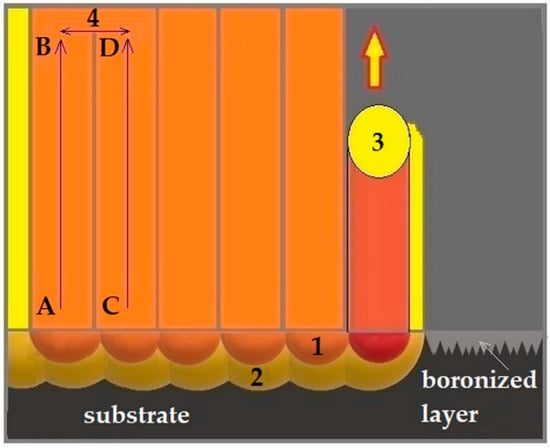
Figure 1.
Scheme of the laser processing of a diffusion boronized layer: 1—melted zone (MZ), 2—heat-affected zone (HAZ), 3—laser beam, 4—tracks overlapping.
Table 2 shows the values of the laser beam power density, exposure time of the laser beam on the material, and laser beam fluence.
Table 2.
Parameters of the laser heat treatment process.
For determining the power density, the ratio of the laser beam power and the laser beam spot area were taken into account. The exposure time of the laser beam on the material was determined on the basis of the ratio of the laser beam diameter to the laser beam scanning speed, whereas the laser beam fluence was calculated based on the ratio of the laser beam power and its exposure time on the material per laser beam spot area.
Microstructure observations were carried out using the MIRA3 scanning electron microscope (TESCAN, Brno, Czech Republic) on cross-sections perpendicular to the produced surface layer. Before observation, all specimens were polished and etched in 2% HNO3 solution. Scanning electron microscope was equipped with an EDS-UltimMax energy dispersive spectrometer (Oxford Instruments, High Wycombe, UK) and Aztec Energy Live Standard software. The phase analysis was performed on an EMPYREAN PANalytical X-ray diffractometer (PANalytical, Malvern, UK) in the angle range of 30°–60° by using Cu Kα radiation. Microhardness tests were carried out on cross-sections of the surface layer both along and on the border of laser tracks. Such measurements will allow determining whether the obtained microhardness values are comparable on the entire layer. The ZWICK 3212 B Vickers hardness tester (Zwick, Ulm, Germany) was used. The indentation load was 100 g, while the loading time was 15 s. Corrosion resistance tests were carried out using an ATLAS 1131 EU&IA device (Atlas-Sollich, Rębiechowo, Poland) in 5% NaCl aqueous solution. The potentiodynamic method of anodic polarization curves was applied. The corrosion potential and corrosion current of analyzed specimens were determined. The potentiodynamic measurements were performed at room temperature with a scanning speed of 0.5 m·V·s−1. The reference electrode was a saturated calomel electrode, and the auxiliary electrode was a platinum electrode. Wear resistance was tested on the plate-shape specimens using an Amsler-type device. The ring-shape counter-specimens were made of tool steel after hardening from 780 °C in water and tempering at 180 °C for 1 h. The hardness of the counter-specimens was 62 HRC. Wear resistance tests were performed in dry friction conditions using the following parameters: rotation speed of counter-specimen 250 rev/min, load 98 N, and friction time 180 min. The mass loss of specimens was measured using the AS220.R2 analytical balance (RADWAG, Radom, Poland) after every 30 min of wear. The resolution of weight was 0.0001 g.
3. Results and Discussion
3.1. Microstructure, Phase, and Chemical Composition
The microstructure image of the diffusion boronized layer is shown in Figure 2, while the microstructure images of layers obtained by laser processing diffusion boronized layers using various laser beam power densities is shown in Figure 3. The average thicknesses (from 10 measurements) of produced surface layers along with the standard deviation are presented in Table 3. The needle-like microstructure consisting of FeB and Fe2B iron borides characterized by good bonding with the steel substrate can be observed (Figure 2). The total thickness of boronized layers was approximately 105 µm. The area of chemical composition analysis (EDS) in the diffusion boronized layer is marked with squares in Figure 2a, while the obtained results were presented in Table 4. The boron distribution in the cross-section of the boronized layer was presented in the form of mapping in Figure 2b. The presence of boron is clearly visible only in the needle-like diffusion zone. The boron content in the analyzed area corresponds to the Fe2B phase (Table 4). However, imperfections of the EDS method should be taken into account. The EDS method is not sufficient for determining the amount of boron content because it has a relatively weak peak-to-background ratio. In addition, boron peaks often coincide with carbon peaks. Despite this, it is possible to refer to the papers in which the authors used the EDS method to indicate the boron quantity or its approximate content [39,40,41]. In this study, the EDS method was limited to three chemical elements that have a significant share in the coating, i.e., iron, boron, and carbon.
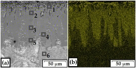
Figure 2.
Microstructure (a) and EDS mapping (b) of diffusion boronized layer.
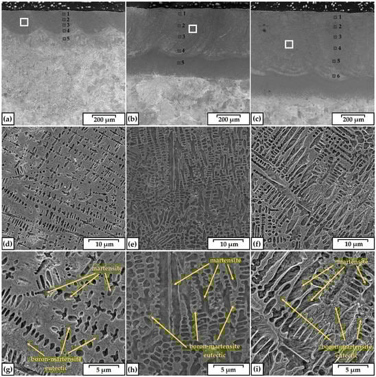
Figure 3.
Microstructure of FeB-Fe2B-Fe3(B,C) produced using laser beam power density: 76 kW/cm2 (a,d,g); 115 kW/cm2 (b,e,h); 153 kW/cm2 (c,f,i).
Table 3.
Average thickness along with the standard deviation of the diffusion boronized layer and the laser-modified boronized layers.
Figure 3a–c shows the FeB-Fe2B-Fe3(B,C) layers obtained by the laser processing of diffusion boronized layers. As a result of this process, the needle-like borides were remelted, while a newly formed layer consisted of three characteristic areas: a melted zone (MZ), heat-affected zone (HAZ) and steel substrate, which was not microstructurally changed. Figure 3a shows the laser track obtained using a laser beam power density equal to 76 kW/cm2. Figure 3d,g show the magnification of the melted zone, which was marked with a square in Figure 3a. Images were taken at 5.00 and 10.00 kx magnifications, respectively. As a result of the laser beam interaction with the diffusion boronized layer, in the melted zone, the microstructure composed of the boron–martensite eutectic with martensite was obtained. The observed microstructure was characterized by hypereutectic dendritic shapes (Figure 3g). The depth of the melted zone in the FeB-Fe2B-Fe3(B,C) layer produced by laser processing using a power density 76 kW/cm2 was approximately 197 μm. The total thickness of the obtained layer was equal to 301 μm. The heat-affected zone consisted of martensite, while the microstructurally unchanged substrate consisted of pearlite with cementite.
Figure 3b,e,h presents the images of the FeB-Fe2B-Fe3(B,C) layer produced using a laser beam power density of 115 kW/cm2. Images are presented according to the same scheme as in the previous example. The microstructure of the melted zone was composed of the boron–martensite eutectic (Figure 3h). The thickness of the melted zone in the FeB-Fe2B-Fe3(B,C) layer produced using a laser beam power density of 115 kW/cm2 was approximately 421 μm, while the total thickness (with the heat-affected zone) was equal to 559 μm. The microstructure of the layer produced using a laser beam power density of 153 kW/cm2 (Figure 3c) is shown in the same form that described previous layers. Details of the microstructure of the melted zone are presented in Figure 3f,i. In this case, the microstructure of the melted zone was composed of the boron–martensite eutectic, which had a characteristic dendritic shape with branches (Figure 3i). The thickness of the melted zone in the FeB-Fe2B-Fe3(B,C) layers produced using a laser beam power density of 153 kW/cm2 was approximately 555 μm, and its total thickness was equal to 780 μm.
It was found that the microstructure of the FeB-Fe2B-Fe3(B,C) layers changed with increasing laser beam power density. By using the lowest laser beam power density (76 kW/cm2), the boronized surfaces of specimens were heated to relatively high temperature and finally were cooled. Heat was rather quickly absorbed by the remaining specimen volume, which promoted the growth of boron eutectic in the produced layer. Therefore, a hypereutectic microstructure was detected. Increasing the laser beam power density caused an increase in the quantity of boron eutectic in the melted zone of the produced surface layer. The formation of such a microstructure resulted from the input of more heat to the specimen. This heat was not so intensely dissipated by the steel substrate as in the previous case. Therefore, at the highest laser beam power density (153 kW/cm2), the hypoeutectic microstructure was identified.
The quantitative results of chemical composition for boronized layers after laser processing are presented in Table 4. The analyzed areas were marked using squares on a cross-section of laser tracks in Figure 3a–c. As for the results of remelting the diffusion boronized layer by laser beam, the boron content is changed. With increasing distance from the surface, the boron content decreases. The laser beam power density also caused changes in the boron content due to the greater proportion of iron in the coating. The increased amount of iron came from the steel substrate. For example, in layers produced using a power density of 76 kW/cm2, approximately 6 wt.% boron was observed. Its content is lower in the bottom of the laser track, whereas increasing the laser beam power density to 153 kW/cm2 led to a decrease of boron content to around 2 wt.% in the melted zone. It can be concluded that the content of boron is dependent on the laser processing parameters.
Figure 4 presents the X-ray diffraction pattern of the diffusion boronized layer as well as the FeB-Fe2B-Fe3(B,C) layer obtained by laser processing. In the diffusion boronized layer, phases of FeB and Fe2B iron borides were detected. After laser processing of the boronized layer, in the melted zone of newly formed layers, the equilibrium phases (Fe2B and FeB) as well as non-equilibrium phase (Fe3B) were detected. The peak intensities of individual phases were dependent on the laser beam power density. It was found that the increase in power density resulted in decreased Fe3B phase intensity. A decrease in peak intensity of iron boride phases (both FeB and Fe2B) with an increasing depth of laser tracks was observed. It can be observed that the peak intensity of the iron phase slightly increases with the higher value of laser beam power density.
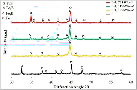
Figure 4.
X-diffraction pattern of diffusion boronized layer produced on CT90 tool steel before and after laser processing.
In paper [21], similar results were obtained. The authors focused on the production of the boronized layer by laser processing, but the source of boron was not the initial diffusion boronized layer but rather the amorphous boron precoat in the form of paste. As a result of laser processing, α-Fe, FeB, Fe2B, and Fe3B phases in the melted zone were detected. The author stated that the addition of a high amount of boron (or slight remelting of the precoat) causes the melted zone to have a hypereutectic microstructure, while a low amount of boron (or deep remelting of the precoat) contributes to the formation of the hypoeutectic microstructure. Therefore, the hypereutectic microstructure includes the phases with the highest percentage of boron, while the hypoeutectic microstructure contains phases of a lower percentage of boron, and as a consequence contributes to a reduction of peak intensity. Here, eutectic is a mixture iron borides and martensite. The increase in the laser beam power density contributes to a decrease of the share of the boron–martensite eutectic at the expense of martensite, which is visible in Figure 3i (hypoeutectic microstructure). From literature analysis, among others from the paper [42], the boron is capable of replacing carbon atoms in the compounds of Fe–C, forming the so-called “borocarbides of iron” or “borocementite” compounds, with the following chemical formulas: Fe23(C1−x,Bx)6 and Fe3(C1−x,Bx). In addition, in paper [43], the phase composition and phase transformation occurring in the iron alloys with boron content of 0.005–7.0 wt.% and carbon content of 0.4–5.5 wt.% was studied. It was found that the formation of primary phases γ-Fe, Fe2B, and Fe3(C,B) takes place depending on the boron and carbon content in alloys. Based on the EDS and XRD study results, the authors concluded that the borides forming the eutectic may contain a varying proportion of boron and carbon; therefore, the Fe3(B,C) phase is also likely.
3.2. Microhardness Profiles
The microhardness of a diffusion boronized layer produced on CT90 steel ranged from 1750 to 1580 HV and was much higher than the substrate, where it rapidly decreased to 200 HV (Figure 5). The microhardness profiles of the FeB-Fe2B-Fe3(B,C) layer produced using laser processing are shown in Figure 5. Additionally, the thicknesses in the range of the occurrence of the melted zone and heat-affected zone are marked on the graph. The microhardness was studied both along the laser track axes and along the tracks’ overlapping zone. For each laser processed layer, five measurement profiles were made. The microhardness values obtained in axes and in the overlapping zone were similar, and consequently, error bars are marked on the microhardness profiles instead of preparing double graphs. The laser processing of a diffusion boronized layer using a power density of 76 kW/cm2 allowed obtaining the microhardness of the melted zone ranging from 1200 HV0.1 to 1100 HV (Figure 5). In the heat-affected zone, this value decreased to 700 HV, and in the substrate, it decreased to approximately 200 HV. For a layer produced at 76 kW/cm2, the rate of heat dissipation was relatively low. Therefore, the microhardness in this case is the highest among the laser processed boronized layers. Rapid heating and subsequent cooling contributed to obtaining a fine microstructure (Figure 3g).
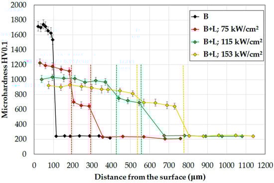
Figure 5.
Microhardness profiles of the diffusion boronized layer.
During the laser processing of a boronized layer using high laser beam power density, the heat removal was less intense, which contributes to the slower solidification of the melted zone. However, on the other hand, an increased laser beam power density led to obtaining good mixing between the borided layer and the steel substrate. This reduced the microhardness in the melted zone. An application of laser beam power density of 76 kW/cm2 led to obtaining comparable microhardness in the melted zone, which is about 1000 HV (Figure 5). The lowest (900 HV0.1) but at the same time relatively even microhardness of the melted zone was obtained using a power density of 153 kW/cm2. All obtained microhardness profiles were characterized by a mild transition through the melted zone and heat-affected zone (approximately 700 HV0.1) toward the substrate (approximately 200 HV0.1). Such types of microhardness profiles are desirable and beneficial because they promote good stress distribution in the produced layer, which is very important for industrial applications. The greater power of the laser beam, the more remelting of the material of the coating and substrate. More heat extends the solidification time of the individual coating components, which reduces thermal stresses and contributes to uniformly mixing the boron from the diffusion layer and the iron from the substrate. The remelting of the diffusion boronized layer with iron base material ensures good cohesion. However, the increased iron amount in the newly formed layer caused decreases in microhardness.
3.3. Corrosion Resistance
The results of corrosion resistance tests of the diffusion boronized layer and FeB-Fe2B-Fe3(B,C) layers produced using laser processing are presented in Figure 6 and in Table 5. Figure 6 presents potentiodynamic curves ranging from −1.2 to −0.8 V. The corrosion current (Icorr) and corrosion potential (Ecorr) values were determined by extrapolating the Tafel curves method using AtlasCorr software. Based on these corrosion tests, it can be concluded that in NaCl solution, the diffusion boronized layer had a higher corrosion resistance than the boronized layer after laser processing. Unfortunately, laser processing causes the formation of additional phases (Fe3B), which is confirmed in the results of XRD tests. Increasing the number of phases in the microstructure results in reduced corrosion resistance. In the case of the diffusion boronized layer, there is one phase on the surface (FeB), so it can be assumed that in this case, corrosion tests were carried out on a single-phase surface. However, it can be concluded that for laser-processed layers, a lower laser beam power density is more desirable. It is associated with a greater participation of boride eutectic due to the thinner melted zone, which results in higher corrosion resistance.
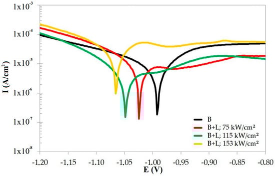
Figure 6.
Potentiodynamic curves obtained during corrosion resistance tests of the layer.
Table 5.
Corrosion resistance parameters for diffusion boronizing layers (B) and a boronized layer after laser processing (B + L).
Surface conditions after corrosion resistance tests as well as the EDS mapping of analyzed layers are shown in Figure 7. Chemical composition mapping was limited to chemical elements that have a significant share in the layer: iron (material from the surface), boron (the modifier of surface), oxygen (responsible for the formation of oxides on surface), and chlorine (component of the corrosive solution used during the tests). The surface of CT90 steel after diffusion boronizing was characterized by a greater number of large-size corrosion pits. However, the potentiodynamic study did not confirm that this layer was more susceptible to corrosion. Oxide products accumulated in the pits formed, and the rest of the boronized surface was characterized by corrosion resistance. In the case of the boronized layers produced using laser processing, the oxide products appeared on the entire area, and the distribution of oxygen was relatively even.
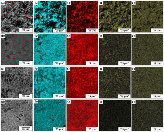
Figure 7.
EDS surface mapping of diffusion boronized layer (a), and FeB-Fe2B-Fe3(B,C) layers produced by laser processing using 76 kW/cm2 (b), 115 kW/cm2 (c), 153 kW/cm2 (d).
3.4. Wear Resistance
Figure 8 presents a comparison of the results of wear resistance for diffusion boronized layers and the FeB-Fe2B-Fe3(B,C) layers after laser processing using three different values of laser beam power density. It was found that in the case of using low and medium laser beam power density, the laser processing contributed to an increase in the wear resistance.
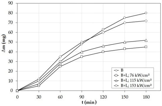
Figure 8.
Wear resistance of a diffusion boronized layer and FeB-Fe2B-Fe3(B,C) layers produced by laser processing using 76 kW/cm2, 115 kW/cm2, and 153 kW/cm2.
The obtained microstructure was composed of three zones, and the mild microhardness gradient had an influence on the good wear resistance. The higher values of wear resistance obtained for the FeB-Fe2B-Fe3(B,C) layer produced using a power density of 76 kW/cm2 were associated both with higher boron content in the melted zone as well as with obtained microhardness. In the case of the highest value of laser beam power density (153 kW/cm2), the wear resistance was much worse and close to the value recorded for the diffusion layer.
Figure 9 presents the surface conditions of all types of layers after wear resistance tests. It was found that the diffusion boronized layers were significantly damaged during the wear test. It was also found that an equally high microhardness was obtained for the FeB-Fe2B-Fe3(B,C) layers after laser processing, which resulted in a lower mass loss. It depended on the parameters of laser processing. The newly formed layers were characterized by a mild microhardness gradient between the layer and substrate. The presence of the heat-affected zone contributed to this.
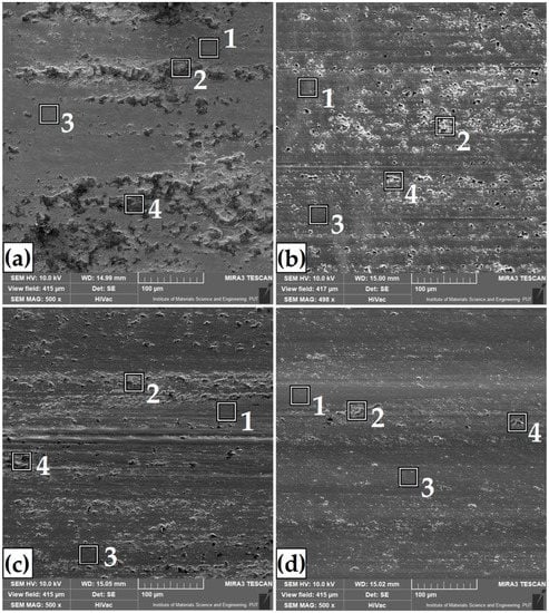
Figure 9.
Surface conditions after wear resistance tests of diffusion boronized layer (a), and FeB-Fe2B-Fe3(B,C) layers produced by laser processing using 76 kW/cm2 (b), 115 kW/cm2 (c), and 153 kW/cm2 (d).
It can be generally concluded that the increase of microhardness as well as its mild gradient from the surface to the substrate contributed to the increase of wear resistance. In all the cases of layers shown in Figure 9, characteristic traces of abrasive wear with grooving are visible. In the areas of the resulting grooves, an increased content of oxidation products is visible. The areas of chemical composition analysis after wear resistance tests were marked with squares in Figure 9, and its results are presented in Table 6.
Table 6.
EDS results of area marked in Figure 9.
4. Conclusions
As a result of a laser processing of diffusion boronized layers, a newly formed microstructure consisting of three areas (melted zone, heat-affected zone, and substrate) was obtained. The microstructure of the melted zone consisted of boron–martensite eutectic with martensite, and its amount depended on the laser processing parameters used. In the melted zone, except for a typical phase for diffusion boronized layers (FeB and Fe2B), the non-equilibrium phase Fe3B was detected. The obtained microhardness values were also dependent on laser processing parameters. The microstructure of the laser processed boronized specimen at a laser power density of 76 kW/cm2 was characterized by a higher microhardness of approximately 1200 HV0.1, while at 153 kW/cm2, it was only approximately 900 HV0.1. The laser processed boronized layer for all the presented parameters had a mild microhardness gradient between the melted zone and substrate in relation to the diffusion of boronized layers. The occurrence of a heat-affected zone is an undoubted advantage allowing a reduction in the microhardness gradient. The increase in the laser beam power density results in a decrease in the corrosion resistance. The increased iron content in the newly formed layer has an adverse influence on corrosion. Despite the lower microhardness values in the microstructure of FeB-Fe2B-Fe3(B,C) layers produced using laser processing, in comparison to diffusion boronized layers (1800 HV0.1), an increase of wear resistance was found. It was due to the occurrence of the heat-affected zone. The most favorable properties were obtained using a laser beam power density of 76 kW/cm2. The layer obtained in this way had a uniform microstructure and high microhardness (up to 1200 HV). Furthermore, this layer was characterized by the best wear resistance among all tested layers. Hence, layers obtained using these parameters can be used for many applications requiring good wear resistance, for example in metal forming processes (dies and stamps) or in the production of metal casting molds.
Funding
This research was funded with grants for education allocated by the Ministry of Science and Higher Education in Poland no. 0513/SBAD/4674.
Conflicts of Interest
The author declares no conflict of interest.
References
- Steen, W.M.; Mazumder, J. Laser Material Processing, 4th ed.; Springer: London, UK, 2010. [Google Scholar] [CrossRef]
- Hajkowski, J.; Popielarski, P.; Ignaszak, Z. Cellular automaton finite element method applied for microstructure prediction of aluminium casting treated by laser beam. Arch. Foundry Eng. 2019, 19, 111–118. Available online: http://journals.pan.pl/Content/113135/PDF/AFE+3_2019_19.pdf?handler=pdf (accessed on 23 October 2020).
- Wojciechowski, S.; Przestacki, D.; Chwalczuk, T. The evaluation of surface integrity during machining of Inconel 718 with various laser assistance strategies. MATEC Web Conf. 2017, 136, 01006. [Google Scholar] [CrossRef]
- Przestacki, D.; Kukliński, M.; Bartkowska, A. Influence of laser heat treatment on microstructure and properties of surface layer of Waspaloy aimed for laser assisted machining. Int. J. Adv. Manuf. Technol. 2017, 93, 3111–3123. [Google Scholar] [CrossRef]
- Gunes, I.; Kayali, Y. Investigation of mechanical properties of borided nickel 201 alloy. Mater Des 2014, 53, 577–580. [Google Scholar] [CrossRef]
- Ueda, N.; Mizukoshi, T.; Demizu, K.; Sone, T.; Ikenaga, A.; Kawamoto, M. Boriding of nickel by the powder pack method. Surf. Coat. Technol. 2000, 126, 25–30. [Google Scholar] [CrossRef]
- Pertek, A.; Kulka, M. Characterization of single tracks after laser surface modification of borided 41Cr4 steel. Appl. Surf. Sci. 2003, 205, 137–142. [Google Scholar] [CrossRef]
- Bartkowska, A.; Swadźba, R.; Popławski, M.; Bartkowski, D. Microstructure, microhardness, phase analysis and chemical composition of laser remelted FeB-Fe2B surface layers produced on Vanadis-6 steel. Opt. Laser Technol. 2016, 86, 115–125. [Google Scholar] [CrossRef]
- Krukovich, M.G.; Prusakov, B.A.; Sizov, I.G. Plasticity of Boronized Layers; Springer Series in Materials Science; Springer International Publishing: Berlin/Heidelberg, Switzerland, 2016; p. 237. ISBN 978-3-319-40012-9. (eBook). [Google Scholar] [CrossRef]
- Czerwinski, F. (Ed.) Thermochemical Treatment of Metals. In Heat Treatment—Conventional and Novel Applications; IntechOpen: London, UK, 2012; Chapter 5. [Google Scholar] [CrossRef]
- Taazim, N.T.; Jauhari, I.; Miyashita, Y.; Sabri, M.F.M. Development and kinetics of TiB2 layers on the surface of titanium alloy by superplastic boronizing. Metall. Mater. Trans. A 2016, 47, 2217–2222. [Google Scholar] [CrossRef]
- Bartkowski, D.; Bartkowska, A.; Popławski, M.; Przestacki, D. Microstructure, microhardness, corrosion and wear resistance of B, Si and B-Si coatings produced on C45 steel using laser processing. Metals 2020, 10, 792. [Google Scholar] [CrossRef]
- Bartkowski, D.; Bartkowska, A.; Piasecki, A.; Jurči, P. Influence of laser cladding parameters on microstructure, microhardness, chemical composition, wear and corrosion resistance of Fe–B composite coatings reinforced with B4C and Si particles. Coatings 2020, 10, 809. [Google Scholar] [CrossRef]
- Bartkowska, A.; Bartkowski, D.; Popławski, M.; Piasecki, A.; Przestacki, D.; Miklaszewski, A. Microstructure, microhardness, corrosion resistance and chemical composition of Mo, B and Mo-B coatings produced using laser processing. Materials 2020, 13, 3249. [Google Scholar] [CrossRef]
- Bartkowski, D.; Matysiak, W.; Wojtko, K. Stellite-6 surface layers reinforced with hard and refractory WC particles produced on steel for metal forming. IOP Conf. Ser. Mater. Sci. Eng. 2018, 393, 012093. [Google Scholar] [CrossRef]
- Rajput, D.; Lansford, K.; Costa, L.; Hofmeister, W. Molybdenum-on-chromium dual coating on steel. Surf. Coat. Technol. 2009, 203, 1281–1287. [Google Scholar] [CrossRef]
- Khedkar, J.; Khanna, A.S.; Gupt, K.M. Tribological behaviour of plasma and laser coated steels. Wear 1997, 205, 220–227. [Google Scholar] [CrossRef]
- Qin, L.; Yang, K.; Liu, C.; Tang, B. Enhanced plasma boriding with molybdenum using double glow plasma surface alloying technique. Mater. Lett. 2012, 82, 127–129. [Google Scholar] [CrossRef]
- Bartkowska, A.; Pertek, A. Laser production of B–Ni complex layers. Surf. Coat. Technol. 2014, 248, 23–29. [Google Scholar] [CrossRef]
- Safonov, A.N. Special features of boronizing iron and steel using a continuous wave CO2 laser. Metal Sci. Heat Treat. 1998, 40, 6–10. Available online: https://link.springer.com/article/10.1007/BF02468497 (accessed on 23 October 2020). [CrossRef]
- Morimoto, J.; Ozaki, T.; Kubohori, T.; Morimoto, S.; Abe, N.; Tsukamoto, M. Some properties of boronized layers on steels with direct diode laser. Vacuum 2009, 83, 185–189. [Google Scholar] [CrossRef]
- Kusiński, J. Lasers and Their Application in Materials Engineering; Akapit: Cracow, Poland, 2000. (In Polish) [Google Scholar]
- Dobrzański, L.A.; Jonda, E.; Labisz, K.; Bonek, M.; Klimpel, A. The comparision of tribological properties of the surface layer of the hot work tool steels obtained by laser alloying. JAMME 2010, 42, 142–147. [Google Scholar]
- Major, B. Laser modification of steel by introducing carbides and borides. 3rd Polish National Conference Surface Treatment. Conf. Mater. 1996, 263–269. [Google Scholar]
- Wiśniewski, K.; Pertek, A. Influence of laser alloying with amorphous boron on structure and microhardness of 41Cr4. Arch Metall Mater 2009, 54, 111–114. [Google Scholar]
- Sashank, S.; Babu, P.D.; Marimuthu, P. Experimental studies of laser borided low alloy steel and optimization of parameters using response surface methodology. Surf. Coat. Technol. 2019, 363, 255–264. [Google Scholar] [CrossRef]
- Nath, A.; Sarkar, S. Laser transformation hardening of steel. In Advances in Laser Materials Processing, 2nd ed.; Woodhead Publishing: Sawston, UK; Cambridge, UK, 2018; Chapter 11; pp. 257–298. [Google Scholar] [CrossRef]
- Moradi, M.; Arabi, H.; Moghadam, M.K.; Benyounis, K.Y. Enhancement of surface hardness and metallurgical properties of AISI 410 by laser hardening process; diode and Nd: YAG lasers. Optik 2019, 188, 277–286. [Google Scholar] [CrossRef]
- Karmakar, D.P.; Gopinath, M.; Nath, A.K. Effect of tempering on laser remelted AISI H13 tool steel. Surf. Coat. Technol. 2019, 361, 136–149. [Google Scholar] [CrossRef]
- Bartkowski, D.; Matysiak, W.; Bartkowska, A. Selected properties of laser cladding coatings shaped using Flowdrill technology. MATEC Web Conf. 2017, 137, 05001. [Google Scholar] [CrossRef][Green Version]
- Matysiak, W.; Bartkowski, D.; Frąckowiak, P. Microstructure, microhardness and general characterization of sintered tools using for flanging of hole edge by Flowdrill technology. IOP Conf. Series Mater. Sci. Eng. 2018, 393, 012094. [Google Scholar] [CrossRef]
- Lou, D.C.; Akselsen, O.M.; Onsøien, M.I.; Solberg, J.K.; Berget, J. Surface modification of steel and cast iron to improve corrosion resistance in molten aluminium. Surf. Coat. Technol. 2006, 200, 5282–5288. [Google Scholar] [CrossRef]
- Davis, J.R. Surface Engineering for Corrosion and Wear Resistance, 1st ed.; ASM International: Geauga County, OH, USA, 2001. [Google Scholar]
- Erdogan, A. Investigation of high temperature dry sliding behavior of borided H13 hot work tool steel with nanoboron powder. Surf. Coat. Technol. 2019, 357, 886–895. [Google Scholar] [CrossRef]
- Murakami, T.; Hibi, Y.; Mano, H.; Matsuzaki, K.; Inui, H. Friction and wear properties of the siliconized, chromized and borochromized steel substrates. Mat. Sci. Forum 2014, 783–786, 1464–1469. [Google Scholar] [CrossRef]
- Balandin, Y.A. Termochemical treatment in fluidized bed. Surface hardening of die steel by diffusion boronizing, borocopperizing and borochromizing in fluidized bed. Met. Sci. Heat Treat 2005, 47, 103–106. Available online: https://link.springer.com/article/10.1007/s11041-005-0037-z (accessed on 23 October 2020). [CrossRef]
- Sikorski, K.; Wierzchoń, T.; Bieliński, P. X-ray microanalysis and properties multicomponent plasma-borided layers on steels. J. Mater. Sci. 1998, 33, 811–815. Available online: https://link.springer.com/article/10.1023/A:1004322719560 (accessed on 23 October 2020). [CrossRef]
- Prince, M.; Arjun, S.; Raj, G.S.; Gopalakrishnan, P. Experimental investigations on the effects of multicomponent laser boriding on steels. Mater. Today Proc. 2018, 5, 25276–25284. [Google Scholar] [CrossRef]
- Dénes, É.; Tóth, A.L.; Enikő-Réka, F. Qualitative and quantitative analysis of boron content precipitates by FEG-SEM and EDS method. In Materials Science Forum; Trans Tech Publications Ltd.: Kapellweg, Switzerland, 2010; Volume 659, pp. 295–300. [Google Scholar] [CrossRef]
- Tavsanoglu, T.; Jeandin, M.; Addemir, O.; Agirseven, O.; Yucel, O. An imaging SIMS study on the tribological properties of boron carbide thin films. Surf. Interface Anal. 2013, 45, 587–591. [Google Scholar] [CrossRef]
- Piasecki, A.; Kulka, M.; Kotkowiak, M. Wear resistance improvement of 100CrMnSi6-4 bearing steel by laser boriding using CaF2 self-lubricating addition. Tribol. Int. 2016, l97, 173–191. [Google Scholar] [CrossRef]
- Vdovin, K.N.; Zaitseva, A.A.; Feoktistov, N.A. Research of properties and structure of boron-modified roll-foundry iron. J. Mater. Sci. Res. 2016, 5, 88–99. [Google Scholar] [CrossRef]
- Filonenko, N.Y.; Galdina, A.N.; Babachenko, A.I.; Kononenko, G.A. Structural state and thermodynamic stability of Fe–B–C alloys. Phys. Chem. Solid State 2019, 20, 437–444. [Google Scholar] [CrossRef]


Publisher’s Note: MDPI stays neutral with regard to jurisdictional claims in published maps and institutional affiliations. |
© 2020 by the author. Licensee MDPI, Basel, Switzerland. This article is an open access article distributed under the terms and conditions of the Creative Commons Attribution (CC BY) license (http://creativecommons.org/licenses/by/4.0/).