Article

Anticorrosion Properties of the Low-Temperature Glow Plasma Nitriding Layer on AISI 904L Austenitic Stainless Steel in Hydrofluoric Acid Obtained at Various NH3 Pressures

1
College of Materials and Metallurgy, Guizhou University, Guiyang 550025, China
2
Key Laboratory for Mechanical Behavior and Microstructure of Materials of Guizhou Province, Guiyang 550025, China
3
National & Local Joint Engineering Laboratory for High-Performance Metal Structure Material and Advanced Manufacturing Technology, Guiyang 550025, China
*
Authors to whom correspondence should be addressed.
Coatings 2020, 10(12), 1156; https://doi.org/10.3390/coatings10121156
Submission received: 5 November 2020 / Revised: 24 November 2020 / Accepted: 25 November 2020 / Published: 26 November 2020
(This article belongs to the Section Thin Films)

Abstract

:
A low-temperature (400 °C) glow plasma nitriding layer on AISI 904L austenitic stainless steel was obtained at various NH3 pressures and studied using electrochemical method, X-ray diffraction, and scanning Kelvin probe. The pressure of NH3 dominated the microstructure of the nitriding layer. The saturation degree of γN controlled corrosion performance and microhardness. Insufficient NH3 pressure (<100 Pa) resulted in discontinuous nitride caking coverage, whereas excessive NH3 pressure (>100 Pa) facilitated the transformation of the nitriding layer to harmful nitrides (CrN) due to a localized overheating effect caused by the over-sputtering current.

1. Introduction

Austenitic stainless steels (ASSs) are employed in many industrial fields due to their corrosion resistance, ease of formability, and weld ability [1,2,3]. The corrosion resistance of ASSs in chloride solution or H2SO4/HF has been reported [4,5], whereas the corrosion of stainless steel in HF has received little attention. Although polymer materials, such as polytetrafluoroethylene (PTFE), are more widely used in HF-related industries than stainless steel to prevent corrosion, metals are irreplaceable in some cases. The present research originated from an engineering problem in a heat exchanger in the phosphorite exploitation industry. The metal tubes of heat exchangers suffer from HF-containing solvent and mineral particle wear. Therefore, stainless steel with high surface hardness can be ideal tube materials.
Nitriding is effective in improving hardness and tribological properties, but conventional gas nitriding weakens the anticorrosion properties of ASS by forming a dense CrN film. Owing to their high diffusion coefficient, the Cr atoms in stainless steel preferentially bind with N atoms during nitriding. Thus, the Cr-depleted austenitic matrix zones cannot form a uniform and protective passive film subject to active corrosion [6,7]. In order to avoid elemental diffusion of the substrates, some novel coating technologies were proposed. D’Avico et al. [8] studied the wetting properties of four physical vapor deposition (PVD) nitride coatings (AlTiN, NbN, ZrN, and TiN) on a martensitic stainless steel. Gaona-Tiburcio et al. [9] studied the corrosion resistance of multilayer coatings deposited by PVD on Inconel 718 and found that the AlCrN/AlCrN + CrN coating showed better performance in the sulfuric acid solutions. Mihaela et al. [10] deposited a chromium nitride and oxynitride coatings on 304 steel substrates as monolayers by reactive cathodic arc method. Therefore, nitride coatings are a very promising anticorrosive technology.
Recently, low-temperature glow plasma nitriding (LTN) has received increasing attention in the last years [11]. It is an effective surface engineering technique that can avoid the problems of CrN precipitation [6,12]. Fossati et al. [13] found that nitriding treatments performed at low temperatures (<450 °C) allow the production of modified layers composed of an N-supersaturated austenitic metastable phase, known as the S phase [14], or an expanded austenite [15], which has high hardness and improved corrosion resistance.
AISI 904L is a superaustenitic stainless steel with high Ni-to-Mo ratio [16]. Bellezze et al. [17,18] compared the corrosion rates of six kinds of stainless steels in a mixture of H2SO4/HCl and suggested that the 904L ASS shows the lowest corrosion rates and can be the most reliable alternative to AISI 316L because of the former’s high Ni, Cr, Mo, and Cu contents. However, the corrosion behaviors of AISI 904L ASS in HF acid are seldom studied. In our previous study [3], the behavior of un-nitrided 904L ASS in HF is distinct from that in HCl. The precipitation of a protective but loose insoluble layer on the surface of 904L in HF is proven to be a preferential reaction between (F) and (Ni) from the alloy. Therefore, improving the surface hardness of 904L ASS without reducing corrosion resistance through LTN is of great importance for the service life of ASSs under erosion–corrosion conditions.
The present research aims to investigate the corrosion resistance of 904L ASS nitrided at different pressures in HF solution through LTN. The microstructure, phase composition, hardness, and corrosion resistance of the nitrided specimens are investigated and compared with those of the untreated specimens.

2. Materials and Methods

2.1. Materials

The steel used herein was hot-rolled AISI 904L ASS with the following chemical composition (wt.%); C = 0.016, Cr = 19.68, Ni = 24.08, Mo = 4.293, Mn = 1.470, Si = 0.292, S < 0.15, P = 0.027, N = 0.084, Cu = 1.273, and balanced Fe. AISI 904L was cut into Φ25 mm × 4 mm specimens. The surfaces of the nitrided specimens were first sequentially ground with 800, 1000, 1500, and 2000 grit emery paper and then polished to a mirror surface with 2.5 μm alumina pastes. Prior to nitriding, the specimens were cleaned ultrasonically in ethanol for 15 min and dried in cold air.

2.2. Nitriding

LTN was performed on plasma equipment (LMDC-30AZ, Ande, Wuhan, China). Before glow discharge treatment, the pressure in the furnace was controlled at 15 Pa. The nitriding pressure was maintained using a dynamic flow-controlled vacuum system. Prior to the nitridation step, sputtering was performed to remove the natural passivation film and enable uniform nitridation. At 25 Pa, the arc discharge began to heat up, and the ammonia flow rate was 0.14 L/min. When the pressure was stable and gradually increasing, the gas flow rate was gradually increased to 0.34–0.37 L/min. The gas pressure was stabilized at 75–150 Pa, and the temperature was maintained at 400 °C to begin nitriding. The processing temperature, voltage, current, NH3 flow rate, and time were 400 °C, 750 V, 3.5–4.0 A, 0.28–0.34 L/min, and 6 h, respectively. The nitriding pressures used were 75, 100, 125, and 150 Pa.

2.3. Morphological Characterization

The metallographic morphology was characterized through an optical microscope (GX51, Olympus, Tokyo, Japan). The illuminant of the OM was 6v30whal halogen lamps and reflective light mode was operated. The microstructure and was characterized through the scanning electron microscopy (SEM, ZEISS SUPRE40, Jena, Germany). The accelerating voltage was 10 kV, and the mode for SEM observation was InLens (an imaging method for receiving SE1 signals proposed by ZEISS Company).
The cross section morphology of the nitriding layer was finally polished with argon ions (EM TIC 3X, Leica, Jena, Germany). After the specimen was put into the sample preparation platform, the instrument was vacuumed to below 2 × 10⁻⁴ Pa, and the air pressure of argon gas was adjusted to be 500–700 Pa. The argon ion polisher was thinned by three ion guns in turn. The energy parameters and thinning time of the ion gun were set as 5500 V 15 min, 4500 V 10 min, 3500 V 10 min, and 3000 V 20 min, respectively. Then, the rotating speed of the sample preparation platform was adjusted to medium, and the tilt angle was selected as 4.5°.

2.4. Microhardness

The microhardness of the nitriding layer was examined using the Vickers microhardness tester (HVS-1000, Huayin, China) by using a load of 100 g. Three parallel specimens were tested for each set of data. The average hardness value of each specimen was gained from 10 points on the surface.

2.5. X-ray Diffraction

The phase composition of the surface layers was identified by X-ray diffraction analysis (X’Pert Powder, PANalytical B.V., Almelo, The Netherlands). The diffraction spectrum was collected in the Bragg–Brentano configuration (Cu Kα radiation) at a working voltage, working current, and scanning angle of 40 kV, 40 mA, and 20°–100°, respectively. The spectrum was analyzed by MDI Jade 9 Software and the database was the ICDD PDF4-2009 [19].

2.6. Electrochemical Tests

Electrochemical polarization experiments were performed in 1 mol/L HF solution to evaluate the corrosion resistance of the specimens by using an electrochemical workstation (CorrTest CS350, Wuhan, China). As shown in Figure 1, an electrolytic cell mainly composed of PTFE was designed for electrochemical testing. The nitrided specimen can be easily installed on the device without any epoxy resin and mechanically sealed using a fluororubber seal ring, leaving an area of 1 cm2 exposed to the electrolyte. A saturated calomel reference electrode (SCE) was connected to the cell through the Luggin capillary made by PTFE. A Pt sheet was used as the counter electrode.
To achieve a steady-state condition, the specimens were immersed in the solution for 30 min before the open circuit potential tended toward stability. Parallel experiments were conducted five times to ensure accuracy. The scanning rate of the polarization curve was 0.1 mV/s at a scanning range of −1.5 to +1.5 V vs. open circuit potential (OCP).

2.7. Immersed Corrosion Test

A small electrolytic tank composed of PTFE was designed for the immersion test. Nitrided specimens were individually placed in the PTFE tank. Only one side of the specimen was exposed to the HF solution. The capacity of each PTFE tank was 120 mL, and the concentration of the HF solution was 1 mol/L. All PTFE tanks containing the specimens were placed into a thermostat (30 °C) for 72 h. Each tank had a sealed cover to prevent vapor leakage. The specimens were removed after immersion, cleaned ultrasonically in distilled water for 5 min, dried in cold air, and preserved in a vacuum drying oven at ambient temperature.

2.8. Scanning Kelvin Probe (SKP)

The SKP technique was used to measure the electron work function on a metal surface in vacuum or air and record the potential maps of the nitrided and untreated specimens. The experiments were performed on the electrochemical scanning workstation (PARM370, Ametec, San Diego, CA, USA). The test was conducted in air at room temperature in surface scan stepscan mode. The vibration amplitude of the probe was 30 µm, and the average distance between the probe and the specimen surface was 100 µm. The scanning area was 1000 µm × 1000 µm, and the step length was 20 μm.

3. Results

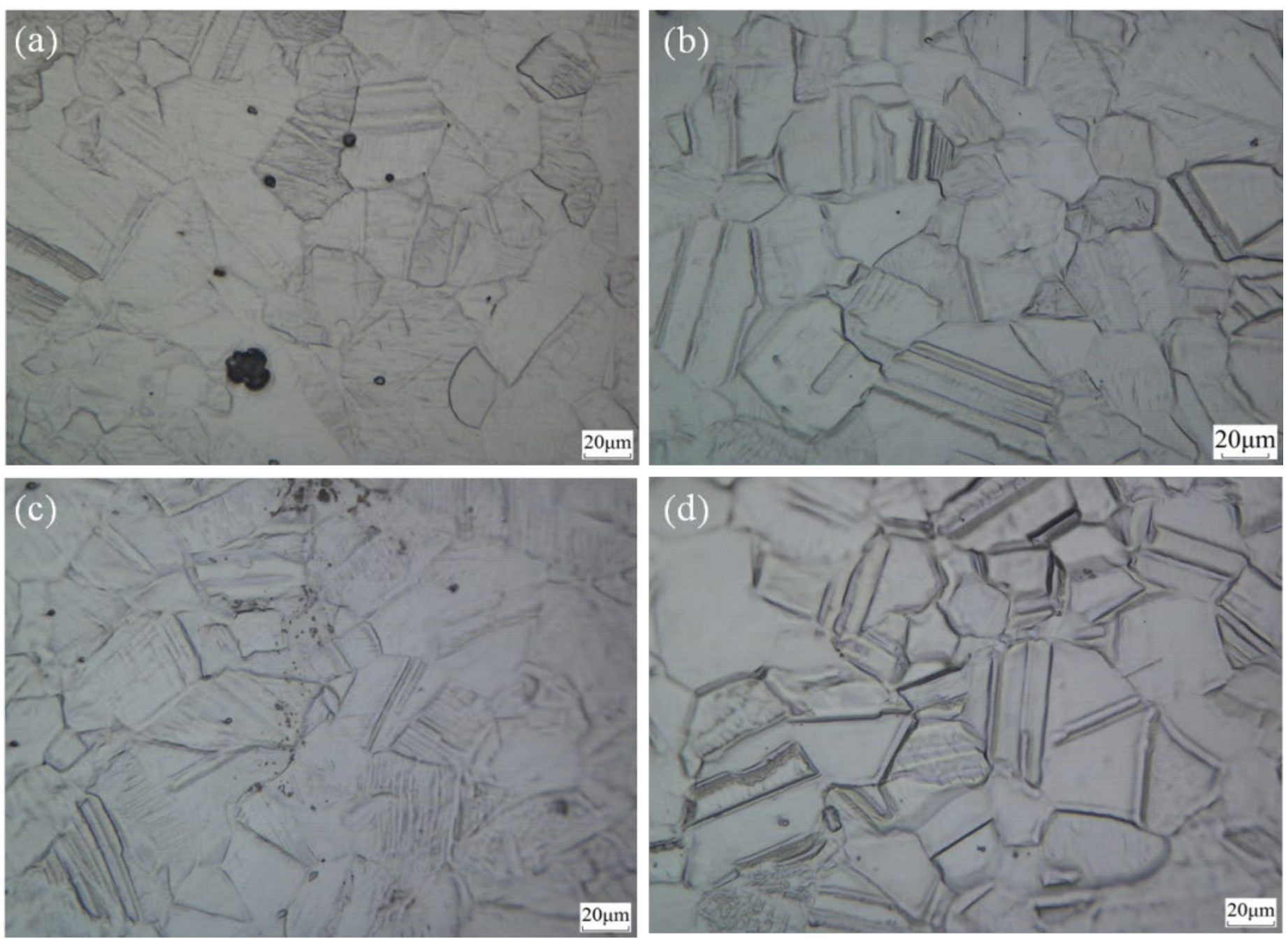
3.1. Optical Micrograph and Microhardness

The optical micrographs of the specimens subjected to LTN at 75, 100, 125, and 150 Pa without etching are shown in Figure 2. The black pitting was the cathodic sputtering damage caused by the glow discharge [20,21], and the amount of such pitting decreased with increasing NH3 pressure. Interestingly, grain boundaries, twins, and slip lines can be clearly distinguished without etching and were similar to the metallographic structures that had spontaneously grown from the base. In essence, the bulging morphology bearing the γN formation, known as expanded austenite [15], and the distortion and contraction of lattices caused the plastic deformation of the surface grains during the diffusion of active N atoms [20,21].
The Vickers microhardness of untreated and nitrided 904L ASSs are shown in Figure 3. Compared with that of the 904L ASS matrix, the microhardness of all the specimens subjected to LTN at different NH3 pressures had greatly improved. The specimens treated at 100 Pa exhibited the highest microhardness (1409.09 HV). Results were obtained several times to verify that 100 Pa was the optimal pressure. The improvement in hardness due to increasing the pressure from 75 to 100 Pa can be interpreted as the efficiency of nitriding and the formation of a highly saturated γN structure at 100 Pa due to the increased concentration of surrounding activated N atoms. However, this interpretation was not supported by the sharp reduction in microhardness at increased pressure, new compounds or phases were supposed to be generated which need further analysis below.

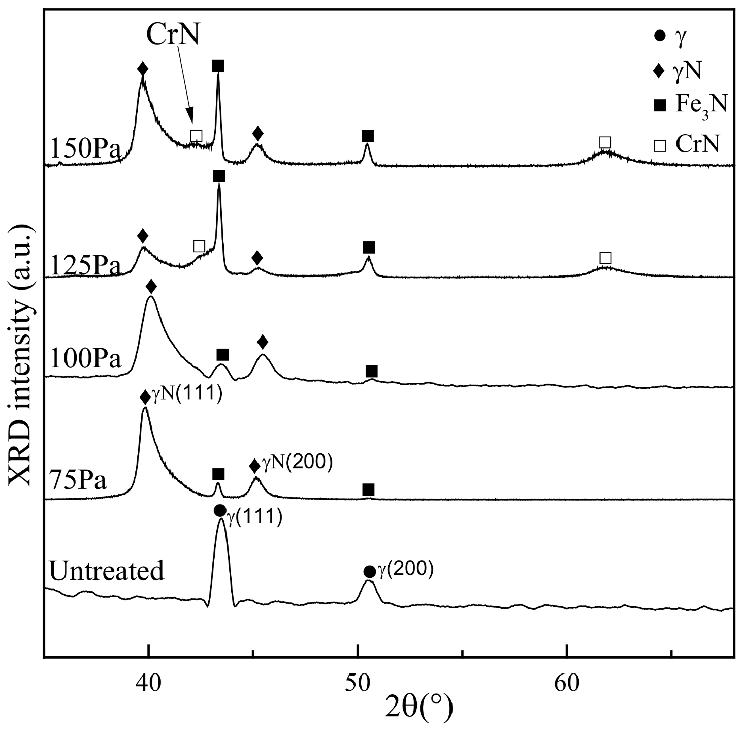
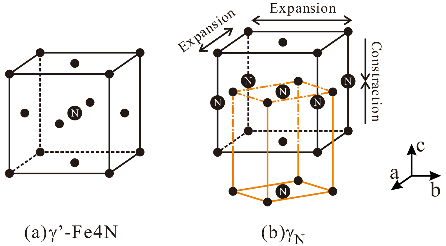
3.2. X-ray Diffractometer (XRD) Spectrum Analysis

The XRD spectrums of the specimens are shown in Figure 4. The diffraction peaks of γN(111) and γN(200) at 40.02° and 45.28°, respectively, were ascribed to the expanded austenite [15]. The N dissolved in the interstitices of the solid solution distorted the lattice structure of austenite, resulting in the shifting of the γ(111) and γ(200) diffraction peaks to a low reflection angle. As shown in Figure 5, the γ’-Fe4N phase was a face-centered cubic (fcc) structure, and the γN phase was an N-saturated austenite, which was a face-centered tetragonal (fct) lattice structure derived from fcc cells [22]. The dissolved N atoms located at the center of the cell and at the middle positions of the four c axes deformed the cell through a slight expansion in the a/b direction and corresponding concentration in the c direction relative to those in the unit cell of γ’-Fe4N [22].
At low pressure (≤100 Pa), a weak diffraction peak emerged between the peaks of γN(111) and γN(200). This peak indicated that a small fraction of Fe3N [23] was generated in the nitriding layer. The intensity of this diffraction peak drastically increased in specimens subjected to high NH3 pressure (≥125 Pa). Therefore, these results suggested that the concentrated N accelerated the synthesis of Fe3N at increased NH3 pressure. In addition, the appearance of diffraction peaks at 42.2° and 61.9° reflected the generation of CrN [23]. Therefore, the reduced microhardness of specimens treated at 100 Pa can be attributed to the formation of a brittle nitride in the nitriding layer.

3.3. Electrochemical Behavior

The anodic potentiodynamic polarization curves of 904L specimens in 1 mol/L HF solution treated at different NH3 pressures were measured. Results are shown in Figure 6. The anodic passivation behavior of treated specimens was remarkably different from that of the untreated bare metal. The untreated specimen exhibited the typical passivation curve of a stainless steel that included active dissolution and passivation ranges. By contrast, the nitrided specimens underwent two stages of passivation: The first stage (Stage 1) occurred over the potential range of OCP to −0.02 V vs. SCE. The increase in anodic current was inhibited compared with that in the active dissolution current of bare metal. The second stage (Stage 2) occurred over the potential range of 0.02 to 0.50 V vs. SCE. This range overlapped with the passivation range of the untreated specimen. Therefore, the inhibition of the activated current at Stage 1 was attributed to the blocking effect of the nitriding layer, which considerably decreased the maximum current for passivation. Moreover, given that the potential entered the passivation range of bare 904L ASS, the second decrease in anodic current at Stage 2 was due to the passivation of the base metal under the nitriding layer.
The nitriding layer exhibited different electrochemical behaviors at various treatment pressures. As mentioned above, the nitriding layer restricted the active dissolution of bare 904L ASS in the first stage. Thus, the lowest current density obtained at 100 Pa indicated that the most protective nitriding layer had formed on the specimen, i.e., low or high treatment pressures cannot restrict active dissolution as well as 100 Pa. As shown by XRD analysis, the formation of γN in the nitriding layer was not saturated at low treatment pressure (75 Pa) compared with that at 100 Pa. The remaining untransformed original austenite accelerated active dissolution at the first stage. As the treatment pressure exceeded 100 Pa, the synthesis of Fe3N broke the integrity of the nitriding layer by forming corrosion microbatteries. Moreover, as the treatment pressure reached 150 Pa, a large current peak emerged before passivation at the second stage. Meanwhile, the current density for maintaining the passivity state was considerably higher than the other densities. This phenomenon was consistent with Cr-depleted theories [6,7], which state that the generation of CrN depletes the Cr content in austenite to inhibit the formation of a protective passive film.

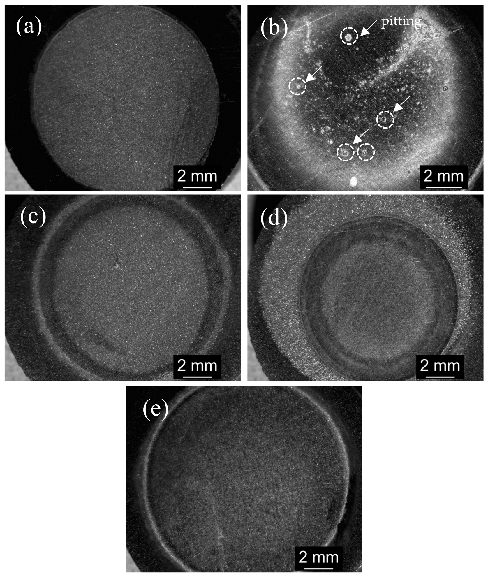
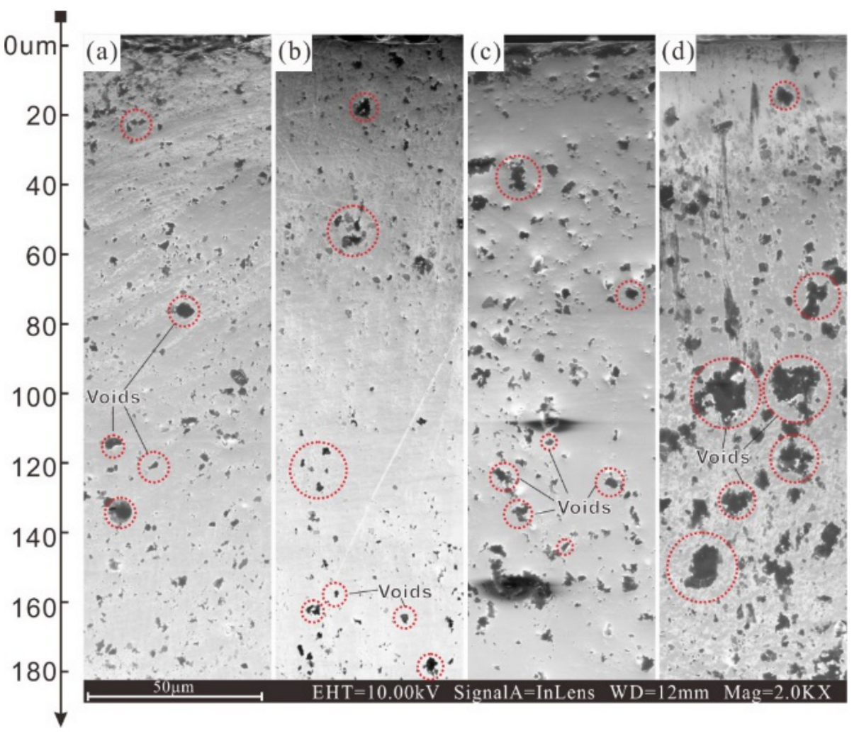
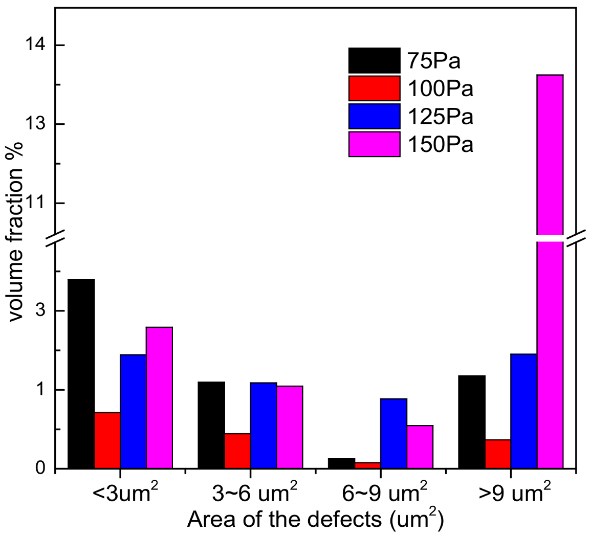
3.4. Corrosion Morphology Analysis
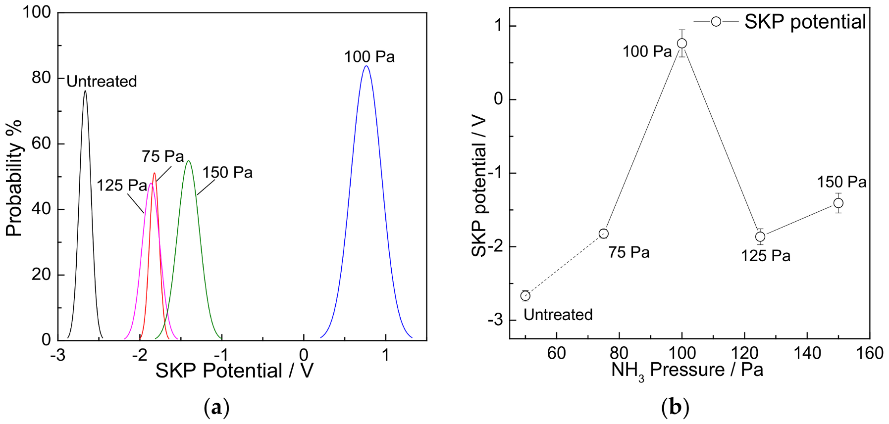
The corrosion morphology of the specimens after 72 h of immersion in 1 mol/L HF was analyzed through SEM as shown in Figure 7 and Figure 8. The macromorphology of the corroded specimens with a nitriding layer is shown in Figure 7. The ring-like feature around the specimens was caused by the seal ring, which created a nonuniform diffusion condition near the circular boundary. A certain amount of pitting occurred on the specimen treated at 75 Pa (Figure 7b). This feature suggested that a nitriding layer was formed at insufficient NH3 pressure in an unsaturated state with a high density of localized defects.
The micromorphology of the untreated and nitrided specimens is shown in Figure 8. Different forms of corroded nitriding layer covered the 904 L base metal. As observed, the untreated 904 L exposed the base metal without any protective layer covered (Figure 8a). In Figure 8b (75 Pa), a large amount of block-shaped caking spread on the surface. This feature indicated that a discontinuous nitriding layer was formed under insufficient NH3 pressure. Thus, the preferential dissolution of the partially un-nitrided austenite resulted in disconnected nitride caking. Figure 8c (100 Pa) showed that the nitriding layer was highly compact. The micropores (<0.5 μm) embedded in the nitriding layer were due to the localized dissolution of the nitriding layer on the regions with a high density of defects. As the pressure of NH3 increased, the structure of this nitriding layer appeared grainy as shown in Figure 8d (125 Pa). This phenomenon indicated that the nitriding layer was involved in the synthesis of Fe3N and the high concentration of atmospheric NH3 can promote the combination of the active N atom with the γN phase. At increased concentration of NH3, the generation of CrN induced the formation of a porous structure, as shown in Figure 8e (150 Pa). Considering the Cr depletion effect, the short-ranged diffusion of the Cr element in the slip band of austenite grain caused the appearance of grooves on the grain surface due to preferential solution. Therefore, the drastic increase in the passivity-containing current can be attributed to the high density of grooves and pores on the nitriding layer.
The cross section morphology of the specimens after 72 h of immersion in 1 mol/L HF is shown in Figure 9. In order to maximumly preserve the fragile structure of the corroded nitriding layer, the cross section of specimens were polished with argon ion. As can be seen, there was a larger amount of defect of cavities in the nitriding layer; the statistic results as shown in Figure 10. This phenomenon indicated that the nitriding layer behaved like a porous medium when immersed the HF. Therefore, the compactness of the nitriding layer dominated the corrosion resistance in HF. As shown in Figure 9b, the nitriding layer formed under 100 Pa exhibited the best compactness, especially at depth region near 70 to 120 μm, less defect of cavities blocking the diffusion path of the aggressive ion. Compared with the nitriding layer at 100 Pa, the amount and diameter of cavity was significantly increased in the nitriding layer at 125 and 150 Pa. This results indicated that the excess pressure of NH3 deteriorate the protection properties of nitriding layer by accelerate the localized corrosion in the nitriding layer as mentioned above.

3.5. SKP

The results obtained with the SKP system are shown in Figure 11 and Figure 12. The φ symbol represents the Volta potential difference measured between the SKP reference probe and the surface of the nitriding layer (φ = φspecimen − φref), and a positive Volta potential measured for a specimen represents high electron work function (EWF). The Volta potential of all nitrided specimens was more positive than that of the untreated specimen, indicating the inertness of the nitriding layer for electron escape. Therefore, as stated in the electrochemical behavior section, the inhibitory effect of the nitriding layer can be attributed to the inert oxidation property.
Notably, the Volta potential of specimens at 100 Pa was more positive than that of the others, and such variation agreed well with the microhardness results shown in Figure 3. Therefore, the microstructure of the nitriding layer controlled the electrical properties. Considering that γN was a supersaturated interstitial solid solution, N atoms at the interstitial vacancy likely impeded the flow of free electrons. In other words, the expansion of the austenitic lattice by N atom interstitial diffusion broadened the forbidden band that increased EWF. Moreover, the coverage by nitride precipitates cannot change the conductive properties of the base metal as well as the interstitial solid solution. Therefore, the negative shift in Volta potential of the specimens at increased pressures can be attributed to a change in composition. Additionally, the slight increase in potential at 150 Pa was due to the noble metal properties of Cr.

4. Discussion

The results indicated that an optimal NH3 pressure exists for the formation of a premium nitriding layer by LTN. Nevertheless, the mechanisms for the synthesis of harmful nitrides (CrN) at high NH3 pressure remain unclear. Based on the glow discharge principle, increased NH3 pressure simply increased the concentration of the activated N atoms. Thus, from a physicochemical perspective, a high N atom concentration increases the chemical potential of the reactants that promote nitride synthesis. However, a critical temperature for chemical reaction exists. The temperature of the glow discharge chamber was maintained at 400 °C, which was 50 °C lower than the LTN temperature recommended by other studies [2,3,4]. Therefore, the increased concentration of N atoms cannot be a key factor in the synthesis of harmful nitrides.
Yang [23] studied the current density that affects the nitriding layer by LTN and reported that a high current setting induced an intensive etching of the excessive sputtering surface of the nitriding layer. In the present study, the voltage for glow discharge was maintained at 750 V, and the current intensity was dependent on the discharge efficiency on specimens. Therefore, increasing the pressure of the NH3 atmosphere amplified the discharge current density. The surface temperature on the discharging specimen was inconsistent with the ambient temperature in the chamber, and the high energy of ion sputtering induced a heating effect on the treated surface. Thus, under concentrated ion sputtering, the high temperature of the specimens’ surface activated the synthesis of harmful nitrides.

5. Conclusions

In accordance with the results of this study. NH3 pressure should be maintained at 100 Pa. High microhardness and anticorrosion performance can be obtained through the formation of saturated γN structures.
An inadequate NH3 pressure (75 Pa) resulted in a discontinuous nitriding layer, and the preferential dissolution of the partially un-nitrided austenite resulted in disconnected nitride caking.
An excessively high NH3 pressure (125, 150 Pa) resulted in a porous structure after corrosion in HF. The deterioration of corrosion resistance mainly attributes to the synthesis of harmful nitrides (CrN). Besides, the localized overheating effect on the nitriding surface caused by higher intensive density of sputtering current promotes the synthesis of CrN.

Author Contributions

Conceptualization, W.S. and J.W.; methodology, W.S.; software, R.J.; validation, S.X., W.S., and J.W.; formal analysis, W.S.; investigation, W.S.; resources, W.S.; data curation, R.J.; writing—original draft preparation, J.W.; writing—review and editing, W.S.; visualization, W.S.; supervision, W.S.; project administration, S.X.; funding acquisition, W.S. All authors have read and agreed to the published version of the manuscript.

Funding

This research was funded by the National Natural Science Foundation of China (Grant Nos. 51661006, 51774103, 51801038, and 51974097), the Program of “One Hundred Talented People” of Guizhou Province (Grant No. 20164014), Guizhou Province Science and Technology Project (Grant Nos. 20175656, 20175788, 20191414, (2018)5781, and 20192162).

Conflicts of Interest

The authors declare no conflict of interest.

References

  1. Jones, R.; Randle, V.; Owen, G. Carbide precipitation and grain boundary plane selection in overaged type 316 austenitic stainless steel. Mater. Sci. Eng. A 2008, 496, 256–261. [Google Scholar] [CrossRef]
  2. Schwind, M.; Källqvist, J.; Nilsson, J.O. σ-phase precipitation in stabilized austenitic stainless steels. J. Acta Mater. 2000, 48, 2473–2481. [Google Scholar] [CrossRef]
  3. Zou, G.; Shi, W.; Xiang, S.; Ji, X.; Ma, G.; Ballinger, R.G. Corrosion behavior of 904L austenitic stainless steel in hydrofluoric acid. RSC Adv. 2018, 8, 2811–2817. [Google Scholar] [CrossRef] [Green Version]
  4. Fernandes, F.A.P.; Heck, S.; Pereira, R.; Picon, C.; Nascente, P.; Casteletti, L.C. Ion nitriding of a superaustenitic stainless steel: Wear and corrosion characterization. Surf. Coat. Technol. 2010, 204, 3087–3090. [Google Scholar] [CrossRef]
  5. Fossati, A.; Galvanetto, E.; Bacci, T.; Borgioli, F. Improvement of corrosion resistance of austenitic stainless steels by means of glow-discharge nitriding. Corros. Rev. 2011, 29, 209–221. [Google Scholar] [CrossRef]
  6. Li, X.; Thaiwatthana, S.; Dong, H.; Bell, T. Thermal stability of carbon S phase in 316 stainless steel. Surf. Eng. 2002, 18, 448–451. [Google Scholar] [CrossRef]
  7. Zhang, Z.L.; Bell, T. Structure and corrosion resistance of plasma nitrided stainless steel. Surf. Eng. 1985, 1, 131–136. [Google Scholar] [CrossRef]
  8. D’Avico, L.; Beltrami, R.; Pargoletti, E.; Trasatti, S.P.; Cappelletti, G. Insight into the release agents/PVD coatings interaction for plastic mold technology. Coatings 2020, 10, 281. [Google Scholar] [CrossRef] [Green Version]
  9. Gaona-Tiburcio, C.; Montoya-Rangel, M.; Cabral-Miramontes, J.A.; Estupiñan-López, F.; Zambrano-Robledo, P.; Orozco-Cruz, R.; Chacon-Nava, J.; Baltazar-Zamora, M.A.; Almeraya-Calderón, F. Corrosion resistance of multilayer coatings deposited by PVD on inconel 718 using electrochemical impedance spectroscopy technique. Coatings 2020, 10, 521. [Google Scholar] [CrossRef]
  10. Dinu, M.; Mouele, E.S.; Parau, A.C.; Vladescu, A.; Petrik, L.F.; Braic, M. Enhancement of the corrosion resistance of 304 stainless steel by Cr–N and Cr(N,O) coatings. Coatings 2018, 8, 132. [Google Scholar]
  11. Lo, K.; Shek, C.; Lai, J. Recent developments in stainless steels. Mater. Sci. Eng. R Rep. 2009, 65, 39–104. [Google Scholar] [CrossRef]
  12. Borgioli, F.; Galvanetto, E.; Bacci, T. Low temperature nitriding of AISI 300 and 200 series austenitic stainless steels. Vacuum 2016, 127, 51–60. [Google Scholar] [CrossRef]
  13. Collins, G.A.; Hutchings, R.; Short, K.T.; Tendys, J.; Li, X.; Samandi, M. Nitriding of austenitic stainless steel by plasma immersion ion implantation. Surf. Coat. Technol. 1995, 74, 417–424. [Google Scholar] [CrossRef]
  14. Christiansen, T.; Somers, M.A.J. On the crystallographic structure of S-phase. Scr. Mater. 2004, 50, 35–37. [Google Scholar] [CrossRef]
  15. Maistro, G. Microstructural Characterization of Expanded Austenite in 304L and 904L Austenitic Stainless Steels; Chalmers University of Technology: Gothenburg, Sweden, 2015. [Google Scholar]
  16. Ramkumar, K.D.; Chandrasekhar, A.; Srivastava, A.; Preyas, H.; Chandra, S.; Dev, S.; Arivazhagan, N. Effects of filler metals on the segregation, mechanical properties and hot corrosion behaviour of pulsed current gas tungsten arc welded super-austenitic stainless steel. J. Manuf. Process. 2016, 24, 46–61. [Google Scholar] [CrossRef]
  17. Bellezze, T.; Giuliani, G.; Viceré, A.; Roventi, G. Study of stainless steels corrosion in a strong acid mixture. Part 2: Anodic selective dissolution, weight loss and electrochemical impedance spectroscopy tests. Corros. Sci. 2018, 130, 12–21. [Google Scholar] [CrossRef]
  18. Bellezze, T.; Giuliani, G.; Roventi, G. Study of stainless steels corrosion in a strong acid mixture. Part 1: Cyclic potentiodynamic polarization curves examined by means of an analytical method. Corros. Sci. 2018, 130, 113–125. [Google Scholar] [CrossRef]
  19. Haruman, E.; Sun, Y.; Adenan, M.S. A comparative study of the tribocorrosion behaviour of low temperature nitrided austenitic and duplex stainless steels in NaCl solution. Tribol. Int. 2020, 151, 106412. [Google Scholar] [CrossRef]
  20. Dearnley, P.A.; Aldrich-Smith, G. Corrosion—wear mechanisms of hard coated austenitic 316L stainless steels. Wear 2004, 256, 491–499. [Google Scholar] [CrossRef]
  21. Nakanishi, T.; Tsuchiyama, T.; Mitsuyasu, H.; Iwamoto, Y.; Takaki, S. Effect of partial solution nitriding on mechanical properties and corrosion resistance in a type 316L austenitic stainless steel plate. Mater. Sci. Eng. A 2007, 460, 186–194. [Google Scholar] [CrossRef]
  22. Yasumaru, N. Low-temperature ion nitriding of austenitic stainless steels. Mater. Trans. JIM 1998, 39, 1046–1052. [Google Scholar] [CrossRef] [Green Version]
  23. Yang, W.; Zhang, M.; Zhao, Y.; Shen, M.; Lei, H.; Xu, L.; Xiao, J.; Gong, J.; Yu, B.; Sun, C. Enhancement of mechanical property and corrosion resistance of 316L stainless steels by low temperature arc plasma nitriding. Surf. Coat. Technol. 2016, 298, 64–72. [Google Scholar] [CrossRef]
Figure 1. Schematic diagram of the designed electrolytic cell made with polytetrafluoroethylene.
Coatings 10 01156 g001
Figure 2. Optical micrographs of nitrided 904L austenitic steel (ad). Glow plasma nitriding was conducted at 400 °C and (a) 75, (b) 100, (c) 125, and (d) 150 Pa.
Coatings 10 01156 g002
Figure 3. Microhardness of the untreated and the nitrided 904L specimens at 400 °C and 75, 100, 125, and 150 Pa for 6 h.
Coatings 10 01156 g003
Figure 4. X-ray diffraction spectrums of the untreated and the nitrided 904L austenitic stainless steel specimens at 75, 100, 125, and 150 Pa.
Coatings 10 01156 g004
Figure 5. Unit cells of (a) γ’-Fe4N (fcc) and (b) γN (fct) phases.
Coatings 10 01156 g005
Figure 6. Polarization curves of the untreated and the nitrided 904L specimens at 75, 100, 125, and 150 Pa.
Coatings 10 01156 g006
Figure 7. Macroscopic corrosion morphology of the (a) untreated and the nitrided 904L specimens at (b) 75, (c) 100, (d) 125, and (e) 150 Pa after 72 h of immersion in 1 mol/L HF solution at 30 °C.
Coatings 10 01156 g007
Figure 8. Corrosion morphology of untreated 904L specimen (a-i,a-ii) and nitrided at 75 (b-i,b-ii); 100 (c-i,c-ii); 125 (d-i,d-ii); 150 Pa(e-i,e-ii) after 72 h of immersion test in 1 M HF solution at 30 °C.
Coatings 10 01156 g008
Figure 9. The cross section morphology of nitrided at 75 (a), 100 (b), 125 (c), and 150 Pa (d) after 72 h of immersion test in 1 M HF solution at 30 °C.
Coatings 10 01156 g009
Figure 10. The histogram of voids statistics from Figure 9.
Coatings 10 01156 g010
Figure 11. SKP potential images of the (a) untreated and the nitrided 904L specimens at (b) 75, (c) 100, (d) 125, and (e) 150 Pa.
Coatings 10 01156 g011
Figure 12. Statistical results of the SKP results of the untreated and the nitrided 904L specimens. (a) potential distribution; (b) average potential change with pressure of NH3.
Coatings 10 01156 g012
Publisher’s Note: MDPI stays neutral with regard to jurisdictional claims in published maps and institutional affiliations.

