Article

Pulsed Magnetron Sputtering of Strongly Thermochromic VO2-Based Coatings with a Transition Temperature of 22 °C onto Ultrathin Flexible Glass

1
Department of Physics and NTIS–European Centre of Excellence, University of West Bohemia, Univerzitní 8, 306 14 Plzeň, Czech Republic
2
Fraunhofer Institute for Organic Electronics, Electron Beam and Plasma Technology, Winterbergstrasse 28, 01277 Dresden, Germany
*
Author to whom correspondence should be addressed.
Coatings 2020, 10(12), 1258; https://doi.org/10.3390/coatings10121258
Submission received: 23 November 2020 / Revised: 9 December 2020 / Accepted: 16 December 2020 / Published: 19 December 2020

Abstract

:
The reversible semiconductor-to-metal transition of vanadium dioxide (VO2) makes VO2-based coatings a promising candidate for thermochromic smart windows, reducing the energy consumption of buildings. This paper deals with maximizing the application potential of these coatings in terms of their performance, an industry-friendly preparation technique, and an industrially relevant substrate. We present a scalable sputter deposition technique for the preparation of strongly thermochromic ZrO2/V0.984W0.016O2/ZrO2 coatings on ultrathin flexible glass and standard glass at a relatively low substrate surface temperature (330 °C) and without any substrate bias voltage. The V0.984W0.016O2 layers were deposited by a controlled high-power impulse magnetron sputtering of a V target, combined with a simultaneous pulsed dc magnetron sputtering of a W target. We explain the fundamental principles of this technique using the discharge characteristics measured for both discharges. We characterize the coating structure (X-ray diffraction) and a wide range of optical properties (spectrophotometry and spectroscopic ellipsometry). We find that the coatings combine a transition temperature of 22 °C, a luminous transmittance approaching 50%, a modulation of the solar energy transmittance over 10% and a temperature-independent color. The results in general, and the successful transfer from a standard glass to the ultrathin flexible glass in particular, are crucial for future applications of the coatings on smart windows.

1. Introduction

Global warming causes numerous problems in human society and drives a focus on energy-saving materials. Owing to the excessive use of heating, cooling, lighting and ventilation, buildings have been estimated to produce about 30% of all anthropogenic greenhouse gas emissions [1] and are responsible for more than 30% of the primary energy consumption in the world [2]. It is evident that energy-saving smart windows with adjustable throughput of solar energy and visible light can lower the energy expenditure. Such windows could incorporate chromogenic materials, in particular those with thermochromic and electrochromic properties [3].
Vanadium dioxide (VO2) exhibits a reversible phase transition from a low-temperature monoclinic VO2(M1) semiconductive phase to a high-temperature tetragonal VO2(R) metallic phase at a transition temperature (Ttr) of approximately 68 °C for the bulk material [4]. The abrupt decrease of infrared transmittance without attenuation of luminous transmittance in the metallic state makes VO2-based coatings a promising candidate for thermochromic smart windows reducing the energy consumption of buildings.
There have been many investigations and much progress in thermochromic VO2-based materials in recent years (see, for example, reviews [3,5,6,7,8,9] and the works cited therein). However, there are still obstacles impeding their application in smart windows. These are: (1) a high temperature needed for fabrication, (2) a high transition temperature, (3) a low luminous transmittance (Tlum), (4) a low modulation of the solar energy transmittance (ΔTsol), (5) low environmental stability and (6) an unfavorable yellowish color. To meet the requirement for large-scale implementation on building glass, VO2-based coatings should satisfy the following criteria simultaneously: a deposition temperature close to 300 °C or lower [10,11,12,13], Ttr close to 20 °C [14], Tlum > 60% [5,15,16], ΔTsol > 10% [17,18,19], long-time environmental stability [9,20,21,22], and a more appealing color (as investigated in [23,24]).
Decrease of the deposition temperature of thermochromic VO2-based coatings to 300 °C is of key importance: (1) to facilitate their large-scale production by reducing the energy consumption, simplifying substrate heating and cooling procedures and minimizing problems with a temperature non-uniformity over large substrate surfaces, and (2) to allow deposition of these coatings onto temperature-sensitive flexible substrates.
Usual approaches in the literature [3,5,6,7,8,9,25] are: (1) to optimize only Tlum and ΔTsol regardless of Ttr and the substrate surface temperature (Ts), (2) to decrease Ts at the cost of making the process significantly less industry-friendly, e.g., by introducing substrate bias voltage or post-deposition annealing, (3) to decrease Ttr using doping of VO2 by other elements (such as W) at the cost of much lower ΔTsol, or (4) to choose antireflection (AR) layers (both below and above the thermochromic VO2-based layer) thickness in order to optimize only Tlum (typically utilizing the first-order interference maximum) regardless of ΔTsol.
Magnetron sputter deposition, with its versatility and ease of scaling up to large substrate sizes, is most likely the most important preparation technique of thermochromic VO2-based coatings [9,12,13].
In our recent paper [25], we reported on high-performance three-layer thermochromic ZrO2/V0.982W0.018O2/ZrO2 coatings prepared on soda-lime glass (SLG) using a pulsed magnetron sputtering at a relatively low substrate surface temperature Ts = 330 °C and without any substrate bias voltage. A coating design utilizing a second-order interference in the ZrO2 AR layers was applied to increase both the luminous transmittance and the modulation of the solar energy transmittance [26]. The active V0.982W0.018O2 layers were deposited by a controlled high-power impulse magnetron sputtering (HiPIMS) of a V target, combined with a simultaneous pulsed dc magnetron sputtering of a W target to reduce the transition temperature to Ttr = 20–21 °C, at Ts = 330 °C in an argon-oxygen gas mixture. The ZrO2/V0.982W0.018O2/ZrO2 coatings exhibited Tlum up to 50% at ΔTsol above 10% for a V0.982W0.018O2 thickness of 69 nm. Here, it should be mentioned that HiPIMS techniques have the advantage of using essentially conventional magnetron sputtering equipment, while only replacing the power supply. Thus, these techniques can be implemented into industrial-size deposition systems with various target geometries [27].
In this paper, we present in more detail the fundamental principles of the deposition technique, which were reported only briefly in [25]. Here, the deposition technique was optimized for preparation of three-layer thermochromic ZrO2/V1−xWxO2/ZrO2 coatings on ultrathin flexible glass (FG) and standard glass in large-scale deposition systems. A high maximum target power density in a pulse during the HiPIMS of the V target [25] was decreased three times to 1.4 kW cm−2 at almost the same deposition-averaged target power density of 13.5 W cm−2. To avoid atmospheric contamination and to reduce the total deposition time, the preparation of the three-layer ZrO2/V0.984W0.016O2/ZrO2 coatings was performed in the same vacuum chamber without venting it to the atmosphere between the depositions of individual layers. In addition, the structure, optical properties (not only transmittance as in [25], but also reflectance and absorption) and colors of these thermochromic coatings deposited onto 0.1 mm thick FG and 1 mm thick SLG substrates are presented.
The main aim of this work was to present a scalable technique for the preparation of strongly thermochromic VO2-based coatings with a transition temperature of 22 °C on ultrathin FG at a relatively low substrate surface temperature Ts = 330 °C and without any substrate bias voltage.
Ultrathin FG was introduced to the market recently [28] as an alternative both to thick (rigid) glass sheets and to flexible polymer films. Its material properties are similar to those of rigid glass, but the thickness is much lower, ranging from 0.2 mm down to 0.02 mm [29]. In contrast to most polymers, the ultrathin FG is stable at much higher temperatures (even above 500 °C). Therefore, it can be used as a substrate for deposition of thermochromic VO2-based coatings. Bendability of the ultrathin FG enables its high-volume processing using a roll-to-roll deposition device with magnetron sputter sources [28,29,30]. This opens up the possibility for new smart-window applications of thermochromic VO2-based coatings, such as retrofitting of existing low-efficiency glass windows [24] and manufacturing of new high-efficiency insulated glass units with multiple functionalities.

2. Materials and Methods

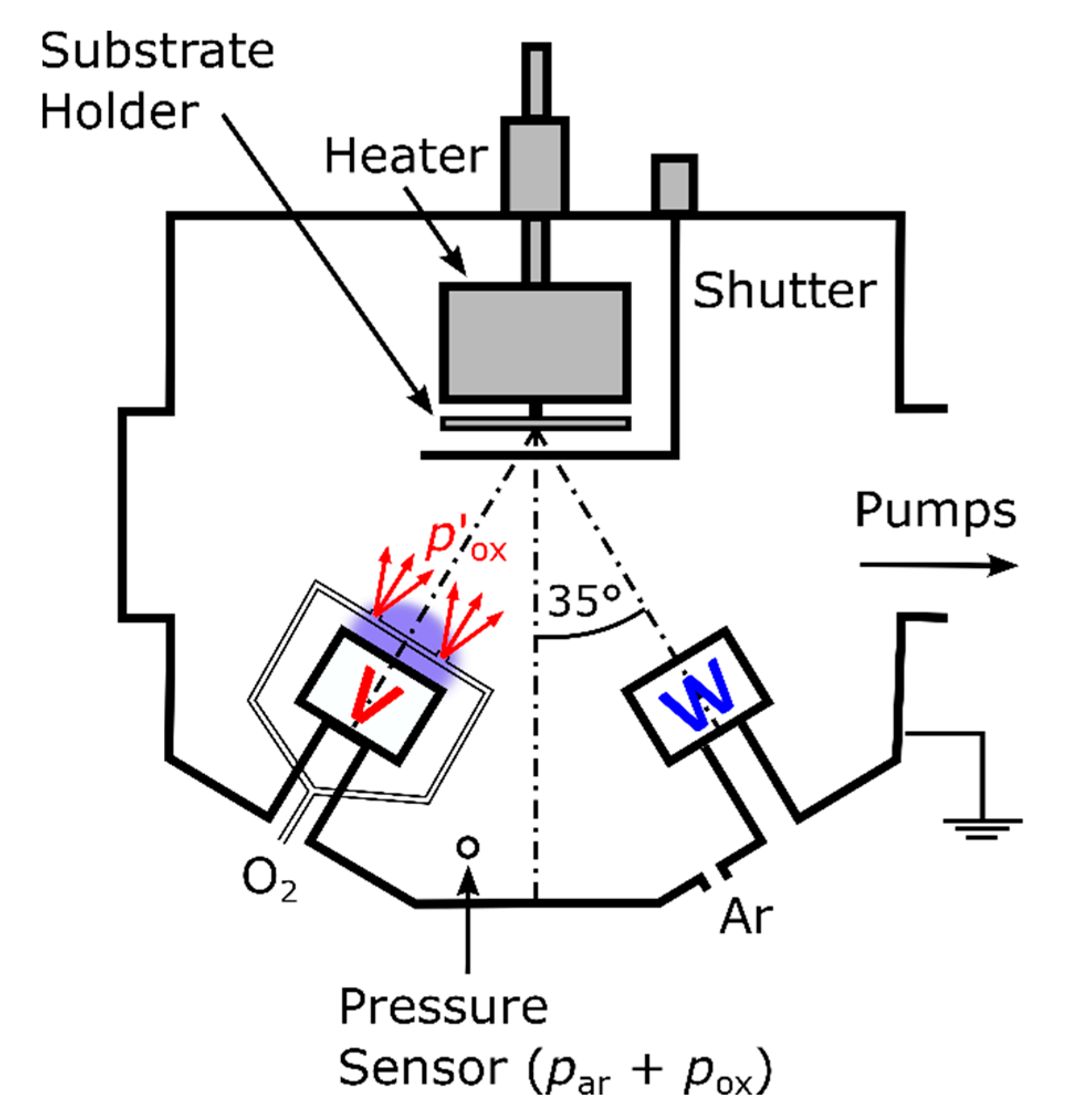
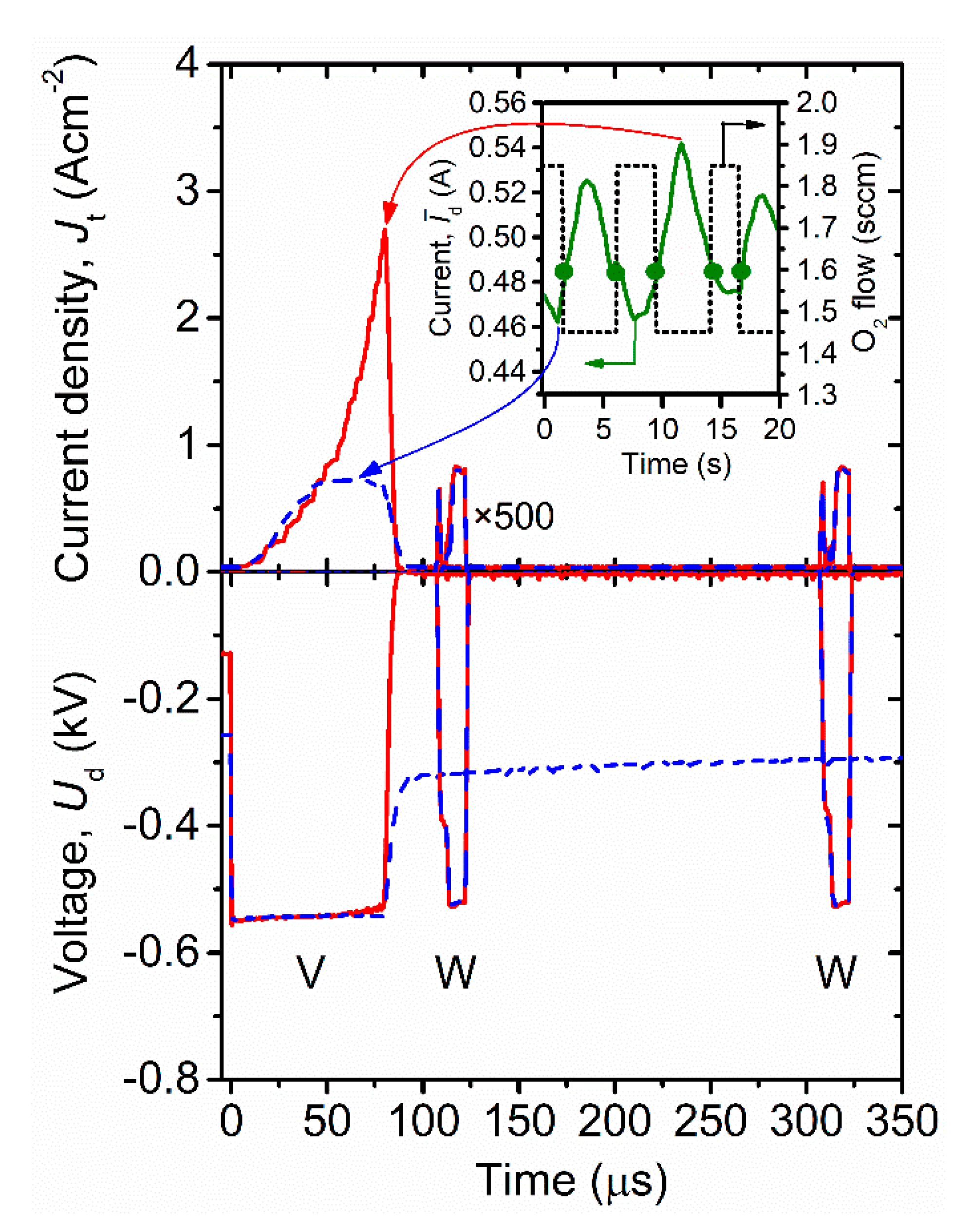
2.1. Coating Preparation

In this study, the ZrO2/V0.984W0.016O2/ZrO2 coatings were deposited onto 0.1 mm thick FG (Nippon Electric Glass Co., Ltd., Otsu, Japan) and 1 mm thick SLG substrates in argon-oxygen gas mixtures at the argon partial pressure par = 1 Pa in an ultra-high vacuum sputter device with four unbalanced magnetrons, located symmetrically around the vacuum chamber axis (ATC 2200-V AJA International Inc., Scituate, MA, USA). The stainless-steel vacuum chamber (diameter of 560 mm and length of 430 mm) was evacuated by a turbomolecular pump (1200 L·s−1) backed up with a double stage Roots pump (27 m3·h−1). The base pressure before deposition was below 10−4 Pa. The rotating (20 rpm) substrates at the distance of 145 mm from the targets were at a floating potential. The values of par and of par + pox, where pox is the oxygen partial pressure in the chamber, were measured at the chamber wall using a high-stability capacitance manometer (Baratron, Type 127, MKS, Andover, MA, USA) with an accuracy much better than 1%.
The V0.984W0.016O2 layers were deposited by controlled HiPIMS of a planar V target (99.9% purity, diameter of 50 mm and thickness of 6 mm), combined with a simultaneous pulsed dc magnetron sputtering of a planar W target (99.9% purity, diameter of 50 mm and thickness of 6 mm) at the substrate surface temperature Ts = 330 °C (see Figure 1). This Ts value was maintained during the deposition by a built-in infrared heating system calibrated using a thermocouple directly attached to the substrate surface (additional heating effect by the plasma included). The magnetron with the V target was driven by a unipolar high-power pulsed dc power supply (TruPlasma Highpulse 4002 TRUMPF Huettinger, Zielonka, Poland). In this work, the voltage pulse duration was 80 µs at a repetition frequency of 625 Hz (duty cycle of 5%) and the deposition-averaged target power density (spatially averaged over the total target area) was 13.5 W·cm−2. The magnetron with the W target was driven by a unipolar pulsed dc power supply (IAP-1010 EN Technologies Inc., Gunpo-si, Korea). The voltage pulse duration was 16 µs at a repetition frequency of 5 kHz (duty cycle of 8%) and the deposition-averaged target power density was 35 mW·cm−2.
Oxygen was admitted into the vacuum chamber via mass flow controller and two corundum conduits (Figure 1). Two O2 inlets with a diameter of 1 mm were placed symmetrically above the V target racetrack at the same distance of 20 mm from the V target surface and oriented to the substrate. The to-substrate O2 injection into the dense plasma in front of the sputtered target is very important for reactive HiPIMS depositions of oxide films [31,32]. It leads to a substantially decreased compound fraction in the target surface layer [32,33], resulting in reduced arcing, increased sputtering of metal atoms, and low production of O ions at the target [31,34,35], and to a substantially increased compound fraction in the substrate layer due to a significantly increased chemisorption flux of O atoms onto the substrate [32,33]. This is caused by a substantially (two to three times in [32]) increased local oxygen partial pressure (pox) in front of the O2 inlets and by a very high degree of dissociation of O2 molecules in the high-density plasma in front of the target.
The argon flow rate was 60 sccm corresponding to par = 1 Pa, while the total oxygen flow rate (Φox) in both conduits was not fixed but alternating between 1.45 and 1.85 sccm (see Figure 2). The moments of switching of the Φox pulses were determined during the deposition by a programmable logic controller using a pre-selected critical value of the average discharge current on the V target in a period of the power supply ( I ¯ d)cr = 0.485 A: when I ¯ d ˂ ( I ¯ d)cr, Φox = 1.85 sccm and when I ¯ d ≥ ( I ¯ d)cr, Φox = 1.45 sccm.
The basic principle of the pulsed O2 flow control is illustrated in Figure 2, which shows the time evolution of the magnetron voltage (Ud(t)) and the target current density (Jt(t)), averaged over the total target area, for both targets at the minimum (pox ≈ 0.02 Pa) and maximum (pox ≈ 0.05 Pa) value of the oxygen partial pressure in the vacuum chamber corresponding to the minimum and maximum I ¯ d, respectively, during the deposition. The much higher values of Jt(t) for the V target at the highest pox, leading to a maximum V target power density of 1.4 kW cm−2 in a pulse, can be explained [35]: (1) by a significantly enlarged flux of the O 2 + and O + ions, arising in front of the partly oxidized V target (due to a higher pox), and (2) by an increased secondary-electron emission yield of the V target with a larger compound coverage, particularly for the impacting O 2 + and O + ions [36]. A slow decrease in Ud(t) after the negative voltage pulse measured for the V target at pox ≈ 0.02 Pa (see Figure 2) is a result of a slow discharging of the power supply capacitor owing to a very low Jt(t) at the moment of the Ud pulse termination.
This feedback process control makes it possible to deliver a high power into discharge pulses without arcing on the V target surface and thus, to utilize two exclusive benefits of the HiPIMS discharges in the preparation of crystalline thermochromic VO2-based layers on unbiased non-conductive substrates at relatively low Ts [34,35]. The first benefit is highly ionized fluxes of particles with many vanadium ions onto the substrate and enhanced energies (up to 50 eV relative to grounded electrode in [34,35]) of the ions bombarding the growing films, allowing us to achieve the VO2 crystallinity at a relatively low Ts and without any substrate bias voltage. The second benefit is a very high degree of dissociation of the O2 molecules injected into the high-density plasma in front of the V target, allowing us to achieve the required VO2 stoichiometry at a low compound fraction in the V target surface layer.
The advantages of the used pulsed O2 flow control are: (1) very high process stability (no problems with inertia of the inlet system, delay of valves and sensors, and hysteresis effects) as the controller does not try to keep one value but allows for a pre-selected interval of an output variable in accordance with the control-theory literature dealing with the control of non-linear systems [37], (2) simplicity, as no additional measurement devices (such as a plasma emission monitoring system, mass spectrometer or Lambda sensor) are needed, and (3) applicability to large-area coaters as a multi-segment O2 injection control can be used.
Both the bottom and the top ZrO2 AR layers (see Figure 3) were deposited by reactive pulsed dc magnetron sputtering without ohmic heating (Ts < 60 °C). The pox was 0.12 Pa (oxide mode) at Φox = 9 sccm. The depositions were performed using an unbalanced magnetron with a planar Zr target (99.9% purity, diameter of 50 mm and thickness of 6 mm) driven by an asymmetric bipolar pulsed dc power supply (TruPlasma Bipolar 4010, TRUMPF Huettinger, Freiburg, Germany) with a reverse (positive) voltage being close to 10% of the operational (negative) voltage of 530 to 560 V during the pulses. The negative voltage pulse duration was 6.25 µs at a repetition frequency of 80 kHz (duty cycle of 50%) and the average target power density was 12.6 Wcm−2 in these negative pulses.

2.2. Coating Characterization

The W content in the metal sublattice of V0.984W0.016O2, i.e., 1.6 ± 0.6 at.%, was measured on a dedicated 290 nm thick layer (using the same substrate) in a scanning electron microscope (SU-70, Hitachi, Kyoto, Japan) using wave-dispersive spectroscopy (Magnaray, Thermo Scientific, Waltham, MA, USA) at a low primary electron energy of 7 kV. The higher thickness of the dedicated film and the low primary energy collectively facilitate using the bulk procedure for processing the data. The room-temperature (25 °C) crystal structure of both V0.984W0.016O2 and ZrO2 was characterized by X-ray diffraction (XRD) using a PANalytical X’Pert PRO diffractometer (Malvern, UK) working with a CuKα (40 kV, 40 mA) radiation at a glancing incidence of 1°.
The thickness and room-temperature (23 °C) optical constants (refractive index, n, and extinction coefficient, k) of individual layers were measured by spectroscopic ellipsometry using the J.A. Woollam Co. Inc. (Lincoln, NE, USA) VASE instrument. The measurements were performed in the wavelength (λ) range 300–2000 nm (below we present properties at λ = 550 nm, n550 and k550) at the angles of incidence of 55°, 60° and 65° in reflection. The optical model [26] consisted of the FG or SLG substrate, a bottom ZrO2 layer, a bottom intermix layer, a V0.984W0.016O2 layer, a top intermix layer, a top ZrO2 layer and a surface roughness layer. The intermix layers and half of the surface roughness layer are included in the presented thickness values. The two ZrO2 layers were expected to have the same properties and were described by the Cauchy dispersion formula. The V0.984W0.016O2 layer was described by a combination of a Cody-Lorentz oscillator with Lorentz oscillators.
The coating transmittance (T) and reflectance (R) were measured by spectrophotometry using the Agilent CARY 7000 instrument (Mulgrave, Australia) and an in-house made heat/cool cell. In the case of the thick SLG substrate, the samples in the cell were freestanding. In the case of the thin FG substrate, the samples in the cell were supported by an underlying 1 mm thick glass in order to guarantee the homogeneity of the temperature field. There was most likely a very thin air layer at some parts of the contact area between the FG substrate and the supporting glass, not only leading to an interference on FG, which is averaged out in Figures 4 and 6, but even affecting the averaged properties in one direction, as discussed in Section 3.4. The measurements were performed in the wavelength range 300–2500 nm (below we present not only the spectral dependences but also T at λ = 2500 nm, T2500) at the angle of incidence of 7° (R could not be measured at 0°; however, it has been cross-checked that the T differences resulting from this angle difference can be safely neglected) and the results were averaged over the p- and s-polarization. The coating absorption (A) was calculated as 1—TR. The measurement temperature (Tm) was varied between Tms = −10 °C and Tmm = 70 °C (between the semiconducting and the metallic state of the V0.984W0.016O2 layer, respectively). Five measurements of the spectral dependences T(λ) and R(λ), and the temperature dependence T2500(Tm) for each coating on the same substrate proved their full reproducibility.
The coating performance is quantified by means of integral luminous transmittance, reflectance and absorption (Tlum, Rlum and Alum, respectively), their modulations (ΔTlum, ΔRlum and ΔAlum), integral solar energy transmittance, reflectance and absorption (Tsol, Rsol and Asol, respectively) and again their modulations (ΔTsol, ΔRsol and ΔAsol). The quantities are defined as
T lum ( T m )   =   380 780 φ lum ( λ ) φ sol ( λ ) T ( T m ,   λ ) d λ 380 780 φ lum ( λ ) φ sol ( λ ) d λ ,
Δ T lum =   T lum ( T ms ) T lum ( T mm ) ,
T sol ( T m )   =   300 2500 φ sol ( λ ) T ( T m ,   λ ) d λ 300 2500 φ sol ( λ ) d λ ,
Δ T sol =   T sol ( T ms ) T sol ( T mm ) ,
and similarly, for the reflectance and for the absorption, where φlum is the luminous sensitivity of the human eye and φsol is the sea-level solar irradiance spectrum [38] at an air mass of 1.5.
The coating color and its temperature dependence was evaluated in the CIE XYZ color space (used to visualize the chromaticity in terms of x = X/[X + Y + Z] and y = Y/[X + Y + Z]) as well as in the related CIE L* a* b* color space (being more perceptually uniform). The evaluation was done for the CIE 1931 2° standard observer and the CIE standard daylight illuminant D65, both in transmission and in reflection (using the aforementioned T(Tm) and R(Tm), respectively, measured by spectrophotometry).

3. Results and Discussion

This section is divided into four subsections. In the first one, the design of the three-layer thermochromic ZrO2/V0.984W0.016O2/ZrO2 coatings is presented (Figure 3) and explained. In the second one, their transition temperature, lowered to 22 °C, is presented (Figure 4). The third subsection deals with the crystal structure of these coatings (Figure 5). Finally, their optical properties are presented and discussed. The spectral transmittance, reflectance, and absorption of the coatings are shown in Figure 6, and the corresponding integral quantities are given in Table 1. The colors of these thermochromic coatings are shown in Figure 7.

3.1. Coating Design

As indicated by the coating formula description, the coating design shown in Figure 3 consists of ZrO2 AR layers both below and above the thermochromic layer. Note that ZrO2 layers are being increasingly applied to architectural glass as a protective overcoat for advanced low-emissivity stacks [39]. The specific advantages of ZrO2 for the present purpose are: (1) a proper value of n, which is sufficiently close to the geometric mean of those of V0.984W0.016O2 and air (top AR layer) as well as those of V0.984W0.016O2 and FG or SLG (bottom AR layer) given in Figure 3, (2) a very small value of k in the λ range of interest (measured k550—which also confirms the ZrO2 stoichiometry—was on the order of 10−3 or lower), (3) achievable crystallinity at a low deposition temperature, which gives the bottom AR layer a second role of a template which improves the crystallinity of the thermochromic layer, and (4) high hardness (for an oxide) which gives the top AR layer the aforementioned second role of a mechanical protection of the thermochromic layer. Furthermore, the design of the coating and the pathway for its preparation is prone to maximize its environmental stability due to the densification of V0.984W0.016O2 resulting from using HiPIMS [20] and due to the dual protection [21] of V0.984W0.016O2 by both stable AR layers.
The coating performance strongly depends on the thickness of the bottom and the top AR layer (hb and ht, respectively). It has been detailed [26] and experimentally justified [25,26] that while the usual thin quarter-wavelength AR layers lead to a maximum Tlum at a very low ΔTsol, thicker three quarter-wavelength AR layers lead to maxima of both Tlum (due to the second-order interference in the visible) and ΔTsol (due to the first-order interference in the near infrared where most of the energy saving takes place). This leads to an optimum optical path length of ZrO2 corresponding to, e.g., hb = ht = 180 nm at n550 = 2.15 (value considered in [26]) and similarly for other n550 values. Figure 3 shows that first, the optical path length of ZrO2 is about the same on both FG and SLG (the coating on FG exhibits slightly lower hb and ht at slightly higher n550 and vice versa). Second, the optical path length is close to the optimum value (e.g., for the top AR layer on FG [180   ×   2.15]/[178   ×   2.09] = 104%) and consequently allows us to once again demonstrate the advantages of the aforementioned design (following the design, even more exactly, is desired for the industrialization, but this is beyond the aim of this paper).

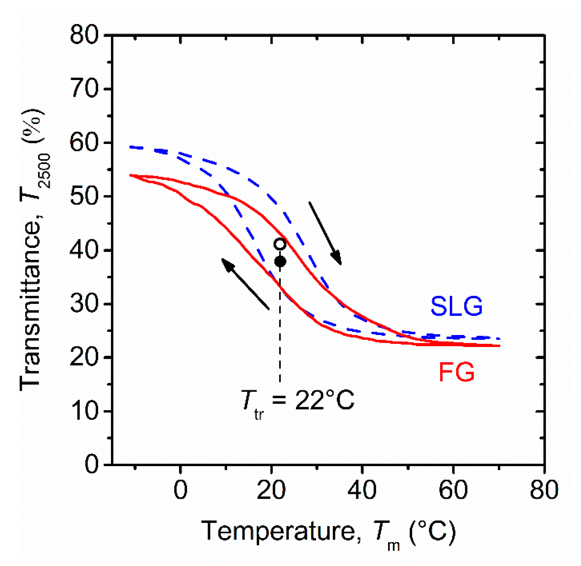
3.2. Transition Temperature

Figure 4 shows the transition temperature (Ttr) of the coatings prepared on FG and on SLG, defined as the temperature leading to a half of the total T2500 change (averaged over the heating and the cooling part of the hysteresis curve). Let us recall that the hysteresis curves, and thus also the Ttr values, are fully reproducible for these stable thermochromic coatings (see Section 2.2). It can be seen that in agreement with the same elemental composition of the active layers in both coatings (guaranteed by a rotating substrate holder; see also Figure 3 for almost substrate-independent n550 and k550 of these layers), both coatings exhibit the same Ttr = 22 °C. Doping the metal sublattice by 1.6 at.% of W decreased Ttr from 57 °C, which was exhibited by thin films of pure VO2 prepared by us using the same technique [25], i.e., at a gradient rate of −22 °C/at.% (consistent with the overview in [26]). Let us emphasize that the presented deposition technique allowed us not only to achieve a smooth and reproducible control of Ttr in itself, but it allowed us to achieve it at a preserved strength of the thermochromic effect (Section 3.4). The presented combination of a lowered Ttr with a high Tlum and ΔTsol is unlike the previously reported lowering of Ttr at the cost of a drop of ΔTsol [15,23]. Let alone those efforts to prepare VO2-based coatings onto PET foils using hydrothermal synthesis, which did not lead to similarly low Ttr at all [24,40].

3.3. Coating Structure

The crystal structure of the bottom ZrO2 layers and of the whole three-layer coatings is shown in the bottom and in the top part of Figure 5, respectively. Regarding bottom ZrO2 layers by themselves, the most important piece of information is their crystallinity in itself, confirming its role of a template layer for the growth of V0.984W0.016O2. There are mostly monoclinic ZrO2 crystals (PDF#04-013-6875 [41]), with a contribution of tetragonal ZrO2 crystals (PDF#01-081-1544 valid for ZrO1.95, particularly visible in that XRD spectrum on FG which includes also the top ZrO2 layer). Regarding V0.984W0.016O2, the most important piece of information is that there is no trace of any undesired VOx phase. All peaks are identified as diffraction peaks of either the low-temperature thermochromic phase VO2(M1) (PDF#04-003-2035) or the high-temperature thermochromic phase VO2(R) (PDF#01-073-2362). These two phases are difficult to distinguish and they are actually expected to be present simultaneously because the room-temperature XRD measurements took place almost exactly at the thermochromic transition temperature. See, e.g., the strongest peak around 2Θ = 27.8°, corresponding well to theoretical positions of the VO2(M1) (011) planes and the VO2(R) (110) planes (2Θ = 27.80° and 27.91°, respectively). In agreement with Figure 3 and Figure 4, Figure 5 also does not show any convincing difference between the two coatings and confirms the successful transfer from the SLG to the ultrathin FG substrate.

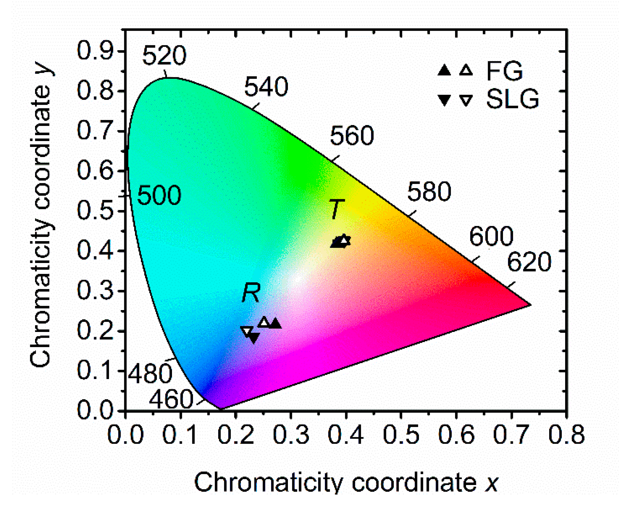
3.4. Optical Properties

The spectral T, R, and A of the coatings are shown in Figure 6a–c, respectively, and the corresponding integral quantities are given in Table 1. Figure 6a clearly shows the desired thermochromic effect by itself: a strong modulation of T in the near infrared, where it is multiplied by still a relatively strong solar irradiance in the calculation of ΔTsol according to Equations (3) and (4). This effect is combined with an almost preserved transmittance in the visible (ΔTlum as low as ≈3%), which constitutes a comparative advantage of the presented solution over other types of energy-saving coatings. Figure 6b shows the effectiveness of the antireflection layers: R drops almost to zero around 550 nm (Rlum as low as ≈7%, second-order interference which guarantees high Tlum), and again around 1650 nm (first-order interference which guarantees high ΔTsol). The positions of interference maxima of T well correspond to the positions of interference minima of R and vice versa. Furthermore, these positions are the same for both coatings, confirming the same optical path length of ZrO2 layers.
Values of the most important integral quantities measured on SLG are: Tlum approaching 50% and ΔTsol over 10%. Let us recall the application potential resulting from obtaining this result at a lowered Ttr = 22 °C. Moreover, the recent literature overview in [25] even shows that the presented Tlum and ΔTsol values are competitive with all reported values achieved at any Ttr up to 40 °C. Note Figure 6a, in which T measured on FG is slightly lower than that measured on SLG (with the complement to 100% observable as a slightly enhanced R and A). While this cannot be explained by the measured V0.984W0.016O2 thickness and properties, it can be explained as an artifact of the aforementioned (Section 2.2) very thin air layer between thin FG and the supporting thick glass during the spectrophotometry. This air layer is not included in the optimized coating design, which maximizes T and consequently may decrease the measured T below that, which is very achievable. Optical calculations which include the air layer (not shown) indicate that Tlum may in that case be underestimated by ≈4% (consistently with its measured difference shown in Table 1), at a comparatively weaker effect on ΔTsol (where the underestimations of T below and above Ttr partially cancel out).
Furthermore, Figure 6 and Table 1 collectively demonstrate how the drop in T, resulting from the transition of both coatings from the semiconducting (−10 °C) to the metallic (70 °C) state, is divided between R (actually lowered around 800 nm but strongly enhanced around 1100 nm) and A (strongly enhanced above 1100 nm). Quantitatively, ΔTsol of ≈10% corresponds to ΔRsol of ≈2% (in agreement with the effectiveness of the antireflection layers) and ΔAsol of ≈8%. This phenomenon, in particular the enhanced A leading to enhanced radiation, is important for future calculations of energy fluxes in the thermochromic coatings.
The chromaticity of the presented coatings, assuming daylight illumination from the coated side and no illumination from the backside, is shown in Figure 7. It can be seen that in transmission (smart window as seen from the inside) the coatings are yellowish, while in reflection (smart window as seen from the outside) the coatings are somewhat violet in color. From the application point of view, it is very important that the corresponding full and empty symbols in Figure 7 are very close to each other, i.e., that there is a negligible chromaticity change resulting from the thermochromic transition. This is consistent with negligible changes of optical properties in the visible as shown in Figure 6. Furthermore, the corresponding triangles up and triangles down in Figure 7 are almost overlapping (in transmission) or very close to each other (in reflection), which constitutes another confirmation of the successful transfer from SLG to ultrathin FG. The color coordinates in the perceptually uniform CIE L* a* b* color space (chromaticity given by a* and b* and lightness given by L* between 0 and 100), averaged over the corresponding four datapoints in each case, include L* = 73, a* = −4, b* = 39 in transmission and L* = 33, a* = 16, b* = −30 in reflection. Note that in agreement with the non-linear nature of L*, both its values are well above the values of Tlum and Rlum, respectively. All the details presented in Figure 6 and Figure 7 complement the basic information given about this type of coatings in [25] and are relevant for the optimization and usage of smart windows.

4. Conclusions

We have presented and explained a scalable sputter deposition technique for the preparation of strongly thermochromic ZrO2/V0.984W0.016O2/ZrO2 coatings on ultrathin FG and standard SLG at a relatively low substrate surface temperature (330 °C) and without any substrate bias voltage. The V0.984W0.016O2 layers were deposited by a controlled HiPIMS of a V target, combined with a simultaneous pulsed dc magnetron sputtering of a W target (doping of VO2 by W to reduce the transition temperature without any degradation of thermochromic properties). The coatings exhibit a transition temperature of 22 °C, a luminous transmittance approaching 50%, a modulation of the solar energy transmittance over 10% and a temperature-independent color. Such a combination of properties, together with the relatively low deposition temperature, has not yet been published by other teams for thermochromic VO2-based coatings in the literature. This deposition technique is compatible with the existing magnetron sputtering systems in glass production lines and in roll-to-roll deposition devices. Its successful transfer to a large-scale roll-to-roll device producing coatings on ultrathin FG would open up the possibility for new smart-window applications of thermochromic VO2-based coatings, such as the retrofitting of existing low-efficiency glass windows and the manufacturing of new high-efficiency insulated glass units with multiple functionalities.

Author Contributions

Conceptualization, J.V., M.F., and J.F.; investigation, T.B., J.H., S.H., and R.Č.; methodology, J.V.; validation, J.S.; visualization, T.B.; data curation, T.B.; writing–original draft preparation, J.V. and J.H.; writing–review and editing, J.V. and J.H.; funding acquisition, J.V. All authors have read and agreed to the published version of the manuscript.

Funding

This research was funded from The European Union’s Horizon 2020 Research and Innovation Programme under Grant Agreement No. 869929, Project “Switch2Save”.

Conflicts of Interest

The authors declare no conflict of interest.

References

  1. Omer, A.M. Energy, environment and sustainable development. Renew. Sust. Energ. Rev. 2008, 12, 2265–2300. [Google Scholar] [CrossRef]
  2. USA Department of Energy. 2011 Buildings Energy Data Book; USA Department of Energy: Washington, DC, USA, 2012.
  3. Granqvist, C.G. Recent progress in thermochromics and electrochromics: A brief survey. Thin Solid Films 2016, 614, 90–96. [Google Scholar] [CrossRef]
  4. Morin, F.J. Oxides Which Show a Metal-to-Insulator Transition at the Neel Temperature. Phys. Rev. Lett. 1959, 3, 34–36. [Google Scholar] [CrossRef]
  5. Gao, Y.; Luo, H.; Zhang, Z.; Kang, L.; Chen, Z.; Du, J.; Kanehira, M.; Cao, C. Nanoceramic VO2 thermochromic smart glass: A review on progress in solution processing. Nano Energy 2012, 1, 221–246. [Google Scholar] [CrossRef]
  6. Wang, S.; Liu, M.; Kong, L.; Long, Y.; Jiang, X.; Yu, A. Recent progress in VO2 smart coatings: Strategies to improve the thermochromic properties. Prog. Mater. Sci. 2016, 81, 1–54. [Google Scholar] [CrossRef]
  7. Li, M.; Magdassi, S.; Gao, Y.; Long, Y. Hydrothermal Synthesis of VO2 Polymorphs: Advantages, Challenges and Prospects for the Application of Energy Efficient Smart Windows. Small 2017, 13, 1701147. [Google Scholar] [CrossRef]
  8. Xu, F.; Cao, X.; Luo, H.; Jin, P. Recent advances in VO2-based thermochromic composites for smart windows. J. Mater. Chem. C 2018, 6, 1903–1919. [Google Scholar] [CrossRef]
  9. Chang, T.-C.; Cao, X.; Bao, S.-H.; Ji, S.-D.; Luo, H.-J.; Jin, P. Review on thermochromic vanadium dioxide based smart coatings: From lab to commercial application. Adv. Manuf. 2018, 6, 1–19. [Google Scholar] [CrossRef] [Green Version]
  10. Fortier, J.-P.; Baloukas, B.; Zabeida, O.; Klemberg-Sapieha, J.E.; Martinu, L. Thermochromic VO2 thin films deposited by HiPIMS. Sol. Energy Mater. Sol. Cells 2014, 125, 291–296. [Google Scholar] [CrossRef]
  11. Aijaz, A.; Ji, Y.-X.; Montero, J.; Niklasson, G.A.; Granqvist, C.G.; Kubart, T. Low-temperature synthesis of thermochromic vanadium dioxide thin films by reactive high power impulse magnetron sputtering. Sol. Energy Mater. Sol. Cells 2016, 149, 137–144. [Google Scholar] [CrossRef]
  12. Sun, G.; Cao, X.; Li, X.; Bao, S.; Li, N.; Liang, M.; Gloter, A.; Gu, H.; Jin, P. Low-temperature deposition of VO2 films with high crystalline degree by embedding multilayered structure. Sol. Energy Mater. Sol. Cells 2017, 161, 70–76. [Google Scholar] [CrossRef]
  13. Chang, T.; Cao, X.; Li, N.; Long, S.; Gao, X.; Dedon, L.R.; Sun, G.; Luo, H.; Jin, P. Facile and Low-Temperature Fabrication of Thermochromic Cr2O3/VO2 Smart Coatings: Enhanced Solar Modulation Ability, High Luminous Transmittance and UV-Shielding Function. ACS Appl. Mater. Interfaces 2017, 9, 26029–26037. [Google Scholar] [CrossRef] [PubMed]
  14. Saeli, M.; Piccirillo, C.; Parkin, I.P.; Binions, R.; Ridley, I. Energy modelling studies of thermochromic glazing. Energy Build. 2010, 42, 1666–1673. [Google Scholar] [CrossRef]
  15. Hu, L.; Tao, H.; Chen, G.; Pan, R.; Wan, M.; Xiong, D.; Zhao, X. Porous W-doped VO2 films with simultaneously enhanced visible transparency and thermochromic properties. J. Sol-Gel Sci. Technol. 2015, 77, 85–93. [Google Scholar] [CrossRef]
  16. Baloukas, B.; Loquai, S.; Martinu, L. VO2-based thermally active low emissivity coatings. Sol. Energy Mater. Sol. Cells 2018, 183, 25–33. [Google Scholar] [CrossRef]
  17. Wang, N.; Goh, Q.S.; Lee, P.L.; Magdassi, S.; Long, Y. One-step hydrothermal synthesis of rare earth/W-codoped VO2 nanoparticles: Reduced phase transition temperature and improved thermochromic properties. J. Alloy. Compd. 2017, 711, 222–228. [Google Scholar] [CrossRef]
  18. Dietrich, M.K.; Kuhl, F.; Polity, A.; Klar, P.J. Optimizing thermochromic VO2 by co-doping with W and Sr for smart window applications. Appl. Phys. Lett. 2017, 110, 141907. [Google Scholar] [CrossRef]
  19. Lu, L.; Wu, Z.; Ji, C.; Song, M.; Feng, H.; Ma, X.; Jiang, Y. Effect of Fe doping on thermochromic properties of VO2 films. J. Mater. Sci. Mater. Electron. 2018, 29, 5501–5508. [Google Scholar] [CrossRef]
  20. Loquai, S.; Baloukas, B.; Klemberg-Sapieha, J.E.; Martinu, L. HiPIMS-deposited thermochromic VO2 films with high environmental stability. Sol. Energy Mater. Sol. Cells 2017, 160, 217–224. [Google Scholar] [CrossRef]
  21. Chang, T.; Cao, X.; Dedon, L.R.; Long, S.; Huang, A.; Shao, Z.; Li, N.; Luo, H.; Jin, P. Optical design and stability study for ultrahigh-performance and long-lived vanadium dioxide-based thermochromic coatings. Nano Energy 2018, 44, 256–264. [Google Scholar] [CrossRef]
  22. Long, S.; Cao, X.; Li, N.; Xin, Y.; Sun, G.; Chang, T.; Bao, S.; Jin, P. Application-oriented VO2 thermochromic coatings with composite structures: Optimized optical performance and robust fatigue properties. Sol. Energy Mater. Sol. Cells 2019, 189, 138–148. [Google Scholar] [CrossRef]
  23. Shen, N.; Chen, S.; Chen, Z.; Liu, X.; Cao, C.; Dong, B.; Luo, H.; Liu, J.; Gao, Y. The synthesis and performance of Zr-doped and W–Zr-codoped VO2 nanoparticles and derived flexible foils. J. Mater. Chem. A 2014, 2, 15087–15093. [Google Scholar] [CrossRef]
  24. Dai, L.; Chen, S.; Liu, J.; Gao, Y.; Zhou, J.; Chen, Z.; Cao, C.; Luo, H.; Kanehira, M. F-doped VO2 nanoparticles for thermochromic energy-saving foils with modified color and enhanced solar-heat shielding ability. Phys. Chem. Chem. Phys. 2013, 15, 11723–11729. [Google Scholar] [CrossRef] [PubMed]
  25. Kolenatý, D.; Vlček, J.; Bárta, T.; Rezek, J.; Houška, J.; Haviar, S. High-performance thermochromic VO2-based coatings with a low transition temperature deposited on glass by a scalable technique. Sci. Rep. 2020, 10, 11107. [Google Scholar] [CrossRef]
  26. Houska, J.; Kolenaty, D.; Vlcek, J.; Barta, T.; Rezek, J.; Cerstvy, R. Significant improvement of the performance of ZrO2/V1−xWxO2/ZrO2 thermochromic coatings by utilizing a second-order interference. Sol. Energy Mater. Sol. Cells 2019, 191, 365–371. [Google Scholar] [CrossRef]
  27. Gudmundsson, J.T. On reactive high power impulse magnetron sputtering. Plasma Phys. Control. Fusion 2015, 58, 014002. [Google Scholar] [CrossRef] [Green Version]
  28. Junghähnel, M.; Westphalen, J. Processing on flexible glass—Challenges and opportunities. SVC Bull. Fall/Winter 2017, 31–39. [Google Scholar]
  29. Junghähnel, M.; Fahlteich, J. Thin-film deposition on flexible glass by plasma processes. In Flexible Glass: Enabling Thin, Lightweight, and Flexible Electronics, 1st ed.; Garner, S.M., Ed.; Scrivener Publishing LLC: Beverly, CA, USA, 2017; pp. 129–180. [Google Scholar]
  30. Fahland, M.; Zywitzki, O.; Modes, T.; Vondkar, K.; Werner, T.; Ottermann, C.; Berendt, M.; Pollack, G. Roll-to-roll sputtering of indium tin oxide layers onto ultrathin flexible glass. Thin Solid Films 2019, 669, 56–59. [Google Scholar] [CrossRef]
  31. Vlček, J.; Rezek, J.; Houska, J.; Kozak, T.; Kohout, J. Benefits of the controlled reactive high-power impulse magnetron sputtering of stoichiometric ZrO2 films. Vacuum 2015, 114, 131–141. [Google Scholar] [CrossRef]
  32. Kozák, T.; Vlček, J. A parametric model for reactive high-power impulse magnetron sputtering of films. J. Phys. D: Appl. Phys. 2016, 49, 055202. [Google Scholar] [CrossRef]
  33. Kozák, T.; Vlček, J. Dynamics of processes during the deposition of ZrO2 films by controlled reactive high-power impulse magnetron sputtering: A modelling study. J. Appl. Phys. 2017, 122, 043304. [Google Scholar] [CrossRef]
  34. Vlček, J.; Kolenatý, D.; Houška, J.; Kozák, T.; Čerstvý, R. Controlled reactive HiPIMS—Effective technique for low-temperature (300 °C) synthesis of VO2 films with semiconductor-to-metal transition. J. Phys. D: Appl. Phys. 2017, 50, 38LT01. [Google Scholar] [CrossRef] [Green Version]
  35. Vlček, J.; Kolenatý, D.; Kozák, T.; Houška, J.; Čapek, J.; Kos, Š. Ion-flux characteristics during low-temperature (300 °C) deposition of thermochromic VO2 films using controlled reactive HiPIMS. J. Phys. D: Appl. Phys. 2019, 52, 025205. [Google Scholar] [CrossRef]
  36. Aiempanakit, M.; Aijaz, A.; Lundin, D.; Helmersson, U.; Kubart, T. Understanding the discharge current behavior in reactive high power impulse magnetron sputtering of oxides. J. Appl. Phys. 2013, 113, 133302. [Google Scholar] [CrossRef]
  37. Bechhoefer, J. Feedback for physicists: A tutorial essay on control. Rev. Mod. Phys. 2005, 77, 783–836. [Google Scholar] [CrossRef] [Green Version]
  38. Available online: http://rredc.nrel.gov/solar/spectra/am1.5/; http://hyperphysics.phy-astr.gsu.edu/hbase/vision/efficacy.html; (accessed on 14 June 2016).
  39. Oberste-Berghaus, J.; Van Nuffel, R.; Gobin, G.; De Jaeger, K.; Das, A.; De Bosscher, W. Film properties of zirconium oxide top layers from rotatable targets. In Proceedings of the 58th Annual Technical Conference Proceedings of SVC 2015, Santa Clara, CA, USA, 25–30 April 2015; pp. 228–234. [Google Scholar]
  40. Chen, Z.; Gao, Y.; Kang, L.; Cao, C.; Chen, S.; Luo, H. Fine crystalline VO2 nanoparticles: Synthesis, abnormal phase transition temperatures and excellent optical properties of a derived VO2 nanocomposite foil. J. Mat. Chem. A 2014, 2, 2718–2727. [Google Scholar] [CrossRef]
  41. The International Centre for Diffraction Data. PDF-4+ Database; The International Centre for Diffraction Data: Newtown Square, PA, USA, 2015. [Google Scholar]
Figure 1. Schematic diagram of the magnetron sputter device showing two magnetrons with V and W targets, located in opposite positions, which were used for the deposition of the active V0.984W0.016O2 layers. Two O2 inlets were placed 20 mm from the V target surface and oriented to the substrate. Positions of the pressure sensor and the Ar inlet in the vacuum chamber wall are also shown. An increased local value of the oxygen partial pressure due to the O2 injection is denoted as pox.
Coatings 10 01258 g001
Figure 2. Waveforms of the magnetron voltage (Ud) and the target current density (Jt) for preset deposition-averaged target power densities of 13.5 Wcm−2 and 35 mWcm−2 for V and W target, respectively, during a deposition of the V0.984W0.016O2 layers (the Jt values for W target are magnified 500 times). Time evolution of the average discharge current on the V target in a period of its power supply ( I ¯ d) during the deposition is shown in the inset. A pre-selected critical value ( I ¯ d)cr = 0.485 A determining the switching between the oxygen flow rates Φox = 1.45 sccm and Φox = 1.85 sccm is marked by dots.
Coatings 10 01258 g002
Figure 3. The three-layer thermochromic VO2-based coatings on ultrathin flexible glass (a) and soda-lime glass (b) substrates investigated in this paper. Here, hb, h, and ht represent the thickness of the bottom ZrO2 layer, the thickness of the active V0.984W0.016O2 layer, and the thickness of the top ZrO2 layer, respectively. The refractive index (n550) and extinction coefficient (k550) at the wavelength of 550 nm of all layers were measured at Tm = 23 °C.
Coatings 10 01258 g003
Figure 4. Temperature (Tm) dependence of the transmittance (T2500) at 2500 nm for the ZrO2/V0.984W0.016O2/ZrO2 coatings deposited on 0.1 mm thick FG and 1 mm thick SLG substrates (Figure 3). The transition temperature Ttr = 22 °C is presented.
Coatings 10 01258 g004
Figure 5. X-ray diffraction patterns taken at Tm = 25 °C from the ZrO2 (172 nm)/V0.984W0.016O2 (71 nm)/ZrO2 (178 nm) coating on 0.1 mm thick FG substrate and the ZrO2 (175 nm)/V0.984W0.016O2 (79 nm)/ZrO2 (190 nm) coating on 1 mm thick SLG substrate. For comparison, the X-ray diffraction patterns from the corresponding ZrO2 layers with the thickness hb = 172 nm and 175 nm are given. The main diffraction peaks of VO2(R), VO2(M1), ZrO2(m) and ZrO2(t) are marked.
Coatings 10 01258 g005
Figure 6. Spectral transmittance (T), reflectance (R) and absorption (A) at an angle of incidence of 7° for the ZrO2/V0.984W0.016O2/ZrO2 coatings on 0.1 mm thick FG (solid and dashed lines) and 1 mm thick SLG (dash-dotted and dotted lines) substrates at Tms = −10 °C (significantly below Ttr = 22 °C) and Tmm = 70 °C (significantly above Ttr = 22 °C). The boundaries of the shaded areas represent the luminous sensitivity of the human eye (φlum) in panel (a), and the sea-level solar irradiance spectrum (φsol) at an air mass of 1.5 in panels (b,c), normalized to maxima of 100%.
Coatings 10 01258 g006
Figure 7. Chromaticity of the coatings shown in the CIE xy chromaticity diagram. There are data below Ttr (full symbols) and above Ttr (empty symbols), obtained on the ultrathin FG substrate (triangles up) and SLG substrate (triangles down) using the transmittance (T) and the reflectance (R) presented in Figure 6.
Coatings 10 01258 g007
Table 1. Thermochromic properties of the ZrO2/V0.984W0.016O2/ZrO2 coatings deposited on 0.1 mm thick flexible glass (FG) and 1 mm thick soda-lime glass (SLG) substrates are presented. For the coatings on the FG substrate, the measured T values may be underestimated by up to 4% and the measured R values may be overestimated by approximately 1%, owing to the effect of the very thin air layer arising between the FG substrate and an underlying supporting 1 mm thick SLG used during the measurements (see Section 2.2).
SubstrateTlum (Tms)
(%)
Tlum (Tmm)
(%)
ΔTlum
(%)
Tsol (Tms)
(%)
Tsol (Tmm)
(%)
ΔTsol
(%)
FG45.742.23.539.630.09.6
SLG48.645.53.143.132.410.7
SubstrateRlum (Tms)
(%)
Rlum (Tmm)
(%)
ΔRlum
(%)
Rsol (Tms)
(%)
Rsol (Tmm)
(%)
ΔRsol
(%)
FG8.28.3−0.116.618.9−2.3
SLG6.47.1−0.715.116.9−1.8
SubstrateAlum (Tms)
(%)
Alum (Tmm)
(%)
ΔAlum
(%)
Asol (Tms)
(%)
Asol (Tmm)
(%)
ΔAsol
(%)
FG46.149.5−3.443.851.1−7.3
SLG45.047.4−2.441.850.7−8.9
Publisher’s Note: MDPI stays neutral with regard to jurisdictional claims in published maps and institutional affiliations.

