Article

Microstructure and Rutherford Backscattering Spectrometry of Hard/Lubricant Mo-Ti-Al-N Multilayered Coatings Prepared by Multi-Arc Ion Plating at Low Substrate Rotation

1
School of Physics and Technology, Lingnan Normal University, Zhanjiang 524048, China
2
Department of Space Technology, Utkin Ryazan State Radio Engineering University, Ryazan 390005, Russia
3
School of Physics and Technology, Wuhan University, Wuhan 430072, China
4
Department of Applied Sciences, National Textile University, Sheikhupura Road, Faisalabad 37610, Pakistan
5
Institute of Ion-Plasma and Laser Technologies, Academy of Sciences of Uzbekistan, Tashkent 700135, Uzbekistan
6
School of Computer Science and Information Engineering, Hubei University, 368 Youyi Ave, Wuhan 430062, China
*
Authors to whom correspondence should be addressed.
Coatings 2020, 10(2), 101; https://doi.org/10.3390/coatings10020101
Submission received: 2 October 2019 / Revised: 19 January 2020 / Accepted: 21 January 2020 / Published: 23 January 2020

Abstract

:
To develop the hard and self-lubricating coatings applied for the industrial dry-cutting and die-casting machining tool fields, a series of MoTiAlN/MoN/Mo multilayered coatings were deposited on Si substrates under low substrate rotation by cathodic multi-arc ion plating. XRD, SEM, TEM, RBS, nanoindentation, and tribology tester were used to monitor the phase structure, morphology, component, nanohardness, and friction coefficient of the coatings. It was found that the coatings deposited at various substrate rotations comprised paramount cubic B1 structure TiAlN and Mo2N phases. The micrographs confirmed that the mean modulation period and total physical thickness of multilayered TiAlN/Mo2N coatings with a sharp interface fabricated at 2 revolutions per minute (rpm) were 26 nm and 1.15 μm. The mean nanohardness and friction coefficient were ca. 30 GPa and 0.4, respectively. RBS results along with the SIMNRA code allowed to estimate the total atomic concentrations and the physical thickness of individual sublayer as well as the modulation period of multilayered coatings, which demonstrated an efficiency of this approach for characterization of nano-multilayered structures.

1. Introduction

In the past several decades, CrN and TiN films have been acting as the first-generation industrial protective hard coatings for dry, high-temperature, and high-speed cutting tools as well as for die casting [1,2,3,4,5]. Much attention was devoted to the fabrication of multicomponent layers composed of, at least, two alternating nano-scale sublayers with the modulation period defined by their thicknesses. Such multilayers with various modulation periods or hierarchical structures are also called the superlattice films [6]. Among them, the polynary nitrogen-based composite coatings stand out for excellent mechanical, tribological, and physicochemical properties like corrosion resistance [7], wear resistance [8,9], and high-temperature oxidation resistance [10,11]. Owing to that, these coatings have become one of the most promising functional materials in the field of up-to-date industrial cutting and casting tools.
In practice, polynary nitrogen-based multilayer coatings fabricated by means of physical vapor deposition (PVD) exhibit more superior mechanical properties and thermal stability as compared with similar monolayer coatings. Magnetron sputtering has been widely employed to fabricate a large variety of multilayered films due to its low deposition temperature, high membrane density, and great advantage to produce small modulation period beneath 10 nm with a low cost in comparison with chemical vapor deposition and other high-cost epitaxial growth techniques. Yao et al. [12] designed the magnetron sputtering system featuring unbalance mode for AlN deposition along with balance mode for TiN deposition and produced TiN/AlN superlattice films with different modulation periods ranging from 2.4 to 67.6 nm, thereof, the optimized periods beneath 3.6 nm were found due to this such films exhibited extremely high hardness, excellent adhesion and wear performance as compared with single-layer TiN films. It was proved that TiN/(Ti, Al)N multilayer coatings possessed higher hardness, lower brittleness and better cutting performance than (Ti, Al)N monolayer coating produced by Chen et al. [13]. For multi-arc ion plating technique, the feature in carrying out a high deposition rate to obtain large batches of micron-thickness industrial coatings has been widely accepted. Furthermore, an increasing number of research groups have exploited the combined multi-arc ion plating and magnetron sputtering technique for synthesis of high-quality multilayer films [14,15,16,17].
TiAlN coatings were called-for scuff protection of cutting tool and microelectronic contact materials due to high hardness, corrosion resistance, and thermal stability, but their friction coefficients are a bit higher usually up to 0.8–0.9 at high temperature [18,19,20]. When Mo was introduced into the coatings forming TiAlN/MoN composite structure, the friction coefficient could decrease to 0.3–0.4 [21]. Similarly, CrN coatings exhibited a rather high friction coefficient of 0.6–0.8 in atmosphere, whereas it could be decreased to 0.3–0.4 in CrN/Mo2N multilayered structures after the addition of Mo into the coatings [22]. Molybdenum or molybdenum nitride films have corroborated a low wear rate owing to their excellent self-lubricating effect within a wide temperature range [23,24]. In addition, the formation of molybdenum oxides in the coatings, like MoO3 reported by Koshy et al. [25], is responsible for the first-rate tribological behavior.
The previous studies have been focused upon a few known key findings in the field of multilayered films such as (i) super hardness resulted from the internal fine-grain strengthening and blocking effect of interface to dislocation; (ii) corrosion resistance improved by reducing the porousness of a variety of alternating sublayers; and (iii) enhanced wear performance due to the existence of massive interfacial structures [26,27,28]. Therefore, the synthesis of polynary nitrogen-based composite coatings can ensure not only comprehensive implementation of above-mentioned advantages, but also attached the coatings self-lubricated features via an introduction of Mo into the coatings’ structure.
The properties of nanosized multilayers strongly depend on microstructure, thickness, and composition of each sublayer. Besides the conventional characterization techniques like X-ray diffraction (XRD), energy-dispersive X-ray spectroscopy (EDS), scanning electron microscopy (SEM), transmission electron microscopy (TEM), secondary ion mass spectrometry (SIMS), and X-ray photoelectron spectroscopy (XPS), Rutherford backscattering spectrometry (RBS) can be employed to detect the chemical composition, physical thickness, and element depth profiles in the materials [29,30]. Hans et al. [31,32] made full use of incorporated RBS and elastic recoil detection analysis (ERDA) method to study the chemical modulation induced by substrate rotation for Cr-Al-N-O coatings synthesized by arc-ion plating and the chemical composition of TiAlN thin films in comparison with laser-assisted atom probe tomography (APT) characterization. Tavares et al. [33,34] revealed that RBS can provide extremely accurate measurements of the interface architectural features for Ti0.4Al0.6N/Mo multilayer films fabricated by reactive magnetron sputtering and proved that an interlayer atomic mixing of the multilayered films can induce a great interfacial roughness. RBS analysis is not only a non-destructive method, but also using an incident proton beam or 4He2+ ion beam at an energy of 1–3 MeV can measure elemental depth distributions within the larger range than in case of EDX and XPS.
In the present work, the ion-beam enhanced cathodic arc plating equipped with a hollow cathode ion source was used to fabricate Mo-Ti-Al-N nanocomposite coatings at a low rotating speed based on one-fold rotation mode. The practical requirements allow for selecting such low substrate rotation to deposit the coatings. As compared to magnetron sputtering, high deposition rate and excellent diffraction capacity of multi-arc ion plating technique can save the deposition time for arbitrary shaped substrates, but the high substrate temperature likely leads to a dramatic interface atomic diffusion into the coatings [35]. On the other hand, low substrate rotating speed is available to prepare nano-multilayer with thick bilayers where interface atomic diffusion possibly exists, but cannot result in a sharp reduction of hardness of the coatings. Combined with the conventional hardness, tribological, and morphological characterizations, physical thickness as well as the modulation period of as-deposited coatings have been quantitatively evaluated by RBS using the SIMNRA fitting code which is a versatile tool in fitting data for various ion-beam analytical techniques including RBS, non-RBS, ERDA, and nuclear reaction analysis (NRA) by ensuring compositional, depth-profiling, structural, and interfacial characteristics of the samples [36,37]. It is supposed that such approach could be a proper supplement for microstructural analysis, particularly interfacial structure of multilayered films in comparison with the results of high-resolution transmission electron microscopy (HRTEM).

2. Experimental

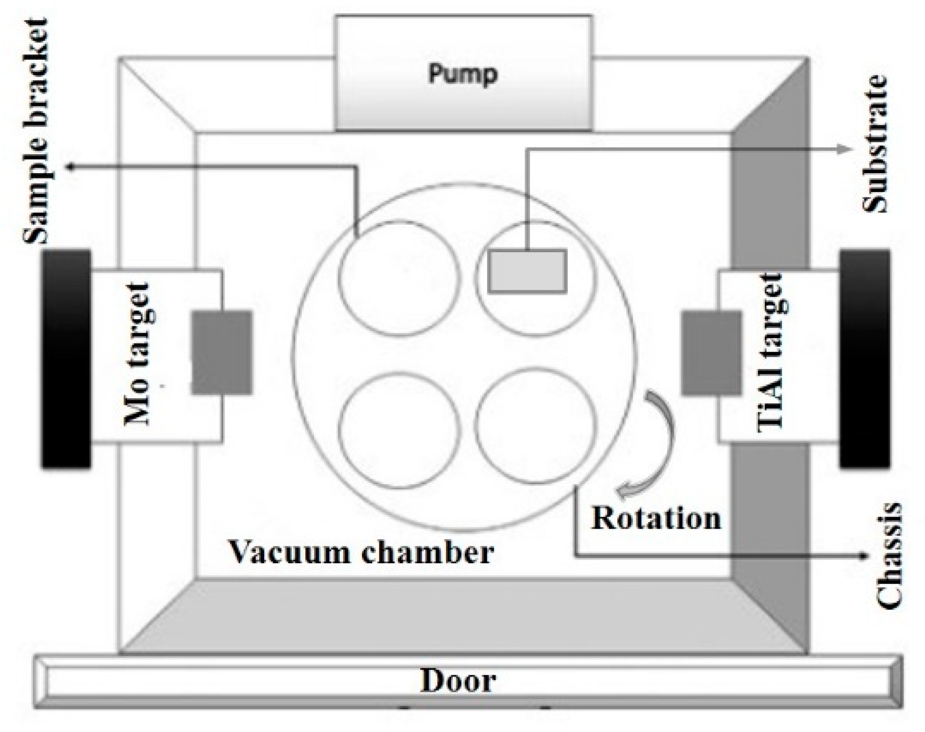
2.1. Fabrication of the Coatings

A pure Mo target (99.9%) and Ti-Al composite target (Ti 70 at.% with a purity of 99.9%) were selected as the cathodic evaporation targets for the fabrication of Mo-Ti-Al-N nanocomposite coatings on the surface of single crystal Si (100) substrates of 10 × 10 × 0.5 mm3 in size by cathodic arc ion plating. In order to improve the evaporation efficiency of refractory Mo target, a hollow cathodic arc source of ion-beam enhanced arc plating was utilized. Figure 1 shows the schematic diagram of the deposition system. The vacuum chamber was 540 × 300 × 400 mm3 in volume, and the minimum axial distance between the cathodic target and the substrate was approximately 225 mm. Two cathodic targets were mounted on the internal wall against each other at an axial distance of 492 mm, and Si substrates were vertically fixed on the sample bracket. In the course of the deposition, the chassis was continuously clockwise rotated in one-fold rotation mode. The deposition system was detailed elsewhere [21].
Prior to deposition, Si wafers were put into acetone solution, then being immersed in hot alkaline baking soda to carry out an ultrasonic cleaning for 20 min to remove surface contamination. Finally, the wafers were repeatedly washed out with deionized water and dried with pure N2 flow.
The deposition process was divided into three stages: (i) after fixing Si substrates onto the sample bracket, the vacuum chamber was pumped out to better than 2 × 10⁻³ Pa, and a successive Ar+ ions bombardment to the substrates for 20 min was conducted, where a duty cycle of 80% negative bias voltage of 800 V was applied; (ii) the turning on the power of Mo cathodic target at 6 × 10⁻² Pa after improving Ar flux rate, the processing parameters of a pure Mo layer were: 200 V negative bias voltage and 70 A target current for 8 min, then continuing to increase N2 flux up to 40 sccm for 10 min to deposit MoN interlayer, when the working pressure was stabilized at 0.5 Pa; (iii) the turning on the power of Ti-Al composite and a fine turn of N2 flux to maintain the working pressure in the chamber at 2.5 Pa, the precise controlling of Mo target current at the level of 80 A and Ti-Al target current to 60 A, while the negative bias voltage of the substrates was at 200 V and the depositing time of Mo-Ti-Al-N coatings was 20 min. It should be noted that before the deposition the substrates were heated to 300 °C, the rotation speed of the substrates was chosen in the range of 1–3 rpm, and total duration of the deposition was approximately 60 min. The deposition parameters were recited in Table 1.

2.2. Characterization of the Coatings

The phase structure of Mo-Ti-Al-N composite coatings was measured by a D8 advance X-ray diffractometer from Bruker AXS (Billerica, MA, USA) using Cu Kα radiation (λ = 0.154060 nm). The diffraction angle 2θ ranging from 30°–70° at a step of 0.02° in θ–2θ geometry was used. The surface morphological and cross-sectional images were acquired by a field emission scanning electron microscope Sirion FEG SEM by FEI (Hillsboro, OR, USA) having a maximum electron acceleration voltage of 20 kV. The HRTEM by a JEOL JEM-2010 (Tokyo, Japan) was employed to detect the microstructure features of the coatings in terms of micrographs and selected area electron diffraction (SAED) pattern. The element composition of the coatings was measured by an EDAX genesis 7000 EDS (Rotterdam, Netherlands).
Nanohardness and Young’s modulus of the coatings were assessed by the nanoindentation (G200, Agilent Technologies, Santa Clara, CA, USA) using a continuous stiffness measurement (CSM) mode. During the test, there was a three-side Berkovich-shaped indenter mounted with a tip radius of 60 nm and the maximum indentation depth was set at 0.1 μm. The resolution of loading system and displacement system was 50 nN and 0.04 nm, respectively. For each sample, six indentations along with the loading-displacement data were recorded with statistical averaging. The tribological behavior was evaluated on a MS-T3000 ball-on-disk tester, where a rigid Si3N4 ball at a diameter of 3 mm as the mating materials slide in air at room temperature with a relative humidity of 60% was used. During the test, it took 30 min to keep a continuous speed, when an average sliding speed of the ball was set at 0.02 m/s and 5 N contact loads were applied. The final friction coefficients were achieved in that time interval.
RBS analysis was carried out by means of a double 1.7 MV Tandetron accelerator (Ionx, GIC 4117, Detroit, MI, USA) in Wuhan University. The incident 7Li2+ ion beams were directed orthogonally to the sample surface and the in-plane sum of incident, exit, and backscattering angles were 180° in accordance with IBM geometry [38], as illustrated in Figure 2. 2.42 and 1.52 MeV 7Li2+ ion beams as projectiles were introduced to impinge on the surface of the sample perpendicularly with ion current of 5 nA and a circular beam spot of 1.5 mm in diameter. About 3 μC ion fluxes were monitored with a beam, and the scattered ions were collected by a passivated implanted planar silicon detector (model no. FD150-15-300RM by Canberra Industries, Meriden, CT, USA) with an energy resolution of 15 keV for α particles, which was settled at a backscattering angle of 170° in a vacuum chamber under 5 × 10⁻⁴ Pa. The RBS spectra acquired by a multichannel analyzer were exported to SIMNRA 6.05 simulation code in the purpose of getting the quantified fitting results.

3. Results and Discussion

Table 2 summarizes the chemical composition, hardness and friction coefficient of Mo-Ti-Al-N coatings prepared at 1–3 rpm. The chemical compositions of the samples were given by EDAX spectra in which the averaged metal concentrations were almost twice larger than N contents, probably ascribed to a low N2 flux of 40 sccm at a partial pressure of 2.5 Pa during deposition, and the Ti:Al ratio was approximately 2.3:1 which was slightly different from the ratio of Ti0.7Al0.3 cathodic target. It was demonstrated that the atomic concentration in the majorities of transition metal nitrides synthesized by PVD strongly depended on the N2 partial pressure and on the constituent of the cathodic target [8]. There were no abrupt variations for the atomic concentrations in the samples with the increase of the substrate rotation.
Figure 3 depicts the surface morphological and cross-sectional SEM images of Mo-Ti-Al-N coatings synthesized at various substrate rotating speeds. There are a few solid droplets, shallow craters, and pinholes in the range of 0.1–0.5 μm in size that are randomly dispersed on the surface of the coatings (Figure 3a). Such a low surface defect density with sub-micrometer size distribution appears to be optimal for the fabrication of high-quality coatings via cathodic arc ion plating. In Figure 3c, d one can see no pronounced differences on the surface morphological micrographs, when the substrate rotating speed raised from 1 to 3 rpm. At a start of the deposition, the coating has been designed to the hierarchical structure composed of Mo adhesive layer, MoN interlayer, and Mo-Ti-Al-N target layer as shown in Figure 3b. The deposition of pure Mo occurred in the form of columnar crystal growth, while the growing inter- and target layers were extremely dense. The thickness of the composite MoTiAlN/MoN/Mo coatings is estimated to be more than 2 μm, including approximately 1.15 μm of Mo-Ti-Al-N target layer at 2 rpm.
Figure 4 shows the XRD patterns of Mo-Ti-Al-N coatings deposited at 1, 2, and 3 rpm. It can be seen that the metallic nitrides are the main phase components without presence of pure metal phase. As compared with the standard TiN diffraction peaks (Fm-3m space groups, PDF-65-0970), the peak positions of TiAlN (200) centered at 42.9° shifts to the higher diffraction angles at 0.2°–0.4° and TiAlN (220) at 61.8° with a slight left shift, and their phases can be assigned to face centered cubic (fcc) B1-NaCl structures. These shifts of diffraction angles possibly derived from the results of the limited solubility of Al in Ti1−xAlxN films where x ≤ 0.6 and the biaxial residual stress in the coatings [8,39]. Besides, the characterization peaks of B1 Mo2N (200) at 43.4° and (220) at 63.1° (PDF-025-1366) can be indexed at the near positions without the presence of (111) at 37.4°. Therefore, it is speculated that the (200)- and (220)-oriented cubic phases are hybrid ascribed to the formation in nearly coherent TiAlN/Mo2N structures in the coatings. The peak position situated at 36° of the low diffraction angle 2θ has a left shift of 0.4° towards B1 TiAlN (111). Previous studies found that the surface energy of (200)-oriented B1-NaCl structure was the lowest in the total energy on the growth of PVD coatings and the film thickness strongly affected the growth mechanism [40], so a preferred orientation (200) can be attained for fcc-TiAlN and Mo2N in the coatings deposited at 3 rpm. Whereas the sample prepared at 1 rpm exhibits both weak intensities and broadening of the diffraction peaks, showing an evident tendency of amorphization for the coatings. Moreover, according to modified Debye-Scherrer formula λ / [ F W ( S ) cos θ ] [41], where, λ and θ are the wavelength of incident X-ray and diffraction angle, F W ( S ) represents the broadening full width at half. The grain sizes of TiAlN (200) at low diffraction angels for the samples synthesized at 1, 2, and 3 rpm are estimated at 6.8 ± 0.3 nm, 6.4 ± 0.3 nm, and 4.7 ± 0.2 nm, respectively. This also implies that the reduction of grain sizes was due to the refinement of the crystal grains in the coatings when the speed was raised to 2 and 3 rpm.
Figure 5 shows the bright-field HRTEM micrographs of the coatings synthesized at 2 and 3 rpm. It can be confirmed that the actual coatings consist of a great number of alternating bilayers, where each bilayer contains a pair of approximately 14 nm bright (TiAlN) and 12 nm dark (Mo2N) layers in physical thickness (Figure 5a). The bilayer thicknesses of the samples synthesized at 2 and 3 rpm are estimated at 27.1 and 14.2 nm in Figure 5b,c, respectively, which corresponds to the result that the larger the substrate rotation, the smaller the bilayer thickness. The SAED patterns shown in the top corners exhibit these bright and dark fringes to probably commensurate with B1-NaCl oriented (111), (200), and (220). In order to ascertain the actual diffraction patterns from either B1 or hcp structure phase, the individual SAED image from fcc-TiAlN or Mo2N is labeled in the form of Miller indexes of crystallographic orientations, where two groups of cubic structure phases are addressed according to the parallelogram law as shown in Figure 5d. In the light of the relationship between lattice parameter and interplanar spacing, the lattice parameters of these cubic phases are estimated in the range of 0.4154–0.4173 nm, which is almost in agreement with the result of 0.416–0.419 nm for B1 Mo2N (γ-Mo2N) reported by Ihara. et al. [42]. As compared to that of 0.4210 nm for the standard B1 TiN, the reduction of lattice parameter indicating the substitution of Ti3+ by smaller Al3+ for B1 TiAlN. By contrast, the SAED pattern along the zone axis [001] of hcp-MoN represents a significant difference in Figure 5e, where the smaller lattice parameter ranges from 0.4213–0.4395 nm. Furthermore, in Figure 5f, the framed parallel widths are estimated as 0.213 and 0.246 nm, which is very close to an interplanar spacing of 0.2136 nm for TiAlN (200) or 0.2130 nm for Mo2N (200) and 0.2448 nm for TiAlN (111). To some extent, it is reasonable to confirm the supposition that numbers of layered B1 TiAlN/Mo2N formed the target coatings in combination with XRD results. The Mo-Ti-Al-N coatings deposited at 2 rpm can be considered as TiAlN (14 nm)/Mo2N(12 nm) nano-multilayer coatings with a mean modulation period of 26 nm. When the thickness of the target coating equals to 1.15 μm, the number of modulation periods or bilayers can be estimated as a ratio 1150/26, that is ca. 44. As a deposition time of 20 min for the desirable Mo-Ti-Al-N coatings was settled (see Table 1), 40 bilayers can be produced at a substrate rotating speed of 2 rpm, which is comparable to the above estimation. In fact, the bilayer thickness is inhomogeneous owing to the evaporation rate of cathodic target, and deposition parameters fluctuated inevitably during the deposition [21,43,44], but the distinguishing characteristic of TiAlN/Mo2N nano-multilayered coatings has been validated.
The nanohardness and Young’s modulus as functions of the displacement for Mo-Ti-Al-N multilayered coatings at 1–3 rpm are shown in Figure 6. Based on the CSM mode in the nanoindentation system, the nanohardness values are proportional to Young’s modulus of the coatings deposited at various rotating speeds as recited in Table 2. These values are almost comparative with those of the composite coatings doped with Si [45], B [46], V [47], and other elements to improve the mechanical properties. Further studies demonstrated that the smaller modulation period of nanosized multilayers, the higher their microhardness [31,48,49]. This conclusion can be also inferred from Figure 6, because of the higher substrate rotating speed, the smaller bilayer thickness, resulting in the decreasing grain sizes from 6.8, 6.4, to 4.7 nm detailed in XRD results. The result of higher hardness of the coatings fabricated at higher substrate rotation can be probably attributed to the strengthening of those fine grains and the sharp interface of two alternating sublayers preventing the movement of dislocations induced by the lattice distortion [26,27,28].
Figure 7 shows the time dependencies of the friction coefficient for Mo-Ti-Al-N coatings fabricated at different rotating speeds. The samples were subjected to a continuous sliding-contact test for 30 min. The friction coefficients were found within the range of 0.2–0.6 with different mean values as shown in Table 2. It was revealed that the fluctuation of the friction coefficient at lower rotating speed was much larger than that at higher speed, possibly due to the surface roughness and the formation of oxide layer during sliding-contact test of the coatings. Especially, Mo oxides are typical products yielded in the process of tribo-chemical oxidation of Mo-containing coatings, their formation can result in lower friction and wear. The self-lubricated effect of MoOx has been demonstrated very clear [23,24,25]. Additionally, the smoother the surface, the less friction coefficient for tribological behavior of the transition metal nitrides especially applied in the dry machining tool field, which has also been reported by other groups [50,51]. Very few surface droplets and defects observed in Figure 3 indicated that high surface smoothness of the coatings can effectively reduce mechanical wear of sliding-contact process. In our previous work [21], the root-mean-square (RMS) roughnesses of the coatings prepared at 1, 2, and 3 rpm were 24, 16, and 14 nm, respectively. It is very likely that lower friction coefficient of Mo-Ti-Al-N coatings is the result of low surface roughness or the formation of MoOx during sliding-contact test.
Figure 8a shows RBS spectra of Mo-Ti-Al-N coatings fabricated at various rotating speeds. There are no apparent regions, except a few slight variations in the peak intensities of primary elements from 1 to 3 rpm, which can be attributed to the differences in mass thickness in individual layers. The total atomic concentrations of the coatings were estimated by SIMNRA 6.05 code along with selecting Ziegler and Biersack laboratorial databases to fit the stopping power data [38]. A series of chemical compositions of these stoichiometric coatings fabricated at 1, 2, and 3 rpm can be presented as Mo0.269Ti0.214Al0.113N0.404, Mo0.350Ti0.176Al0.128N0.346, and Mo0.342Ti0.176Al0.103N0.379, respectively (Figure 8b). It is found that the contents of Mo and N are nearly identical whereas Ti is under-estimated with a relatively stable Al contents for the samples deposited at higher substrate rotation rates, as compared to the results from Table 2. It should be pointed out that such stoichiometric ratios in the coatings are in good accordance with that of TiAlN/Mo2N structure. Moreover, an increase in Mo/(Ti + Al) ratios with an uncertainty of 5% relative deviation from 0.823 ± 0.041 in the Mo0.269Ti0.214Al0.113N0.404 coatings to 1.151 ± 0.057 in the Mo0.350Ti0.176Al0.128N0.346 coatings and 1.226 ± 0.062 in the Mo0.342Ti0.176Al0.103N0.379 coatings, indicates that the difference of metal atomic concentrations might relate to the bilayer thickness with the increased substrate rotation. The Mo-rich coatings deposited at higher rotating speed can exhibit a lower friction coefficient that accords with tribological behavior in Figure 7.
In order to fit the experimental data properly, the interface roughness of bilayer that can greatly influence the fitting results should be concerned, which was revealed by Tavares et al. [33]. Owing to the incorporation of interface roughness into the fitting procedure, the simulated results were in a good agreement with the experimental data within the range of 80–220 channel numbers in Figure 8c, which is straightforward to figure out the atomic concentrations of individual layer in the multilayered coatings. The average areal density of Mo2N and TiAlN monolayer in the coatings fabricated at 2 rpm was estimated as 3.11 × 10¹⁶ atoms/cm2 and 2.19 × 10¹⁶ atoms/cm2, respectively. It was hypothesized that the standard theoretical volume density of 4.74 × 10³ kg/m3 for cubic Mo2N and 4.10 × 10³ kg/m3 for Ti0.7Al0.3N, according to a simple formula t = AM/DNA (A—atomic areal density; M—molar mass; D—theoretical volume density; NA—Avogadro’s number), their physical thicknesses were evaluated to be 23.98 and 6.18 nm. In this approximation, the bilayer thickness or mean modulation period was calculated to be 30.16 nm, which is nearly comparative to that of HRTEM marked in Figure 5.
The formula of the conventional RBS cross section can be represented as [29]
σ R ( E , θ ) = ( Z 1 Z 2 e 2 2 E ) 2 [ ( M 2 2 M 1 2 sin 2 θ ) 1 / 2 + M 2 cos θ ] M 2 sin 4 θ ( M 2 2 M 1 2 sin 2 θ ) 1 / 2 2
where Z1 and Z2 are the atomic numbers of incident ion and target atom, M1 and M2 are the corresponding mass numbers, respectively, E is an actual energy of the incident ion along with a backscattering angle θ. When the characteristics of the incident ion and target atom are known, the scattering cross section depends only on the transient energy of incident ion beam at certain backscattering angle.
In this work, the initial energy of 7Li2+ ion beam was decreased to improve the analytical sensitivity at the backscattering angle of 170°. In Figure 8d, the initial energy is reduced from 2.42 to 1.52 MeV which is accompanied by 3.5 times increase in the backscattering yields of the elements. Another apparent change is a decrease in the number of surface peaks of the outermost heavy nuclei, namely, the initial 7 peaks of Mo has diminished to 5, and from 8 peaks of Ti remains only 6 remain. This also means that when the initial energy of incident ion beam is reduced, the number of measurable bilayers is decreased, and ion-beam probing depth parallel to the normal to the sample surface becomes shallower. Similarly, the mean areal density of Mo2N and TiAlN monolayers from is 4.60 × 10¹⁶ and 2.57 × 10¹⁶ atoms/cm2, whose corresponding mean physical thickness is 35.47 and 7.21 nm, respectively. The bilayer thickness is found to be 42.68 nm, which is larger than that of the incident ion beam at 2.42 MeV. Such deviation might derive from several critical factors, including the actual bulk density, atomic uniformity in the coatings, and statistical error of areal density for each sublayer during simulation.
For multicomponent Mo-Ti-Al-N multilayered coatings, the atomic concentrations were evaluated by means of EDS and RBS, acting as two representative charged-particle-beam probe microanalysis techniques, which are extremely sensitive for near-surface atomic concentrations of the samples. Consequently, the EDS results in Table 2 were empirically semiquantitative. RBS analysis exhibited the sensitivity to heavy Mo, Ti, and Al atoms since the two-body elastic scattering model is suitable to explain the mechanism of the collision between light incident ion and heavy target atom. However, the interactional backscattering cross-sections between the incident ~MeV ions and light nuclei in the target are rather small and often overlap on the signal peaks of the substrate at low-energy region of RBS spectra [29]. Due to nitrogen vacancy therein possibly contributing off-stoichiometry of nitride films [52,53], the notions that allow for underdetermined N concentration in PVD coatings has been always a concern. Fortunately, the contents of N were detected to be almost identical by EDS and RBS, and further confirmed the presence of cubic Mo2N phase in the coatings as a lower stoichiometric ratio of N/Me (Me = Mo, Ti and Al) in TiAlN/Mo2N than that of TiAlN/MoN. Since Mo-Ti-Al-N multilayered coatings was prepared by arc evaporation of multielement targets, their microstructure was most probably mixed considering that pure Mo2N and TiAlN could not be the only phases in the alternating sublayers. However, RBS analysis is representative and valuable for studying the interaction between ion beam and solid substance regardless of interior atomic structure of substance. In our opinion, it is also an important complementary characterization technique for multilayered films and coatings.

4. Conclusions

Using cathodic multi-arc ion plating technique to synthesize Mo-Ti-Al-N coatings on Si substrates under various substrate rotating speeds, hierarchical MoTiAlN/MoN/Mo composite structure was fabricated in the form of TiAlN/Mo2N multilayer, MoN interlayer, and Mo adhesive layer with a total thickness of ca. 2 μm by the optimization of deposition parameters. The main results can be summarized as follows:
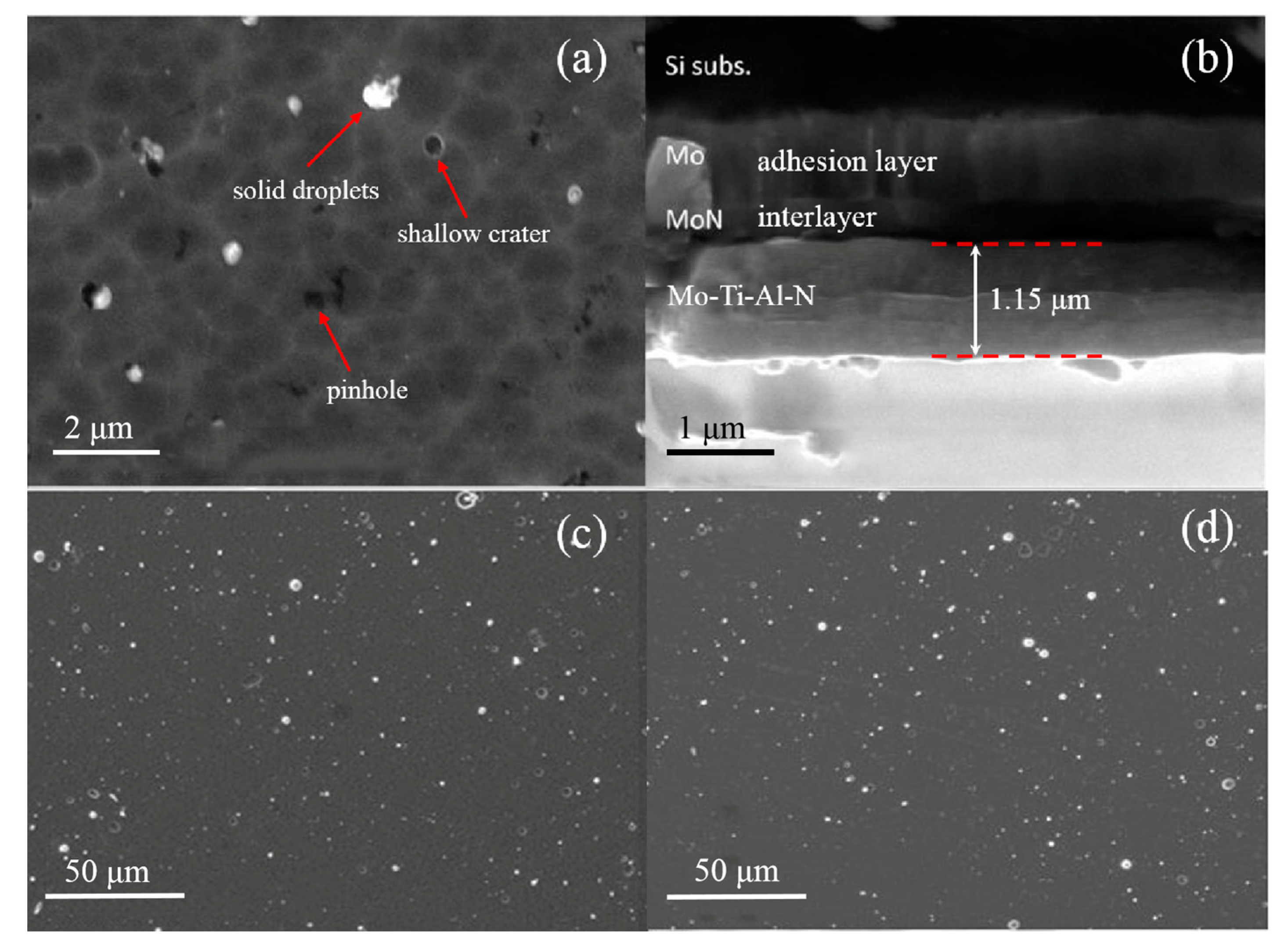
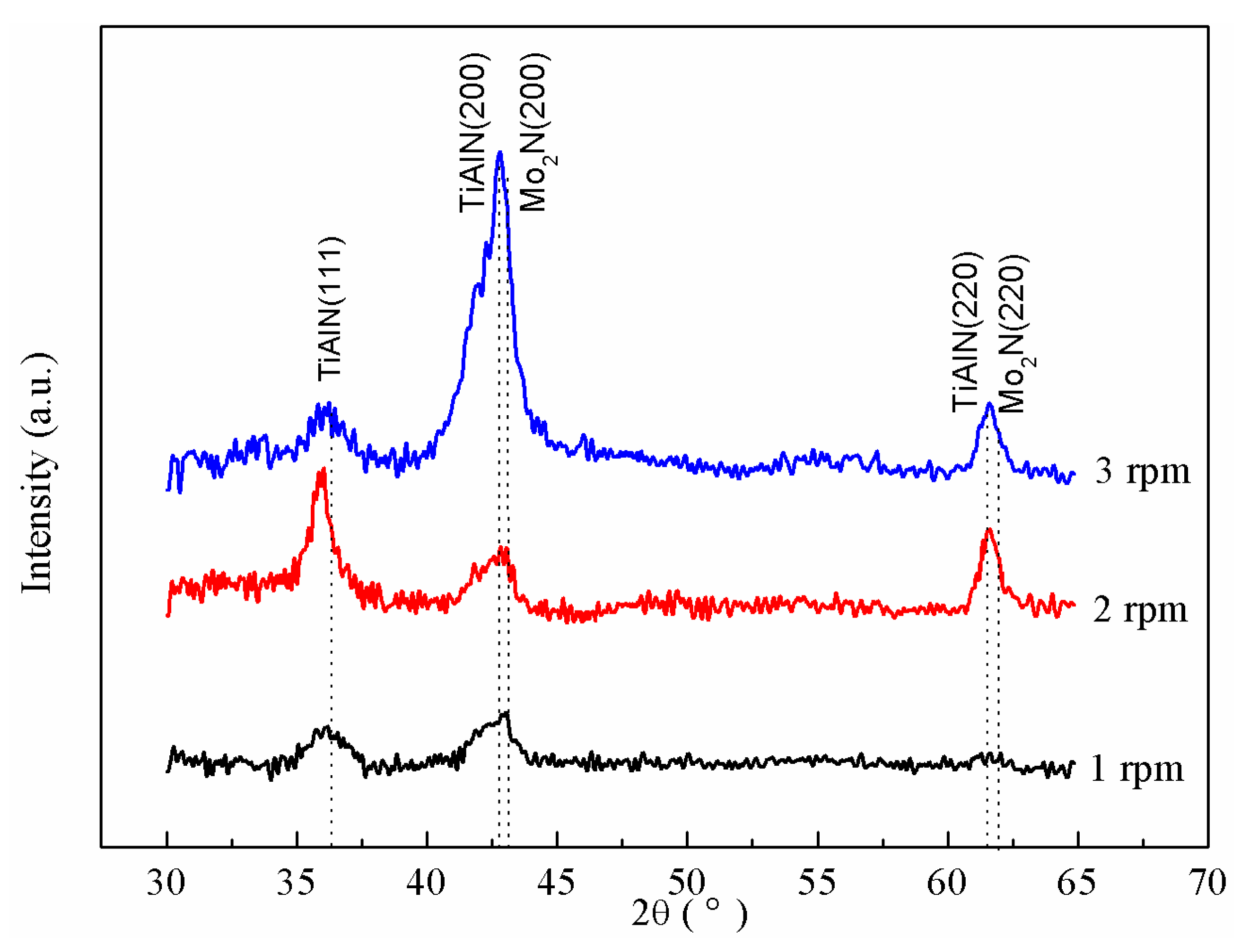
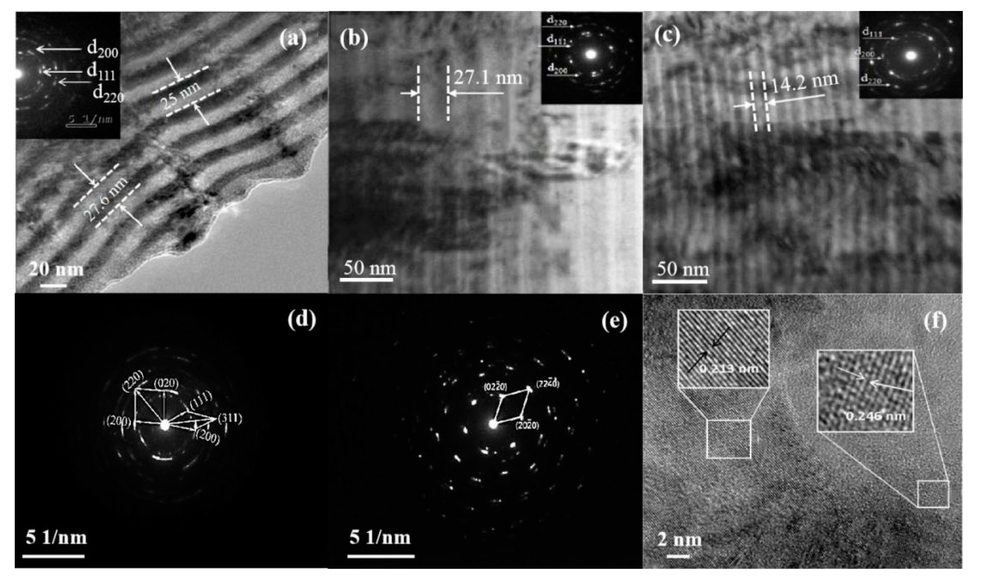
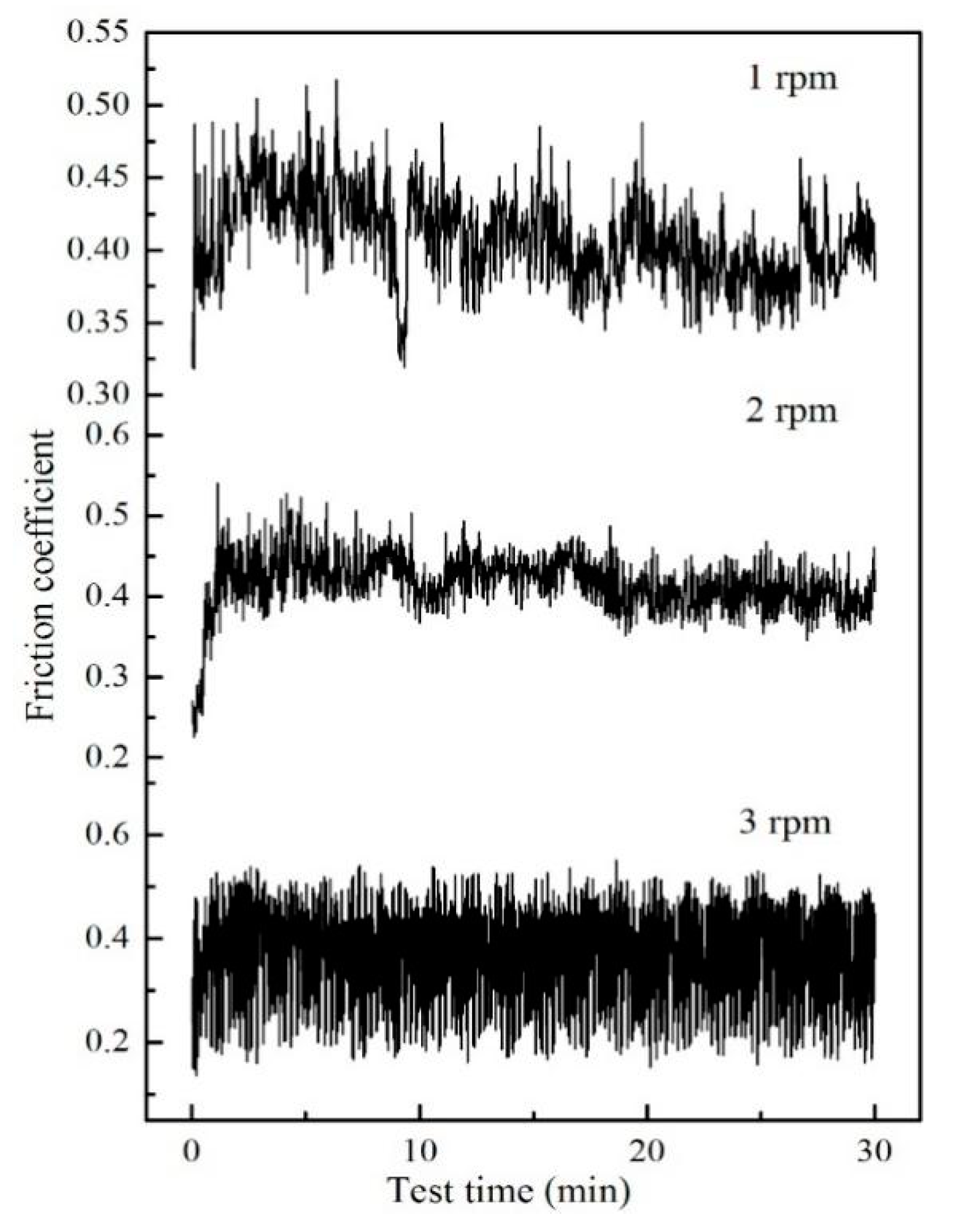
  • The deposited coatings represented TiAlN/Mo2N nanocomposite multilayered structures consisting of alternating cubic TiAlN and Mo2N phases with an average modulation period of 26 nm. Under low substrate rotation, their microhardness reached 30, and friction coefficient was as low as 0.4 that bears out hard-lubricant features of the coatings.
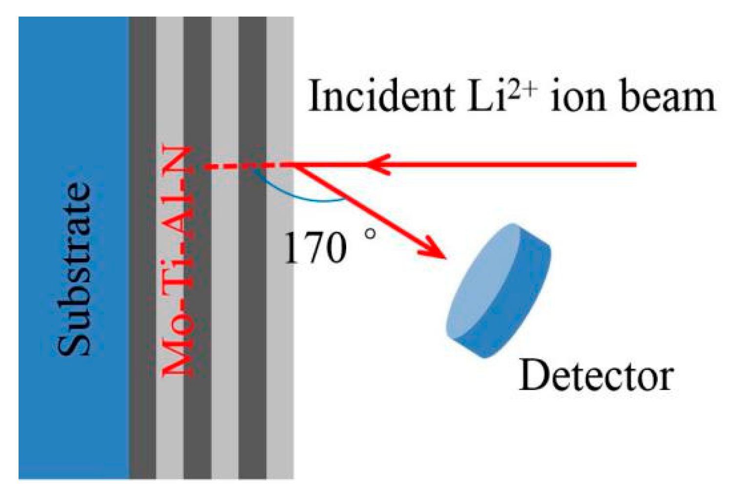
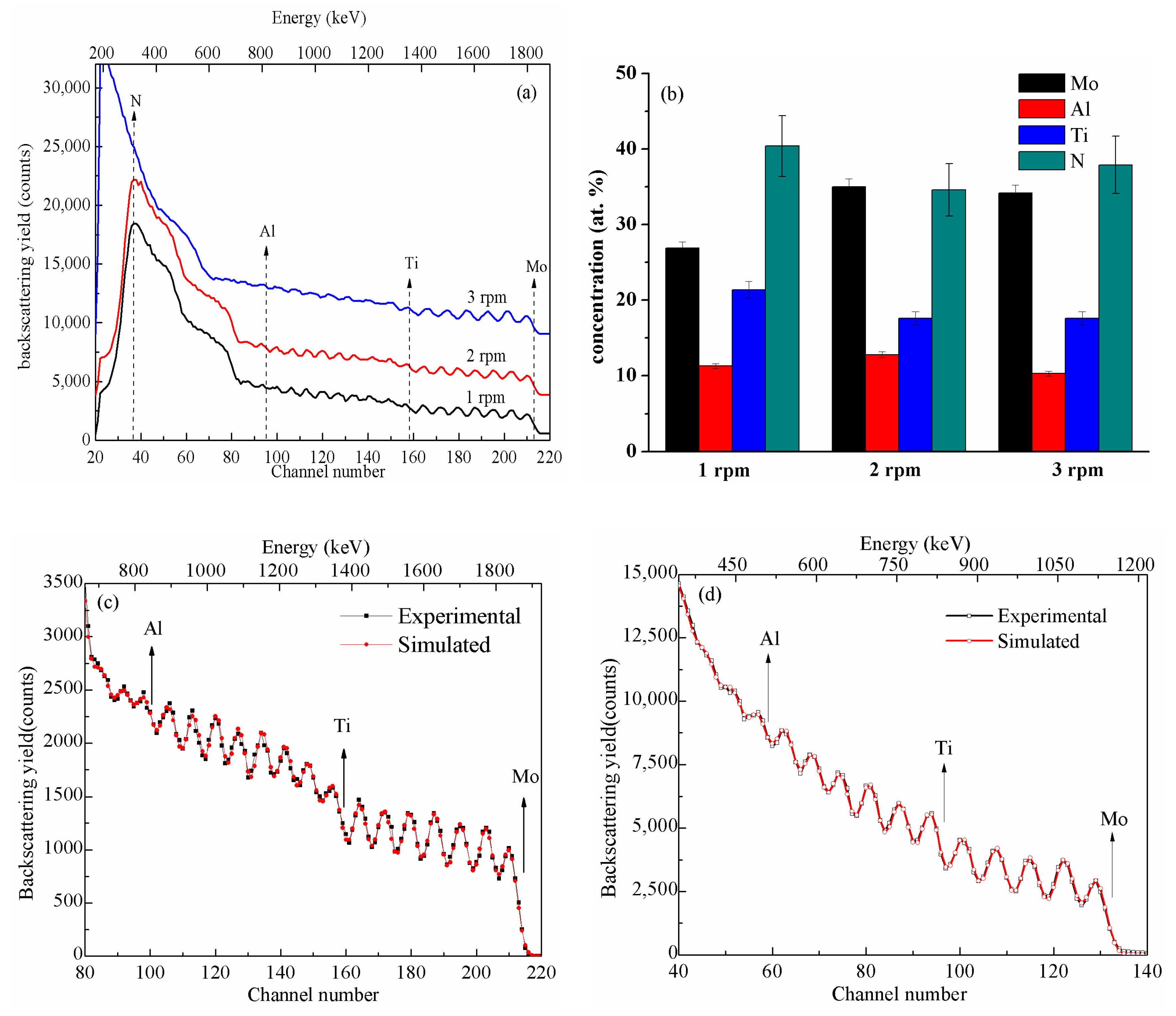
  • For Mo-Ti-Al-N multilayered coatings, RBS together with the SIMNRA code was used for evaluating the total atomic concentrations that can be figured out by EDS while the underdetermined N contents are almost equivalent at the corresponding substrate rotations. The Mo/(Ti + Al) ratio in the Mo0.269Ti0.214Al0.113N0.404 coatings at 1 rpm was lower than that of Mo0.350Ti0.176Al0.128N0.346 coatings at 2 rpm and Mo0.342Ti0.176Al0.103N0.379 coatings at 3 rpm, indicating that higher substrate rotation promoted an enrichment of Mo in the coatings dedicated to the reduction of friction coefficient.
  • RBS was also used for quantification of the individual bilayer of TiAlN/Mo2N multilayered coatings. When the initial energy of incident 7Li2+ ion beam reduced from 2.42 to 1.52 MeV, the estimated values of the modulation period were extrapolated to be 30.16 and 42.68 nm, respectively. Compared to HRTEM measurements, the main deviation possibly derived from the data processing of ideal structure model of the coatings. RBS as a non-destructive and quantitative ion-beam technique can provide a reliable and informative microstructural characterization of nanomultilayers.

Author Contributions

Conceptualization, Z.W., C.T., and D.F.; Investigation, Z.W., F.L., S.L., M.I.Y., and W.Z.; Visualization, V.P., A.T., D.H., and M.I.Y.; Formal analysis, D.H. and C.Z.; Writing—original draft preparation, Z.W. and C.T.; Writing—review and editing, A.T., S.I.G., and D.F.; Funding acquisition, C.T., F.L., C.Z., A.T., and D.F. All authors have read and agreed to the published version of the manuscript.

Funding

This research was funded by the Science and Technology Planning Project of Guangdong Province (No. 2018A050506082), the Ministry of Education and Science of the Russian Federation (No. 8.2810.2017), Natural Science Foundation of Guangdong Province (Nos. 2017A010103025 and 2018A030307027), Fundamental Research Project of Science, Technology and Innovation Commission of Shenzhen Municipality (No. JCYJ20180302153906051), Talent project (Nos. ZL1931 and ZL2047), and Scientific Research Grant (No. LZL1809) of Lingnan Normal University.

Conflicts of Interest

The authors declare no conflict of interest.

References

  1. Cselle, T.; Barimani, A. Today’s applications and future developments of coatings for drills and rotating cutting tools. Surf. Coat. Technol. 1995, 76, 712–718. [Google Scholar] [CrossRef]
  2. Starling, C.M.D.; Branco, J.R.T. Thermal fatigue of hot work tool steel with hard coatings. Thin Solid Films 1997, 308, 436–442. [Google Scholar] [CrossRef]
  3. Derflinger, V.; Brändle, H.; Zimmermann, H. New hard/lubricant coating for dry machining. Surf. Coat. Technol. 1999, 113, 286–292. [Google Scholar] [CrossRef]
  4. Kalss, W.; Reiter, A.; Derflinger, V.; Gey, C.; Endrino, J.L. Modern coatings in high performance cutting applications. Int. J. Refract. Met. Hard Mater. 2006, 24, 399–404. [Google Scholar] [CrossRef]
  5. Peter, I.; Rosso, M.; Gobber, F.S. Study of protective coatings for aluminum die casting molds. Appl. Surf. Sci. 2015, 358, 563–571. [Google Scholar] [CrossRef]
  6. Barnett, S.A.; Shinn, M. Plastic and elastic properties of compositionally modulated thin films. Annu. Rev. Mater. Sci. 1994, 24, 481–485. [Google Scholar] [CrossRef]
  7. Caiazzo, F.C.; Sisti, V.; Trasatti, S.P.; Trasatti, S. Electrochemical characterization of multilayer Cr/CrN-based coatings. Coatings 2014, 4, 508–526. [Google Scholar] [CrossRef] [Green Version]
  8. PalDey, S.; Deevi, S.C. Single layer and multilayer wear resistant coatings of (Ti, Al) N: A review. Mater. Sci. Eng. A 2003, 342, 58–79. [Google Scholar] [CrossRef]
  9. Qiu, Y.; Zhang, S.; Lee, J.W.; Li, B.; Wang, Y.X.; Zhao, D.L. Self-lubricating CrAlN/VN multilayer coatings at room temperature. Appl. Surf. Sci. 2013, 279, 189–196. [Google Scholar] [CrossRef]
  10. Gannon, P.E.; Tripp, C.T.; Knospe, A.K.; Ramana, C.V.; Deibert, M.; Smith, R.J.; Gorokhovsky, V.I.; Shutthanandan, V.; Gelles, D. High-temperature oxidation resistance and surface electrical conductivity of stainless steels with filtered arc Cr-Al-N multilayer and/or superlattice coatings. Surf. Coat. Technol. 2004, 188, 55–61. [Google Scholar] [CrossRef]
  11. Bardi, U.; Chenakin, S.P.; Ghezzi, F.; Giolli, C.; Goruppa, A.; Lavacchi, A.; Miorin, E.; Pagura, C.; Tolstogouzov, A. High-temperature oxidation of CrN/AlN multilayer coatings. Appl. Surf. Sci. 2005, 252, 1339–1349. [Google Scholar] [CrossRef]
  12. Yao, S.H.; Kao, W.H.; Su, Y.L.; Liu, T.H. Effect of periods on wear performance of TiN/AlN superlattice films. Mater. Sci. Eng. A 2005, 392, 380–385. [Google Scholar] [CrossRef]
  13. Chen, L.; Du, Y.; Yin, F.; Li, J. Mechanical properties of (Ti, Al) N monolayer and TiN/(Ti, Al) N multilayer coatings. Int. J. Refract. Met. Hard Mater. 2007, 25, 72–76. [Google Scholar] [CrossRef]
  14. Ehiasarian, A.P.; Hovsepian, P.E.; Hultman, L.; Helmersson, U. Comparison of microstructure and mechanical properties of chromium nitride-based coatings deposited by high power impulse magnetron sputtering and by the combined steered cathodic arc/unbalanced magnetron technique. Thin Solid Films 2004, 457, 270–277. [Google Scholar] [CrossRef]
  15. Ou, Y.X.; Lin, J.; Tong, S.; Sproul, W.D.; Lei, M.K. Structure, adhesion and corrosion behavior of CrN/TiN superlattice coatings deposited by the combined deep oscillation magnetron sputtering and pulsed dc magnetron sputtering. Surf. Coat. Technol. 2016, 293, 21–27. [Google Scholar] [CrossRef]
  16. Wang, Z.Y.; Liu, J.; Wang, L.; Li, X.M.; Ke, P.L.; Wang, A.Y. Dense and high-stability Ti2AlN MAX phase coatings prepared by the combined cathodic arc/sputter technique. Appl. Surf. Sci. 2017, 396, 1435–1442. [Google Scholar] [CrossRef]
  17. Peng, C.; Zhao, Y.H.; Jin, S.J.; Wang, J.R.; Liu, R.; Liu, H.; Shi, W.B.; Sharafadeen, K.K.; Ren, L.; Yu, B.H.; et al. Antibacterial TiCu/TiCuN multilayer films with good corrosion resistance deposited by axial magnetic field-enhanced arc ion plating. ACS Appl. Mater. Interfaces 2019, 11, 125–136. [Google Scholar] [CrossRef]
  18. Irudayaraj, A.A.; Kuppusami, P.; Thirumurugesan, R.; Mohandas, E.; Kalainathan, S.V.; Raghunathan, S. Influence of nitrogen flow rate on growth of TiAlN films prepared by DC magnetron sputtering. Surf. Eng. 2007, 23, 7–11. [Google Scholar] [CrossRef]
  19. Yi, P.Y.; Peng, L.F.; Huang, J.Q. Multilayered TiAlN films on Ti6Al4V alloy for biomedical applications by closed field unbalanced magnetron sputter ion plating process. Mater. Sci. Eng. C 2016, 59, 669–676. [Google Scholar] [CrossRef]
  20. Geng, Z.; Shi, G.L.; Shao, T.M.; Liu, Y.; Quan, D.L.; Reddyhoff, T. Tribological behavior of patterned TiAlN coatings at elevated temperatures. Surf. Coat. Technol. 2019, 364, 99–114. [Google Scholar] [CrossRef]
  21. Yousaf, M.I.; Pelenovich, V.O.; Yang, B.; Liu, C.S.; Fu, D.J. Effect of bilayer period on structural and mechanical properties of nanocomposite TiAlN/MoN multilayer films synthesized by cathodic arc ion-plating. Surf. Coat. Technol. 2015, 282, 94–102. [Google Scholar] [CrossRef]
  22. Tian, C.X.; Han, B.; Zou, C.W.; Xie, W.; Li, S.Q.; Liang, F.; Tang, S.X.; Wang, Z.S.; Pelenovich, V.O.; Zeng, X.M.; et al. Synthesis of monolayer MoNx and nanomultilayer CrN/Mo2N coatings using arc ion plating. Surf. Coat. Technol. 2019, 370, 125–129. [Google Scholar] [CrossRef]
  23. Gliewicz, A.; Warcholinski, B.; Murzynski, D. The properties of molybdenum nitride coatings obtained by cathodic arc evaporation. Surf. Coat. Technol. 2013, 236, 149–158. [Google Scholar] [CrossRef]
  24. Seibert, F.; Döbeli, M.; Fopp-Spori, D.M.; Glaentz, K.; Rudigier, H.; Schwarzer, N.; Widrig, B.; Ramm, J. Comparison of arc evaporated Mo-based coatings versus Cr1N1 and ta–C coatings by reciprocating wear test. Wear 2013, 298, 14–22. [Google Scholar] [CrossRef]
  25. Koshy, A.; Graham, M.E.; Marks, L.D. Synthesis and characterization of CrN/Mo2N multilayers and phases of molybdenum nitride. Surf. Coat. Technol. 2007, 202, 1123–1128. [Google Scholar] [CrossRef]
  26. Embury, J.D.; Hirth, J.P. On dislocation storage and the mechanical response of fine scale microstructures. Acta Metall. Mater. 1994, 42, 2051–2056. [Google Scholar] [CrossRef]
  27. Subedi, S.; Beyerlein, I.J.; LeSar, R.; Rollett, A.D. Strength of nanoscale metallic multilayers. Scripta Mater. 2018, 145, 132–136. [Google Scholar] [CrossRef]
  28. Pogrebnjak, A.; Smyrnova, K.; Bondar, O. Nanocomposite multilayer binary nitride coatings based on transition and refractory metals: structure and properties. Coatings 2019, 9, 155. [Google Scholar] [CrossRef] [Green Version]
  29. Chu, W.K.; Mayer, J.W.; Nicolet, M.-A. Backscattering Spectrometry; Academic Press: New York, NY, USA, 1978. [Google Scholar]
  30. Wang, Y.Q.; Michael, A.N. Handbook of Modern Ion Beam Materials Analysis, 2nd ed.; Materials Research Society Press: Warrendale, PA, USA, 2010. [Google Scholar]
  31. Hans, M.; to Baben, M.; Chen, Y.T.; Pradeep, K.G.; Holzapfel, D.M.; Primetzhofer, D.; Kurapov, D.; Ramm, J.; Arndt, M.; Rudigier, H.; et al. Substrate rotation-induced chemical modulation in Ti-Al-O-N coatings synthesized by cathodic arc in an industrial deposition plant. Surf. Coat. Technol. 2016, 305, 249–253. [Google Scholar] [CrossRef]
  32. Hans, M.; Schneider, J.M. On the chemical composition of TiAlN thin films-Comparison of ion beam analysis and laser-assisted atom probe tomography with varying laser pulse energy. Thin Solid Films 2019, 688, 137251. [Google Scholar] [CrossRef]
  33. Tavares, C.J.; Rebouta, L.; Alves, E.; Barradas, N.P.; Pacaud, J.; Riviere, J.P. Study of roughness in Ti0.4Al0.6N/Mo multilayer structures. Nucl. Instrum. Methods Phys. Res. Sect. B 2002, 188, 90–95. [Google Scholar] [CrossRef]
  34. Tavares, C.J.; Rebouta, L.; Riviere, J.P.; Girardeau, T.; Goudeau, P.; Alves, E.; Barradas, N.P. Atomic environment and interfacial structural order of TiAlN/Mo multilayers. Surf. Coat. Technol. 2004, 187, 393–398. [Google Scholar] [CrossRef] [Green Version]
  35. Kong, D.J.; Fu, G.Z.; Wang, J.C. Interfacial bonding mechanism and bonding strength of AlTiCrN coating by cathodic arc ion plating. Surf. Interface Anal. 2015, 47, 198–205. [Google Scholar] [CrossRef]
  36. Mayer, M. SIMNRA, a simulation program for the analysis of NRA, RBS and ERDA. In AIP Conference Proceedings; IOP Institute of Physics Publishing LTD: Bristol, UK, 1999; Volume 475, pp. 541–544. [Google Scholar]
  37. Kotai, E. Computer methods for analysis and simulation of RBS and ERDA spectra. Nucl. Instrum. Methods Phys. Res. Sect. B 1994, 85, 588–596. [Google Scholar] [CrossRef]
  38. Mayer, M. SIMNRA User’s Guide of SIMNRA Version 7.01; Max-Planck-Institut für Plasmaphysik: Garching bei München, Germany, 2017. [Google Scholar]
  39. Sarioglu, C.; Demirler, U.; Kazmanli, M.K.; Urgen, M. Measurement of residual stresses by X-ray diffraction techniques in MoN and Mo2N coatings deposited by arc PVD on high-speed steel substrate. Surf. Coat. Technol. 2005, 190, 238–243. [Google Scholar] [CrossRef]
  40. Abadias, G. Stress and preferred orientation in nitride-based PVD coatings. Surf. Coat. Technol. 2008, 202, 2223–2235. [Google Scholar] [CrossRef]
  41. Klug, H.P.; Alexander, L.E. X-Ray Diffraction Procedures: For Polycrystalline and Amorphous Materials, 2nd ed.; Wiley-VCH: Weinheim, Germany, 1974. [Google Scholar]
  42. Ihara, H.; Kimura, Y.; Senzaki, K.; Hirabayashi, M. Electronic structures of B1 MoN, fcc Mo2N, and hexagonal MoN. Phys. Rev. B 1985, 31, 3177–3178. [Google Scholar] [CrossRef]
  43. Fukumoto, N.; Ezura, H.; Yamamoto, K.; Hotta, A.; Suzuki, T. Effects of bilayer thickness and post-deposition annealing on the mechanical and structural properties of (Ti, Cr, Al) N/(Al, Si) N multilayer coatings. Surf. Coat. Technol. 2009, 203, 1343–1348. [Google Scholar] [CrossRef]
  44. Xu, Y.X.; Chen, L.; Pei, F.; Du, Y. Structure and thermal properties of TiAlN/CrN multilayered coatings with various modulation ratios. Surf. Coat. Technol. 2016, 304, 512–518. [Google Scholar] [CrossRef]
  45. Chowdhury, S.; Beake, B.D.; Yamamoto, K.; Bose, B.; Aguirre, M.; Fox-Rabinovich, G.S.; Veldhuis, S.C. Improvement of wear performance of nano-multilayer PVD coatings under dry hard end milling conditions based on their architectural development. Coatings 2018, 8, 59. [Google Scholar] [CrossRef] [Green Version]
  46. Zhou, S.Y.; Pelenovich, V.O.; Han, B.; Yousaf, M.I.; Yan, S.J.; Tian, C.X.; Fu, D.J. Effects of modulation period on microstructure, mechanical properties of TiBN/TiN nanomultilayered films deposited by multi arc ion plating. Vacuum 2016, 126, 34–40. [Google Scholar] [CrossRef]
  47. Fu, T.; Zhang, Z.J.; Peng, X.H.; Weng, S.Y.; Miao, Y.H.; Zhao, Y.B.; Fu, S.Y.; Hu, N. Effects of modulation periods on mechanical properties of V/VN nano-multilayers. Ceram. Int. 2019, 45, 10295–10303. [Google Scholar] [CrossRef]
  48. Chu, X.; Barnett, S.A.; Wong, M.S.; Sproul, W.D. Reactive unbalanced magnetron sputter deposition of polycrystalline TiN/NbN superlattice coatings. Surf. Coat. Technol. 1993, 57, 13–18. [Google Scholar] [CrossRef]
  49. Wu, W.W.; Chen, W.L.; Yang, S.B.; Lin, Y.; Zhang, S.H.; Cho, T.-Y.; Lee, G.H.; Kwon, S.-K. Design of AlCrSiN multilayers and nanocomposite coating for HSS cutting tools. Appl. Surf. Sci. 2015, 351, 803–810. [Google Scholar] [CrossRef]
  50. Svahn, F.; Kassman-Rudolphi, Å.; Wallen, E. The influence of surface roughness on friction and wear of machine element coatings. Wear 2003, 254, 1092–1098. [Google Scholar] [CrossRef]
  51. Harlin, P.; Carlsson, P.; Bexell, U.; Olsson, M. Influence of surface roughness of PVD coatings on tribological performance in sliding contacts. Surf. Coat. Technol. 2006, 201, 4253–4259. [Google Scholar] [CrossRef]
  52. To Baben, M.; Raumann, L.; Music, D.; Schneider, J.M. Origin of the nitrogen over- and understoichiometry in Ti0.5Al0.5N thin films. J. Phys. Condens. Matter 2012, 24, 155401. [Google Scholar] [CrossRef]
  53. To Baben, M.; Hans, M.; Primetzhofer, D.; Evertz, S.; Ruess, H. Unprecedented thermal stability of inherently metastable titanium aluminum nitride by point defect engineering. Mater. Res. Lett. 2017, 5, 158–169. [Google Scholar] [CrossRef]
Figure 1. Experimental set-up (top view) for deposition of Mo-Ti-Al-N composite coatings, not to scale.
Coatings 10 00101 g001
Figure 2. Geometrical schematic of RBS experiments.
Coatings 10 00101 g002
Figure 3. SEM images of Mo-Ti-Al-N composite coatings fabricated: surface morphological (a) and cross-sectional (b) images at 2 rpm; surface morphological images (c) at 1 rpm and (d) at 3 rpm.
Coatings 10 00101 g003
Figure 4. XRD patterns of Mo-Ti-Al-N composite coatings fabricated at 1, 2, and 3 rpm.
Coatings 10 00101 g004
Figure 5. Cross-sectional bright-field HRTEM micrographs of Mo-Ti-Al-N composite coatings: fabricated at 2 rpm with (a) high magnification, (b) low magnification and fabricated at 3 rpm with (c) low magnification, where the upper insets are SAED patterns; SAED patterns of (d) B1 TiAlN and (e) hcp-MoN; (f) higher magnification for 2 rpm sample.
Coatings 10 00101 g005
Figure 6. Nanohardness and Young’s modulus versus the displacement for Mo-Ti-Al-N coatings fabricated at different rotating speeds: 1 rpm (a), 2 rpm (b), and 3 rpm (c). In panel (d), the mean values of both factors are shown versus the rotating speeds.
Coatings 10 00101 g006
Figure 7. Time dependencies of the friction coefficient of Mo-Ti-Al-N coatings fabricated at 1, 2, and 3 rpm.
Coatings 10 00101 g007
Figure 8. (a) RBS spectra using an incident 7Li2+ion beam of 2.42 MeV and (b) corresponding atomic concentrations of Mo-Ti-Al-N coatings fabricated at 1, 2, and 3 rpm; Experimental and simulated RBS spectra of the coatings at 2 rpm with black solid dots and red lines showing experimental data and SIMNRA6.05 simulation results, respectively when the initial energy of incident 7Li2+ ion beam is (c) 2.42 MeV and (d) 1.52 MeV.
Coatings 10 00101 g008
Table 1. Deposition parameters of Mo-Ti-Al-N composite coatings.
Deposition ParametersValue
Base pressure<2 × 10⁻³ Pa
Cathode targets Mo and Ti-Al (Ti 70 at.%)
Ar+ plasma cleaning−800 V substrate bias voltage with 80%
duty cycle for 20 min
Reactive gas flux and pressure N2, 40 sccm, 2.5 Pa
Cathodic arc current80 A for Mo target and 60 A for Ti-Al target
Substrate bias voltage and
temperature
−200 V and 300 ℃
Rotating speed of sample bracket1, 2, 3 rpm
Deposition time of Mo-Ti-Al-N 20 min
Mo and MoN interlayersMo target arc current 70 A, bias voltage −200 V, working pressure 0.5 Pa, deposition time 18 min
Table 2. Chemical composition, hardness, and friction coefficient of Mo-Ti-Al-N coatings prepared at various substrate rotation rates
Substrate Rotation RateChemical Composition (at.%)Nano-
Hardness
(GPa)
Young’s Modulus
(GPa)
Mean Friction Coefficient
Mo LTi KAl KN K
1 rpm33.2522.189.8434.7328 ± 2475 ± 200.407
2 rpm35.7623.1710.1330.9432 ± 1500 ± 300.415
3 rpm35.0722.729.9632.2535 ± 2600 ± 500.387

