Review

Percolation Model for Renewable-Carbon Doped Functional Composites in Packaging Application: A Brief Review

1
Center for Biocomposites and Biomaterials Processing, Department of Mechanical and Industrial Engineering, University of Toronto, 33 Willcocks St., Toronto, ON M5S 3B3, Canada
2
Key Laboratory of Food Nutrition and Safety (Tianjin University of Science and Technology), Ministry of Education, Tianjin 300457, China
3
Department of Chemical Engineering, University of New Brunswick, Fredericton, NB E3B 5A3, Canada
4
Key Laboratory of Pulp & Paper Science and Technology of Shandong Province, Ministry of Education, Qilu University of Technology (Shandong Academy of Sciences), Jinan 250353, China
*
Author to whom correspondence should be addressed.
Coatings 2020, 10(2), 193; https://doi.org/10.3390/coatings10020193
Submission received: 23 January 2020 / Revised: 18 February 2020 / Accepted: 21 February 2020 / Published: 24 February 2020
(This article belongs to the Special Issue Bio-Based Active Packaging for Shelf Life Extension)

Abstract

:
This review summarizes the application of percolation theory for the behavior simulation of renewable-carbon in its doped packaging composites. Such dopant-reinforced materials have sparked considerable interest due to the significant improvement on the aesthetic and mechanical properties at considerable low filler content (<1% in some cases), which would further boost their potential use in the food and pharmaceutical packaging industries. We focused mainly on the percolation behavior, which is closely related to the distribution of renewable carbon particles in the presence of polymeric matrix. The effect of geometry, alignment and surface property is of particular relevance to the percolation threshold of composites containing carbon fillers. Validity, as well as limitations of the mostly used percolation models, is further discussed. Finally, despite its recent emergence as functional filler, carbon-based nanocellulose has been extensively developed for a wide range of applications. This inspired the concept to use nanocellulose as a secondary bio-additive for packaging purposes, such as functional nanocellulose-coated film where primarily synthetic polymers are used. The microstructure and functionality of rod-like nanocellulose in its use for film composite are specifically discussed.

1. Introduction

Increasing environmental concern has led to the rapid growth of bio-based materials as alternatives to petroleum-based derivatives [1]. Renewable carbon, a burgeoning material derived from biomass sources, possesses abundant functionalizable groups with ultra-low density. Its exceptional mechanical properties and surface reactivity make this new form of carbon an excellent candidate for packaging-composite reinforcement [2].
Typically, enhanced aesthetics of packaging material can be achieved via the embedding of reinforced additives, such as carbon black, silver nanoparticles or nano-titanium [3,4,5,6], which are majorly derived from nonrenewable sources. Though these functional reinforcement agents offer a great number of benefits to the finished parts, designing biobased additives is still of importance [7], especially for the food and pharmaceutical industries, which having high safety concerns. Biobased nanofillers, such as hairy cellulose and renewable carbon, possess many of the same advantages as regular fillers but come from plant-derived sources and can be potentially synthesized to become compatible with the polymeric matrix as for packaging use [8,9]. For instance, many studies regarding the polymer blends have shown that renewable carbon can generate higher surface gloss at its lower dosage, due to the ability to reside in either the minor or major phase, or the interfacial region inside of the polymeric blends.
In addition to its contribution to the aesthetics, renewable carbon can further enhance the mechanical properties, while reducing the product weight, which is critical for packaging industries. However, it is not without challenge. Notably, the overdosed renewable carbon would generate negative effects on the tensile/impact strength. The processing cost would be increased as well. It is thus crucial to manipulate the concentration of renewable carbon in order to cover the aforementioned disadvantages. However, comparatively little progress has been reported in regard to using the conventional optimization methods, due to their limitations in dealing with the unusual properties of renewable carbon, such as its complex geometry and unique porous structure. Percolation model, which is established for quantifying the dosage of additive inside of its doped composite, can be used to study the mobility dynamics of renewable carbon in a specific and systematic manner. The concentration and localization of renewable carbon in its doped composite can be manipulated to improve the overall performance of the finished products.

2. Renewable Carbon/Carbon Complex

Renewable carbon is one of the most important materials which have been used in a wide range of applications, such as chemical catalysis, medicinal purification, environmental cleaning and metal extraction [10]. Meanwhile, with the development of technology, the use field of renewable carbon keeps expanding to new areas, such as electrode and super-capacitors for energetic cell, as well as many other innovative industries. Similar to carbon nanotube (CNT) or graphene, it has variable characteristics of surface groups, along with high interface reactivity [11]. These surface groups provide abundant reaction sites for chemical modification via electrostatic/van der Waals force, chemical bonding or noncovalent π-π interactions (Figure 1), thus imparting carbon particles with excellent natural affinity toward a large number of substrates [12]. Moreover, the highly developed porous structure renders renewable carbon with a large range of surface area (500–3000 m2/g). It consists of thin graphite layers with exceptional mechanical strength, which highlights its great potential to be used as reinforcement agent in advanced packaging composites.
The production of renewable carbon involves two steps: carbonization and activation. The carbonization process can create the initial porosity and enrich the carbon content, while activation, the second step, is capable to enhance the pore structure. As for its raw materials, a large number of botanical origins, such as wood, bamboo or coconut shells, can be potentially selected for the physical (gaseous carbon dioxide or steam) or chemical (strong chemicals such as alkali-metal hydroxides) reaction. Particularly, agricultural by-products, a low-cost resource, can be considered since they are ultra-renewable, and the use of them may provide additional benefits of eliminating the environmental waste.

2.1. Classification of Renewable Carbon

Renewable carbon is a complex product, and this makes its classification difficult. Many different ways have been reported by considering the various features of renewable carbon, such as surface characteristics, reactivity and physical behaviors [13]. Based on the geometry, renewable carbon can be classified into granular renewable carbon and powdered renewable carbon, and each type has its own application area, such as gas adsorbent (granular renewable carbon) and water cleaning (powdered renewable carbon).

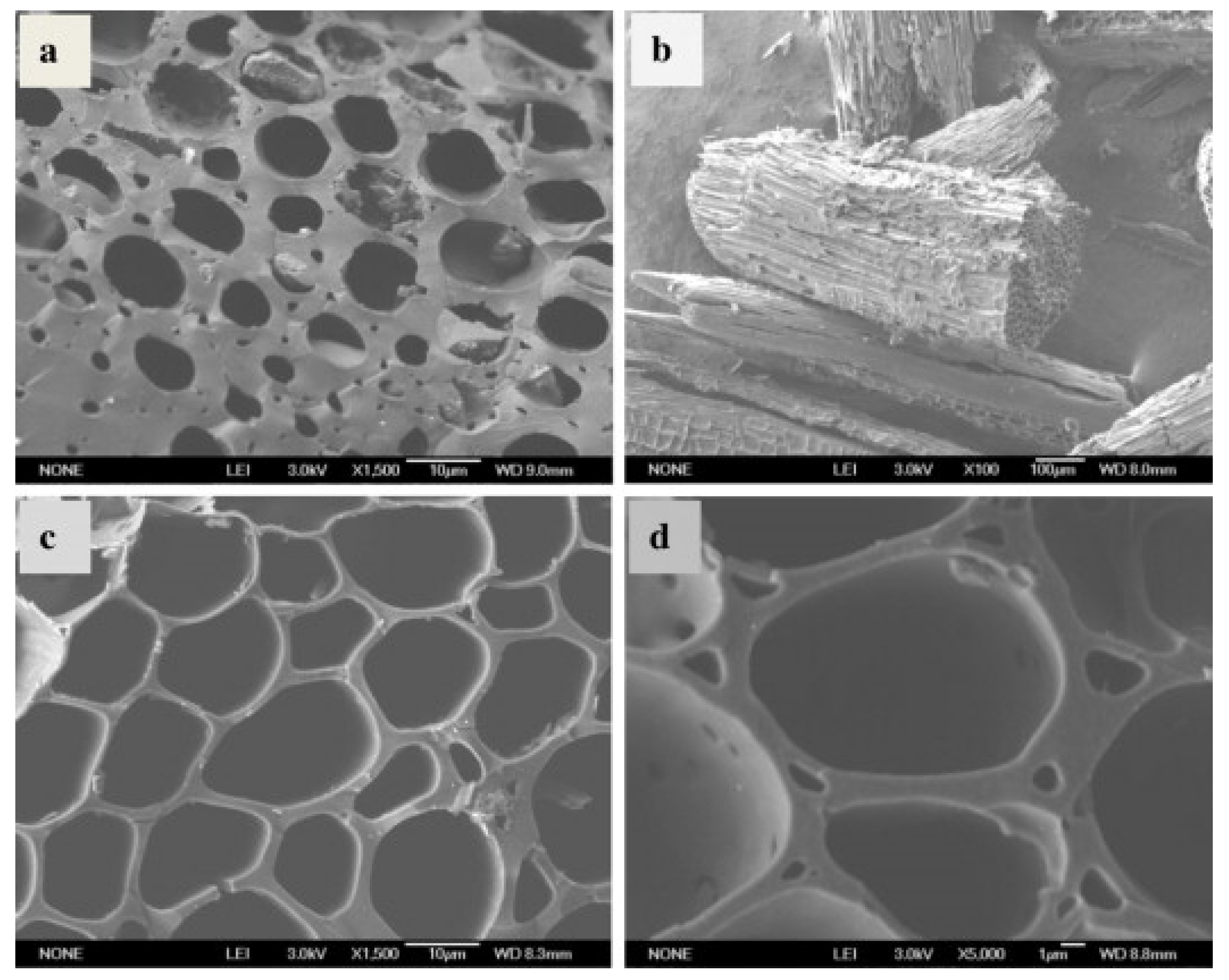
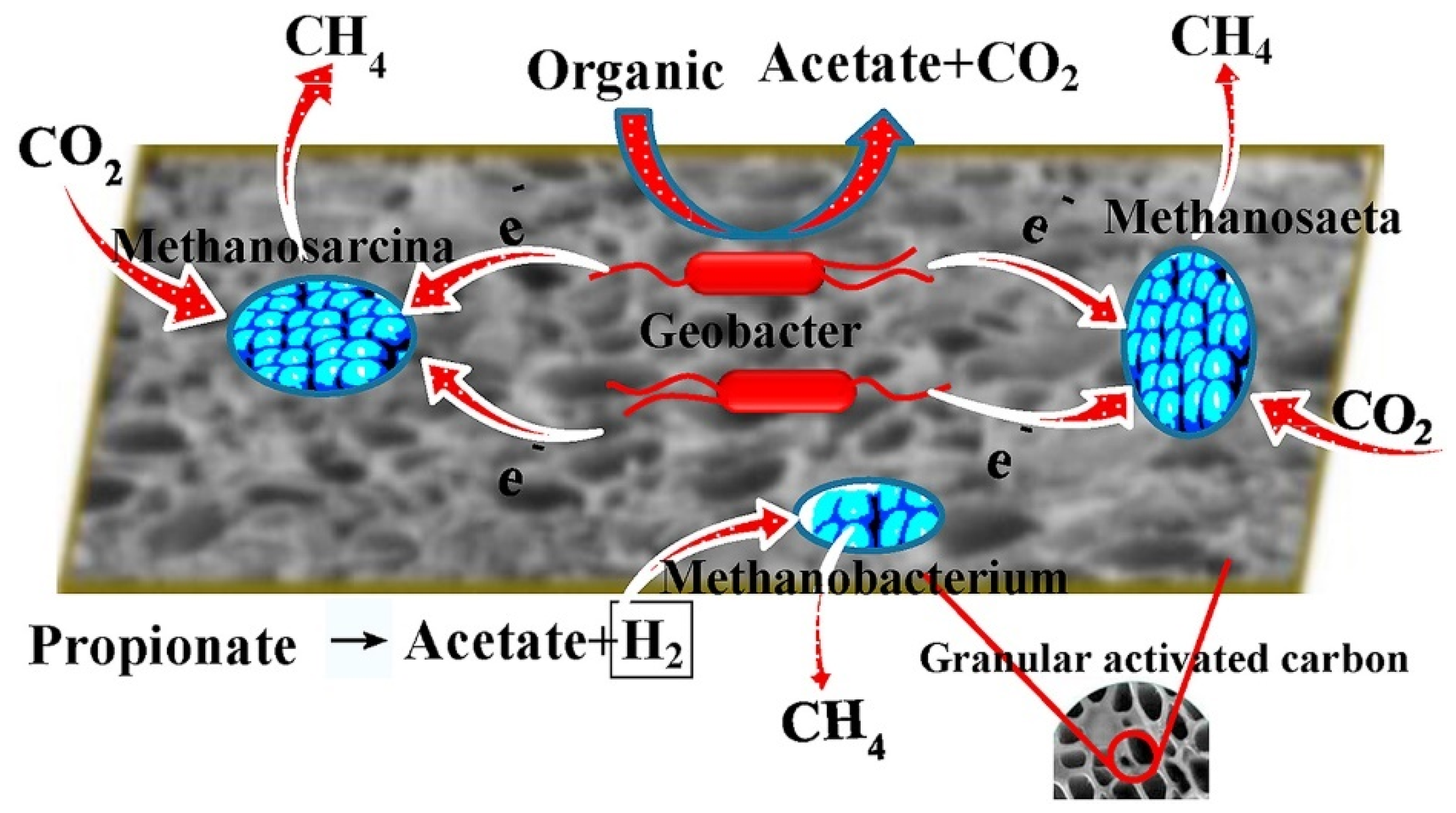
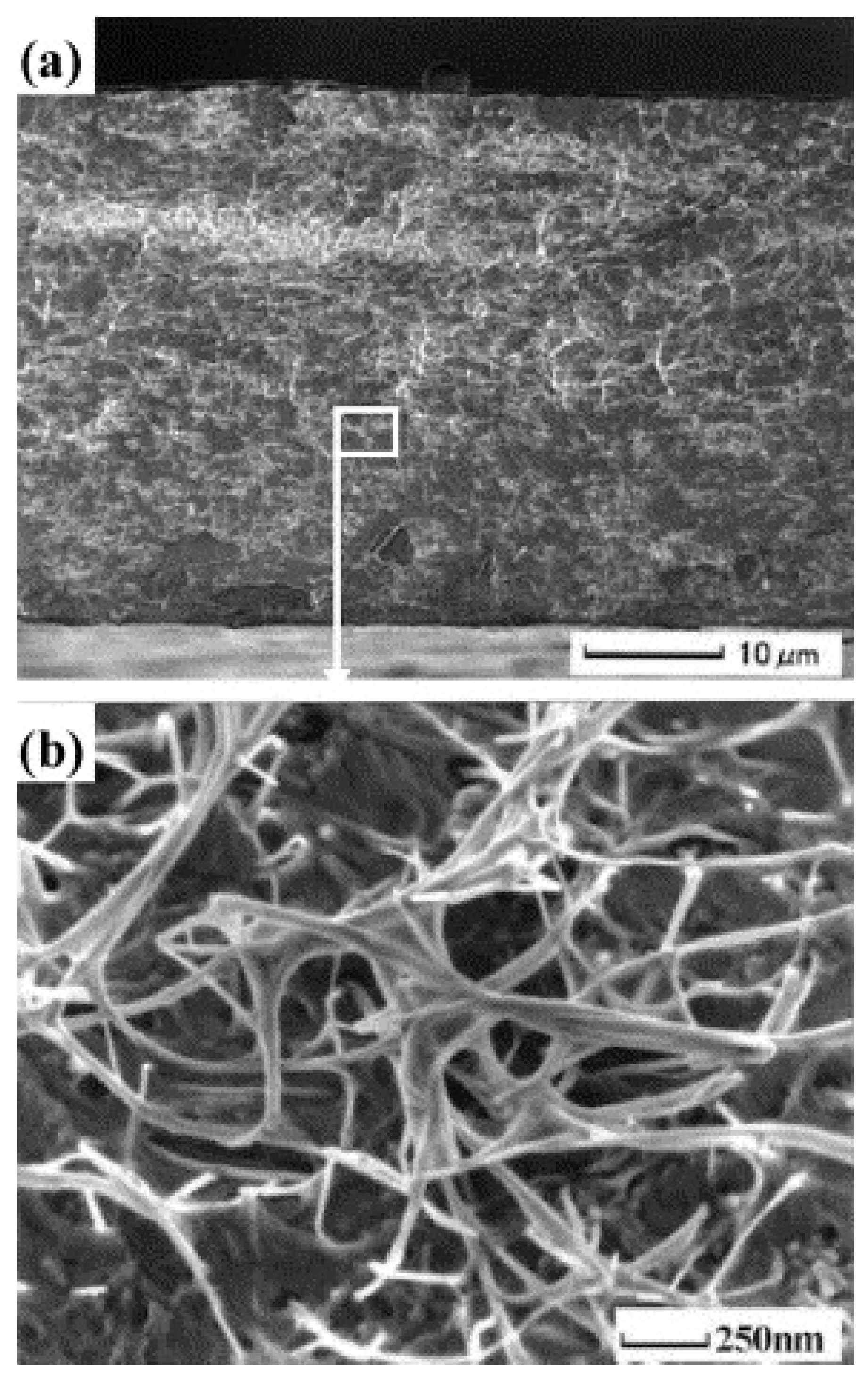
2.1.1. Granular Renewable Carbon

Granular renewable carbon has been widely used as a functional adsorbent for a wide range of applications. The particle size of granular carbon is relatively larger, thus with smaller specific surface area. Figure 2 shows the bamboo-derived granular renewable carbon prepared via KOH activation. Large pores can be observed from the scanning electron microscopy images (SEM, JSM-6460LV, JEOL) [14].
As for the application, granular renewable carbon can be employed for gas purification or for the separation of components in flow systems, due to its high diffusion rate [15]. Yang et al. used granular carbon to accelerate the syntrophic metabolism of a batch-mode anaerobic sludge treatment, via enhancing the electron exchange between syntrophs and methanogens (Figure 3). An increase of 17.4% for the methane production was achieved, as the dosage of granular carbon increased from 0 to 5.0 g [16].

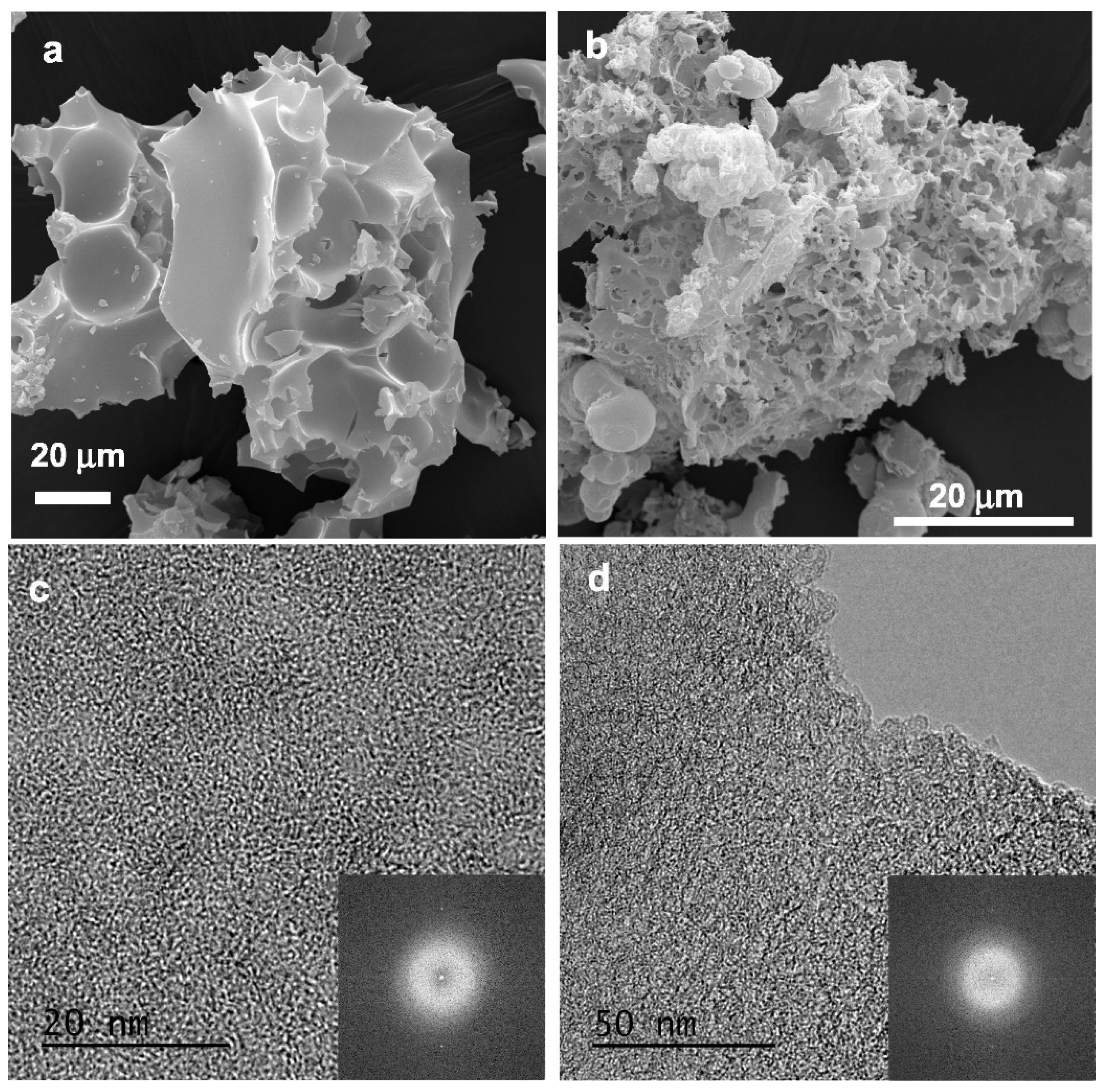
2.1.2. Powdered Renewable Carbon

Renewable carbon in its particular powder form is generally with larger internal surface. It has an average diameter between 0.1 and 25 mm, with a length of less than 100 mm. Figure 4 shows the microstructure of a typical powdered carbon with large conchoidal cavities and smooth surfaces (Figure 4a,b) [17]. Its porosity is made up of randomly distributed pores, as displayed in Figure 4c,d. The inset Fast Fourier Transform (FFT) pattern further confirms the amorphous structure of generated powder carbon. The high surface area, as well as the small diffusion distance, allows the carbon powder to be directly used in the process units.
Recently, a new type of superfine powdered renewable carbon has been emerging as an effective adsorbent material with a size of 0.1–1 μm, which is an order of magnitude smaller than the conventional powdered carbon. Partlan et al. prepared the superfine powdered carbon from both wood and coconut-shell sources [18]. A wet mill with yttrium-stabilized zirconium oxide beads (dimension of 0.3–0.5 mm) was used to grind the raw materials into different sizes by controlling the milling time. The results revealed that both wood-based and coconut-shell-based carbons had their particle size decreased at a longer milling time. However, the specific surface area and pore volume distributions remained independent of the milling time. Comparing with regular powdered renewable carbon, superfine carbon showed an increased adsorption capacity for contaminants in the drinking water.
Besides the aforementioned two types of carbon, impregnated renewable carbon and extruded renewable carbon are also popular in the market. As for their application, the former can be used for air-pollution control [19], while the latter is suitable for gas-phase applications [20].

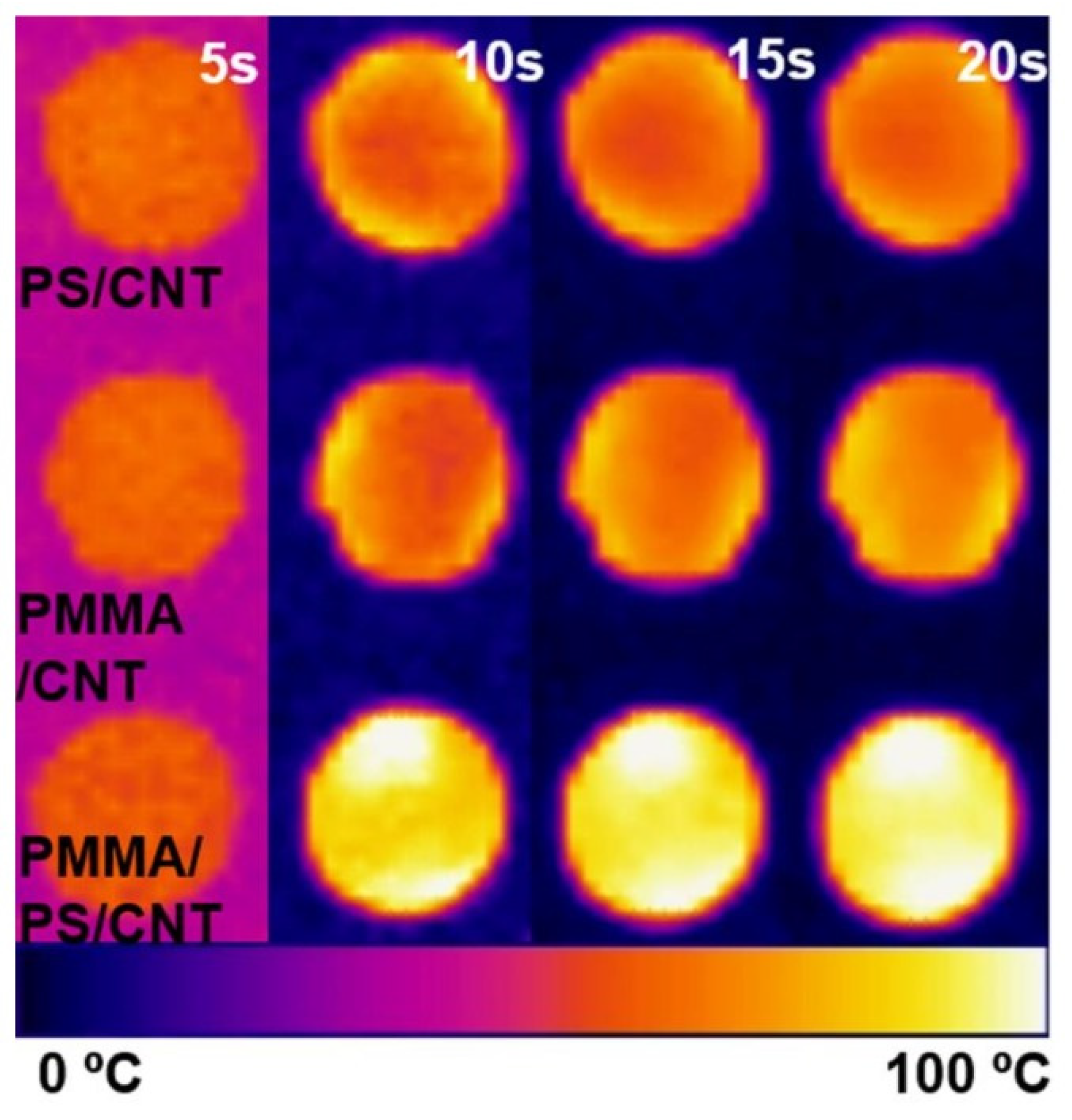
2.2. Use of Renewable Carbon in the Reinforced Packaging Polymeric Composites

Renewable carbon has been widely used to modify the mechanical strength of polymeric composites [21]. Typically, its rod-like shape in the form of CNT/graphene has an abundance of unique properties (Figure 5), such as high strength/stiffness, excellent energy transfer/absorbing, controllable conductivity and good dispersion in the multifunctional composites, as well as being lightweight [12].
Many studies have been reported, each with a different focus, on the structural properties of renewable carbon doped polymeric composites [22,23]. Shown in Figure 6 is a typical example of incorporating biocarbon into poly(hydroxybutyrate-co-hydroxyvalerate) (PHBV)/poly(lactic acid) (PLA) blends to enhance their mechanical functions [24]. However, the potential deleterious reaction of biocarbon with polymers might negatively affect the morphology and melt dynamic of the finished products. Phase separation method was therefore suggested as a possible solution, to improve the overall properties, while reducing the percolation threshold of carbon fillers. This was in agreement with a later work conducted by Meincke et al. [25], whose initial study was to evaluate the rheological properties and mechanical strength of CNT doped polyamide-6. Measurements of the viscous behavior suggested that the carbon in its form of nanotubes showed a percolation threshold of 2–4 wt%, which was mainly attributed to a dual percolation effect: CNT percolated inside of the polyamiode-6 phase (first percolation), which itself percolated within the blend matrix (second percolation). Rheological experiments showed that, at threshold, the material exhibited a fluid–solid transition in the molten state. The notched impact strength decreased as the increasing of filler content. However, the toughness of blends was still higher than the ones doped with carbon black.
Moreover, it was reported that renewable carbon can selectively disperse into one of the two polymers or their interface, due to the different affinity between renewable carbon and polymer. The overall distribution of renewable carbon fillers in the blends is governed by the percolation of carbon-rich phase and the continuity of this phase in the finished product. Certain chemical modifications are favorable for the localization of renewable carbon, e.g., Gubbels et al. reported a thermodynamic method to selectively localize carbon at the interface of a binary polymer via the surface oxidation of carbon [26]. The introduction of a copolymer, which has higher affinity to renewable carbon, can also be considered to be a feasible approach to favor the accumulation of renewable carbon at the interface. In another study, Wu et al. defined two key parameters, critical matrix ligament thickness (τc) and inter-particle distance (τ) [27], to simulate the mechanical behavior of the composites. Moreover, τc represents the thickness at which the matrix ductility can be improved drastically, and the expression of τ can be written as Equation (1):
τ = d · [ ( π 6 V f ) 1 3 1 ]
where d stands for the particle diameter.
The results indicated that the shear yielded zones throughout polymer matrix would result in a brittle–tough transition. In the case of τ < τc, a remarkable increase of the toughness is perceivable. Therefore, the smaller the filler, the lower the concentration it would require to realize the brittle-tough transition under sufficient interfacial adhesion. Percolation mechanism was concluded as the leading attribution for the improved strength and toughness as the filler loading increased at τ < τc.

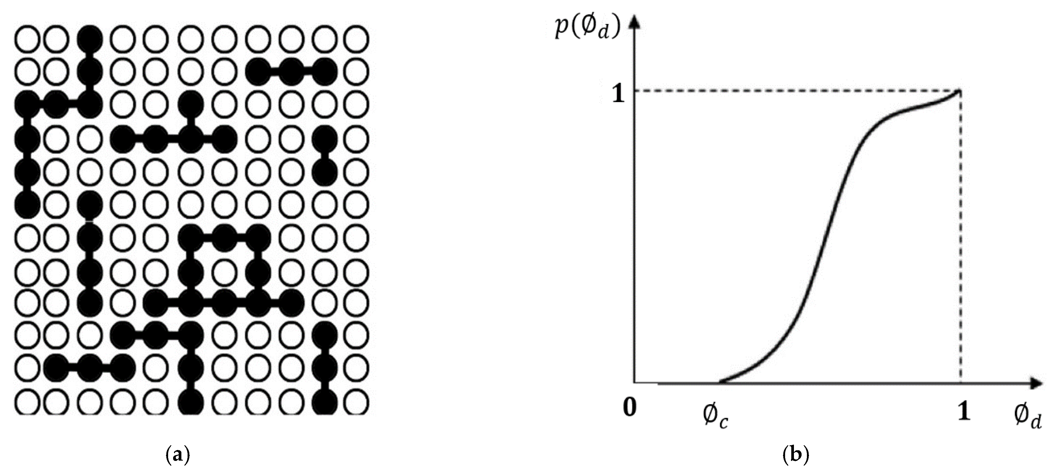
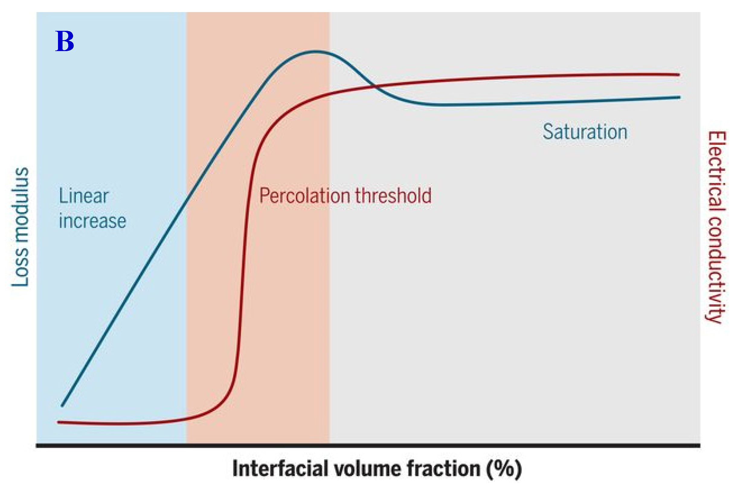
3. Percolation Theory

Percolation theory is served as universality class in critical phenomena characterized by a set of exponents regarding their scaling structure of the corresponding geometric features [28]. It has been applied in a large variety of technological and engineering processes. Various transition phenomena, such as virus propagation or sol–gel transition, can be described by percolation theory [29,30]. Since the early 1980s, extensive analytical and computational studies of percolation behavior have been conducted for fillers-reinforced polymeric composites, with the aim to enhance the performance [31].
Technically, the fillers-doped composites can be simplified into two phases: dispersed phase (fillers or additives) and continuous phase (polymer). In the simulated system, the geometry of the dispersed phase is normalized, and its microstructure is considered to be dimensionless. The whole composite can be thus modeled into an infinite lattice (Figure 7a), where the sites are connected by continuous phase, except for the ones which are occupied by dispersed phase [32]. The probability of these connections, also named as percolation probability p(ϕd), can be increased as the site occupation rising (ϕd). The minimum rate of site occupation for percolation is described as percolation threshold (ϕc), which is the critical filler volume fraction needed to obtain an initial percolating path throughout the matrix. As shown in Figure 7b, there is no percolation at ϕd < ϕc, which means the percolation probability is 0. Meanwhile, at the ϕdϕc, the percolation probability gradually increases toward 1.
Mechanical and surface aesthetics properties are highly dependent on the percolation dynamic of fillers. In general, renewable carbon with homogeneous structure, such as branched primary aggregates and low chemisorbed oxygen complexes, can decrease the percolation threshold in its composites. On the other hand, the heterogeneous structure mostly requires a larger concentration of renewable carbon to generate its percolation networks. The high dose of this kind of bio-particle would usually have a negative effect on the mechanical properties and processability. Moreover, the sloughing of renewable carbon would be more severe under its high concentration.
In the percolating system, the fillers doped into the polymeric matrix can also be classified into two types of clusters: the finite clusters and the percolating clusters (infinite clusters), comprising a backbone and dangling bonds (Figure 8a) [29]. Around the percolation threshold, the mechanical properties are closely related to the weight P of infinite clusters, as shown in Equation (2):
P ( ) = A ( c ) β
where ϕ is the volume fraction of fillers, A is a dimensionless constant, ϕc is the critical volume fraction and β is a critical exponent which solely related to the system dimension (β is 0.4 for 3D-system).
It was demonstrated that both finite and infinite (backbone and dangling bonds) clusters were capable of affecting the mechanical strength, to various extents. In general, the infinite cluster has the most reinforcing effect, the finite cluster has the lowest and the dangling bonds lie in between. Shown in Figure 8b is an established model with springs in series and parallel, to describe the percolation behavior of fillers toward the mechanical stress. Fillers in finite clusters are associated with series, considering their lower contribution to the reinforcement, and in parallel stand for the fillers in infinite. For ϕ < ϕc, the volume fraction of the infinite cluster ϕ is zero. For ϕϕc, ϕ can be defined by using Equation (3). The critical exponent b lies between 0.4 and 1.6. The lower the value of b is, the stronger the interaction between fillers and polymeric matrix will be. If b = 0.4, the reinforcing effect of the dangling bonds is similar as backbone. While b = 1.6 means no reinforcement from dandling bonds. Accordingly, the elastic modulus, Ecomposite, of the composite can be expressed as Equation (4), in which, Efiller-filler represents the stiffness of the filler–filler clusters. It highly depends on the intrinsic stiffness of filler itself, plus the binding stiffness between fillers. In the literature, the filler–filler stiffness for polymeric composites was usually set at 2.0 or 1.8 GPa [33].
= ( c 1 c ) b
E composite = ( 1 2 + ) E filler filler E polymer + ( 1 ) E filler filler 2 E polymer ( ) + E filler filler ( 1 )

4. The Effect of Renewable Carbon Characteristics on Its Percolation Behavior

Nowadays, the renewable-carbon-doped composite is witnessing its significant development for packaging applications because of the environmental advantage over many other types of fillers, such as carbon black and metal fibers. Exploiting the full potential of this newly emerged material requires a comprehensive understanding and predictive capability of its property–function relationships. This is particularly necessary for simulating the geometric percolation dynamics.
Renewable carbon prepared from different methods is usually with varying size and surface morphology. These factors are believed to be the main reason for the considerable disparity in thresholds and mechanical properties among the prepared polymeric composites. It is therefore critical to address the effect of filler characteristics on its percolation mechanism. In general, the preferred renewable carbon is with high surface area (small particles size), optimal structure (branched primary aggregates) and low chemisorbed oxygen complexes.

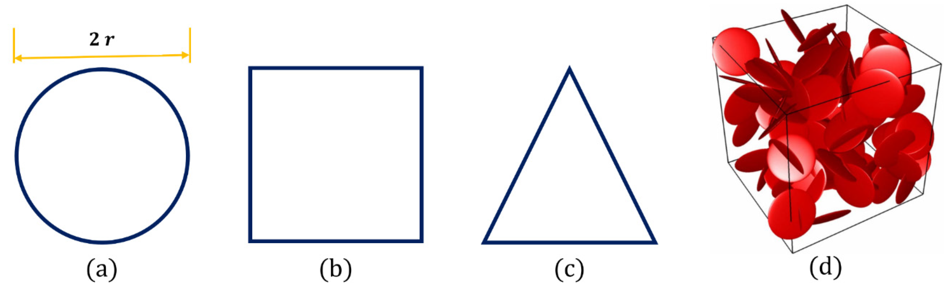
4.1. Geometry of Renewable Carbon

The stress transfer from matrix phase (polymer) to dispersed phase (carbon filler) mainly depends on the molecular interaction at their interface. The geometry of carbon fillers is considered to be the key factor which would significantly affect the interactions between the filler and matrix, and a large number of numerical models have been devoted to reinforced polymers doped with carbon fillers of variable geometries. The different geometry generates differences in the filler size, which contributes to the phase-localization and phase-separation behaviors in the composite blends.
It has been theoretically verified that a significant reinforcing effect of nanofillers could be achieved via the formation of a thick and strong interphase between the matrix and fillers. Thus far, the fact that isotropically distributed phases percolate at lower filler volume in the two-dimensional (2D) system has been well documented, but the quantitative determination of the geometric effects in the three-dimensional (3D) system was relatively recent. This is especially critical for carbon fillers, considering their complex structure, which would lead to an intensive computation demand. Yi et al. carried out a Monte Carlo study to investigate the percolation threshold of interpenetrating plates with different geometry, i.e., circular, square and triangular (Figure 9a–c), which were dispersed in 3D space [34]. Percolation model was established to elucidate the effect of filler distribution on the interfacial energies and particle-surface energy between different components in the system. Shown in Table 1 are the normalized percolation points (ηc), which were estimated by extrapolating the data to zero radius. The circular shape, ηc of 0.9614 ± 0.0005, tends to decrease the interparticle connectivity and has the highest percolation point. The 3D computer realization of 100 circular plates in random distribution is shown in Figure 9d. Similarly, Mathew et al. conducted Monte Carlo simulations on the percolation behavior of hard platelets in 3D continuum systems [35]. Cut-spheres, generated via intersecting a sphere with two parallel planes at equal distance from the equatorial plane, were used in their model, to represent the hard platelets. The simulation results indicated the platelets with lower aspect ratios required a relatively lower percolation threshold. Note that the majority of related works neglected the physical properties of the system, and only a few studies in the technical literature are devoted to the mechanical strength of the filler-doped composites.
The percolation behavior of ellipsoids’ disks has been the specific subject of several other studies. Ambrosetti et al. conducted a numerical study to evaluate the percolation networks of oblate ellipsoids of revolution surrounded with penetrable matrix [36]. Their results indicated that oblates with higher aspect ratios approach a pseudo-disk geometry, though still differentiated from an ideal circular disk. This was in good agreement with their later work, which expanded their initial study and investigated the percolative properties of nanocomposite regime doped with ellipsoids of revolution [37].

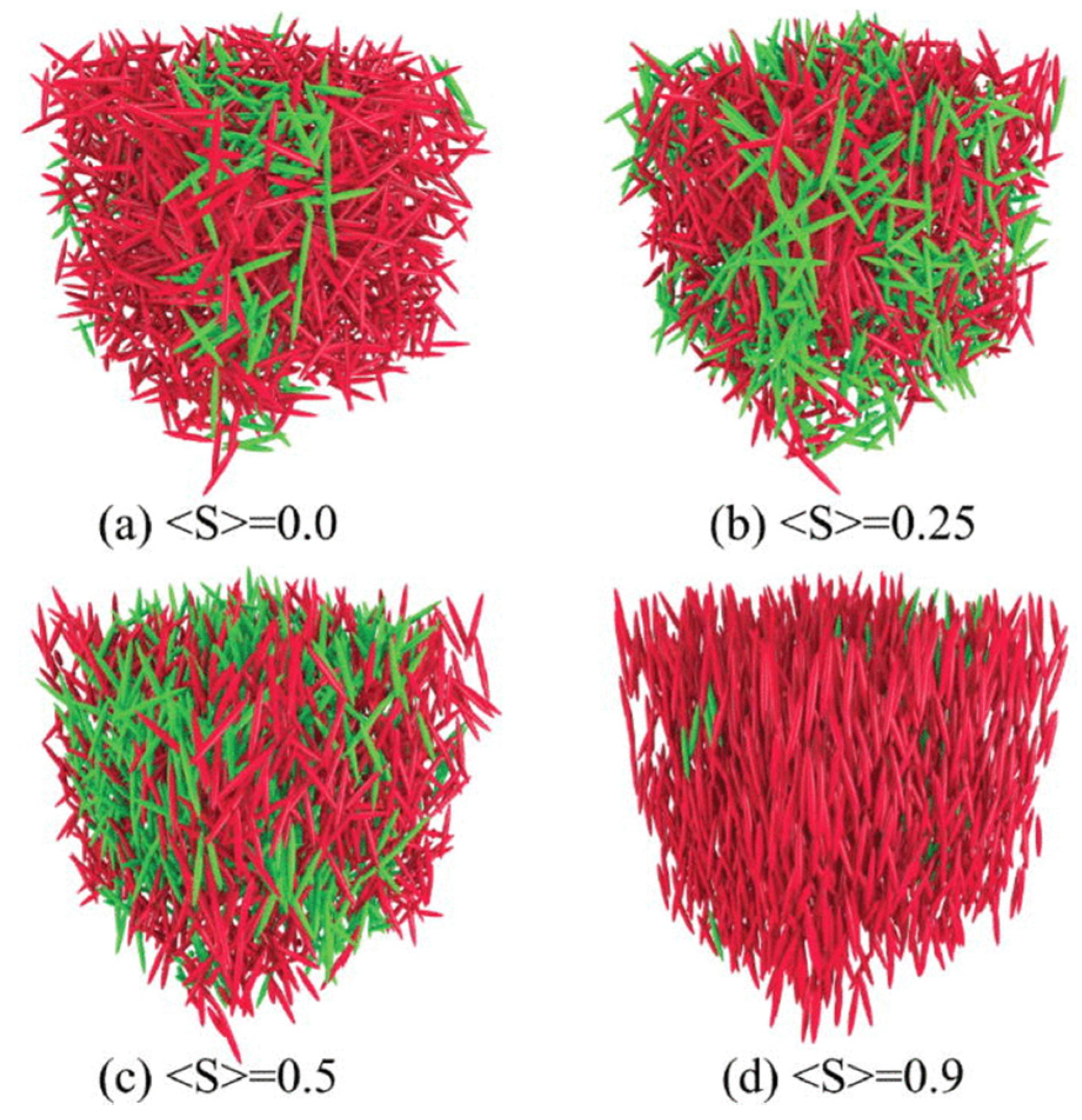
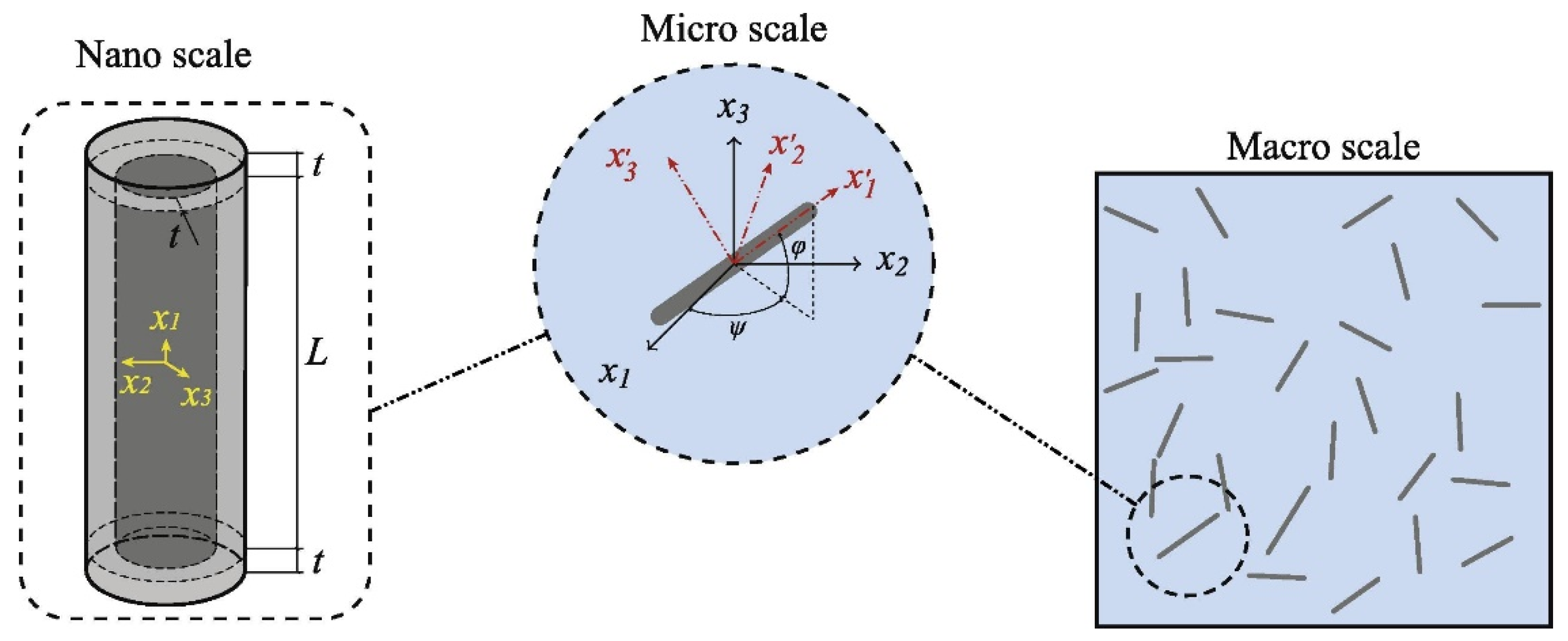
4.2. Alignment of Renewable Carbon

The alignment of renewable carbon is another important factor which affects its percolation behavior. Empirically, the ideal distribution of fillers throughout the composite is very application dependent: for most of the mechanical properties, a higher loading is preferred, as it can be aligned in the direction of the load, whereas for conductive capacity, a random percolated network is more desirable with as low of a loading concentration as possible. In the scenarios of multifunctional applications, the required microstructures may therefore even be contradictory.
In most of the packaging composites, an isotropic distribution of filler orientations is preferred. Renewable carbon, as highly anisotropic fillers, tends to get aligned under shear forces. These increased alignments would negatively affect the interconnectivity among the filler particles, thus increasing the percolation threshold. Moreover, during the synthesis of composites, the van der Waals attraction between renewable carbons is capable of generating aggregates and agglomerates. The strong interfacial interaction between renewable carbon and polymer may form a third phase, which further exacerbates the alignment of renewable carbon in certain directions. Such directional dependence might be of deterioration for extensive applications due to the maximum strength of material can only be reached in a preferred direction. It is thus critical to afford the good dispersion of carbon fillers in the polymeric matrix to improve its overall properties. Otten et al. developed an anisotropic continuum percolation theory to study the effect of an externally applied alignment field and excluded-volume interactions on the formation of a percolating network [38]. Angular correlations between the elongated particles were investigated by combining the connectedness percolation theory and Onsager theory, of which the former was for cluster size and the latter was for the interplay between interactions and the alignment of field-induced particles. The results indicated that the system-spanning, self-assembled network that forms above a critical loading would break up at higher loadings, as shown in Figure 10, due to the interaction-induced enhancement of particles alignment. Upon approaching to the percolation threshold, the dimension of particle clusters diverged with the same critical exponent perpendicular and parallel with the field direction. For strong fields, the low-density percolation threshold would be suppressed completely, while for weak fields, the densities were preempted by the transition to a uniaxial nematic phase.
In another study, the effect of filler alignment on its percolation dynamic was investigated by using the Bethe-lattice mapping models [39]. The alignment of fillers would create spatial clustering thus affecting the interaction between fillers. The simulated results showed a significant dependence on the variance of orientation for the rod-like fillers. Kale et al. conducted a Monte Carlo simulation to investigate the percolative properties of monodisperse oblate and prolate hard-core soft-shell ellipsoids, which represented carbon nanoplatelets and nanotubes, respectively [40]. Their results showed that, for a highly aligned system of rod-like carbon, the simulation result was coincided with the second virial approximation-based predictions, while for the highly aligned disk-like carbon, the result was the opposite.
In a later work conducted by Khan et al., the enhanced alignment of multi-walled carbon nanotube (MWCNT) was realized via the application of DC electric fields during the epoxy-based composite curing [41]. The ultra-violet/ozone (UV/O3) treated MWCNT with a large amount of oxygenated functional groups were mixed with the epoxy resin in an acetone medium. The curing agent triethylenetetramine was afterward added into the milled degassing mixture and subjected to a DC-electric field for an accelerated curing under elevated temperature (Figure 11a). The preferential orientation of MWCNT was confirmed by the polarized Raman spectroscopy of a nanocomposite containing 0.3 wt% of aligned MWCNT in Figure 11b, which showed the intensity of G-band peak with the incident light applied parallel to the alignment was about 1.7 times of that measured with the incident light perpendicular to it.
Shown in Figure 12 are the SEM images of the fracture surface morphologies of neat epoxy and MWCNT-incorporated nanocomposites. The neat epoxy, as a typical thermoset polymer, displayed a smooth surface (Figure 12a); however, the surface turned rougher and showed directional crack patterns upon embedding with MWCNT (Figure 12b,c). For the nanocomposites without MWCNT alignment (Figure 12b), long and straight river markings can be observed in parallel with the crack propagation direction without deflection, indicating less of a restraining effect against the crack propagation. In contrast, the composites with aligned MWCNT alignment exhibited shorter and round-ended river markings (Figure 12c), which could force the cracks to bypass the MWCNT’s tortuous paths, known as the crack tip deflection and bifurcation mechanism. Additional toughening effect due to the crack-tip bridging and pullout of aligned CNT bundles was further confirmed, showing the pullout CNTs and bundles on the fracture surface were of as long as 6–700 nm (Figure 12d). The nanoscale MWCNT bridges shown in Figure 12e could provide strong resistance to the crack opening, thus significantly boosting the strain energy required for the crack propagation through the matrix and enhancing the toughness on the macroscopic scale. The further forcing cracked composites left pullout, as well as a cavity on the other side of crack plane (Figure 12f). This pullout mechanism may significantly enhance the toughness of MWCNT-epoxy composites.
Jalal et al. evaluated the effective mechanical properties of CNT doped polymeric composite based on the mesh-free method and an optimized neural network (ONN) method [42]. An isotropic polymer matrix was assumed. The CNT reinforcement is either functionally graded (FG) or uniformly distributed (UD) in the radial direction. Shown in Figure 13A is a schematic representation of carbon-nanotube-reinforced composites (CNTRC) cylinder, nanostructure and CNT coordinates. It was concluded that CNT was prone to get aligned in the composite due to its tendency to bundle or cluster together. The effect of CNT alignment on the modulus properties were simulated based on the governing equations of stress and strain vectors by using the Eshelby–Mori–Tanaka approach. Similarly, Shi et al. studied the effect of agglomeration of randomly oriented CNTRC on its elastic properties based on an analytical micromechanics model [43]. It was assumed that a number of CNT were aggregated, while the remaining ones were uniformly dispersed throughout the polymer matrix (Figure 13B). Their findings indicated that the superior mechanical properties could be possibly achieved only if the CNT was with straight shape and distributed uniformly inside of the polymer.

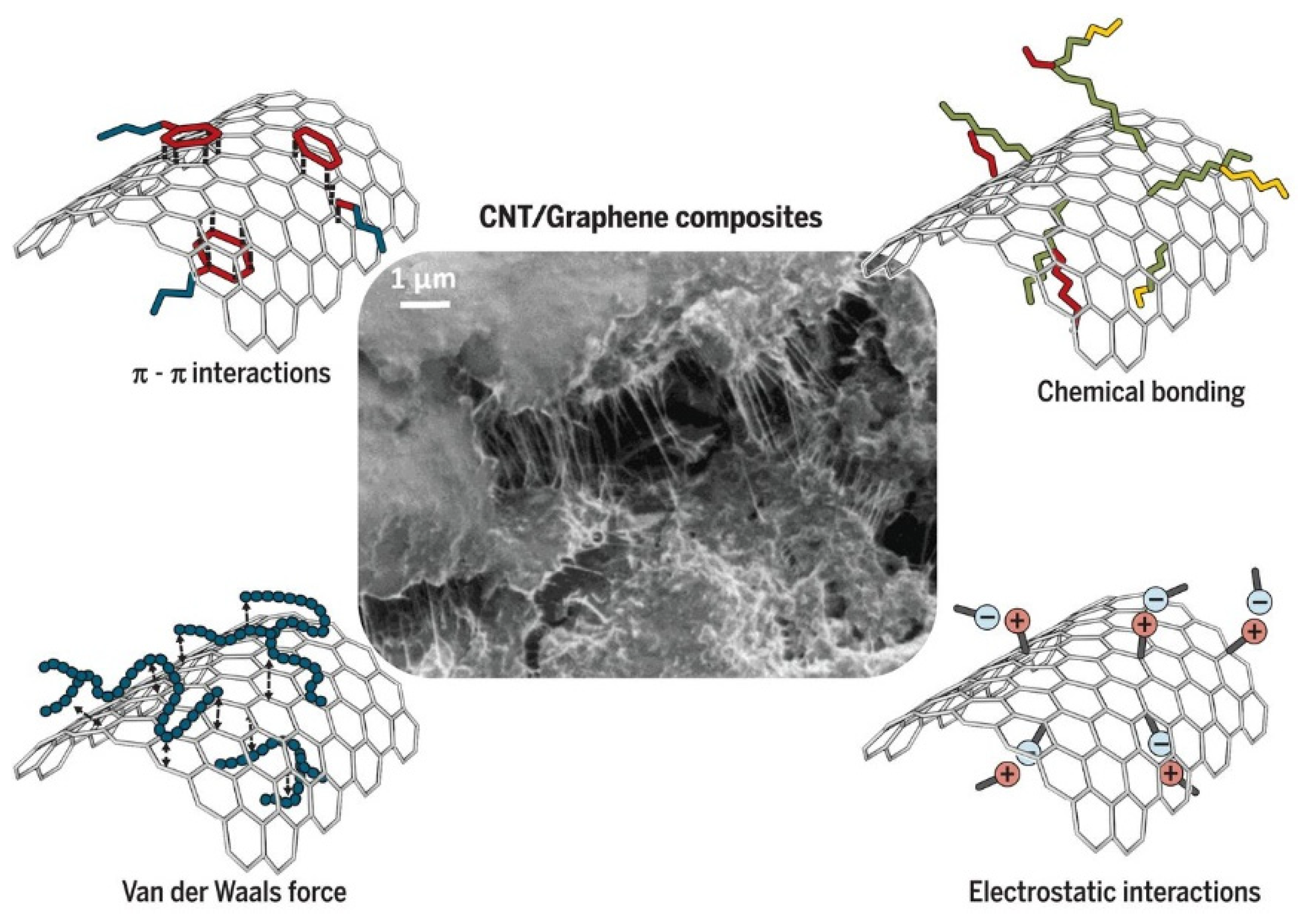
4.3. Surface Property of Renewable Carbon

Surface property is also a key factor deciding the percolation performance of the finished composites. Renewable carbon features with abundant functional groups and high specific area are favorable for chemical modifications. It is critical to select the proper surface treatments considering the easy aggregation of carbon particles owing to the strong van der Waals interactions between them. On the other hand, the attempts to over-modify the renewable carbon might generate nonuniformly dispersed bundles in the polymeric matrix, leading to poor interfacial connectivity and formation of mechanical stress concentration sites. The performance of nanocomposites would thus be affected. Therefore, it is important to chemically functionalize the renewable carbon without compromising their intrinsic properties [12]. Noncovalent modification method is capable to partially solve the dispersion problems but is ineffective to address the interface challenges. Therefore, increasing efforts have been put to develop the systematic and engineering approaches to design the functionalized carbon with both good dispersion and strengthened interfacial connectivity. As a consequence of these strategies, the storage moduli and relaxation process of the prepared nanocomposite would decay more slowly over the one made from pristine carbon.
Kinloch et al. proposed the multifunctional carbon composite model by combining the best features of continuous CNT and chemically functionalized CNT or graphene carbon, inside of the modifiable polymer matrix (Figure 14A) [12]. It was expected that the mechanical property of multifunctional carbons could exceed that of conventional carbon fibers for their use as structural reinforcements in composites. The best load-carrying capability ever achieved yet could thus be reached, which may evoke the potential of using multifunctionalized carbon to replace current carbon fibers, if properly designed and manufactured, for making high strength yet ultralight structures. Figure 14B further illustrates the loss modulus and electrical conductivity with respect to interfacial volume fraction in CNT or graphene carbon nanocomposites. The loss modulus, which represents the viscoelastic damping behaviors, increased linearly as the interfacial volume fraction increased within the low loading range. However, at higher volume fraction (depicted as saturation zone), no further increase in loss modulus was observed, mainly due to the constrained mobility of polymer chains. As for electrical conductivity, it shifted from insulating to conductive regimes as the interfacial volume fraction increased beyond percolation threshold (displayed in an S-curve). In another study, Mitchell et al. synthesized the functionalized single-wall CNTs (SWCNTs) via the in situ reaction of organic diazonium compounds [44]. The prepared 4-(10-hydroxydecyl) benzoate-SWCNTs particles were then used for the fabrication of nanocomposites, which exhibited the percolated SWCNTs network at 1% of loading. While for the nanocomposites prepared from the pristine SWCNTs, the percolation occurs at twice of the fillers’ loading. This phenomenon was attributed to the enhanced interaction and dispersion of chemically modified carbon tubes within the polymer matrix.
Graphite oxide, as a layered carbon material produced by the oxidation of graphite, has multiple functional groups such as hydroxyl, carbonyl, carboxyl and epoxide groups [45]. These hydrophilic groups allow the graphite oxide carbon to be well-dispersed in the aqueous medium; however, they are incompatible with most organic polymers. Surface functionalization can potentially change their intrinsic properties, thus eliminating their irreversible coagulation within a polymer matrix. Stankovich et al. chemically modified the graphite oxide carbon by using organic isocyanates, and the resulted isocyanate-derivatized carbon was with lowered hydrophilic character [46]. The isocyanate treatment is capable of generating amide and carbamate ester bonds via the reaction with the carboxyl and hydroxyl groups, respectively. This would be favorable for the modified carbon to form stable dispersions and generate the completely exfoliated carbon sheets with thickness around 1 nm. The individual carbon sheet could be well-dispersed into the polymer matrix, which was directly correlated with its positive effect on the mechanical strength improvement. Moreover, at loading concentration of 2.4 vol.%, the composite appeared to be almost entirely filled with the carbon sheets, even though its majority component was polymer (97.6 vol.%). This ‘visual’ effect is mainly attributed to the large surface area of the carbon sheet (specific surface area of 2600 m2/g for an individual carbon sheet). The high aspect ratio and surface-to-volume ratio of the modified carbon would significantly facilitate the preparation of graphene oxide (GO) carbon-based composites. Similarly, Nawaz et al. covalently functionalized GO carbon with octadecylamine (ODA) and added into thermoplastic polyurethane (TPU) as model additives [47]. The mechanical properties of the composites were characterized and showed no increase in stiffness or low-strain stress at loading levels below 2.5 vol%. However, above this threshold, the functionalized carbon formed a percolating network and both mechanical quantities increased as a power law with the increase of volume fraction. It was concluded that the formation of this network, other than interfacial stress transfer, would act as a jammed system for dominating the mechanical properties.
It may be noted that the performance of carbon-based composites is kind of sensitive to the preparation method and polymer matrices, even when the same modified carbon materials are used. For example, Jiang et al. prepared the polyimide (PI) composite by in situ polymerization, using modified multi-wall carbon nanotubes (MWNT) as fillers (Figure 15a) [48]. Their results implied no significant improvement in the mechanical properties of composite by addition of MWNT (only about 6% maximum increase in Young’s modulus, as shown in Figure 15b) at the percolation threshold of ca. 0.15 vol%. While Shaffer et al. used the same category of MWNT carbon material for poly(vinyl alcohol) composite and the percolation threshold was ranged in 5–10 wt% [49].
As for the preparation procedure adopted by Jiang et al., the MWNT was firstly treated in N,N-dimethylacetamide (DMAc) under ultrasonic to form the loose networks, which is a critical step for making a uniform dispersion of MWNT into polyimide [48]. The monomers, pyromellitic dianhydride (PMDA) and equimolar amount of 4,4′-diaminadiphenyl ether (DADPE) were then added into the DMAc solution to obtain the PMDA-DADPE polyamic acid (PAA)-MWNT solution after stirring for 3 h in the nitrogen gas, at ambient temperature. The PAA-MWNT solution was cast onto plate glass, followed by the dry and curing process, to form the PI-MWNT composite film. The SEM patterns in Figure 16a,b show a layered structure consisting of carbon particles covered by the polymeric matrix. It was conjectured that MWNT was capable of promoting the nucleate crystallization on its surface, which may interrupt the direct contact of carbon tubes, thus restraining the performance improvement of the composite.

5. Percolation Models

Percolation model is of practical meaning to simulate the migration/diffusion behavior of fillers in the mechanical reinforcement of packaging composites. So far, a variety of mathematical and analytical models has been introduced, some of which with completely different scaling and universal properties from the original approach. Meanwhile, from the modeling aspects, the majority of works related to high-performance composites doped with renewable carbon has been mostly experimental, and only few numerical and analytical models on this subject are established in the technical literature. Active carbon, derived from nonrenewable source, were more frequently reported and typical examples can be found as graphene and CNT [50,51].

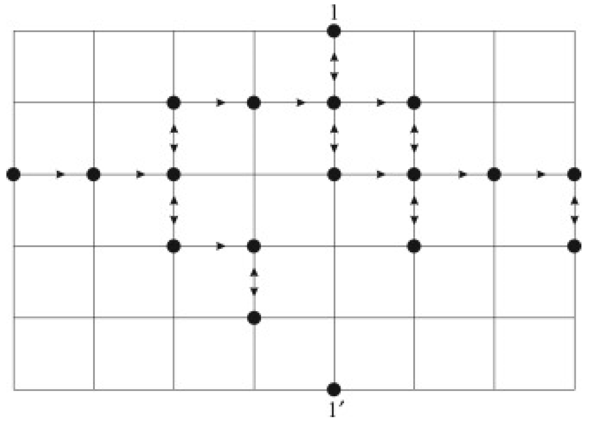
5.1. Directed Percolation and Semi-directed Percolation

Directed percolation is a mathematical system which displays nonequilibrium phase transitions. It needs certain prerequisites, such as the absence of additional symmetries, conservation laws or long-range interactions, as well as the existence of a unique absorbing state. Within the directed system, the lattice is sensitive to particle properties and the probability of connectedness are adjustable. Technically, an active state can propagate through connected bonds on a fixed grid with a probability, P, and proliferation occurs only via the neighbor interactions. Percolation would be solely governed by parameter P, and the transition between different phases mainly depend on the Reynolds number [52]. In directed percolation, there is an exact critical point of probability, Pc. At P < Pc, the system would return to the passive state; P = Pc corresponding to a continuous phase transition; while at P > Pc, the fraction of active states is beyond zero [52].
For the semi-directed percolation, it can be treated as an intermediary model between the directed percolation and isotropic percolation model (Figure 17). Various studies of closely related models of semi-directed lattice have been conducted through general random mathematical networks [53]. Knežević et al. established a semi-directed percolation model on the square and triangular lattices by using the transfer-matrix and phenomenological renormalization approaches [54]. A good numerical estimation of both critical exponents and critical probabilities were obtained by doubling the finite strips size. The simulation results provided numerical evidence that semi-directed percolation belonged to the universality class of the fully directed percolation model. This conclusion was supported by other studies of semi-directed self-avoiding walk simulations, showing that they, indeed, have the same critical properties as corresponding fully directed models.

5.2. Tunneling Percolation

Tunneling percolation model has been suggested to describe the structural properties of disordered network systems in which percolation coexists with tunneling behaviors. Examples of such systems were provided by various filler-doped-polymeric composites [55]. Tunneling model generally assumes an isotropic distribution of fillers, without considering their relative orientation. It is thus with limitation to evaluate the effect of anisotropy in tunneling orientation on the mechanical and surface properties of the composites. Two primary approaches are currently available to estimate the threshold of tunneling percolation, namely Monte Carlo (MC) simulation and analytical approximation, of which the former was proved to be more effective in computational simulation.
MC simulation is a powerful mathematical technique to study the interactions between multiple particles or bodies in the presence of local or external fields. It has been widely used to investigate the filler-polymer binary composites in both 2D and 3D model. For 2D modeling, the migration behavior of additives is simulated into a square domain. The alignment is expressed as a function of angular distribution between [0, π] for anisotropic case. For 3D simulation, the filler alignment is correlated to the distribution of angle θ between the axis and a specified direction. For rod-shaped additives, one angle is sufficient to describe the alignment considering their axial symmetry. The orientation distribution function (ODF) was proposed as Gaussian distribution in cosθ by Chatterjee et al., and its expression is expressed as Equation (5) [39]:
p ( θ ) = a + b | cos θ | m
Kale et al. followed this assumption and investigated the tunneling-percolation behavior in polydisperse ellipsoids [40]. Two parameters, <S> and <S2>, were introduced. <S> stood for the orientational order parameter, and its angular brackets stood for the ensemble averaging of total fillers. 〈S〉 is 1 for the fully aligned fillers and is 0 for the isotropic orientations. The results from the simulations showed that, as the <S> decreased from 1 to 0, the percolation threshold decreased in the alignment direction. This behavior is attributed to the enhanced connectivity between fillers as the alignment diminished. <S2> is its second moment, which is expected to affect the performance of composites as well.
Shown in Figure 18 is the model established based on ODF proposed by Chatterjee et al. In this model, 〈S〉 and 〈S2〉 can be independently altered. The distribution of azimuthal angle β is chosen between [0, 2π], which is independent from the distribution of θ. The normalization condition for p(θ) requires the following:
0 2 π 0 2 π p ( θ ) s i n θ d θ d β = 1
The condition which was given in Equation (5) shows that a  +  b / (m  +  1) =  1/4π. Thus, the 〈S〉 and 〈S2〉 can be expressed as follows:
S = 4 π b m ( m + 1 ) ( m + 3 )
S 2 = 1 5 [ 1 + 2 ( 2 m + 1 ) S ( m + 5 ) ]
Two free parameters, 〈S〉 and m, are available to control the distribution, due to the imposed normalization condition. The minimum value of m for the ODF can be thus obtained as follows:
m m m i n = 3 S 1 S
In the simulations, fillers were modeled as spheroids, and their orientation was determined by choosing θ according to a distribution obtained for given 〈S〉 and m. Aspect ratio was defined as the ratio of polar and equatorial semi-axes. The desired volume fraction of fillers was achieved by adding fillers one by one to the square domain, ensuring that there was no entanglement between the fillers. Periodic boundary conditions were implemented in all three directions.
The effect of filler alignment on the mechanical properties was also studied by Silva et al. based on the tunneling-percolation model [56]. Their MC simulations resulted in an increase in the mechanical strength, as the fillers’ alignment decreased. A similar conclusion was reported by White et al., who identified a critical orientation Sc at a given aspect ratio and volume fraction of the fillers. The mechanical strength of their samples exhibited a significant increase under Sc [57].

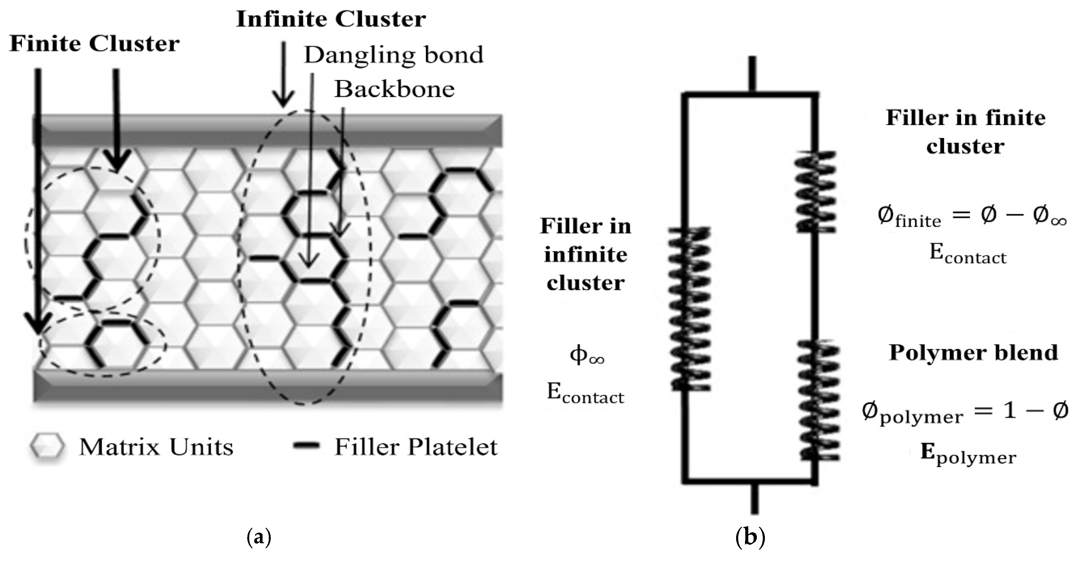
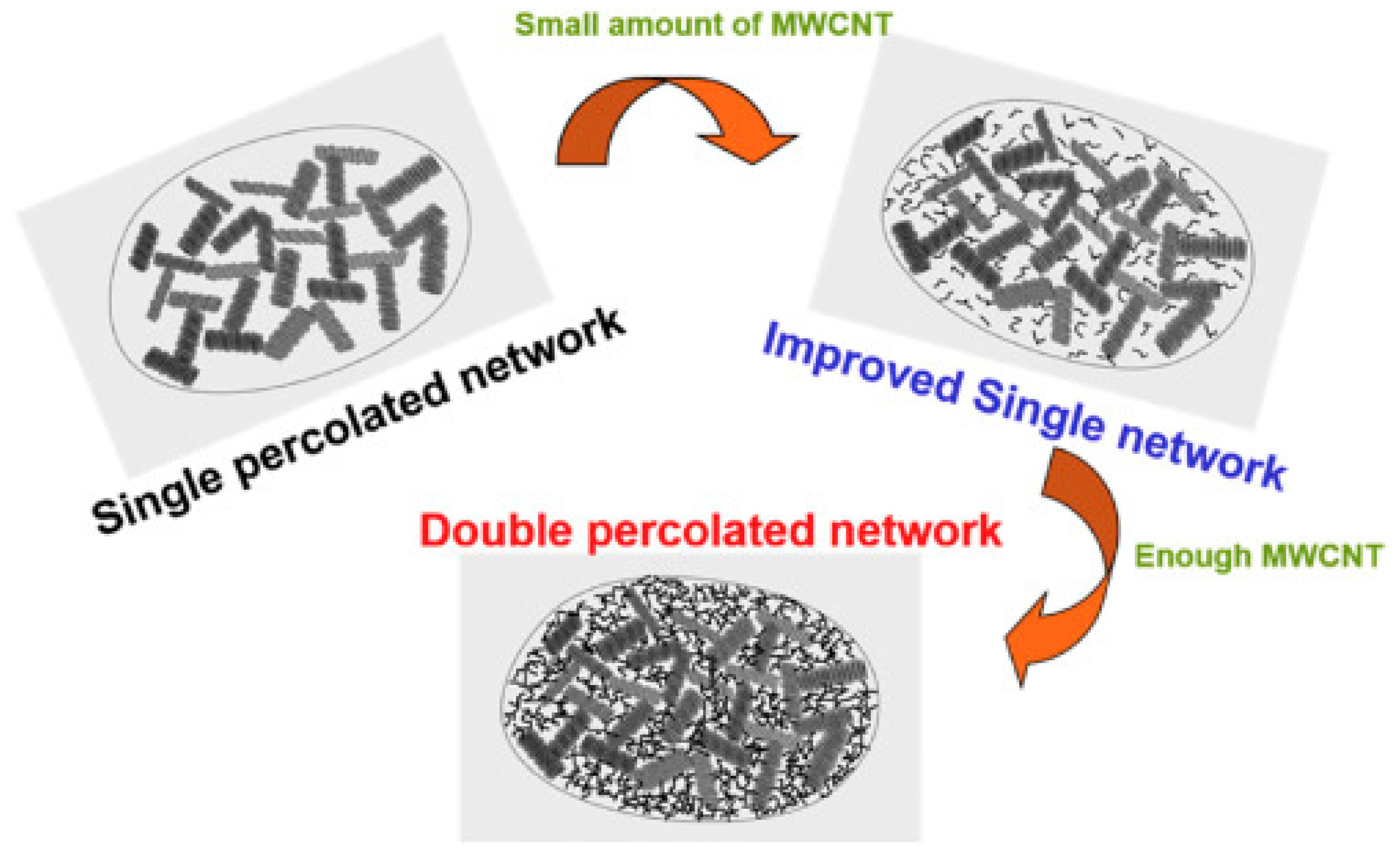
5.3. Dual Percolation

Dual percolation refers to the double percolation processes which take place simultaneously inside of the matrix. The eventual percolation threshold is mathematically equal to the product of individual percolation thresholds, based on the scaling theory. A lower concentration of filler is thus requested to improve the mechanical properties of composites. This is beneficial for designing the ultralow filler-loaded reinforcing polymeric composites. Moreover, the dual percolation can also be used to describe the critical transitions in other disordered systems which typically have a random geometric structure. The percolation threshold is generally dependent on the structural factors, which are closely related to the connectivity of stress volumes, such as molecular weight and the aspect ratio of filler–filler/filler–polymer agglomerates.
Wu et al. fabricated the dual percolated network by combining the loosened large-sized expanded graphite (EG) and dense tiny-sized multi-wall carbon nanotubes (MWCNT) in polypropylene (PP) through a simple melt blending method [58]. Shown in Figure 19 is the proposed dual percolation schematic diagram. Within this network, EG sheets were well connected, while still having certain vacancies, which could be filled by the further addition of tiny-sized MWCNT with a length of only 1.5 μm. MWCNT could sufficiently entangle with each other when its concentration reached to percolation threshold, thus forming a dense network in the EG vacancies for the heat and electron transferring. The prepared PP/EG-MWCNT ternary composite was reported with an excellent electromagnetic interference (EMI) shielding behavior, as well as increased electrical and thermal conductivity. The multiple interaction mechanism in their dual percolated network was concluded as a key factor in reducing the interface thermal resistance of MWCNT compared with the single filler composites. In another study, Wie et al. incorporated two immiscible polymers, poly(methyl methacrylate)(PMMA) and polystyrene(PS), with multiwalled carbon nanotubes (MWCNTs) for the preparation of high-performance composites [59]. Their results revealed that MWCNTs were selectively localized in PMMA phase, which was favorable to form a dual percolated network at the same filler loading. Shown in Figure 20 are the Infrared camera images of PS/CNT, PMMA/CNT and PMMA/PS/CNT samples that represent the effect of dual percolation. The color of samples became brighter as the temperature increased, indicating the effect of phase separation within two polymers. Apparently, PMMA/PS/CNT had the brightest color among the three samples.
A similar concept was adopted by Rong et al., who prepared the polypropylene (PP) composites via doping with the nanofiller [60]. Nano-silica was used in their case, instead of carbon materials, and it was grafted by the irradiation-pretreated polystyrene (SiO2-g-PS). Their tensile test results confirmed the effect of filler addition on the strength toughening due to the enhanced interfacial stress-transfer efficiency. As shown in Figure 21a, an improved adhesion was obtained as the filler content exceeded the critical value of 0.65 vol%. The microstructure analysis of composites revealed the dual percolation dynamics which simultaneously occurred in both SiO2-g-PS agglomerates (dispersed phase) and the polypropylene host matrix. This was mainly attributed to the superposition of stress volumes around the single filler and inside of the dispersed agglomerates. Figure 21b illustrated the variation in the toughness of SiO2-g-PS/PP composites characterized by the area under the stress–strain curves as a function of fraction of stress volume, φs (Equation (10)). The critical stress volume fraction φsc, which is defined as the peak position of the first derivation of the area with respect to the stress volume fraction, was estimated as being 51%. The percolation behavior at the shear-yielded zones is beneficial for lowering the overall percolation threshold while maintaining or enhancing the performance.
φ s = ( d + τ c d ) 3 V f
where d stands for the particle diameter, τc stands for the critical matrix ligament thickness and Vf stands for the particle volume fraction.

5.4. Other Models

5.4.1. Halpin–Tsai Model

The Halpin–Tsai model for two-dimensional in-plane unidirectional of carbon fillers is widely used for the simulation of mechanical properties of the filler-reinforced polymer nanocomposites (PCNT) [61]. It correlates the modulus of PCNT to many parameters, such as filler content, geometry and filler modulus [62]. In most of these studies, the modified Halpin–Tsai equation, as shown in Equation (11), was adopted by integrating the orientation factor, α [63,64]:
E c E m = 1 + c η v f 1 c η v f   ,   with   η = ( α E f E m ) 1 ( α E f E m ) + c
in which c = 2(λ/d) refers to a constant shape factor relating to the aspect ratio of reinforcement length (λ) over the diameter (d); Ec, Em and Ef refer to the modulus of composite, matrix and filler (carbon); and vf refers to the volume fraction of carbon filler. As for α, its value of 1/3 is generally used for the Young’s modulus of composites, in the case that the length of filler is greater than the thickness of specimen (fillers are assumed randomly oriented in two dimensions); however, the value of 1/6 or 1/5 is used if the filler length is much smaller than the thickness of specimen (fillers are assumed randomly oriented in three dimensions) [65]. For carbon doped polymeric composites, α of 1/6 is more widely employed, considering the much shorter length of carbon particles when comparing them with the thickness of specimens [66].
However, it was later reported that the linear description of mechanical modulus using the Halpin–Tsai equation was restricted in a relatively narrow concentration range. At high load volume, carbon particles were entangled and aggregated more severely so that their reinforcing effects would be compromised. Yeh et al. thus introduced an exponential shape factor, ξ, to replace the factor c in Equation (11) [66]:
ξ = 2 ( λ d ) e a v f b  
Moreover, the modified Halpin–Tsai equation was expressed as follows:
η = ( α E f E m ) 1 ( α E f E m ) + ξ
where a and b were constants, related to the degree of carbon agglomeration, and account for the nonlinear behavior of the Halpin–Tsai model as the carbon content increased to the semi-diluted region. Wu et al. used both the Halpin–Tsai equation and modified Halpin–Tsai equation to describe the linear and nonlinear mechanical behaviors of the biodegradable polylactide composites (PCTs), which were prepared by melt-mixing with the carbon nanotubes (CNTs) with high aspect ratio (HAR) and low aspect ratio (LAR), respectively [65]. Their results showed that the HAR CNTs were much more flexible in the polylactide matrix than the LAR CNTs. At low loading levels, the former was dispersed as self-entangled flocs, whereas the latter was dispersed as bent fibers or bundles. However, at high loading levels, both were presented as flocs due to the strong interfacial interactions. Sun et al. conducted a study on both static and dynamic mechanical behaviors and electrical properties of carbon nanofiber (CNF)-reinforced epoxy nanocomposites, by varying the CNFs content [63]. The modified Halpin–Tsai model was used to evaluate the Young’s modulus and storage modulus, and a good fit between the predicted values of Young’s modulus and the experimental data was achieved. The highest tensile strength was found at the CNF content of 1.0 wt%, and the alternate-current (AC) electrical properties of the CNF/epoxy nanocomposites exhibited a typical insulator–conductor transition with percolation threshold of 0.057 vol% CNF.

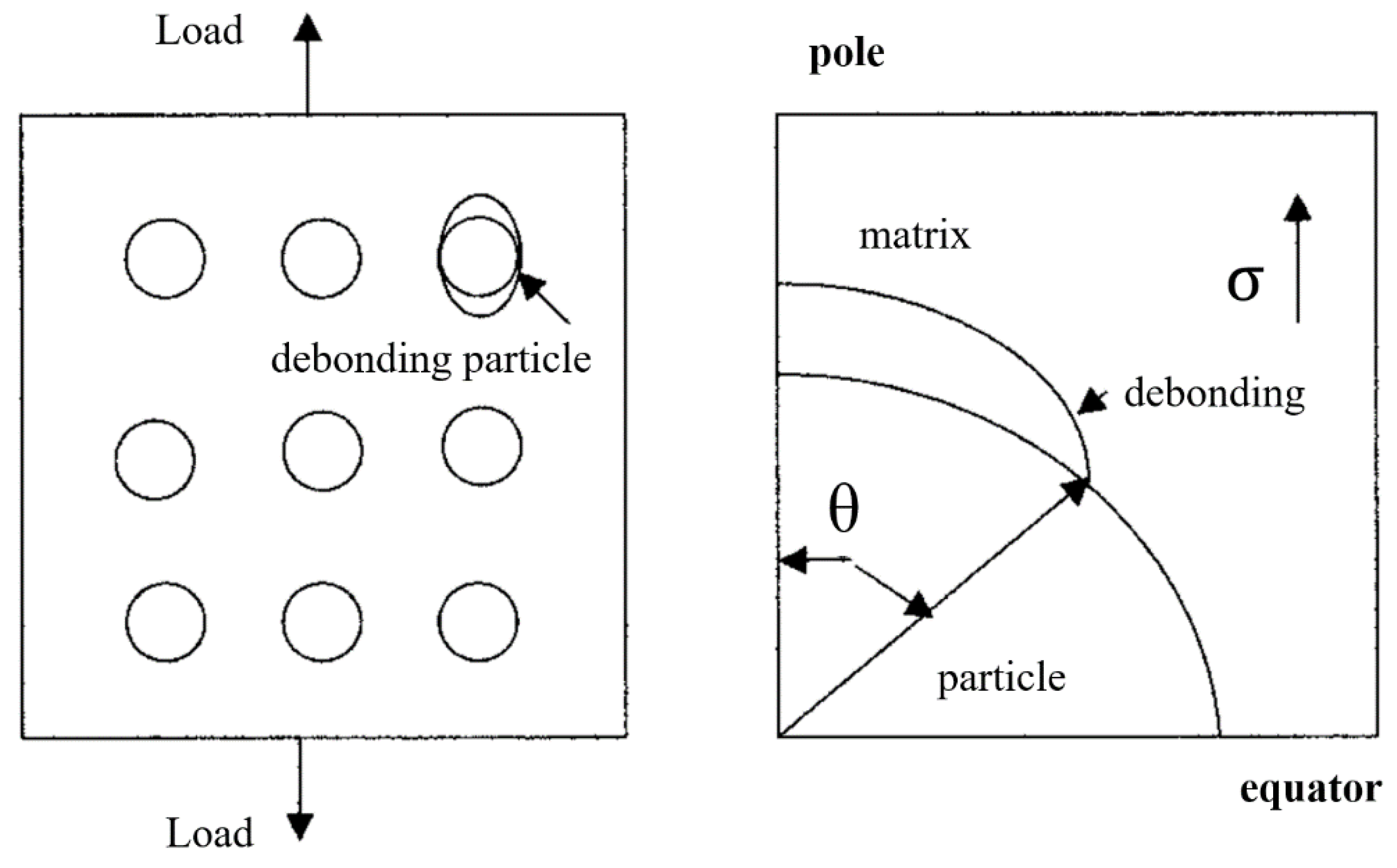
5.4.2. Debonding Model

For certain rigid-fillers reinforced binary composites, the filler-particles will not deform when external loading is applied, because the Young’s modulus of fillers is much greater than that of the polymer matrix. As the loading exceeds the interfacial adhesion between the fillers and polymer matrix, debonding at the interface will occur first and generate the micro-voids. The deformation restraint of the composites around the fillers could thus be released and create an extensive elastic deformation to absorb the strain energy. This phenomenon is also named as “brittle–ductile transition (BDT)”, and its typical process follows the percolation mechanism: The yielding of the matrix initiates from the local area and then propagates to the entire region, under the action of external forces. The enhancement of the interfacial bonding thus becomes a main factor for the reinforcing mechanism. Liang et al. reviewed the advance studies on rigid inorganic particulates filled poly(propylene) composites, and their toughening and reinforcing mechanisms were interpreted by debonding model [67,68]. The key to the reinforced polymers was concluded as that the fillers should be able to induce the large polymer deformation via interfacial debonding and end the propagation of cracks. It was desirable for the fillers to be encapsulated with an thin elastic layer to form a soft shell/hard core structure so that to simultaneously toughen and reinforce polymers. The results showed that the addition of rigid inorganic particulates into poly(propylene), a semicrystalline thermoplastic, could cause variation in its crystalline grain size and thus be favorable to maintain the plane strain state and make the deformation of matrix difficult. Three types of interfacial adhesion were classified based on the bonding strength: poor adhesion, some adhesion and strong adhesion.
In the case of a poor adhesion, little stress could be transferred between the interfacial layers. Therefore, the yield strength of particulates-filled polymeric composites mainly depends on the effective load bearing cross-section area fraction (1−Ψ), due to the absence of the particulates. If Ψ is a power law function of the volume of particulates, Vf, then we get the following:
σ yc = σ ym ( 1 a V f b )    
where σyc and σym refer to the yield strengths of composite and polymer matrix, respectively, while a and b refer to the constants related to stress concentration, adhesion and geometry of particulates (fillers). As for the spherical particles with no adhesion to the matrix, which fail by the random fracture, Equation (14) becomes the following:
σ yc = σ ym ( 1 1.21 V f 2 3 )
However, in the case of some interfacial adhesion, the interfacial layer could transfer certain stress, and then the debonding between the particulates and polymer matrix would be produced as the deformation increased. The yield strength was thus a sum of both forces, and the value of a in Equation (14) turned smaller than 1.21, whereas b = 1 as the samples failed by planar fracture. A debonding model was thus established by introducing a new parameter, bonding angle (θ) (Figure 22) [68]. The equation could be expressed on the basis of the assumption of cubic array of spherical fillers:
σ yc = σ ym ( 1 1.21 sin 2 θ V f 2 3 )
For the well-bonded fillers (strong adhesion), the stress could be transferred via a shear mechanism, and Equation (14) could be modified as follows:
σ yc = ( σ a + 0.83 τ m ) + K σ a ( 1 V f )

5.4.3. Generalized Method of Cells (GMC) Model

Generalized Method of Cells (GMC) is known as a three-dimensional model for evaluating the mechanical percolation properties of effective nanoscale composite when the critical threshold is reached [69]. The use of GMC model captures the effect of scale and the interfacial geometry surrounding the included phase, and it can be used to assess the mechanical strength of continuously reinforced nanocomposite in the transform domain based on the percolation theory [70]. As a periodic unit cell model, GMC uses a rectangular repeating volume element as the representative volume element (RVE) for a periodic microstructure. Every RVE composes of multiple subcells, with each one assigned the properties of one of the composite phases. The microstructure of nanocomposite is then described by a triply periodic stacking of RVEs. Upon applying the periodic conditions between these stacked RVEs, or between the subcells, the microstructure of GMC can be connected to an equivalent homogeneous material with a set of continuum level equations, thus predicting the effective properties [70]. Moreover, specific boundary conditions, which are satisfied in an average sense and integrated over the boundaries, can enforce the continuity of displacements and tractions across the subcells by minimizing of the effect of rectangular geometry [71].
In a previous study, Snipes et al. used the GMC model for the simulation of a three-dimensional nanoscale composite, to predict its effective viscoelastic property [70]. Scale was introduced by referencing the dimension of interfacial regions to that of the nanofillers. Effective viscoelastic properties were developed for varying interfacial elastic stiffnesses. Their results showed a significant increase in the stiffness in response to an “instantaneous” step load, which corresponded to a reduction in the rapid creep response and a rapid leveling off of the time-dependent strain curves, until a plateau or threshold was reached. This threshold was below the stiffness of the included nanophase, which might be attributed to the sizable volume fraction of a third phase. It suggested that the surface derivatization of nanofillers might be beneficial to generating a more compliant surrounding interface for a tunable creep response behavior.

5.4.4. Other Micromechanics Models

Micromechanics-based theory has been proven to be a powerful analytical approach for simulating the mechanical properties of double-phase composites. The well-known micromechanics models include the Mori–Tanaka method [72], self-consistent method [73,74] and differential method [75], among others. Of these models, the most widely adopted approach is the Mori–Tanaka method, though it always gives a higher prediction of the elastic modulus than the experimental results [76]. Taya et al. summarized the role of Eshelby’s micromechanics models in different selected smart composites based on the Mori–Tanaka theory [77]. These smart composites included piezoelectric composites, shape memory alloy (SMA) fiber composites and piezoresistive composites, which exhibited coupling among mechanical, thermal and electromagnetic behavior. The predictions based on these micromechanics models were in accordance with the limited experimental data. In a later work, Loos et al. derived and compared different micromechanics models in the prediction of elastic modulus of polymer/CNT composites [78]. Their results confirmed the variable suitability of these models, under the changed test conditions. The fitting data showed that a significant enhancement of modulus took place up to the percolation threshold, above which the reinforcement efficiency decreased dramatically. García-Macías et al. recently employed the electrical counterpart of a mean-field homogenization model of Eshelby–Mori–Tanaka to estimate the effective properties of a heterogeneous volume element (RVE) [79]. Shown in Figure 23 is a representative RVE in multiscale, which depicts the two-phase composite consisting of a cementitious matrix doped with a volume fraction f of straight and randomly oriented carbon fillers. An RVE designated a macroscopic area from the composite as a representative for the material microstructure, so that sufficient carbon fillers could be considered within the RVE, to statistically represent the overall properties of composite [79,80].
It was believed that the agglomeration of carbon fillers was the origin of its spatially inhomogeneous distribution within the composite, and the corresponding clustering effect is sketched in Figure 24. The bundles were assumed to be ellipsoidal carbon fillers with different properties from their surrounding matrix. The two-parameter agglomeration model was applied to describe the total volume, Vr, of carbon fillers in the RVE [81]:
V r = V r bundles + V r m
where V r bundles and V r m are the volumes of carbon fillers agglomerated in the bundles and dispersed in the matrix, respectively. Moreover, two more agglomeration parameters, χ and ζ, were introduced specifically for characterizing the clustering behavior:
χ = V bundles V
ζ = V r bundles V r
where Vbundles is the bundles volume in the RVE, χ is the volume ratio of the bundles with respect to the total volume of RVE and ζ is the volume ratio of carbon tubes that are dispersed in bundles with respect to the total volume of carbon tubes. A higher χ means a more homogeneous distribution, and at χ = 1, the carbon fillers reach to a fully uniform dispersion. On the contrary, ζ = 1 represents the state in which all the carbon fillers are agglomerated.
Moreover, it has been suggested that the interphase zone exists between the carbon fillers and their surrounding polymer matrix, and it would play an essential role in determining the elastic properties. Accordingly, certain methods, such as differential replacement method (DRM) and uniform replacement method (URM), which account for the inhomogeneity at the interphase zones, can be used to study the effective elastic modulus of composites [76]. These methods are capable of converting a three-phase, which includes fillers, polymer matrix and their interphase zones, into a two-phase with randomly oriented fillers surrounded by the inhomogeneous matrix. The resulted two-phase system can then be simulated by any existing micromechanical models mentioned above, to predict the overall effective properties based on Equation (21) [76]:
C eff = C i + C i C i C f C i + ( 1 ) α C i
where ∅ = (r0/r1)m refers to the volume fraction of fillers in the two-phase system, with r0 and r1 as the inner and outer radii of the interphase region, and m of 2 or 3 for fillers; the superscripts “eff”, “i” and “f” refer to the effective property, interphase and fiber/fillers, respectively. The α C i relates to the Poisson ratio of the interphase and boundary conditions of the far-field loading. Feng et al. simplified the carbon nanotubes as straight cylindrical tubes, and the carbon particles together with their surrounding interphases were simulated as equivalent solid fillers, due to the electron hopping, thus turning the composite into a two-phase system for micromechanical modeling [80]. A good agreement between the modeling results and the experimental data was achieved for both single-wall and multi-wall carbon-nanotube-based nanocomposites. The simulation results indicated that the size of carbon nanotubes had significant effects on the percolation threshold.
However, it is also well accepted that most of the classical micromechanical models were not capable of capturing the percolation threshold at an extreme low volume fraction of carbon fillers, even though multiple heterogeneities would be considered in the investigation of the effect of interaction networks and reinforcement dispersion. For this reason, Kim et al. adopted an analytical homogenization approach for composites containing multiple heterogeneities to predict the percolation threshold effect by using the hard/soft core concept [82]. The composites were with matrix of polymerized cyclic butylene terephthalate (pCBT) and compounded with nanocarbon-fillers, based on a method of solvent-free powder-mixing and in situ polymerization. Their results showed the carbon fillers, with various size and shapes, were uniformly dispersed within the pCBT matrix. The comparison of the experimental data and predicted values confirmed that the percolation threshold and tunneling effect of reinforcements were successfully captured by this newly developed model.

6. Nanocellulose: Carbon-Based Reinforcing Filler

Nanoscaled materials hold the power to revolutionize the field of composites, due to their strikingly distinct properties from the bulk counterparts. Nanocellulose, a unique type of carbon-based reinforcement filler, consists of molecular chains of anhydro-D-glucopyranose units (AGU), with each having three functional hydroxyl groups (Figure 25a) [83,84,85,86]. As for the chemical reactivity, the hydroxyl groups at the highly ordered region (crystalline) are more inert compared with those in the loosely organized region (amorphous) [87]. Shown in Figure 25b is the TEM image of rod-like nanocellulose which was reported by Sun, et al., with a width of 3–10 nm and length of 50–165 nm [8]. An isotropic distribution in the solvent medium was realized due to the surface negative charges derived from the sulfate groups. Nanocellulose possesses an excellent affinity toward different molecules. Shown in Figure 25c are the composites formed by nanocellulose rod-particles loading with Spirooxazine (SO) [88].
Nanocellulose has been successfully used for the manufacturing of packaging film. Sun et al. prepared the nanocellulose-based edible (BE) film via a modified nanofiltration setup using dialysis membrane [9]. The obtained film possessed desired mass transport properties and could be used as an effective barrier to oxygen by discriminating the molecular size and relative affinity between the gas and film matrix. Mechanical strength tests showed a significant increase in the tensile stress (from 0.08 to 0.17 MPa) and auto module (from 0.9 to 3.1 MPa) of BE film, comparing with the control sample (co-blended film without the use of modified nanofiltration setup). SEM results revealed the uniform and smooth surface structure of BE film with a compact lamellar cross section. The swelling behavior was evaluated by the Schott’s second-order model in Equation (22):
t Q t = 1 k i s + 1 Q t
where Qt (g/g) refers to the swelling capacity at time t (s), Kis (g/g) refers to the swelling rate constant and Q (g/g) refers to the equilibrium swelling capacity. Figure 26a presents the swelling kinetics for both BE film and co-blended film, and a significant decrease in the swelling capacity (Qt, P < 0.05) was confirmed (swelling rate constant Kis decreased from 621 to 500 g/g; equilibrium swelling capacity Q, decreased from 454.55 to 434.78 g/g).
Both permeability and permeability ratio of the test gas (oxygen and carbon dioxide) increased as the relative humidity (RH) elevated (Figure 26c). Evidently, an exponential increase was exhibited beyond 50% RH. The decreased pore size and porosity were proposed as the main reasons for impeding the dissolution of molecules into the film. Two distinct stages, the pore-size-dependent stage and the gas-solubility-dependent stage, were identified with different diffusion mechanisms (Figure 26b): The gas was constrained initially by the pore size; whereas pore size increased above its threshold, the gas diffusion began to be dependent on its solubility. This unique character of BE film may find its potential application for the edible coating or packaging.
Additionally, the oxidized nanocellulose (CNC) by sodium periodate was used as a strength additive to prepare the pulp-fibers-based film (Figure 27a) [89]. As shown in Figure 27b, the oxidized nanocellulose possessed a better performance than unmodified nanocellulose upon the addition into the film-matrix (though still not as good as the commercial Polyetherimide (PEI) reinforced film). A 32.6% increase in the tensile strength was reached at a 1.2% dosage, compared to the samples without oxidized nanocellulose. As a typical rod-shaped nanofiller, the oxidized cellulose may well strengthen the crosslinking at the interface between fibrils, due to the large specific surface area of cellulose particles and the formation of acetal or hemiacetal linkages at the inter-fiber bonds. This would thus lead to a significant improvement in the mechanical strength. Moreover, Loos et al. investigated the mechanical percolation behavior of two different nanofillers, cellulose nanowhisker and carbon nanotube, in polymeric composites [90]. The Takayanagi Models I and II were employed for the simulation of elastic modulus of the composite. The results of percolation-network formation indicated a positive “turning point” for reinforcement in the composites with cellulose nanowhisker above the glass transition temperature (Tg) of the matrix. In contrast, carbon nanotube presented with a negative “turning point” in its reinforcing behavior at the temperature below the Tg of the matrix. The evaluation results of these two models confirmed their suitability in prediction of the mechanical properties over a wide range of testing conditions.
In sum, the development of high-performance packaging film via doping with carbon-based nanocellulose will move forward, being partially driven by its unique functionality and environment benefits.

7. Conclusions

Groundbreaking developments of technologies on functional composites have led to many applications in different commercial sectors, typically in the packaging industry. Renewable-carbon-reinforced packaging materials, which are currently being pursued as viable alternatives to petroleum-based ones, play an important role in these developments, thanks to their unique properties. This review paper specially highlighted the doping benefits of renewable carbon on the enhancement of aesthetic and mechanical properties. Percolation theory was used to describe the effect of internal connectivity of renewable carbon on its diffusion/percolation behavior via different models. The good prediction and simulation upon using renewable carbon as reinforcement fillers render them as excellent candidates for the preparation of packaging materials. As a typical carbon-based material from renewable and sustainable biomass, nanocellulose’s application in the packaging industry would highly meet the demand from consumers for green and healthy living.

Author Contributions

Conceptualization, B.S. and M.S.; methodology, F.K.; resources, M.Z. and W.W.; writing—original draft preparation, B.S. and M.S.; writing—review and editing, B.S.K.; visualization, J.T.; supervision, M.S. All authors have read and agreed to the published version of the manuscript.

Funding

This research was funded by the National Natural Science Foundation of China (31501440), the Hebei Provincial Scientific and Technological Cooperation & Development Foundation between Province and University of 2018, the Tianjin Science and Technology Commissioner Program (16JCTPJC45300), the Tianjin International Training Program for Excellent Postdoctoral Fellows of 2015 and the China Postdoctoral Science Foundation (2015M571268). The authors also acknowledge NSERC of Canada, Ontario Research Fund: Research Excellence, Ford Canada and Total NA for continuing support of this work.

Conflicts of Interest

The authors declare no conflicts of interest.

References

  1. Väisänen, T.; Das, O.; Tomppo, L. A review on new bio-based constituents for natural fiber-polymer composites. J. Clean. Prod. 2017, 149, 582–596. [Google Scholar] [CrossRef]
  2. Jasim, S.M.; Ali, N.A. Properties characterization of plasticized polylactic acid/Biochar (bio carbon) nano-composites for antistatic packaging. Iraqi J. Phys. 2019, 17, 13–26. [Google Scholar]
  3. Ulaeto, S.B.; Rajan, R.; Pancrecious, J.K.; Rajan, T.; Pai, B. Developments in smart anticorrosive coatings with multifunctional characteristics. Prog. Org. Coat. 2017, 111, 294–314. [Google Scholar] [CrossRef]
  4. Ouadil, B.; Cherkaoui, O.; Safi, M.; Zahouily, M. Surface modification of knit polyester fabric for mechanical, electrical and UV protection properties by coating with graphene oxide, graphene and graphene/silver nanocomposites. Appl. Surf. Sci. 2017, 414, 292–302. [Google Scholar] [CrossRef]
  5. Ceran, Ö.B.; Şimşek, B.; Doruk, S.; Uygunoğlu, T.; Şara, O.N. Effects of dispersed and powdered silver nanoparticles on the mechanical, thermal, electrical and durability properties of cementitious composites. Constr. Build. Mater. 2019, 222, 152–167. [Google Scholar] [CrossRef]
  6. Vivek, R.; Kumar, A.; Chaturvedi, T.P.; Prakash, R. Mechanical and Wear Properties of Nano Titanium Based Dental Composite Resin, in Materials for Biomedical Engineering; Elsevier: Amsterdam, The Netherlands; pp. 441–462.
  7. Sun, B.; Hou, Q.; Liu, Z.; He, Z.; Ni, Y. Stability and efficiency improvement of ASA in internal sizing of cellulosic paper by using cationically modified cellulose nanocrystals. Cellulose 2014, 21, 2879–2887. [Google Scholar] [CrossRef]
  8. Sun, B.; Zhang, M.; Hou, Q.; Liu, R.; Wu, T.; Si, C. Further characterization of cellulose nanocrystal (CNC) preparation from sulfuric acid hydrolysis of cotton fibers. Cellulose 2016, 23, 439–450. [Google Scholar] [CrossRef]
  9. Sun, B.; Wang, W.; Zhang, M.; Sain, M. Biomass-based edible film with enhanced mass barrier capacity and gas permeable selectivity. Cellulose 2018, 25, 5919–5937. [Google Scholar] [CrossRef]
  10. Fatehi, P.; Ryan, J.; Ni, Y. Adsorption of lignocelluloses of model pre-hydrolysis liquor on activated carbon. Bioresour. Technol. 2013, 131, 308–314. [Google Scholar] [CrossRef]
  11. Oubagaranadin, J.; Murthy, Z. Activated carbons: Classifications, properties and applications. Activated Carbon: Classifications, Properties and Applications; Nova Science Publishers Inc.: Hauppauge, NY, USA, 2011; pp. 239–266. [Google Scholar]
  12. Kinloch, I.A.; Suhr, J.; Lou, J.; Young, R.J.; Ajayan, P.M. Composites with carbon nanotubes and graphene: An outlook. Science 2018, 362, 547–553. [Google Scholar] [CrossRef] [Green Version]
  13. Qiu, G.; Guo, M. Quality of poultry litter-derived granular activated carbon. Bioresour. Technol. 2010, 101, 379–386. [Google Scholar] [CrossRef] [PubMed]
  14. Deng, S.; Nie, Y.; Du, Z.; Huang, Q.; Meng, P.; Wang, B.; Huang, J.; Yu, G. Enhanced adsorption of perfluorooctane sulfonate and perfluorooctanoate by bamboo-derived granular activated carbon. J. Hazard. Mater. 2015, 282, 150–157. [Google Scholar] [CrossRef] [PubMed]
  15. Aziz, N.A.A.; Mohamed, M.; Mohamad, M.; Amini, M.H.M.; Abdul, M.; Aziz, M.; Yusoff, H.; Rizman, Z. Influence of activated carbon filler on the mechanical properties of wood composites. Arpn J. Eng. Appl. Sci. 2015, 10, 376–386. [Google Scholar]
  16. Yang, Y.; Zhang, Y.; Li, Z.; Zhao, Z.; Quan, X.; Zhao, Z. Adding granular activated carbon into anaerobic sludge digestion to promote methane production and sludge decomposition. J. Clean. Prod. 2017, 149, 1101–1108. [Google Scholar] [CrossRef]
  17. Fuertes, A.B.; Sevilla, M. High-surface area carbons from renewable sources with a bimodal micro-mesoporosity for high-performance ionic liquid-based supercapacitors. Carbon 2015, 94, 41–52. [Google Scholar] [CrossRef] [Green Version]
  18. Partlan, E.; Davis, K.; Ren, Y.; Apul, O.G.; Mefford, O.T.; Karanfil, T.; Ladner, D.A. Effect of bead milling on chemical and physical characteristics of activated carbons pulverized to superfine sizes. Water Res. 2016, 89, 161–170. [Google Scholar] [CrossRef] [Green Version]
  19. Bandosz, T.J.; Bagreev, A.; Adib, F.; Turk, A. Unmodified versus caustics-impregnated carbons for control of hydrogen sulfide emissions from sewage treatment plants. Environ. Sci. Technol. 2000, 34, 1069–1074. [Google Scholar] [CrossRef]
  20. Moreno-Castilla, C.; Pérez-Cadenas, A. Carbon-based honeycomb monoliths for environmental gas-phase applications. Materials 2010, 3, 1203–1227. [Google Scholar] [CrossRef] [Green Version]
  21. Wang, Z.; Peng, S.; Hu, Y.; Li, L.; Yan, T.; Yang, G.; Ji, D.; Srinivasan, M.; Pan, Z.; Ramakrishna, S. Cobalt nanoparticles encapsulated in carbon nanotube-grafted nitrogen and sulfur co-doped multichannel carbon fibers as efficient bifunctional oxygen electrocatalysts. J. Mater. Chem. A 2017, 5, 4949–4961. [Google Scholar] [CrossRef]
  22. Neisiany, R.E.; Khorasani, S.N.; Naeimirad, M.; Lee, J.K.Y.; Ramakrishna, S. Improving mechanical properties of carbon/epoxy composite by incorporating functionalized electrospun polyacrylonitrile nanofibers. Macromol. Mater. Eng. 2017, 302, 1600551. [Google Scholar] [CrossRef]
  23. Chapman, M.; Dhakal, H.N. Effects of hybridisation on the low velocity falling weight impact and flexural properties of flax-carbon/epoxy hybrid composites. Fibers 2019, 7, 95. [Google Scholar] [CrossRef] [Green Version]
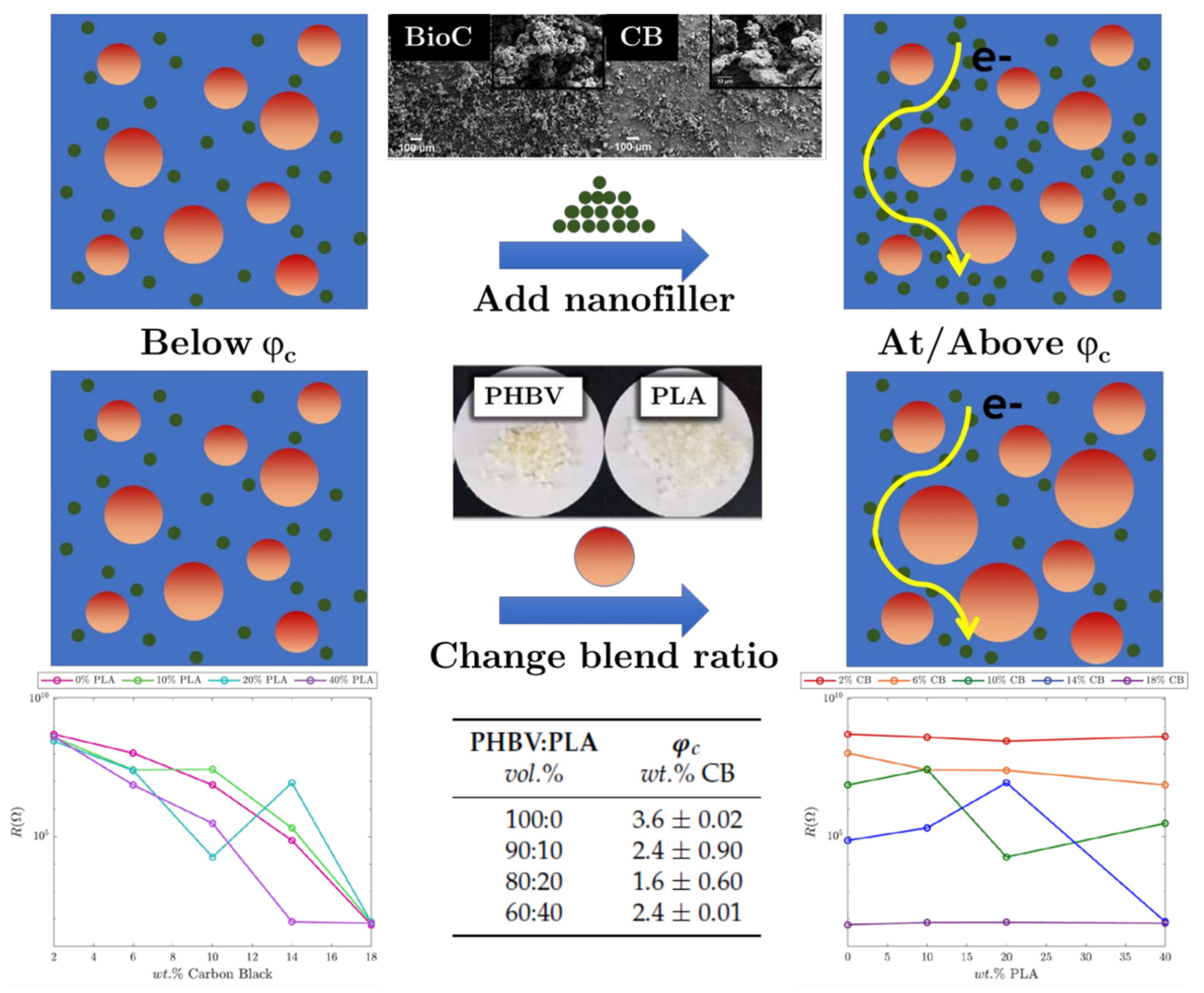
  24. Arroyo, J.; Ryan, C. Incorporation of carbon nanofillers tunes mechanical and electrical percolation in PHBV: PLA blends. Polymers 2018, 10, 1371. [Google Scholar] [CrossRef] [PubMed] [Green Version]
  25. Meincke, O.; Kaempfer, D.; Weickmann, H.; Friedrich, C.; Vathauer, M.; Warth, H. Mechanical properties and electrical conductivity of carbon-nanotube filled polyamide-6 and its blends with acrylonitrile/butadiene/styrene. Polymer 2004, 45, 739–748. [Google Scholar] [CrossRef]
  26. Gubbels, F.; Jérôme, R.; Vanlathem, E.; Deltour, R.; Blacher, S.; Brouers, F. Kinetic and thermodynamic control of the selective localization of carbon black at the interface of immiscible polymer blends. Chem. Mater. 1998, 10, 1227–1235. [Google Scholar] [CrossRef]
  27. Wu, S. Chain structure, phase morphology, and toughness relationships in polymers and blends. Polym. Eng. Sci. 1990, 30, 753–761. [Google Scholar] [CrossRef]
  28. Ghanbarian, B.; Cheng, P. Application of continuum percolation theory for modeling single-and two-phase characteristics of anisotropic carbon paper gas diffusion layers. Journal of Power Sources. 2016, 307, 613–623. [Google Scholar] [CrossRef]
  29. Noël, A.; Faucheu, J.; Chenal, J.-M.; Viricelle, J.-P.; Bourgeat-Lami, E. Electrical and mechanical percolation in graphene-latex nanocomposites. Polymer 2014, 55, 5140–5145. [Google Scholar] [CrossRef]
  30. Moore, C.; Newman, M.E. Epidemics and percolation in small-world networks. Phys. Rev. E 2000, 61, 5678. [Google Scholar] [CrossRef] [Green Version]
  31. Yang, X.; Liang, C.; Ma, T.; Guo, Y.; Kong, J.; Gu, J.; Chen, M.; Zhu, J. A review on thermally conductive polymeric composites: Classification, measurement, model and equations, mechanism and fabrication methods. Adv. Compos. Hybrid Mater. 2018, 1, 207–230. [Google Scholar] [CrossRef]
  32. Pan, L.; Ge, C.; Lu, L.; Wang, J. An oxygen permeability predictive model without geometric factors for immiscible polymer blended films based on fractal and percolation theory. Food Packag. Shelf Life 2019, 22, 100335. [Google Scholar] [CrossRef]
  33. Ouali, N.; Cavaillé, J.; Perez, J. Elastic, viscoelastic and plastic behavior of multiphase polymer blends. Plastics. Rubber Compos. Rubber Compos. Process. Appl. (Uk) 1991, 16, 55–60. [Google Scholar]
  34. Yi, Y.; Tawerghi, E. Geometric percolation thresholds of interpenetrating plates in three-dimensional space. Phys. Rev. E 2009, 79, 041134. [Google Scholar] [CrossRef] [PubMed] [Green Version]
  35. Mathew, M.; Schilling, T.; Oettel, M. Connectivity percolation in suspensions of hard platelets. Phys. Rev. E 2012, 85, 061407. [Google Scholar] [CrossRef] [PubMed] [Green Version]
  36. Ambrosetti, G.; Johner, N.; Grimaldi, C.; Danani, A.; Ryser, P. Percolative properties of hard oblate ellipsoids of revolution with a soft shell. Phys. Rev. E 2008, 78, 061126. [Google Scholar] [CrossRef] [PubMed] [Green Version]
  37. Ambrosetti, G.; Grimaldi, C.; Balberg, I.; Maeder, T.; Danani, A.; Ryser, P. Solution of the tunneling-percolation problem in the nanocomposite regime. Phys. Rev. B 2010, 81, 155434. [Google Scholar] [CrossRef] [Green Version]
  38. Otten, R.H.; van der Schoot, P. Connectedness percolation of elongated hard particles in an external field. Phys. Rev. Lett. 2012, 108, 088301. [Google Scholar] [CrossRef] [Green Version]
  39. Chatterjee, A.P. Percolation in polydisperse systems of aligned rods: A lattice-based analysis. J. Chem. Phys. 2014, 140, 204911. [Google Scholar] [CrossRef]
  40. Kale, S.; Sabet, F.A.; Jasiuk, I.; Ostoja-Starzewski, M. Effect of filler alignment on percolation in polymer nanocomposites using tunneling-percolation model. J. Appl. Phys. 2016, 120, 045105. [Google Scholar] [CrossRef]
  41. Khan, S.U.; Pothnis, J.R.; Kim, J.-K. Effects of carbon nanotube alignment on electrical and mechanical properties of epoxy nanocomposites. Compos. Part A: Appl. Sci. Manuf. 2013, 49, 26–34. [Google Scholar] [CrossRef]
  42. Jalal, M.; Moradi-Dastjerdi, R.; Bidram, M. Big data in nanocomposites: ONN approach and mesh-free method for functionally graded carbon nanotube-reinforced composites. J. Comput. Des. Eng. 2019, 6, 209–223. [Google Scholar] [CrossRef]
  43. Shi, D.L.; Feng, X.Q.; Huang, Y.Y.; Hwang, K.C.; Gao, H. The effect of nanotube waviness and agglomeration on the elastic property of carbon nanotube-reinforced composites. J. Eng. Mater. Technol. 2004, 126, 250–257. [Google Scholar] [CrossRef]
  44. Mitchell, C.A.; Bahr, J.L.; Arepalli, S.; Tour, J.M.; Krishnamoorti, R. Dispersion of functionalized carbon nanotubes in polystyrene. Macromolecules 2002, 35, 8825–8830. [Google Scholar] [CrossRef]
  45. Saini, P.; Sharma, B.; Singh, M.; Tandon, R.P.; Singh, S.P.; Mahapatro, A.K. Electrical Properties of Self Sustained Layer of Graphene Oxide and Polyvinylpyriodine Composite. Integr. Ferroelectr. 2019, 202, 197–203. [Google Scholar] [CrossRef]
  46. Stankovich, S.; Dikin, D.A.; Dommett, G.H.; Kohlhaas, K.M.; Zimney, E.J.; Stach, E.A.; Piner, R.D.; Nguyen, S.T.; Ruoff, R.S. Graphene-based composite materials. Nature 2006, 442, 282. [Google Scholar] [CrossRef] [PubMed]
  47. Nawaz, K.; Khan, U.; Ul-Haq, N.; May, P.; O’Neill, A.; Coleman, J.N. Observation of mechanical percolation in functionalized graphene oxide/elastomer composites. Carbon 2012, 50, 4489–4494. [Google Scholar] [CrossRef]
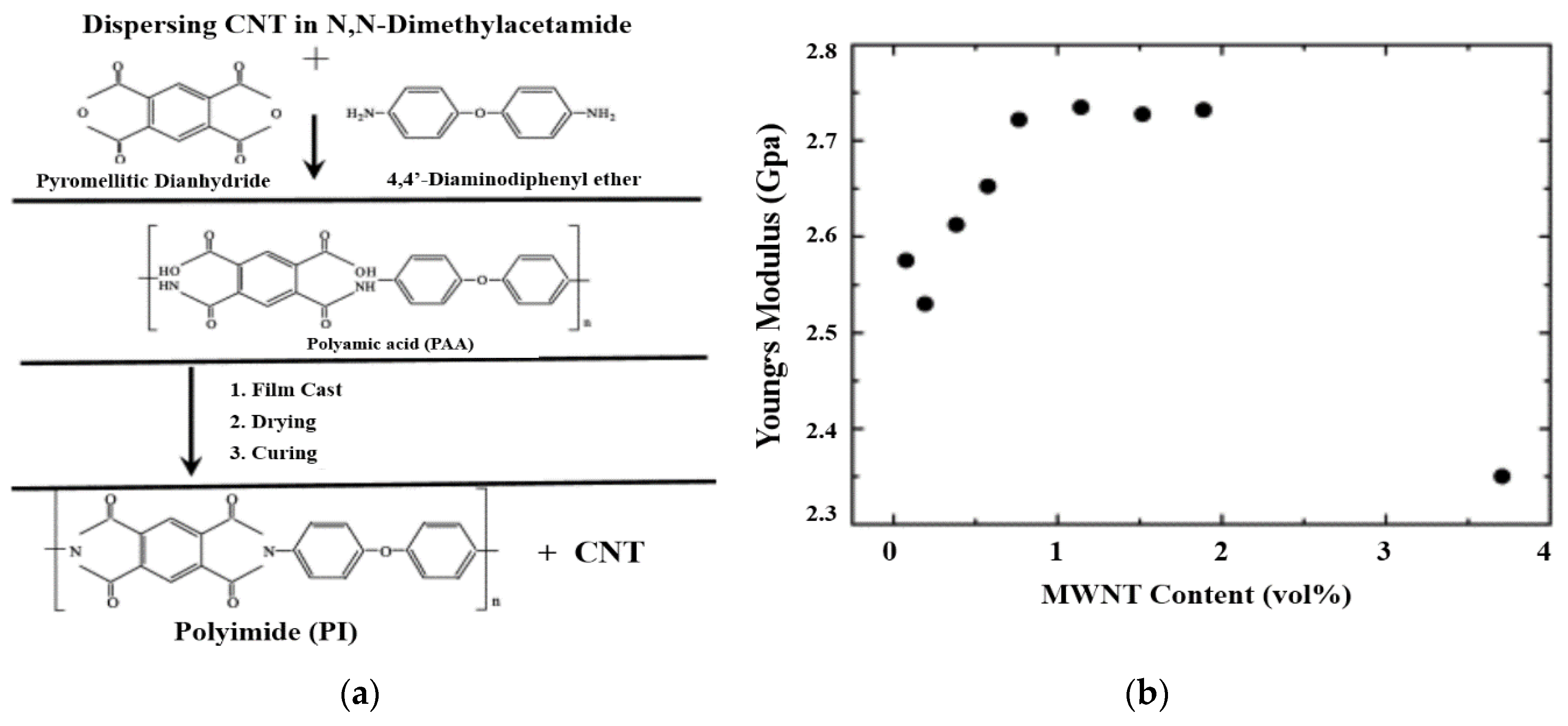
  48. Jiang, X.; Bin, Y.; Matsuo, M. Electrical and mechanical properties of polyimide–carbon nanotubes composites fabricated by in situ polymerization. Polymer 2005, 46, 7418–7424. [Google Scholar] [CrossRef]
  49. Shaffer, M.S.; Windle, A.H. Fabrication and characterization of carbon nanotube/poly (vinyl alcohol) composites. Adv. Mater. 1999, 11, 937–941. [Google Scholar] [CrossRef]
  50. Oskouyi, A.; Sundararaj, U.; Mertiny, P. Tunneling conductivity and piezoresistivity of composites containing randomly dispersed conductive nano-platelets. Materials 2014, 7, 2501–2521. [Google Scholar] [CrossRef]
  51. Hicks, J.; Behnam, A.; Ural, A. A computational study of tunneling-percolation electrical transport in graphene-based nanocomposites. Appl. Phys. Lett. 2009, 95, 213103. [Google Scholar] [CrossRef] [Green Version]
  52. Lemoult, G.; Shi, L.; Avila, K.; Jalikop, S.V.; Avila, M.; Hof, B. Directed percolation phase transition to sustained turbulence in Couette flow. Nat. Phys. 2016, 12, 254. [Google Scholar] [CrossRef]
  53. Privman, V.; Švrakić, N.M. Directed Models of Polymers, Interfaces, and Clusters: Scaling and Finite-Size Properties; Springer: Berlin, Germany, 1989. [Google Scholar]
  54. Knežević, D.; Knežević, M. Semi-directed percolation in two dimensions. Physica A Stat. Mech. Appl. 2016, 444, 560–565. [Google Scholar]
  55. Grimaldi, C.; Maeder, T.; Ryser, P.; Strässler, S. Piezoresistivity and conductance anisotropy of tunneling-percolating systems. Phys. Rev. B 2003, 67, 014205. [Google Scholar] [CrossRef] [Green Version]
  56. Silva, J.; Ribeiro, S.; Lanceros-Mendez, S.; Simões, R. The influence of matrix mediated hopping conductivity, filler concentration, aspect ratio and orientation on the electrical response of carbon nanotube/polymer nanocomposites. Compos. Sci. Technol. 2011, 71, 643–646. [Google Scholar] [CrossRef] [Green Version]
  57. White, S.I.; DiDonna, B.A.; Mu, M.; Lubensky, T.C.; Winey, K.I. Simulations and electrical conductivity of percolated networks of finite rods with various degrees of axial alignment. Phys. Rev. B 2009, 79, 024301. [Google Scholar] [CrossRef] [Green Version]
  58. Wu, K.; Xue, Y.; Yang, W.; Chai, S.; Chen, F.; Fu, Q. Largely enhanced thermal and electrical conductivity via constructing double percolated filler network in polypropylene/expanded graphite–multi-wall carbon nanotubes ternary composites. Compos. Sci. Technol. 2016, 130, 28–35. [Google Scholar] [CrossRef]
  59. Wie, J.; Kim, J. Thermal Conductivity Enhancement Derived from Poly (Methyl Methacrylate)-Grafted Carbon Nanotubes in Poly (Methyl Methacrylate)/Polystyrene Blends. Polymers 2019, 11, 1347. [Google Scholar] [CrossRef] [Green Version]
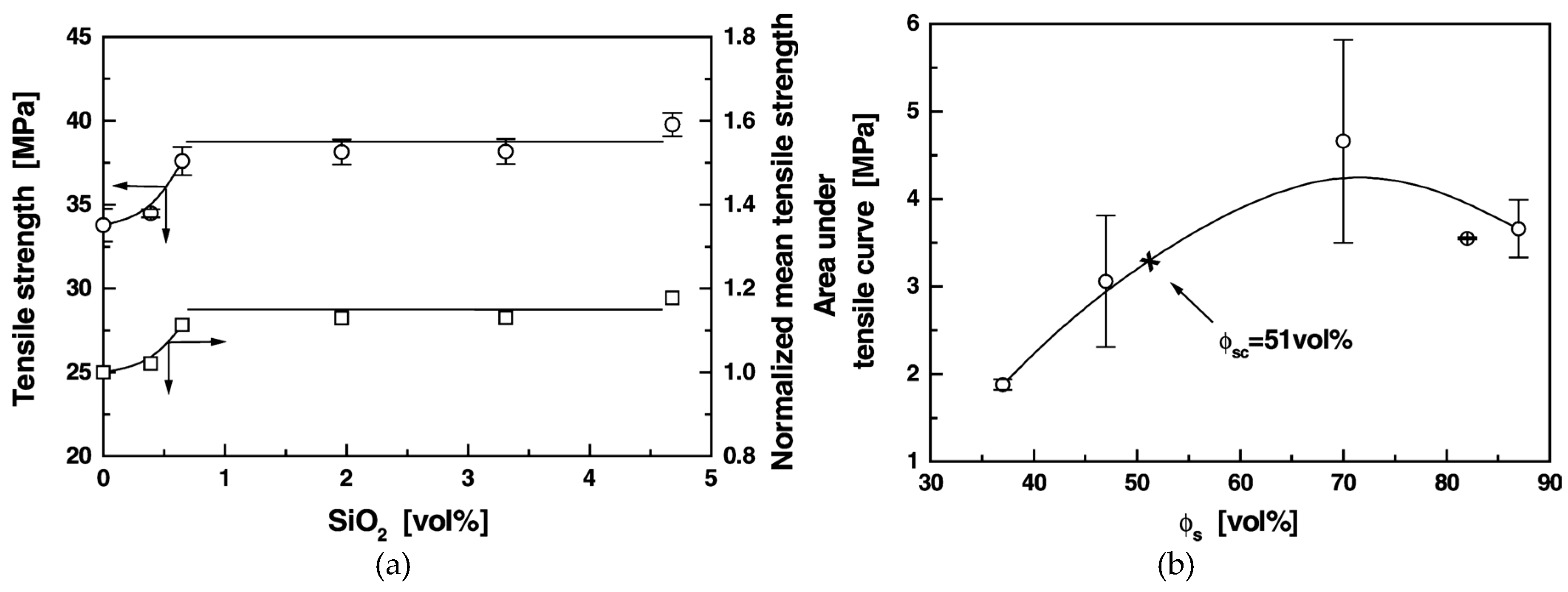
  60. Rong, M.Z.; Zhang, M.Q.; Zheng, Y.X.; Zeng, H.M.; Friedrich, K. Improvement of tensile properties of nano-SiO2/PP composites in relation to percolation mechanism. Polymer 2001, 42, 3301–3304. [Google Scholar] [CrossRef]
  61. Nikfar, N.; Zare, Y.; Rhee, K.Y. Dependence of mechanical performances of polymer/carbon nanotubes nanocomposites on percolation threshold. Phys. B Condens. Matter 2018, 533, 69–75. [Google Scholar] [CrossRef]
  62. Halpin, J.C. Effects of Environmental Factors on Composite Materials; Air Force Materials Lab Wright-Patterson AFB OH: Wright-Patterson AFB, OH, USA, 1969.
  63. Sun, L.-H.; Ounaies, Z.; Gao, X.-L.; Whalen, C.A.; Yang, Z.-G. Preparation, characterization, and modeling of carbon nanofiber/epoxy nanocomposites. J. Nanomater. 2011, 2011. [Google Scholar] [CrossRef] [Green Version]
  64. Zare, Y.; Rhee, K.Y.; Park, S.-J. A developed equation for electrical conductivity of polymer carbon nanotubes (CNT) nanocomposites based on Halpin-Tsai model. Results Phys. 2019, 14, 102406. [Google Scholar] [CrossRef]
  65. Wu, D.; Wu, L.; Zhou, W.; Sun, Y.; Zhang, M. Relations between the aspect ratio of carbon nanotubes and the formation of percolation networks in biodegradable polylactide/carbon nanotube composites. J. Polym. Sci. Part B Polym. Phys. 2010, 48, 479–489. [Google Scholar] [CrossRef]
  66. Yeh, M.-K.; Tai, N.-H.; Liu, J.-H. Mechanical behavior of phenolic-based composites reinforced with multi-walled carbon nanotubes. Carbon 2006, 44, 1–9. [Google Scholar] [CrossRef]
  67. Liang, J.Z. Toughening and reinforcing in rigid inorganic particulate filled poly (propylene): A review. J. Appl. Polym. Sci. 2002, 83, 1547–1555. [Google Scholar] [CrossRef]
  68. Liang, J.; Li, R. Mechanical properties and morphology of glass bead–filled polypropylene composites. Polym. Compos. 1998, 19, 698–703. [Google Scholar] [CrossRef]
  69. Baxter, S.C.; Robinson, C.T. Pseudo-percolation: Critical volume fractions and mechanical percolation in polymer nanocomposites. Compos. Sci. Technol. 2011, 71, 1273–1279. [Google Scholar] [CrossRef]
  70. Snipes, J.; Robinson, C.; Baxter, S. Effects of scale and interface on the three-dimensional micromechanics of polymer nanocomposites. J. Compos. Mater. 2011, 45, 2537–2546. [Google Scholar] [CrossRef]
  71. Fralick, B.S.; Gatzke, E.P.; Baxter, S.C. Three-dimensional evolution of mechanical percolation in nanocomposites with random microstructures. Probabilistic Eng. Mech. 2012, 30, 1–8. [Google Scholar] [CrossRef] [Green Version]
  72. Xu, W.; Wu, F.; Jiao, Y.; Liu, M. A general micromechanical framework of effective moduli for the design of nonspherical nano-and micro-particle reinforced composites with interface properties. Mater. Des. 2017, 127, 162–172. [Google Scholar] [CrossRef]
  73. Bernard, O.; Ulm, F.-J.; Lemarchand, E. A multiscale micromechanics-hydration model for the early-age elastic properties of cement-based materials. Cem. Concr. Res. 2003, 33, 1293–1309. [Google Scholar] [CrossRef]
  74. Xu, W.; Ma, H.; Ji, S.; Chen, H. Analytical effective elastic properties of particulate composites with soft interfaces around anisotropic particles. Compos. Sci. Technol. 2016, 129, 10–18. [Google Scholar] [CrossRef]
  75. Underwood, B.S.; Kim, Y.R. A four phase micro-mechanical model for asphalt mastic modulus. Mech. Mater. 2014, 75, 13–33. [Google Scholar] [CrossRef]
  76. Ngabonziza, Y.; Li, J.; Barry, C. Electrical conductivity and mechanical properties of multiwalled carbon nanotube-reinforced polypropylene nanocomposites. Acta Mech. 2011, 220, 289–298. [Google Scholar] [CrossRef]
  77. Taya, M. Micromechanics modeling of smart composites. Compos. Part A Appl. Sci. Manufac. 1999, 30, 531–536. [Google Scholar] [CrossRef]
  78. Loos, M.R.; Manas-Zloczower, I. Reinforcement efficiency of carbon nanotubes–myth and reality. Macromol. Theory Simul. 2012, 21, 130–137. [Google Scholar] [CrossRef]
  79. García-Macías, E.; D’Alessandro, A.; Castro-Triguero, R.; Pérez-Mira, D.; Ubertini, F. Micromechanics modeling of the uniaxial strain-sensing property of carbon nanotube cement-matrix composites for SHM applications. Compos. Struct. 2017, 163, 195–215. [Google Scholar] [CrossRef]
  80. Feng, C.; Jiang, L. Micromechanics modeling of the electrical conductivity of carbon nanotube (CNT)–polymer nanocomposites. Compos. Part A Appl. Sci. Manufac. 2013, 47, 143–149. [Google Scholar] [CrossRef]
  81. Jarali, C.S.; Patil, S.F.; Pilli, S.C. Hygro-thermo-electric properties of carbon nanotube epoxy nanocomposites with agglomeration effects. Mech. Adv. Mater. Struc. 2015, 22, 428–439. [Google Scholar] [CrossRef]
  82. Kim, S.Y.; Noh, Y.J.; Yu, J. Prediction and experimental validation of electrical percolation by applying a modified micromechanics model considering multiple heterogeneous inclusions. Compos. Sci. Technol. 2015, 106, 156–162. [Google Scholar] [CrossRef]
  83. Sun, B.; Wang, W.; He, Z.; Zhang, M.; Kong, F.; Sain, M. Biopolymer Substrates in Buccal Drug Delivery: Current Status and Future Trend. Curr. Med. Chem. 2019. [Google Scholar] [CrossRef]
  84. Sun, B.; Wang, W.; He, Z.; Zhang, M.; Kong, F.; Sain, M.; Ni, Y. Improvement of Stability of Tea Polyphenols: A Review. Curr. Pharm. Des. 2018, 24, 3410–3423. [Google Scholar] [CrossRef]
  85. Sun, B.; Zhang, M.; Ni, Y. Use of sulfated cellulose nanocrystals towards stability enhancement of gelatin-encapsulated tea polyphenols. Cellulose 2018, 25, 5157–5173. [Google Scholar] [CrossRef]
  86. Sun, B.; Zhang, M.; He, Z.; Zheng, L.; Shen, J.; Ni, Y. Towards greener and more sustainable cellulose-based hand sanitizer products. J. Bioresour. Bioprod. 2017, 2, 56–60. [Google Scholar]
  87. Sun, B.; Zhang, M.; Shen, J.; He, Z.; Fatehi, P.; Ni, Y. Applications of cellulose-based materials in sustained drug delivery systems. Curr Med Chem. 2019, 26, 2485–2501. [Google Scholar] [CrossRef] [PubMed]
  88. Sun, B.; Hou, Q.; He, Z.; Liu, Z.; Ni, Y. Cellulose nanocrystals (CNC) as carriers for a spirooxazine dye and its effect on photochromic efficiency. Carbohydr. Polym. 2014, 111, 419–424. [Google Scholar] [CrossRef] [PubMed]
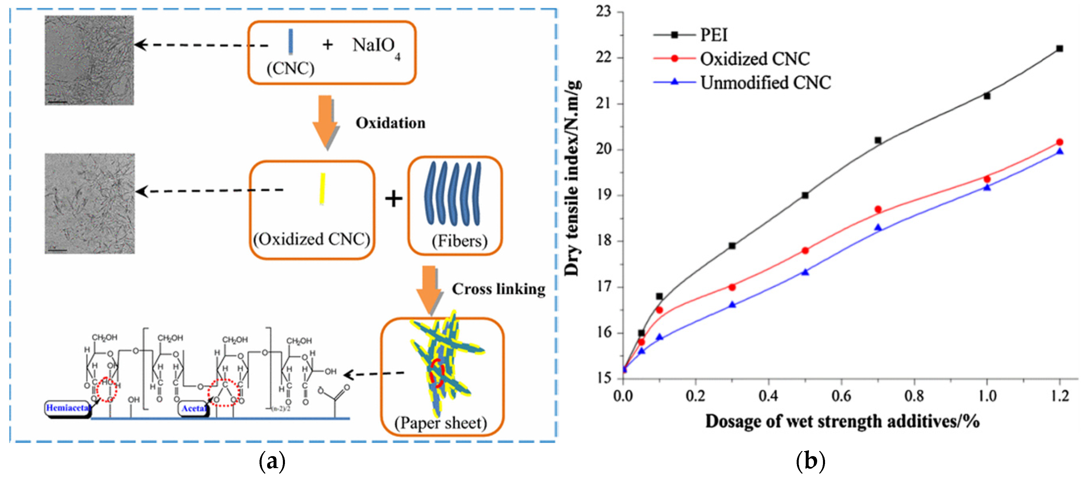
  89. Sun, B.; Hou, Q.; Liu, Z.; Ni, Y. Sodium periodate oxidation of cellulose nanocrystal and its application as a paper wet strength additive. Cellulose 2015, 22, 1135–1146. [Google Scholar] [CrossRef]
  90. Loos, M.; Manas-Zloczower, I. Micromechanical models for carbon nanotube and cellulose nanowhisker reinforced composites. Polym. Eng. Sci. 2013, 53, 882–887. [Google Scholar] [CrossRef]
Figure 1. Chemical modification of CNT or graphene via four typical schemes [12].
Coatings 10 00193 g001
Figure 2. SEM images of carbonized bamboo (a), and bamboo-derived granular renewable carbon with magnification of ×100 (b), ×1500 (c) and ×5000 (d) [14].
Coatings 10 00193 g002
Figure 3. Mechanism for granular carbon in enriching the hydrogen-utilizing methanogens, Geobacter and other methanogens capable of direct interspecies electron transfer, to accelerate the methane generation and sludge consumption [16].
Coatings 10 00193 g003
Figure 4. SEM images of a typical powdered renewable carbon (a,b) and transmission electron microscopy (TEM) images corresponding to its pore structure (c,d). Insets in (c,d) show the FFT pattern which confirms the amorphous structure of renewable carbon [17].
Coatings 10 00193 g004
Figure 5. Rod-like CNT/graphene doped composites with anticipated enhanced properties [12].
Coatings 10 00193 g005
Figure 6. Incorporation of CNT into PHBV: PLA blends and their corresponding properties [24].
Coatings 10 00193 g006
Figure 7. Schematic diagram of site percolation (a) and probability of percolation (b) [32].
Coatings 10 00193 g007
Figure 8. Schematic of finite and infinite clusters with a percolation concept (a), and series/parallel springs model for mechanical response of the percolated composite (b) [29].
Coatings 10 00193 g008
Figure 9. Three fundamental geometries of plates (ac), and computer realization of one hundred circular plates in 3D space (d) [34].
Coatings 10 00193 g009
Figure 10. Scaled particle concentration cp = πDL2ρp/4 at the percolation threshold as a function of the dimensionless field strength, βK. Where D refers to the diameter (particles were presumed mutually impenetrable rigid cylinders), L refers to the length and ρp is percolation threshold). Solid lines— connectivity percolation; dashed curves—contact-volume approach for λ/D = 0.3 (top), 0.6 (middle) and 1 (bottom). The percolating network only existed in the enclosed areas. The shaded area is the region of coexisting isotropic (paranematic) and nematic phases. Inset (a): calculated percolation thresholds scaled to the zero-field value c0p. Inset (b): order parameter S2 with, from steepest to flattest, λ/D = 0.3, 0.6 and 1. The dots indicate the largest value of |βK| that allows for a percolation threshold [38].
Coatings 10 00193 g010
Figure 11. Alignment of MWCNT in epoxy nanocomposites (a), and Raman spectra of aligned MWCNT/epoxy composites, showing different G-band peak intensities as the change of the direction of applied polarized light against the CNT alignment (b) [41].
Coatings 10 00193 g011
Figure 12. Quasi-static fracture surface morphologies of neat epoxy (a), 0.3 wt% of randomly distributed MWCNT-nanocomposites (b), 0.3 wt% of aligned MWCNT-nanocomposites (c and d), crack bridged by aligned single and bundle MWCNT (e) and after MWCNT pull-out (f) [41].
Coatings 10 00193 g012
Figure 13. Schematic representation of nanocomposite cylinder with functionally graded (FG) distribution along with CNT coordinates (A), and representative volume element (RVE) with Eshelby cluster model of agglomerated CNT (B) [42].
Coatings 10 00193 g013
Figure 14. Polymeric composite which consists of both continuous carbon nanotube (CNT) and chemically modified CNT or graphene carbon as matrix modifiers (A), and loss modulus and electrical conductivity with respect to interfacial volume fraction in CNT or graphene carbon nanocomposites (B) [12].
Coatings 10 00193 g014aCoatings 10 00193 g014b
Figure 15. The preparation procedure of polyimide composite film with MWNT carbon (a), and Young’s modulus of PI-MWNT composites films against the MWNT content (b) [48].
Coatings 10 00193 g015
Figure 16. SEM pattern of the cross-section of PI-MWNT (MWNT = 1.14 vol%) composite film (a), and the enlargement of its selected area (b) [48].
Coatings 10 00193 g016
Figure 17. A semi-directed site percolation cluster on the square lattice, containing N = 17 sites (filled circles) on a strip of width n = 5, due to periodic boundary conditions the sites denoted by 1 and 1′, are identified. The strip is infinite along the horizontal axis (the preferred direction). In contrast to the case of fully directed percolation, vertical lines of the lattice are not directed, which means that the set of all semi-directed percolation clusters includes the set of all possible fully directed clusters [54].
Coatings 10 00193 g017
Figure 18. Increased alignment of prolate ellipsoids at various nematic order parameter <S> of (a) 0, (b) 0.25, (c) 0.5 and (d) 0.9. The green fillers are percolating clusters, while red fillers are other isolated clusters. The m value is equal to mmin (m≥mmin=3〈S〉/(1−〈S〉)) [40].
Coatings 10 00193 g018
Figure 19. Schematic diagram of dual percolation network constructed by the cooperation of EG and MWCNT in the matrix. Follow the direction of the arrows, MWCNT content inside of the PP/EG-MWCNT ternary composites is increasing [58].
Coatings 10 00193 g019
Figure 20. Infrared camera images of samples that represent the effect of dual percolation [59].
Coatings 10 00193 g020
Figure 21. Tensile strength of SiO2-g-PS/PP composites as a function of the volume fraction of SiO2 (a), and area under the tensile stress–strain curve of SiO2-g-PS/PP composites as a function of the stress volume fraction of φs (b) [60].
Coatings 10 00193 g021
Figure 22. Interfacial debonding model [67].
Coatings 10 00193 g022
Figure 23. Representative microscale volume element (RVE) containing straight carbon fillers [79].
Coatings 10 00193 g023
Figure 24. Sketch of volume element (RVE) with ellipsoidal bundles of carbon fillers [79].
Coatings 10 00193 g024
Figure 25. Molecular structure of nanocellulose macromolecule (a), TEM image of nanocellulose (b) and nanocellulose-SO compounds (c) [9,87,88].
Coatings 10 00193 g025
Figure 26. Swelling kinetics (Qt) and linear plotting (t/Qt) of BE film and co-blended film at different submerse time (t) (tests were conducted inside of distilled water at room temperature) (A), gas diffusion dynamic as the relative humidity (RH) increases (B), and effect of relative humidity (RH, %) on the gas permeability and gas selectivity of the BE film (Bottom Side, test was conducted at the temperature of 25 °C) (C) [9].
Coatings 10 00193 g026
Figure 27. Interaction between oxidized nanocellulose and pulp fibrils (a), and tensile strength of composites made from unmodified nanocellulose-fibrils, modified nanocellulose-fibrils and PEI-fibrils (b) [89].
Coatings 10 00193 g027
Table 1. Estimated percolation points (ηc) for different geometries in 3D space [34].
GeometryCircular PlatesSquare PlatesTriangular Plates
ηc0.96140.86470.7295
Error± 0.0005±0.0006±0.0006

