Article

Synthesis and Physical Properties of Antiperovskite CuNFe3 Thin Films via Solution Processing for Room Temperature Soft-Magnets

1
College of Chemistry and Materials Engineering, Anhui Science and Technology University, Fengyang 233100, China
2
College of Electrical and Electronic Engineering, Anhui Science and Technology University, Fengyang 233100, China
3
Key Laboratory of Materials Physics, Institute of Solid State Physics, University of Chinese Academy of Sciences, Hefei 230031, China
*
Author to whom correspondence should be addressed.
Coatings 2020, 10(3), 270; https://doi.org/10.3390/coatings10030270
Submission received: 18 February 2020 / Revised: 7 March 2020 / Accepted: 13 March 2020 / Published: 13 March 2020
(This article belongs to the Section Thin Films)

Abstract

:
Antiperovskite CuNFe3 (CNF) thin films have been successfully prepared by chemical solution deposition (CSD) for the first time. They are versatile in many applications as an iron-based nitride. The preparation of pure CNF thin films is a challenging work for the complexity of the phase diagram. Herein, the CNF thin films are phase-pure and polycrystalline. Annealing temperature effects on the microstructures and physical properties were investigated, showing that the CNF thin films are metallic and can be considered as a candidate for room temperature soft-magnets with a large saturated magnetization (Ms) and a low coercive field (Hc). At high temperatures, the electrical transport behavior of CNF thin films presents a low temperature coefficient of resistivity (TCR) value, while the electron–electron interaction is prominent at low temperatures. The reported solution methods of CNF thin films will enable extensive fundamental investigation of the microstructures and properties as well as provide an effective route to prepare other antiperovskite transition-metal nitride thin films.

Graphical Abstract

1. Introduction

Transition-metal nitrides are widely known for their interesting physical properties and potential applications with superconductivity for the electronic device, unusual magnetic properties for the high-density recording materials, excellent electrochemical characteristics for supercapacitors, and high mechanical strength for cutting tools [1,2,3,4,5]. Among the ternary metal nitrides, one of the most widely studied nitrides is a compound with antiperovskite structure. Its chemical formula is AXM3 (A = Cu, Ag, Ga, Sn, Al, Zn, Ge, In, etc.; X = N; and M = Sc, Ti, V, Cr, Mn, Fe, Co, Ni, etc.). The A atoms are located at the corner position of the crystal lattice, the six M atoms at the face-center position, and the non-metal atom X at the body-center position constitutes the XM6 regular octahedron.
Mn-, Ni-, and Co-based nitrides have been extensively investigated by both experimental and theoretical methods [6,7,8,9,10]. However, for the iron-based metal nitrides, their magnetic properties, electrical transport, and other specific physical properties have rarely been reported. Initially, researchers did not pay much attention to them, and only studied the structure of iron nitride using X-ray technology, while others investigated the magnetism of iron nitrides experimentally. Since the 1950s, owing to their excellent ferromagnetic, high spin polarization, good oxidation resistance, and high mechanical properties, iron-based nitride materials have been widely used in magnetic recording and spintronic devices [11]. Due to the complexity of the Fe-N phase diagram including α-Fe(N) (face centered cubic), FeN (NaCl type), ξ-Fe2N (hexagonal), ε-Fe3N (hexagonal), γ′-Fe4N (antiperovskite), α′-Fe8N (tetragonal), α″-Fe16N2 (tetragonal), etc., it is difficult to obtain the iron-based antiperovskite of pure phase. As a typical case, γ′-Fe4N, with a large Ms and a low Hc at room temperature, has attracted considerable interest as one candidate for soft-magnets [12]. Room temperature soft-magnets are materials that quickly respond to changes in external magnetic fields at room temperature and can obtain high magnetization with low loss. They have important applications in power transformers, high frequency inductors, electric motor rotors, flux gate magnetometers, and high-density recorders [13,14,15,16]. There are two different types of Fe atoms in the γ′-Fe4N unit cell. Fe (I) located at the corner position does not have the nearest neighbor N atom, and the interaction between Fe atom and N atom is weak. As for the saturation moment, the value is 2.98 μB/atom for Fe (I) at room temperature. Fe (II) located at the face center with the two nearest neighbor N atom has a relatively small magnetic moment of 2.01 μB/atom [17].
To further investigate the physical properties and potential applications of iron-based antiperovskite materials, the preparation of single crystals and high-quality thin films has become an effective route. Many attempts and efforts have been made, such as using physical methods of RF magnetron sputtering, molecular beam epitaxy (MBE), and pulse laser deposition (PLD) to prepare nitride thin films. RF magnetron sputtering is a physical vapor deposition (PVD) technique, which “sputters” or “removes” material from a target source and deposits this ejected material onto a substrate support. MBE is an industry standard tool for the growth of thin films. This technique offers excellent stoichiometric compositional control and the ability to grow compositionally graded thin films. PLD is a thin film growth technique, whereby a high-power pulsed laser beam is focused on a target of the material that is to be deposited onto a substrate [18]. However, these physical methods have various drawbacks when depositing thin films. For instance, the major shortfall of stoichiometry control in RF magnetron sputtering occurs for dopant-level film constituents [19]. The limited length scale of the film thickness uniformity makes PLD less suited to meeting the surface flatness and large area uniformity criteria required for complex thin films. The MBE technique is also limited by low throughput/yield and is an expensive technique to use and sustain [18]. As a result, the CSD method is an excellent technique to grow thin films of complex chemical compositions, which has the advantages of low processing temperature, the high degree of compositional control, low equipment cost, high deposition rates, and uniform deposition over large area substrates, and has been widely used in recent years [2,9,20,21].
Recently, we reported that CuNNi3 and CuNCo3 antiperovskite thin films were successfully prepared by CSD method [2,9]. Herein, the preparation of antiperovskite CNF thin films on silicon substrates by CSD is reported for the first time. The derived CNF thin films show a cubic lattice constant about 3.807 Å, which is similar to that of the Fe4N thin film (a = 3.790 Å), indicating the near stoichiometric of nitrogen in the CNF thin films [17]. The results show that the thus-derived CNF thin films are phase-pure and polycrystalline. Annealing temperature effects on the microstructures and physical properties are investigated, showing that the CNF thin films are metallic and can be considered as a new candidate for room temperature soft-magnets with a large Ms and a low Hc. The results will provide an effective route to deposit iron-based antiperovskite thin films as well as provide a useful prototype to investigate other antiperovskite thin films by solution methods.

2. Materials and Methods

CNF thin films were prepared by CSD. Cupric nitrate (Cu(NO3)3·3H2O) and ferric nitrate (Fe(NO3)3·9H2O) used as the precursor materials were dissolved into 2-methoxyethanol (2-MOE) to prepare the coating solution. The concentration of the metal ionic solution was 0.4 mol/L. Then, the solution was allowed to stand for 12 h waiting for deposition. The spin-coating deposition technique was used. The substrates used for depositing thin films are Si (001) substrates. Prior to deposition of the films, to increase the cleanliness and acceptable wetting of the substrate, all substrates were ultrasonically cleaned in acetone, absolute ethanol, and distilled water for 5 min in sequence, and finally cleaned with plasma cleaner for 10 min. During the spin-coating processing, the deposition temperature was 40 °C, the rotational speed was 5000 rpm, and the time was 10 s. Then, the gel film was baked for 2 min at 150 °C, and pyrolyzed in air for 10 min at 350 °C. The term pyrolysis is mainly used to describe the decomposition of the organic matrix. To increase the thickness, the above processes were repeated 8 times. Finally, the obtained thin films were annealed in air at 850 °C for 2 h, and then annealed at a pressure of 1 atm for 2 h in a flowing ammonia atmosphere at different annealing temperatures. During the pyrolysis process and annealing at 850 °C for 2 h under air, cupric nitrate and ferric nitrate are decomposed and form the metal oxide Cu0.75Fe2.25O4 (cubic, PDF Card No. 01-073-2316) [22]. Then, the Cu0.75Fe2.25O4 is converted into CuNFe3 phase by annealing process at different temperature under flowing ammonia atmosphere. The post-annealing treatment can be used to initiate crystallization, optimize microstructure, and improve thin film densification. To simplify of description, the CNF thin films annealed at 700, 800, and 900 °C are labeled as CNF/700, CNF/800, and CNF/900, respectively. The experimental process flow chart of the derived thin film preparation is shown in Figure 1.
The crystal quality and phase composition of the CNF thin films were analyzed by small angle X-ray diffraction at room temperature using monochrome Cu-Kα ray (SAXRD, X’Pert PRO, PANalytical, Almelo, The Netherlands). The surface morphology and thickness of the films were measured with a field emission scanning electron microscopy (FE-SEM, Sirion 200, FEI, Hillsboro, OR, USA). The microstructures were further analyzed by high-resolution transmission electron microscopy (HRTEM, JEM-2010, JEOL Ltd., Tokyo, Japan). The chemical states of copper, nitrogen, and iron were analyzed by X-ray photoelectron spectroscopy (XPS, ESCALAB250, Thermo, Waltham, MA, USA). The magnetization measurements were carried out on the superconducting quantum interface device (SQUID, Quantum Design, San Diego, CA, USA). The electrical transport properties were investigated on the physical properties measurement system (PPMS, Quantum Design, San Diego, CA, USA) using the standard four-point probe technique.

3. Results

3.1. Structural and Surface Morphology Studies

The SAXRD patterns of CNF thin films with different annealing temperatures at room temperature are shown in Figure 2. The results show that only CNF (111), (002), and (022) diffraction peaks can be observed, and there are no undesirable phases such as Fe, FeN, Fe2N, Fe3N, Fe8N, Fe16N2, Cu, Cu-N, Cu-O, Fe-O, etc. All films are single-phase and have no detectable impurities, which indicates that the annealing temperature range of 700–900 °C can be used for preparing CNF thin films by CSD method. The XRD patterns can be indexed by the space group of Pm-3m (PDF Card No. 01-086-0231) and the corresponding crystal structure is shown in the left inset of Figure 2. The derived thin films are randomly oriented and have a polycrystalline structure. The polycrystalline film is due to the homogeneous nucleation in the bulk thin film of CNF. A large thermal expansion coefficient difference and lattice mismatch will increase the interfacial energy between the CNF thin film and the silicon substrate, which will lead to the homogeneous nucleation in most of the bulk thin film, resulting in the formation of polycrystalline CNF thin films [23,24,25]. With the increase of annealing temperature, the intensity of the CNF diffraction peaks is enhanced, suggesting the improved crystalline quality.
The lattice constant of CNF thin film was calculated by Bragg formula (2dsinθ = nλ) and the formula between the interplanar spacing d and the lattice constant a of the cubic system, d = a/(h2 + k2 + l2)1/2 (h, k and l are the Miller indices), which uses the positions of CNF (111), (002), and (022) peaks. The final lattice constant’s value is the average value of the three abovementioned results. By analogy, the lattice constants of the other two samples can be obtained. For the derived CNF thin films, the lattice constants were calculated as 3.792, 3.799 and 3.807 Å for CNF/700, CNF/800, and CNF/900, respectively, as shown in the right inset of Figure 2. The slight enhancement of lattice constant with annealing temperature is attributed to the enhanced ammonization. In addition, the lattice constants of CNF thin films are larger than the previous theoretical result (a = 3.789 Å) [26] and experimental result (a = 3.790 Å) [17] about Fe4N, indicating the nearly stoichiometric of the derived CNF thin film. The calculation results reported previously show that the lattice constant of Fe4N decreases with the increase of nitrogen vacancies [27]. As mentioned above, copper doping facilitates the entry of nitrogen into the lattice, which can be interpreted by atomic electronegativity. Generally, the greater is the electronegativity difference between the atoms, the weaker is the affinity of the atoms, and vice versa. From the electronegativity differences among iron, copper, and nitrogen, it can be concluded that the affinity between iron and nitrogen is weaker than that between copper and nitrogen [28]. Consequently, compared with iron atom, copper atom will be combined with more nitrogen atoms, resulting in a higher nitrogen content in CNF than in Fe4N.
The surface FE-SEM results of CNF thin films with different annealing temperatures are shown in Figure 3a–c. These thin films exhibit relatively uniform and smooth surfaces. To get the average grain size, hundreds of grains were inspected by an image analyzer. In the corresponding FE-SEM results, the histograms show the grain size distribution of the derived all CNF thin films. The average grain sizes of CNF/700, CNF/800, and CNF/900 films were 75, 100, and 114 nm, respectively. As the annealing temperature increases, the grain size increases, which may be due to the increase rate of grain growth. As the mobility of grain boundaries and the rate of grain growth are strongly temperature-dependent, at lower annealing temperature, atoms diffusion along and across grain boundaries will be more hindered during the process of grain growth [29]. In addition, as the annealing temperature increases, the grain boundaries can be observed more clearly, further indicating the improved crystalline quality. Grain boundary plays an important role in the determination of the electrical transport properties. The increase of the grain size leads to the decrease of the grain boundary amounts, which will result in the decrease of resistivity, as described in detail below. As measured by cross-sectional FE-SEM, the thickness of the obtained film is 130 nm, as shown in Figure 3d. Since the derived thin films at different annealing temperatures were prepared under the same experimental conditions before the post-annealing process, the thicknesses of the all derived thin films are uniform, i.e., 130 nm. Obviously, an amorphous SiO2 layer can be observed from the figure. Additionally, the clean interface between the CNF thin film and the SiO2 layer indicates that there are no chemical reactions near the interface.
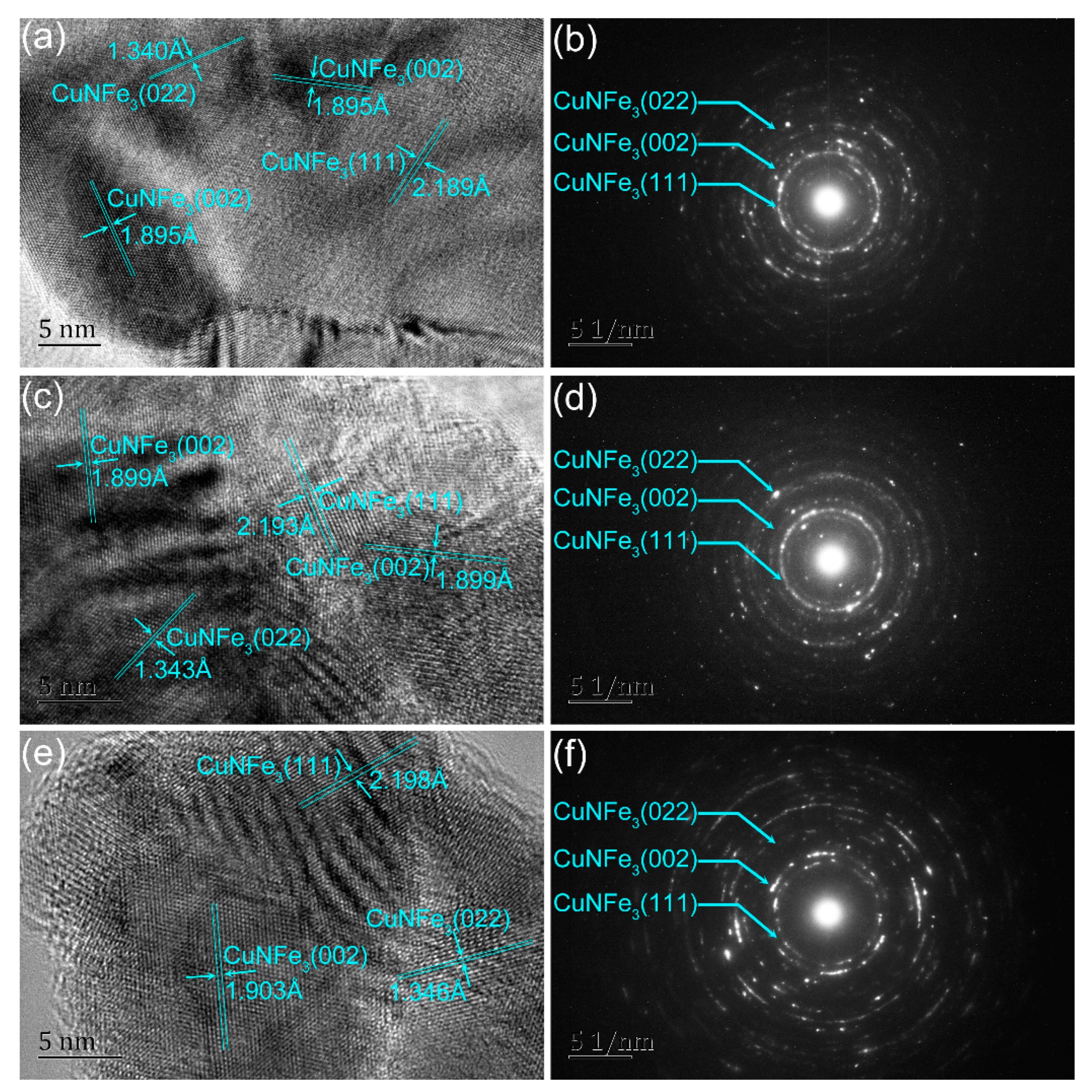
To further investigate the interplanar spacing and crystal quality of the CNF thin films with different annealing temperatures, HRTEM measurements were performed with the accelerating voltage of 200 kV. The surface HRTEM results are shown in Figure 4a,c,e. It can be seen that the grain boundaries of the derived CNF thin films are fuzzy and the grains are randomly oriented, indicating that the CNF thin films are polycrystalline. Moreover, the interplanar spacing d, as indexed, can be attributed to CNF (111), (002), and (022) planes. With the increasing annealing temperature, the derived d spacings increase gradually and the surface lattice stripes can be observed more clearly, confirming the XRD measurements. The selected area electron diffraction (SAED) patterns of CNF/700, CNF/800, and CNF/900 films are shown as diffraction rings in Figure 4b,d,f, respectively. The main diffractive rings from the center to the edge are (111), (002), and (022), which also shows the polycrystalline properties. However, there are additional diffraction pots along with the main phase in the SAED patterns of the derived thin films, which may not be seen in the XRD image. For these undesirable phases, owing to the lower annealing temperature, some nitrogen atoms are more difficult to be incorporated into the oxide cubic lattices, resulting in a small amount of oxides in the derived thin film. On the other hand, in the processes of pyrolysis and annealing under air, a few copper nitrate and iron nitrate form copper oxide and iron oxide, which leads to generating a few phases of copper nitride and iron nitride during heat-treated under flowing ammonia atmosphere. The results show that, due to the lower intensity of the undesirable diffraction pots in the SAED patterns, the corresponding XRD peaks may not be seen in the XRD image. As the annealing temperature increases, the diffraction ring tends to be sharp, which further proves the improvement of crystal quality.

3.2. Nitrogen Content Variations

Figure 5a–c shows the XPS spectra of Cu 2p, Fe 2p, and N 1s of CNF thin films annealed at different temperatures, respectively. The main peak of Cu 2p3/2 has a satellite peak on the side of high binding energy (BE), which shows that the covalence of Cu 3d–N 2p hybrid is similar to that of Mn3.6Cu0.4N previously reported [30]. The binding energy band of Fe 2p3/2 orbital can be approximately fitted by two peaks, reflecting the coexistence of two different positions of iron atoms in the center of the face [12], resulting in different exchange interactions between iron and nitrogen atoms, and different covalency of Fe 3d–N 2p hybrid band. Because of the anisotropy of Fe 3d electron orbit, the face center atom of cubic lattice becomes unequal. Due to the spin–orbit interaction, the iron atoms in the center of face can be further distinguished on the basis of their quadruple rotation axis direction with respect to the moment, and it is easier to hybridize with adjacent nitrogen atoms, which is largely dependent on the volume and chemical coordination [12]. For the N 1s spectral peak, the width and asymmetry of the peak can be well fitted by three curves. The strong peak at ~398 eV is attributed to different valences of Cu (Fe) 3d–N 2p hybridization, and the shoulder peak at ~399 eV is usually interpreted as the result of residual contaminants on the surface [31]. Additionally, the N 1s peak has a satellite peak at high binding energy, which confirms the covalent nature of Cu (Fe) 3d–N 2p hybridization.
With nitrogen content increasing, the binding energy of Cu 2p3/2, Fe 2p3/2, and N 1s are increasing. The binding energy of Cu 2p3/2, Fe 2p3/2, and N 1s is 932.7, 710.5, and 397.5 eV for CNF/700 thin film; 933.0, 710.7, and 397.7 eV for CNF/800 thin film; and 933.2, 710.8, and 398.1 eV for CNF/900 thin film, respectively. As shown in Table 1, with the increase of annealing temperatures, the nitrogen content increases, which coincides with the XRD measurement results. The higher is the nitrogen content, the larger is the lattice constant.
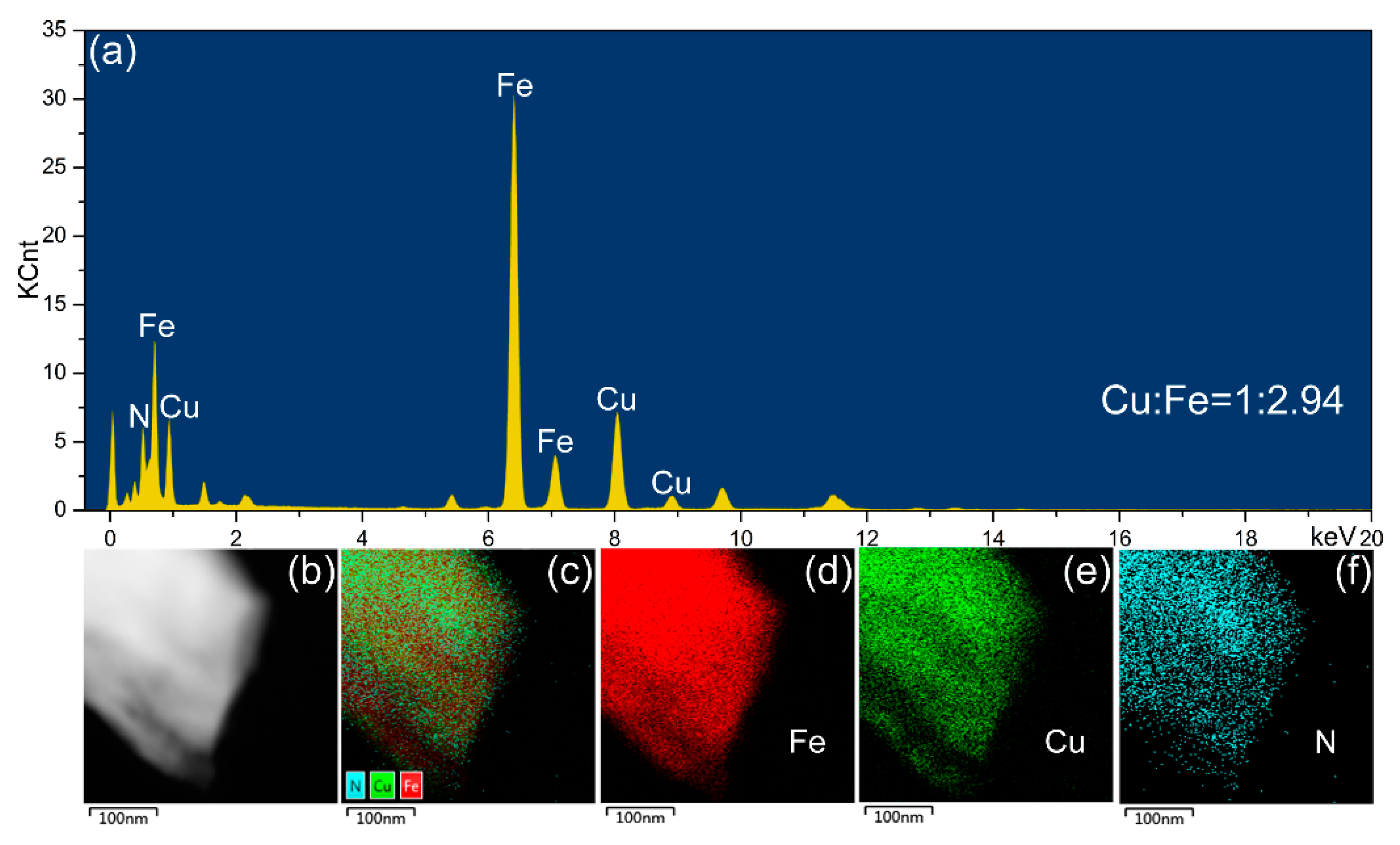
To further reveal the variation of nitrogen content and the stoichiometry of the derived CNF thin films, energy-dispersive X-ray spectroscopy (EDX) measurement of the typical sample CNF/900 was carried out, and the results are shown in Figure 6a, from which the element ratio was determined as Cu:Fe = 1:2.94, close to the stoichiometric ratio of 1:3. Additionally, as for the stoichiometry from EDX results, the accuracy for the light elements has a relatively high error, especially for the elements with atomic number less than 20 [32]. Therefore, it is necessary to point out that the N element is too light to be accurately detected. The results of element mapping are shown in Figure 6b–f, showing the uniform distribution of Cu, N, and Fe.

3.3. Magnetic Properties

The relationship between magnetic moment and magnetic field (MH) of the CNF thin films with different annealing temperatures at room temperature (300 K) is shown in Figure 7. The direction of the applied magnetic field is parallel to the thin film surface. Depending on the thickness, the derived thin films volumes can be obtained. It can be seen that all the thin films are ferromagnetic, and the MH closed curves show similar magnetic field-dependent behavior. As the magnetic field increases, the magnetization first starts to increase and then saturates above 20 kOe. The Ms per unit volume is 579 (~1.09 μB/Fe), 692 (~1.37 μB/Fe), and 950 emu/cm3 (~1.79 μB/Fe), while the Hc is 19.8, 16.7, and 3.7 Oe for the CNF/700, CNF/800, and CNF/900 thin films, respectively. It is observed that a higher Ms is accompanied by a lower Hc, which is the same as the previous reports [33,34,35,36]. The corresponding values are listed in Table 2. As the annealing temperature increases, the Ms increases, which is due to the improvement of crystalline quality and a slight increase of nitrogen content [34]. The Hc decreases with the increase of annealing temperature is mainly due to the increase of Ms and the improvement of crystalline quality. The results show that the CNF thin films can be used as a candidate material for room temperature soft-magnets.

3.4. Electrical Transport Properties

The temperature dependence curves of resistivity are shown in Figure 8 and the measured current was 5 mA. The results show that all samples except CNF/700 thin films exhibit metallic behavior in the temperature range of 5–360 K. As the annealing temperature increases, the resistivity in the whole temperature region decreases. The ρ300K of CNF/700, CNF/800, and CNF/900 are 338.6, 246.7, and 139.4 μΩ·cm, respectively. The resistivity decreases with the increase of nitrogen content, grain size, and crystalline quality [37]. Due to the reduced carrier scattering at the grain boundary, the ρ300K of the prepared CNF thin films is much lower than that of other anti-perovskite bulks [38]. Combined with XRD results, the resistivity is mainly controlled by the microstructure, especially by the grain size: the increase of the grain size leads to the decrease of the grain boundary amounts, indicating that a larger value of grain size will lead to a lower value of resistivity. In addition, as the annealing temperature increases, the grain boundaries can be observed more clearly from the surface FE-SEM results, further indicating the improved crystalline quality.
To study the electrical transport mechanism, the curve of resistivity versus temperature was fitted in different temperature ranges, as shown in the insets of Figure 8. As for the temperature range of 5–110 K, the electrical transport properties can be well fitted considering the 2D-WL model [39], and the high resolution results are shown in inset a of Figure 8. This model based on the inelastic electron–electron and electron–phonon interactions is given by σ(T) = σ0 + ATp + BlnT. The second term of the equation accounts for the electron–electron or electron–phonon interactions. Since the inelastic scattering increases with decreasing temperature, a natural logarithmic temperature dependent term is added to the equation. For the value of the exponent p in the second term, if p ≤ 0.5, the scattering process is dominated by electron–electron interactions for disordered systems [40]. However, if p > 0.5, the electron–phonon interactions dominate the scattering process [41]. In this case, the values of p for all the derived thin films were smaller than 0.5, indicating that electron–electron scattering is dominant in the low temperature region, which is caused by the disordered local magnetic moment. The σ0 and p are 0.015 (μΩ·cm)−1 and 0.133 for CNF/700; 0.026 (μΩ·cm)−1 and 0.128 for CNF/800; and 0.061 (μΩ·cm)−1 and 0.111 for CNF/900, respectively. The corresponding values are listed in Table 2. It can be seen that p decreases as the annealing temperature increases, illustrating that the role of the electron-mediated scattering process strengthens upon increasing annealing temperature along with the electron–electron interactions. Moreover, for a two-dimensional system dominated by localization and interaction effects, σ(T) is logarithmically dependent on temperature (lnT). In metal alloys containing magnetic impurities, the resistivity has a logarithmic relationship with temperature, which depends on the spin-over scattering of local magnetic impurities and conductive electrons [42].
Furthermore, the resistivity of the obtained thin films changes slightly at high temperature. This behavior provides enlightenment for the study of low TCR materials. In general, the temperature dependence of resistivity is not linear over the entire temperature range, but a quasi-straight line can be found in high temperature regions. Meanwhile, TCR is usually defined as ρ0−1(dρ/dT), where ρ0 is the resistivity at 273 K [43]. To obtain the values of dρ/dT, the formula ρ(T) = ρ* + (dρ/dT)T is used to fit the quasi-straight line of each sample in the high temperature region on the ρ(T) curve. The fitting results for CNF/700, CNF/800, and CNF/900 are shown in inset b of Figure 8. The dρ/dT, TCR value, and corresponding temperature range of all derived CNF thin films are shown in Table 2. It can be seen that, for CNF/700 film, TCR value is only 86 ppm/K in the wide temperature range of 220–360 K, which is very similar to manganese-based perovskite resistant compounds [44]. A lower TCR can be obtained by adjusting the annealing temperature properly. Therefore, CNF thin film has the advantages of a very low TCR value, being environmentally-friendly, and good thermal stability, and is a promising low TCR material. Thus far, the reason for the low TCR of perovskite resistant AXM3 is not clear. Here, taking into account the disorder and temperature independent scattering of the sample may be the main factor for low TCR. Combined with the above analysis, lattice shrinkage and TCR value significant changes were observed in all thin films, which provides us with enlightenment to establish the relationship between lattice constant and resistivity [43]. However, the specific origin still needs further experimental and theoretical research.
As mentioned above, all samples show a metallic behavior within the whole temperature range except for the CNF/700 thin film; to further investigate the electrical transport mechanism of the derived thin film, the resistivity behavior between 120 and 230 K can be interpreted by the Möbius criterion [45], as shown in inset c of Figure 8. It can be seen that the d(lnσ)/d(lnT) extrapolates to zero as the temperature decreases, suggesting that the conductivity σ is a finite value and the metallic characteristic of the CNF/700 thin film. Therefore, the CNF/700 thin film can be regarded as a correlated metal in a disordered state.

4. Conclusions

CNF antiperovskite thin films were first prepared by chemical solution deposition with different annealing temperatures. Annealing temperature effects on the microstructures and physical properties were investigated. The results show that the thin films are phase-pure and polycrystalline. Lattice constant, grain size, and crystal quality all increase with the increase of annealing temperature. From the magnetic measurements, CNF can be considered as a new candidate for room temperature soft-magnetic material with a large Ms and a low Hc. As the annealing temperature increases, the Ms increases and the Hc decreases. The derived CNF thin films show metallic electronic transport properties and at high temperatures the series of CNF thin films present a low TCR value, while the electron–electron interaction is prominent at low temperatures. The reported solution methods of CNF thin films will enable extensive fundamental investigation of the microstructures and properties as well as provide an effective route to prepare other antiperovskite transition-metal nitride thin films.

Author Contributions

Conceptualization, Z.H.; methodology, Z.H. and Q.Z.; investigation, Z.H.; data curation, C.L. and J.W.; writing—original draft preparation, Z.H.; writing—review and editing, J.T. and L.Y.; supervision, X.Y.; project administration, X.Z. (Xuebin Zhu) and X.W.; and funding acquisition, X.Z. (Xuzhong Zuo) and X.Z. (Xuebin Zhu). All authors have read and agreed to the published version of the manuscript.

Funding

This work was supported by the National Natural Science Foundation of China (grant numbers 11804003 and 51702002), the Natural Science Foundation of Anhui Province (grant number 1808085QE141), The Research Funds of Anhui Science and Technology University (grant number HCYJ201705), the Foundation of Anhui College students Innovation and Entrepreneurship (grant number 201910879105), and the Open Project Program of the State Key Laboratory of Photocatalysis on Energy and Environment (grant number SKLPEE-202009).

Conflicts of Interest

The authors declare no conflict of interest.

References

  1. Zhang, H.L.; Hui, Z.Z.; Tang, X.W.; Wei, R.H.; Yang, J.; Dai, J.M.; Song, W.H.; Luo, H.M.; Zhu, X.B.; Sun, Y.P. Self-assembled c-axis oriented δ-MoN thin films on Si substrates by chemical solution deposition: Growth, transport and superconducting properties. J. Alloy. Comps. 2017, 704, 453–458. [Google Scholar] [CrossRef]
  2. Hui, Z.Z.; Tang, X.W.; Shao, D.F.; Lei, H.C.; Yang, J.; Song, W.H.; Luo, H.M.; Zhu, X.B.; Sun, Y.P. Epitaxial antiperovskite superconducting CuNNi3 thin films synthesized by chemical solution deposition. Chem. Commun. 2014, 50, 12734–12737. [Google Scholar] [CrossRef]
  3. Peng, X.L.; Yu, S.Y.; Chang, J.S.; Ge, M.H.; Li, J.; Ellis, T.; Yang, Y.T.; Xu, J.C.; Hong, B.; Jin, D.F.; et al. Preparation and magnetic properties of Fe4N/Fe soft magnetic composites fabricated by gas nitridation. J. Magn. Magn. Mater. 2020, 166407. [Google Scholar] [CrossRef]
  4. Gao, B.; Li, X.X.; Ding, K.; Huang, C.; Li, Q.W.; Chu, P.K.; Huo, K.F. Recent progress in nanostructured transition metal nitrides for advanced electrochemical energy storage. J. Mater. Chem. A 2019, 7, 14–37. [Google Scholar] [CrossRef]
  5. Kolaklieva, L.; Chitanov, V.; Szekeres, A.; Antonova, K.; Terziyska, P.; Fogarassy, Z.; Petrik, P.; Mihaiescu, I.N.; Duta, L. Pulsed Laser Deposition of Aluminum Nitride Films: Correlation between Mechanical, Optical, and Structural Properties. Coatings 2019, 9, 195. [Google Scholar] [CrossRef] [Green Version]
  6. Benmalem, Y.; Abbad, A.; Benstaali, W.; Bentounes, H.A.; Seddik, T.; Lantri, T. Thermoelectric, electronic and structural properties of CuNMn3 cubic antiperovskite. J. Comput. Electron. 2018, 17, 881–887. [Google Scholar] [CrossRef]
  7. Guo, X.G.; Lin, J.C.; Tong, P.; Lin, S.; Yang, C.; Lu, W.J.; Song, W.H.; Luo, H.M.; Zhu, X.B.; Sun, Y.P. Anomalous low-temperature heat capacity in antiperovskite compounds. Chin. Phys. B 2017, 26, 026501. [Google Scholar] [CrossRef]
  8. Chen, Z.Y.; Song, Y.; Cai, J.Y.; Zheng, X.S.; Han, D.D.; Wu, Y.S.; Zang, Y.P.; Niu, S.W.; Liu, Y.; Zhu, J.F.; et al. Tailoring the d-Band centers enables Co4N nanosheets to be highly active for hydrogen evolution catalysis. Angew. Chem. Int. Edit. 2018, 57, 5076–5080. [Google Scholar] [CrossRef] [PubMed]
  9. Hui, Z.Z.; Tang, X.W.; Shao, D.F.; Wei, R.H.; Yang, J.; Tong, P.; Song, W.H.; Zhu, X.B.; Sun, Y.P. Self-assembled c-axis oriented antiperovskite soft-magnetic CuNCo3 thin films by chemical solution deposition. J. Mater. Chem. C 2015, 3, 4438. [Google Scholar] [CrossRef]
  10. Meinert, M. Exchange interactions and Curie temperatures of the tetrametal nitrides Cr4N, Mn4N, Fe4N, Co4N, and Ni4N. J. Phys. Condens. Mat. 2016, 28, 056006. [Google Scholar] [CrossRef] [Green Version]
  11. Luo, X.; Liu, S.X. Preparation and chemical stability of iron-nitride-coated iron microparticles. J. Magn. Magn. Mater. 2007, 308, L1–L4. [Google Scholar] [CrossRef]
  12. Monachesi, P.; Björkman, T.; Gasche, T.; Eriksson, O. Electronic structure and magnetic properties of Mn, Co, and Ni substitution of Fe in Fe4N. Phys. Rev. B 2013, 88, 054420. [Google Scholar] [CrossRef] [Green Version]
  13. Li, F.S.; Shen, B.L.; Makino, A.; Inoue, A. Excellent soft-magnetic properties of (Fe, Co)-Mo-(P, C, B, Si) bulk glassy alloys with ductile deformation behavior. Appl. Phys. Lett. 2007, 91, 4096. [Google Scholar] [CrossRef]
  14. Skulmowska, K.; Pelka, R.; Arabczyk, W. Oscillatory kinetics in the process of reduction of nanocrystalline iron nitride. J. Phys. Chem. C 2017, 121, 141. [Google Scholar] [CrossRef]
  15. Mi, W.B.; Guo, Z.B.; Feng, X.P.; Bai, H.L. Reactively sputtered epitaxial γ′−Fe4N films: Surface morphology, microstructure, magnetic and electrical transport properties. Acta Mater. 2013, 61, 6387–6395. [Google Scholar] [CrossRef]
  16. Wang, W.; Kan, X.C.; Liu, X.S.; Feng, S.J.; Liu, C.C.; Rehman, K.M.U.; Shezad, M.; Wu, Q.Y.; Wang, Y.Y. Effect of Cu on microstructure, magnetic properties of antiperovskite nitrides CuxNFe4−x. J. Mate. Sci. Mater. Electron. 2019, 30, 10383–10390. [Google Scholar] [CrossRef]
  17. Costa-Krämer, J.L.; Borsa, D.M.; García-Martín, J.M.; Martín-González, M.S.; Boerma, D.O.; Briones, F. Structure and magnetism of single-phase epitaxial γ′−Fe4N. Phys. Rev. B 2004, 69, 144402. [Google Scholar] [CrossRef] [Green Version]
  18. Subramanyam, G.; Cole, M.W.; Sun, N.X.; Kalkur, T.S.; Sbrockey, N.M.; Tompa, G.S.; Guo, X.M.; Chen, C.L.; Alpay, S.P.; Rossetti, G.A.; et al. Challenges and opportunities for multi-functional oxide thin films for voltage tunable radio frequency/microwave components. J. Appl. Phys. 2013, 114, 191301. [Google Scholar] [CrossRef] [Green Version]
  19. Haertling, G.H. Dielectric and ferroelectric properties of acetatederived PBZT and PSZT thin films. Integr. Ferroelectr. 1995, 7, 279–289. [Google Scholar] [CrossRef]
  20. Lange, F.F. Chemical solution routes to single-crystal thin films. Science 1996, 273, 903–909. [Google Scholar] [CrossRef]
  21. Schwartz, R.W.; Schneller, T.; Waser, R. Chemical solution deposition of electronic oxide films. C. R. Chim. 2004, 7, 433–461. [Google Scholar] [CrossRef]
  22. Mexmain, J. Contribution a l’etude du ferrite cuivreux et de ses solutions solides avec le ferrite cuivrique. Ann. Chim. 1971, 1971, 297–308. [Google Scholar]
  23. Schwartz, R.W. Chemical solution deposition of perovskite thin films. Chem. Mater. 1997, 9, 2325–2329. [Google Scholar] [CrossRef]
  24. Thompson, C.V. Structure evolution during processing of polycrystalline films. Ann. Rev. Mater. 2000, 30, 159. [Google Scholar] [CrossRef]
  25. Zhang, L.; Deng, Y.; Yu, J.Y.; Zhang, M.; Huang, K.; Li, Y.B.; Li, P.; Zhu, X.B. Synthesis and properties of Co5.47N thin films by chemical solution deposition. Mater. Lett. 2018, 225, 145–148. [Google Scholar] [CrossRef]
  26. Matar, S.F.; Houari, A.; Belkhir, M.A. Ab initio studies of magnetic properties of cobalt and tetracobalt nitride Co4N. Phys. Rev. B 2007, 75, 245109. [Google Scholar] [CrossRef] [Green Version]
  27. Ma, X.G.; Jiang, J.J.; Liang, P.; Wang, J.; Ma, Q.; Zhang, Q.K. Structural stability and magnetism of γ′-Fe4N and CoFe3N compounds. J. Alloy. Compd. 2009, 480, 475–480. [Google Scholar] [CrossRef]
  28. Heime, K. Der zusammenhang zwischen metall-halbleiter-barrieren-höhe und elektronegativität sowie kernladungszahl des metalles. Solid State Electron. 1970, 13, 1505–1507. [Google Scholar] [CrossRef]
  29. Thompson, C.V. Grain growth in thin films. Annu. Rev. Mater. Sci. 1990, 20, 245–268. [Google Scholar] [CrossRef]
  30. Yu, F.; Ren, L.; Meng, M.; Wang, Y.; Yang, M.; Wu, S.; Li, S. Growth and magnetic property of antiperovskite manganese nitride films doped with Cu by molecular beam epitaxy. J. Appl. Phys. 2014, 115, 133911. [Google Scholar] [CrossRef]
  31. Moulder, J.F. Handbook of X-ray photoelectron spectroscopy. Phys. Electron. 1995, 230–232. [Google Scholar]
  32. Merey, R.A.; Karajou, J.; Issa, H. X-ray fluorescence analysis of geological samples: Exploring the effect of sample thickness on the accuracy of results. Appl. Radiat. Isot. 2005, 62, 501–508. [Google Scholar] [CrossRef] [PubMed]
  33. Wang, X.; Jia, H.; Zheng, W.T.; Chen, Y.; Feng, S. Structural and magnetic properties of Co-N thin films synthesized by direct current magnetron sputtering. Thin Solid Films 2009, 517, 4419–4424. [Google Scholar] [CrossRef]
  34. Silva, C.; Vovk, A.; Da Silva, R.C.; Strichovanec, P.; Algarabel, P.A.; Gonçalves, A.P.; Borges, R.P.; Godinho, M.; Cruz, M.M. Magnetic properties of Co-N thin films deposited by reactive sputtering. Thin Solid Films 2014, 556, 125–127. [Google Scholar] [CrossRef]
  35. Anzai, A.; Takata, F.; Gushi, T.; Toko, K.; Suemasu, T. Epitaxial growth and magnetic properties of Fe4−xMnxN thin films grown on MgO (001) substrates by molecular beam epitaxy. J. Cryst. Growth 2018, 489, 20–23. [Google Scholar] [CrossRef]
  36. Pandey, N.; Pütter, S.; Amir, S.M.; Reddy, V.R.; Phase, D.M.; Stahn, J.; Gupta, A.; Gupta, M. Effect of interfacial interdiffusion on magnetism in epitaxial Fe4N films on LaAlO3 substrates. Phys. Rev. Mater. 2019, 3, 114414. [Google Scholar] [CrossRef] [Green Version]
  37. Hui, Z.Z.; Meng, Q.M.; Wei, R.H.; Tang, X.W.; Zhu, X.D.; Ouyang, Z.R.; Dai, J.M.; Song, W.H.; Luo, H.M.; Zhu, X.B.; et al. CrN thin films with ultra-low magnetoresistance prepared via solution processing for large-area applications. J. Alloys Compd. 2017, 696, 844–849. [Google Scholar] [CrossRef]
  38. Chattopadhyay, S.K.; Meikap, A.K.; Lal, K.; Biswas, D.; Chatterjee, S.K.; Ghosh, M.; Baba, K.; Hatada, R. Transport properties of iron nitride films prepared by ion beam assisted deposition. Solid State Commun. 1998, 108, 977–982. [Google Scholar] [CrossRef]
  39. Sajitha, E.P.; Prasad, V.; Subramanyam, S.V. Low temperature electrical transport properties of carbon matrix containing iron nanoparticles. J. Appl. Phys. 2009, 105, 073708. [Google Scholar] [CrossRef]
  40. Altshuler, B.L.; Aronov, A.G. Zero bias anomaly in tunnel resistance and electron-electron interaction. Solid State Commun. 1979, 30, 115–117. [Google Scholar] [CrossRef]
  41. Lee, P.A.; Ramakrishnan, T.V. Disordered electronic systems. Rev. Mod. Phys. 1985, 57, 287–337. [Google Scholar] [CrossRef]
  42. Lee, P.A.; Ramakrishnan, T.V. Magnetoresistance of weakly disordered electrons. Phys. Rev. B 1982, 26, 4009. [Google Scholar] [CrossRef]
  43. Lin, S.; Wang, B.S.; Lin, J.C.; Huang, Y.N.; Lu, W.J.; Zhao, B.C.; Tong, P.; Song, W.H.; Sun, Y.P. Tunable room-temperature zero temperature coefficient of resistivity in antiperovskite compounds Ga1−xCFe3 and Ga1−yAlyCFe3. Appl. Phys. Lett. 2012, 101, 011908. [Google Scholar] [CrossRef]
  44. Chi, E.O.; Kim, W.S.; Hur, N.H. Nearly zero temperature coefficient of resistivity in antiperovskite compound CuNMn3. Solid State Commun. 2001, 120, 307–310. [Google Scholar] [CrossRef]
  45. Mobius, A. Comment on metal-insulator-transition in amorphous Si1-xCrx. Solid State Commun. 1990, 73, 215–219. [Google Scholar] [CrossRef]
Figure 1. Flow chart of preparation of CNF thin films by the CSD method.
Coatings 10 00270 g001
Figure 2. XRD patterns of the CNF thin films annealing at different temperatures. The crystal structure of CNF is shown in the left inset. The curve of lattice constants with annealing temperatures is shown in the right inset.
Coatings 10 00270 g002
Figure 3. Surface FE-SEM results of the CNF thin films with different annealing temperatures: (a) 700 °C; (b) 800 °C; and (c) 900 °C. The insets show the histograms of the derived thin films. (d) The thickness of the derived thin films.
Coatings 10 00270 g003
Figure 4. Surface HRTEM results of the CNF thin films with different annealing temperatures: (a) 700 °C; (c) 800 °C; and (e) 900 °C. The SAED patterns of the derived thin films: (b) 700 °C; (d) 800 °C; and (f) 900 °C.
Coatings 10 00270 g004
Figure 5. XPS spectra of the CNF thin films annealed at different temperatures: (a) Cu 2p; (b) Fe 2p; and (c) N 1s.
Coatings 10 00270 g005
Figure 6. EDX spectrum of the typical sample CNF/900 thin film (a); and EDX elemental mapping images of the derived CNF thin film (bf).
Coatings 10 00270 g006
Figure 7. MH curves of the CNF thin films with different annealing temperatures at room temperature (300 K). The left inset shows the changes in Ms and Hc with the annealing temperature, and the right inset is the enlarged MH results to give a clear image at low magnetic fields.
Coatings 10 00270 g007
Figure 8. Temperature dependence of resistivity of CNF annealed at different temperatures. Enlarged images are shown in the insets, which give the fitting curves of the derived thin films at low T region (a) and at high T region (b). and the plot of d(lnσ)/d(lnT) vs. T extrapolates to zero as the temperature decreases (c).
Coatings 10 00270 g008
Table 1. The microstructure and binding energy parameters of CNF thin films (lattice constant of the CNF thin film af).
CNFaf (Å)Average Grain Size (nm)Binding Energy of Cu 2p3/2 (eV)Binding Energy of Fe 2p3/2 (eV)Binding Energy of N 1s (eV)
CNF/7003.79275932.7710.5397.5
CNF/8003.799100933.0710.7397.7
CNF/9003.807114933.2710.8398.1
Table 2. The magnetic and electrical transport parameters of CNF thin films (resistivity at 300 K ρ300K, the two-dimensional weak localization (2D-WL) model fitting parameters σ0 and p, and ρ vs. T slop dρ/dT).
CNFMs (emu/cm3)Hc (Oe)ρ300K (μΩ·cm)σ0 (μΩ·cm)−1pdρ/dTTCR (ppm/K)Temperature Range (K)
CNF/70057919.8338.60.0150.1330.02986220–360
CNF/80069216.7246.70.0260.1280.084347314–360
CNF/9009503.7139.40.0610.1110.064469314–360