Abstract
Carbon-based coatings are used in many applications, particularly in sliding contacts to reduce friction and wear. To improve the tribological properties, these coatings are usually alloyed with metals; W is one of the most used since it helps improve the tribological performance at high temperatures. In this work, we compared the tribological performance of Diamond-Like Carbon alloyed with tungsten (DLC-W) films deposited by direct current magnetron sputtering (DCMS) with films deposited in a hybrid configuration DCMS + high power impulse magnetron sputtering (HiPIMS). The DLC-W coatings were produced with approximately the same W content. One hydrogenated film was deposited with the hybrid configuration for comparison purposes. Microstructure, structure, mechanical properties, and tribological behaviour were used to compare the coatings. All the films displayed a low-order structure of tungsten carbide embedded in an amorphous carbon matrix. The use of the hybrid HiPIMS/DCMS results in coatings with more compact morphologies due to the high ionization fraction of the species produced on the W target (W and Ar ionized species), which primarily will oppose the shadowing effect as the ions will reach the substrate at angles close to 90°. HiPIMS non-hydrogenated film is the more tribological, performing either at room or high temperature (150 °C) due to the much more compact morphology, which avoids the detachment of hard W-C particles, which are responsible for more efficiently scratching the film surface. Experiments revealed that wear behaviour in all the films is governed by the contact of the tribolayer formed on the counterpart composed of W–C, C and W–O against the surface of the film.
1. Introduction
Diamond-like carbon (DLC) coatings are well established for many tribological applications such as internal combustion engines and biomedical devices due to their low wear rate (<10−16 m3/Nm), low coefficient of friction (COF) (<0.2), corrosion resistance, and biocompatibility [1]. Specifically, hydrogen-free DLC coatings, with high levels of sp3 content, displayed very high hardness associated with a low wear rate and friction coefficient when sliding against steel. These coatings perform globally better when compared with the nitrides and carbides-based wear protective coatings used in those industries. However, some important shortcomings must be solved to make this type of coating more attractive for a wider range of applications. First of all, the adhesion of the coatings to the substrate must be improved as well as their mechanical properties [2,3]. Another detrimental feature of DLC coatings is the influence of environmental conditions on their tribological performance such as temperature, and atmosphere to which they are exposed, resulting in different levels of wear rates and friction for the same coating [4,5]. In particular, the performance of DLC coatings at high temperature is limited due to their fast oxidation at temperatures higher than 200 °C [6]. Thus, studies have been conducted to explore new ways to improve the adhesion and to extend their service life at high temperature conditions. To solve those problems, studies on different types of architectures of the interlayers (adhesion and/or gradient layers) and doping of DLC coatings with metallic elements, have been being carried out in the last few decades. The alloying elements used to tune the properties of DLC films are divided into carbides and non-carbide formers, as follows: Ti, Cr, F, W [7,8,9] and Cu and Ag [10,11] respectively. Among those elements, W is the most studied one due to its capacity to improve the tribological behaviour of DLC’s at increased temperatures. Voevodin et al. [12] observed a low COF of 0.30 for a coating with nanocrystalline WC particles embedded in a a-DLC matrix when tested against steel in an ambient air atmosphere (50% RH) at 25 °C. Abou Gharam et al. [13], who investigated the tribological behaviour of WC/a-C coatings deposited by magnetron sputtering against aluminium antagonist sliding partner, reported low COF of 0.18 and 0.12 for 400 and 500 °C, respectively. The formation of WO3 was responsible for the low COF. Jibin et al. [14] also reported a significant improvement in the tribological performances of the WC/a-C coating deposited by magnetron sputtering tested against AISI52100 steel balls at high temperature (200 °C), due to the formation of a continuously compacted tribo-film of WO3. Banerji et al. [15] reported COF values of 0.06 for 100 °C, 0.46–0.54 between 200 °C and 300 °C, 0.07 for 400 °C, and 0.08 for 500 °C, when tested against Ti alloy balls. Bhowmick et al. [16] reported COF of 0.11 when tested against Al-6.5% Si alloy under the influence of pure oxygen atmosphere. In summary, the incorporation of W in the range of 10–15 at. % was shown to improve the tribological properties of DLC coatings at elevated temperatures, when tested against different counterparts. Metal-doped carbon base coatings are being mainly produced/developed by magnetron sputtering Physical Vapor Deposition (PVD) techniques. Different conventional kinds of plasma generators are being used in the production of a-C, DLC coatings, such as: direct current (DC), radio frequency (RF) and pulsed direct current. Recently, a new power supply designated as high power impulse magnetron sputtering (HiPIMS) emerged in the market and started to be used on the production of different types of coatings, including DLC’s. The advantage of HiPIMS in relation to the conventional power supplies relies on the fact that it allows high ionization of the species being deposited and, consequently, can tune the morphology, structure and mechanical properties of films. Recently, Aijaz et al. [17,18] reported that HiPIMS is a suitable technique to produce hydrogen-free DLC films with properties comparable to other DLC films deposited by different state-of-the-art deposition processes.
This work first reports the comparison of the tribological performance at room and high temperature (150 °C) of W-DLC-doped coatings produced with approximately the same W content by conventional DCMS and hybrid DCMS-HiPIMS configurations. For hybrid configuration, one hydrogen free and one hydrogenated W-DLC film were produced to compare with the DCMS film.
2. Experimental Details
The coatings were deposited by PVD magnetron sputtering, on mirror-polished Si wafer, and polished AISI M2 high-speed steel cylinders with a diameter of 50.0 mm and 5 mm thickness with mirror finishing of the surface to be coated. Prior to deposition, all substrates were ultrasonically cleaned in acetone and ethanol baths for 15 min. and then air dried by air blow. A semi-industrial closed field unbalanced magnetron sputtering machine (TEER Coating Ltd., Worcestershire, UK) equipped with four cathodes, evenly distributed in relation to the centre of the chamber, was used for the depositions. The targets (380 mm× 175 mm × 10 mm) were vertically aligned in the chamber. The samples to be coated were mounted in a substrate holder that was placed at a distance of 150 mm from the targets. Three different coatings were deposited in this work, with W content in the range of 10 to 15 at. %, using two different power supplies arrangements, i.e., one coating deposited by DCMS and two coatings produced using a hybrid DCMS-HiPIMS configuration. The W-DLC coating produced by DCMS power supply was sputtered from two high purity C targets and a C target containing 14 W pellets with 20 mm of diameter, evenly distributed along the race track. In order to improve the coatings adhesion, a Cr target was used to produce interlayer and gradient layers as described later. In hybrid DCMS-HiPIMS depositions, the composite C–W target was replaced by a high purity W target and connected to HiPIMS power supply (HiPIMS Cyprium™ III plasma generator, Zpulser Inc.), working in deep oscillation magnetron mode. An example of the HiPIMS DOMS discharge voltage and current oscillating waveforms used in this work is shown in Figure 1.
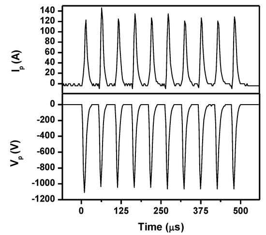
Figure 1.
Representative HiPIMS DOMS discharge current and voltage oscillating waveforms for the W target used for the depositions.
For this configuration, one hydrogen free and one hydrogenated W-DLC film were produced. A schematic representation of the chamber configuration and targets distribution for each of the depositions is shown in Figure 2.
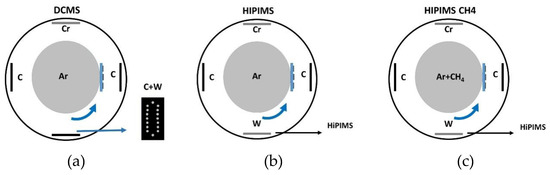
Figure 2.
Schematic illustration of the deposition chamber and distribution of targets used for the films deposited for this work, (a) DCMS, (b) HIPIMS and (c) HIPIMS CH4.
Prior to each deposition, the targets and the substrates were sputter cleaned in an Ar discharge at 0.37 Pa. This stage was made in a two-step procedure. The first step (common for all depositions configurations) was the cleaning of the C targets and substrates by applying a power of 1000 W on each C target and a bias voltage of 600 V on the substrates for 20 min. The next step was the cleaning of the Cr and C–W composite targets for DCMS by applying a power of 2000 W to the Cr target and a power of 1000 W to the C–W composite target. In the case of hybrid configuration, the following pulse was applied on the W target connected to the HiPIMS power supply: average peak power (Pa) of 500 W, charging voltage (DCint) of 250 V, constant voltage time on (ton) of 6 μs, period (T) of 50 μs, and pulse duration (D) of 500 μs. C targets were powered with 2000 W. To improve the adhesion of the films the following sequence of interlayers were deposited: (i) Cr layer by applying 2000 W to the Cr target for 10 min and a pulsed negative bias of -110 V (250 kHz) to the substrate holder (deposition pressure of 0.37 Pa); (ii) gradient layer, decreasing the power applied to Cr target to 0 W and increasing the power applied to the C targets and composite C–W target during 10 min up to 1750 and 1000 W, respectively, and applying same bias voltage as applied to the Cr interlayer; in the case of the coatings deposited with HiPIMS connected to the W target, the bias was set also for −110 V and the power on the Cr target was decreased down to 0 in a period of 10 min. HiPIMS power supply was immediately turned on, as soon as the gradient layer started, with the following pulse characteristic: average power (Pa) of 500 W, DCint of 400 V, constant time (ton) of 6 μs, oscillation period (T) of 50 μs, and a pulse duration (D) of 500 μs. This pulse characteristics were optimized in such a way that the final W content on the coating could be similar to the coating produced by DCMS. In addition, for the hydrogenated W-DLC coating, 10 sccm of CH4 gas was introduced after 5 min of the gradient layer. After the gradient layer, the depositions proceeded with the final power applied to the targets as set for the end of the gradient layer, during 100 min. A summary of the deposition parameters used on the coatings production is shown in Table 1.

Table 1.
Deposition conditions of films.
Hereinafter, for easy coatings identification, the coating deposited by DCMS will be labelled as “DCMS” and coatings deposited by combined DCMS with High-Power Impulse Magnetron Sputtering (HiPIMS) will be labelled as “HIPIMS” and “HIPIMS CH4”, the last deposited under a reactive CH4 and Ar atmosphere. It should be here highlighted that the W target was decided to be connected to the HiPIMS power supply because of their high ionization sputtered potential as compared to C.
A scanning electron microscope (SEM) (ZEISS Merlin—Field Emission Gun) (Zeiss, Oberkochen, Germany) equipped with wavelength dispersive spectroscopy (WDS) was used to observe the surface and cross section morphologies and to evaluate the chemical composition. SiC and WC reference materials were used as standards for calibration of the W and C signals for chemical composition evaluation.
The structure of the coatings was evaluated by X–ray diffraction in grazing incidence of 3° in the range 10–90° with a PANalytical X’Pert Pro MPD system (Cu Kα radiation kα = 1.54 Å, 45 kV and 40 mA) and by green light Raman spectroscopy (Horiba Jobin Yvon microscope, 532 nm/2.33 eV laser excitation). The laser power had to be lowered to 1% of the maximum of 40 mW to avoid the bonding structure thermal crystallization by the laser excitation. The coatings adhesion was evaluated by scratch test with a Rockwell indenter with a diamond tip of 200 µm radius with standard conditions from 0 to 50 N. The scratches were analysed by optical microscopy and the critical adhesion loads were taken from the analysis of those images.
The hardness and reduced Young’s modulus of the films were measured by depth-sensing indentation (MicroMaterials NanoTest platform). A maximum load of 10 mN was selected in order to avoid the influence of the substrate with the maximum indentation depth never reaching values higher than 1/10 of the coating thickness.
Tribological characterization of the coatings was conducted in a standard lab-scale worldwide recognized technique, pin-on-disc sliding equipment, to evaluate the interaction between the films against AISI 52100 material under different environmental conditions. Experiments conducted on pin-on-disc were tested at room temperature (RT) and 150 °C against 10-mm steel balls. The tests were performed under 5 N load, sliding speed of 0.1 m/s and a total sliding distance of 5000 and 3250 m for RT and 150 °C respectively.
3. Results
3.1. Coatings Charcterization
WDS analysis does not allow measurement of the H concentration on hydrogenated produced film, but is a reliable technique to evaluate the W and C concentration; the W/C ratios in atomic concentration for the three coatings deposited are 0.18 for the DCMS coating and 0.15 for HIPIMS and HIPIMS CH4, which is very similar (although slight higher for DCMS film), confirming the production of films with approximately the same W concentration. The thicknesses of HiPIMS’s coatings are lower (1050 and 1150 nm for HIPIMS and HIPIMS CH4) than the coating deposited by DCMS (1730 nm). Since the power applied to C targets placed on cathodes 2 and 4 was the same in both DCMS and HiPIMS’s depositions and the slight higher sputtering rate of W as compared to carbon (0.6 against 0.2 (in Ar atmosphere under 600 eV), the lower thickness of the HiPIMS coatings is primarily attributed to the much lower power applied to the W target as compared to the composite C-W target that also contributes to the C in the coating. In addition, the expected metallic ion back-attraction to the target and the high voltages in HiPIMS power supply as compared to DCMS (1112–1156 against 480 V) can also contribute to the loss of deposition rate [19]. A slight increase of the deposition rate could be noticed for the HIPIMS CH4 film as compared to HIPIMS film due to the fact that CH4 atmosphere works as an additional source for C and H to the coating. A similar feature was also observed for DLC coatings deposited by HiPIMS with increasing of the deposition rate with the C2H2 flow [20].
The cross section and surface morphologies of the as-deposited films are shown in Figure 3. The DCMS coating displays a columnar morphology. The column tops are separated by large void channels and consist of aggregates of smaller sized features, 20–30 nm wide, that give rise to an irregular surface. This kind of rough surface morphology is usually referred to as a cauliflower-type morphology and develops under limited diffusion of the deposited species. Both coatings deposited by HIPIMS show a much more compact morphology, with HIPIMS CH4 film showing a quasi-featureless morphology. Taking into account that the substrate bias was similar in all depositions (−110 V), the more compact morphology of both HiPIMS films is attributed to high ionization fraction of the species produced on the W target (W and Ar ionized species), which primarily will oppose the shadowing effect as the ions will reach the substrate at angles close to 90° and also will bombard the film with high energy. Thus, the deposited species have high energy and the presence of a potential on the substrate will accelerate the ions promoting a more compact morphology [21]. Consequently those films displayed a homogeneous and isotropic surface morphology consisting of fine features, 15–25 nm wide. The slight improvement on compactness of HiPIMS CH4 film corroborates the previous works dealing with the introduction of H on DLC films [20].
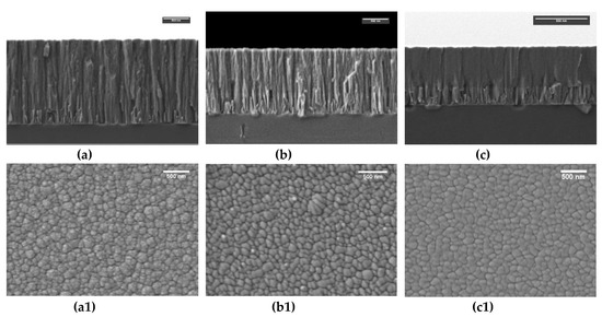
Figure 3.
SEM images of the coatings cross section obtained by SEM (a) DCMS, (b) HIPIMS, (c) HIPIMS CH4, and surface morphology, (a1), DCMS (b1), HIPIMS (c1) HIPIMS CH4.
The structure of the coatings was analysed by Raman spectroscopy and X-ray diffraction. When visible Raman excitation (532 nm) is used to analyse the structure of the coatings, sp2/sp3 ratio cannot be determined as the carbon D and G peaks are results of the vibration of sp2 sites; however, relevant information can be taken from the ID/IG ratio, G peak position and FWHM (full width at half maxim) of the G peak, as it is summarized in Table 2. The Raman spectra for DCMS and HIPIMS films are very similar as shown in Figure 4a. Although, a decrease of the G peak position and FWHM can be noticed, nothing can be inferred about the sp2/sp3 ratio variation because the ratio between ID/IG remains constant. However, for the HiPIMS film deposited under a reactive atmosphere of CH4, the G peak position downshift in conjunction with the ID/IG ratio and G FWHM decreases. This is characteristic of a reduction of the average size of graphite-type sp2-bonded clusters and the promotion of sp3 bond formation [22]. According to the literature, the formation of sp3 bonds in DLC films is mainly achieved by sub-plantation of energetic carbon ions into the subsurface region of the growing film, which promotes the formation of dense films [23,24]. However, the introduction of H has also been reported to promote sp3 bonds formation due to the random covalent network bonding between fourfold sp3 carbon, threefold sp2 carbon and singly coordinated hydrogen atoms. Although slight changes on the voltage and current characteristics of the targets were observed in HiPIMS’s deposition, no significant change on the bombarding conditions are expected as peak power on the targets does not significantly change (product of voltage versus current) when CH4 is introduced to produce the hydrogenated film. Thus, a higher level of sp3 bonds on hydrogenated film are likely due to the presence of H on the film.
Table 2.
Raman analysis of the coatings.
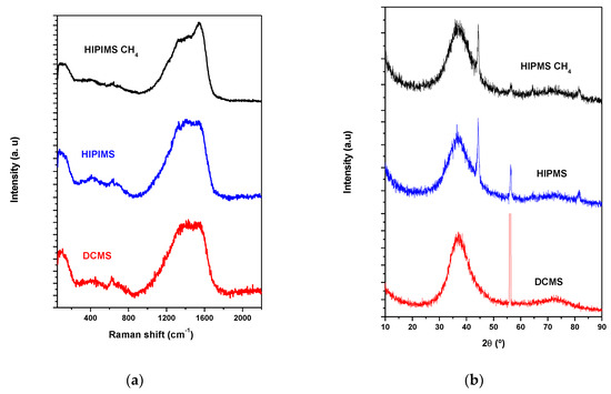
Figure 4.
(a) Raman spectra and (b) X-ray diffraction patterns of the coatings.
Figure 4b shows the XRD diffractograms of the different films in the region 10–90° (2θ). All three coatings displayed only a very broad peak positioned at 37°. This position corresponds well to the main standard peaks of several W–C phases such as WC1-x and WC (see ICDD cards 00-020-1316 and 00-072-0097 respectively). The conjunction of Raman and XRD results allows to suggest that the structure of films consists of a nanocomposite structure of tungsten carbide embedded in an amorphous carbon matrix. Similar results were found in the literature for WC coatings prepared by magnetron sputtering [12,25]. A slight broadening of the XRD diffraction peak of HiPIMS’s films as compared to DCMS film, can be observed, supporting the higher ionization fraction and energy of the deposited species induced by the former power supply. The very sharp peaks positioned at ~44 and 56° corresponds to signals coming from the Cr interlayer (deposited to improve adhesion) and Si substrate, respectively. Cr signal is not detected in DCMS film due to its much higher thickness.
The adhesion, hardness and reduced Young’s modulus of the films were evaluated by scratch testing and nanoindentation. Figure 5a shows one representative scratch test for each of the coatings. Three types of failure modes were observed on the scratch tracks of the coatings: the first cracking (Lc1), first coating shipping (Lc2) and more than 50% coating failure (Lc3). Globally, HiPIMS’s coatings displayed higher critical loads than DCMS film with the HiPIMS CH4 being the better performing. Hardness of HiPIMS film is similar to the hardness of DCMS film, in spite of the much more compact morphology of the former. This suggests that the compact morphology of the HiPIMS is mainly influenced by the higher level of ionization fraction of species, which will fight the shadowing effect. This agrees with the similar Raman spectra between those coatings. HiPIMS CH4 displayed the higher hardness among all the coatings, corroborating the featureless morphology and increase of sp3 bonds shown above. Considering that the only difference in the deposition of this film in relation to HiPIMS is the use of the reactive CH4 atmosphere, we may assume that the increase in hardness is due to the increase of sp3 content of the coatings. This behaviour was also observed by other authors when introducing C2H2 to the discharge [20].
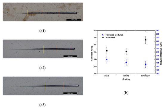
Figure 5.
Adhesion scratches and critical loads of: (a1) DCMS, (a2) HIPMPS, (a3) HIPIMS CH4; Hardness and reduced Young´s modulus of the films (b).
Concerning the evolution of the reduced Young’s modulus, there is a gradual decrease from the DCMS to the HIPIMS CH4 from approximately 200 to 193 GPa. Since the reduced Young’s modulus is related with the type of bonds in the material, the decrease from DCMS to HiPIMS (196 GPa) can be related with the slight decrease of the W content from 14.6 to 12.8 at. %, since there is no indication from the Raman spectra that there are any changes in the structure of the amorphous carbon matrix. A further reduction of the modulus was observed to the HIPIMS CH4, which can be related with the presence of C–H bonds, which avoids establishing sp3 bonds between C atoms, thus lowering the bonding energy.
3.2. Tribological Behaviour
3.2.1. Wear Rate and Friction Coefficient at Room Temperature and 150 °C
The specific wear rate and the average friction coefficient of the coatings tested at RT and 150 °C are shown in Figure 6. At RT, HiPIMS coating displayed the lowest specific wear rate among all the three films, with a COF value of 0.29; the DCMS film has a similar friction coefficient to the HiPIMS one but displays a higher specific wear rate. HiPIMS CH4 coating is the lowest performer despite its lower friction coefficient (0.11) and higher hardness as compared to the other coatings. According to some authors [26], the addition of hydrogen to the coatings results in a decrease of the friction, due to the easier graphitization of the C and an increase of the wear rate associated to the easier removal of the film due to the less bonding energy caused by the presence of H. The specific wear rate and the friction coefficient values are in the range of those reported in the literature for DLC-W coatings with similar chemical compositions [12,14]. The friction coefficient curve of HiPIMS film shows an initial stage of friction lasting 500 m, corresponding to the running in period (see Figure S1 in Supplementary Material). After that, steady state friction is reached; however, the curves present regular oscillations up to the end of the test. These fluctuations are often assigned with the dynamic process of the tribolayer formation [27]. The friction coefficient curve of DCMS film shows an initial stage with high friction, lasting 1300 m. After this stage, stable values are observed, although some periods with lower friction can be observed. The HiPIMS CH4 coating presents the lowest friction with gradual decrease until the first 1000 m and then increases up to 1500 m, reaching a stable COF value of 0.1 approximately.
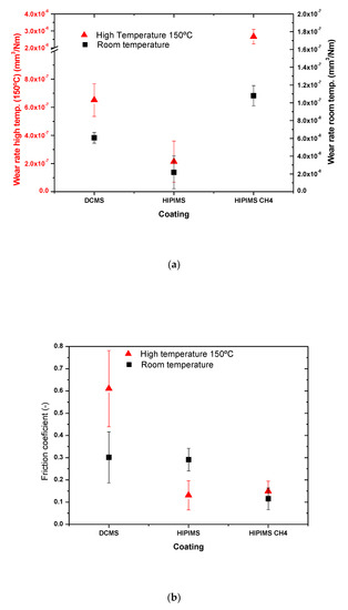
Figure 6.
Specific wear rate at high (150 °C) and room temperature (a); average friction coefficient for both temperatures (b).
The experiments at 150 °C evidenced in all films an increase of specific wear rate in relation to the tests performed at room temperature. Similar to room temperature tests, the film with the best wear resistance was the HIPIMS film, whilst the lowest performer remains the HIPIMS CH4 film, as shown in Figure 6. DCMS film has a specific wear rate almost three times higher than HIPIMS film, and its friction coefficient is the highest amongst all of the films, two times higher than the value measured at RT. For HiPIMS coating, the friction coefficient decreased from 0.3 to 0.1 and for HiPIMS, CH4 film remains approximately the same at 0.1. The friction coefficient curves did not display any significant running in period (see Supplementary Material). Steady state friction of HiPIMS films is smooth, whilst some oscillations can be observed for HiPIMS CH4 film. The friction curve of DCMS film displayed a similar evolution for RT, although with higher friction; however, oscillation periods with low friction are absent.
3.2.2. Wear Mechanisms and Surface Analysis of the Wear Track
The differences of the friction coefficient and wear rate described previously are influenced by many factors, including the experimental test conditions, physical properties of the materials, and wear mechanisms existing on the sliding contact. Thus, the interaction between the film and counterpart was investigated to explain the different behaviours.
Figure 7 presents the SEM images of the coatings wear track and the corresponding craters produced on the sliding balls after tests performed at room temperature. The DCMS film presented a very clean wear track with narrow scratches visible on the centre, which suggests the presence of an abrasion wear mechanism. A closer look at the surface of the tracks revealed the presence of film particles being detached from the surface of the film. The wear track analysed by EDS consists mainly of W and C similar to the pristine surface of the original film. The wear tracks of HiPIMS and HiPIMS CH4 films are similar; they depict very smooth wear tracks; however, very shallow and narrow scratches are visible on the centre part, as a polishing wear mechanism and, therefore, a less severe wear mechanism than for DCMS. These scratches are more pronounced on the HiPIMS CH4 film. In both HiPIMS cases, only a few features regarding the detachment of small particles from the wear track could be observed as compared to DCMS film. EDS analysis performed at the wear track of the films still detects C and W from the original film. However, in the HIPIMS CH4 case, Cr from the interlayer could be detected too, corroborating the high wear rate of this film since the higher depth of the wear allows the detection of the Cr signal from the interlayer. In all the films, particles scattered around the wear tracks are visible. The EDS analysis conducted at those debris revealed the presence of C, W, Fe, and O, suggesting the presence of a mixture of oxides with C from non-oxidized material.
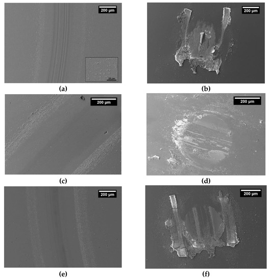
Figure 7.
SEM images of the coating wear track: (a) DCMS, (c) HIPIMS, and (e) HIPIMS CH4, and the crater in the steel ball after testing by pin on disk at room temperature, (b) DCMS, (d) HIPIMS, (f) HIPIMS CH4.
The steel ball tested against DCMS film is fully covered with a transfer layer, whilst, just partial zones of HiPIMS and HiPIMS CH4 films are covered. Accordingly, the scar on the DCMS ball is smaller due to the protection promoted by the adhered layer. The compositions of the transfer layers evaluated at different spots were similar for all the films and equal to the chemical composition of the wear debris scattered around the corresponding wear tracks, suggesting the presence of free C, W–C, W–O and Fe–O as identified by many authors for DLC-W-doped films; the mixture of these phases has been reported to govern the tribological behaviour [12,14,28]. Gharam et al. [13] attributed the low COF and wear rate of DLC-W coatings tested under ambient conditions to the formation of the transfer layers on the ball counterpart. These layers were found to be C-rich with traces of W–O and Fe–O. The lubricity was due to the presence of atmospheric humidity, which dissociates to H and OH, passivating the dangling carbon bonds and minimizing C/C interactions between the layers and the sliding interface. However, W–O oxides should also provide some lubrication due to its recognized lubricious properties [29]. During the tribological experiments, the continuous sliding movement of the ball against the films will break the asperities, either from the ball or the surface of the film, forming free wear debris. The hard WC1-x wear debris from the film can be trapped at the sliding contact interfaces, as well as mechanical adhering to the ball surface, leading to the scratching and acceleration of the films degradation. At the same time, humidity will minimize the C/C interactions which, together with W–O formed by the tribo oxidation of W–C, will provide low friction properties. As the test progresses, the wear debris will be continuously oxidized, some will adhere at the ball surface, and others are injected from the sliding contact to the border of the wear track; however, debris will be continuously detached from the film adhering to the ball counterpart or free sliding on the film surface, promoting a continuous increase of the films’ wear. Despite the similar hardness and friction coefficients of DCMS and HiPIMS film, a higher specific wear rate of DCMS film is caused by the easier detachment of particles due to its more open morphology, as confirmed by the insert in Figure 7a. Thus, the released particles with bigger dimensions will scratch the surface deeper, justifying the abrasion wear shown on the wear track of the DCMS film and its higher specific wear rate. On the contrary, due to the compact morphology of the HiPIMS film, less and smaller wear debris will be detached from the film, leading to a polishing type wear mechanism, which is less aggressive than the previous one, and, thus, to a lower specific wear rate. Part of these wear debris are forming a transfer layer adhered to the counterpart. Pu et al. [14] justified the progressive higher specific wear rate of W-DLC films produced with increasing W content by the presence of increasing amounts of WC1-x phase in the contact, which act as hard abrasive particles accelerating the coating degradation and, therefore, successively increase the wear rates [14]. A similar friction coefficient of DCMS and HiPIMS films is justified by the presence of similar wear debris adhered to the ball surface. In HIPIMS CH4 film, the wear proceeds in a similar way to the other films. However, due to the presence of H in the film, easier graphitization of C is achieved and, therefore, a low friction tribolayer composed of C and W–O is formed, contributing to a lower coefficient as observed in Figure 5b. In addition, the sliding movement of the hard W–C1-x wear debris is able to wear out the film due to the lower chemical bonding promoted by H, consequently giving rise to a higher amount of removal of material.
At high temperature, DCMS film displayed a smooth wear track with a polishing wear type mechanism (see Figure 8). HiPIMS and HiPIMS CH4 films, in addition to the polishing type wear, also display adhered material in the wear track, suggesting that both abrasion and adhesion wear mechanisms take place. Adhesion is more pronounced in the HiPIMS CH4 film. Furthermore, in both films, a significant amount of material can be observed in the border region of the wear tracks. EDS analysis revealed a considerable amount of W, C, Fe, and O which, taking into account the test temperature, should be related to free C, W–O and Fe–O phases. In addition, EDS analysis revealed that in zones where only the W–O signal appears, the O content is approximately three times the at.% amount of W, suggesting the presence of WO3, as was also observed by other authors who investigated the tribological behaviour of DLC-W coatings at high temperature. Similar wear debris were found to have adhered to the ball counterparts for all the films, as shown in Figure 8. Similar to room temperature tests, asperities from either the film and ball surface will break, producing free C, W–C and Fe wear debris. Wear debris will oxidize easier due to the temperature and will adhere to the ball or free sliding at the surface of the film. The oxidation of these particles is faster accelerated by the temperature, which in the contact will promote the polishing type wear mechanism. Despite the less severe wear mechanism at this temperature, the wear rate of the films is higher as compared to RT tests. This can be attributed to: (i) softening of the films with temperature, which provides easier removal of the material; (ii) graphitization of carbon through the transformation of sp3 (diamond-like) to sp2 (graphite-like) [30]; and (iii) absence of humidity, which will not passivate the dangling carbon bonds and will not minimize C/C interactions of the free C particles, thus, C will not provide low friction as for RT. In the case of DCMS film, the wear behaviour will be ruled by the interaction of the material adhered to the ball with the surface of the film. Despite the less-severe wear type observed on the wear track of DCMS, as compared to RT (polishing against severe abrasion), and the similarity of wear debris adhered to the ball counterpart, the friction coefficient of this film is higher at 150 °C due to the absence of humidity. As for RT tests, HiPIMS film displays a lower specific wear rate due to its more compact morphology. Additionally, adhered material at the wear track may provide protection to the wear track, allowing to avoid the direct contact of the tribolayer of the ball and the film surface. The sliding of the HiPIMS film is thus governed by the interaction of the adhered material from the ball and the film surface, which may justify the low friction coefficient as compared to DCMS film. Similar to the HiPIMS film, HiPIMS CH4 film sliding is governed by the interaction between adhered materials at the wear track and ball, justifying a similar COF. However, for the HiPIMS CH4, despite the protection provided by the adhered material on the wear track of the film, the specific wear rate is still the highest among all tested films due to the lower chemical bonding induced by the presence of H.
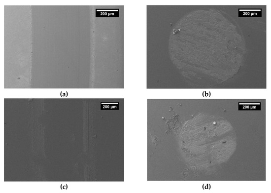
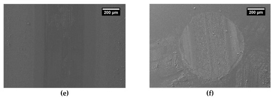
Figure 8.
SEM images of pin-on-disk at high temperature (150 °C) of the coating wear track (a) DCMS, (c) HIPIMS, (e) HIPIMS CH4 and steel ball wear scar, (b) DCMS, (d) HIPIMS and (f) HIPIMS CH4.
4. Conclusions
In this work, W-DLC coatings with similar W content were successfully deposited by PVD with three different configurations on silicon and metallic substrates. All coatings presented good adhesion to the metallic substrates although a slight improvement was observed for the HIPIMS coating. The hardness of the DCMS and HIPIMS films are very similar, however, the HIPIMS CH4 presents a higher hardness due to the higher amount of sp3 in the amorphous carbon matrix confirmed by Raman spectroscopy. The coating with the best overall tribological performance was the HIPIMS coating with the lowest wear at room and high (150 °C) temperatures. This coating also showed the lowest friction at high temperature, lower than when tested at room temperature. The best tribological performance of this film as compared to reference DCMS films is due to its very compact morphology, avoiding the detachment of larger hard W–C particles, which are responsible for the film abrasive wear. The tribological performance of the films is governed by a W–C, C and W–O rich tribolayer that adheres to the ball counterpart.
Supplementary Materials
The following are available online at https://www.mdpi.com/2079-6412/10/4/319/s1, Figure S1: Friction curves representative of the evolution of the friction throughout the tests by pin-on-disk at room temperature, Figure S2: Friction curves representative evolution of the friction throughout the tests by pin-on-disk at high temperature (150 °C).
Author Contributions
Conceptualization, M.E., F.F. and A.C.; methodology investigation and formal analysis, M.E. and F.F.; writing—original draft preparation, M.E. and F.F.; writing—review and editing, M.E., F.F. and A.C. All authors have read and agreed to the published version of the manuscript.
Funding
This research is sponsored by FEDER funds through the program COMPETE—Programa Operacional Factores de Competitividade—and by national funds through FCT—Fundação para a Ciência e a Tecnologia, under the projects UID/EMS/00285/2020, SMARTLUB—ref. “POCI-01-0145-FEDER-031807”, GreenCOAT Ref. M-ERA-NET2/0014/2016, HardRings (AAC n.° 02/SAICT/2017, project n.° 29122) and bilateral collaborative project between Portugal and India (Project number “441.00 INDIA”). F. Fernandes acknowledge the project CZ.02.2.69/0.0/0.0/18_070/0010457.
Conflicts of Interest
The authors declare no conflict of interest. The funders had no role in the design of the study; in the collection, analyses, or interpretation of data; in the writing of the manuscript, or in the decision to publish the results.
References
- Erdemir, A.; Donnet, C. Tribology of diamond-like carbon films: Recent progress and future prospects. J. Phys. D Appl. Phys. 2006, 39, R311–R327. [Google Scholar] [CrossRef]
- Horiuchi, T.; Yoshida, K.; Kano, M.; Kumagai, M.; Suzuki, T. Evaluation of Adhesion and Wear Resistance of DLC Films Deposited by Various Methods. Plasma Process. Polym. 2009, 6, 410–416. [Google Scholar] [CrossRef]
- Wei, C.; Yen, J.Y. Effect of film thickness and interlayer on the adhesion strength of diamond like carbon films on different substrates. Diam. Relat. Mater. 2007, 16, 1325–1330. [Google Scholar] [CrossRef]
- Grill, A. Tribology of diamond like carbon and related materials: An updated review. Surf. Coat. Technol. 1997, 91–95, 507–513. [Google Scholar] [CrossRef]
- Abou Gharam, A.; Lukitsch, M.J.; Balogh, M.P.; Alpas, A.T. High temperature tribological behaviour of carbon based (B4C and DLC) coatings in sliding contact with aluminium. Thin Solid Films 2010, 519, 1611–1617. [Google Scholar] [CrossRef]
- Sánchez-López, J.C.; Fernández, A. Doping and Alloying Effects on DLC Coatings. In Tribology of Diamond-Like Carbon Films; Donnet, C., Erdemir, A., Eds.; Springer: Boston, MA, USA, 2008. [Google Scholar]
- Zhao, F.; Li, H.; Ji, L.; Wang, Y.; Zhou, H.; Chen, J. Ti-DLC films with superior friction performance. Diam. Relat. Mater. 2010, 19, 342–349. [Google Scholar] [CrossRef]
- Ming, M.Y.; Jiang, X.; Piliptsou, D.G.; Zhuang, Y.; Rogachev, A.V.; Rudenkov, A.S.; Balmakou, A. Chromium-modified a-C films with advanced structural, mechanical and corrosive-resistant characteristics. Appl. Surf. Sci. 2016, 379, 424–432. [Google Scholar] [CrossRef]
- Evaristo, M.; Polcar, T.; Cavaleiro, A. Tribological behaviour of W-alloyed carbon-based coatings in dry and lubricated sliding contact. Lubr. Sci. 2014, 26, 428–439. [Google Scholar] [CrossRef]
- Balestra, R.M.; Castro, A.M.G.; Evaristo, M.; Escudeiro, A.; Mutafov, P.; Polcar, T.; Cavaleiro, A. Carbon-based coatings doped by copper: Tribological and mechanical behavior in olive oil lubrication. Surf. Coat. Technol. 2011, 205, S79–S83. [Google Scholar] [CrossRef]
- Bociaga, D.; Komorowski, P.; Batory, D.; Szymanski, W.; Olejnik, A.; Jastrzebski, K.; Jakubowski, W. Silver-doped nanocomposite carbon coatings (Ag-DLC) for biomedical applications—Physiochemical and biological evaluation. Appl. Surf. Sci. 2015, 355, 388–397. [Google Scholar] [CrossRef]
- Voevodin, A.A.; O’Neill, J.P.; Zabinski, J.S. Tribological performance and tribochemistry of nanocrystalline WC/amorphous diamond-like carbon composites. Thin Solid Films 1999, 342, 194–200. [Google Scholar] [CrossRef]
- Abou Gharam, A.; Lukitsch, M.J.; Balogh, M.P.; Irish, N.; Alpas, A.T. High temperature tribological behavior of W-DLC against aluminium. Surf. Coat. Technol. 2011, 206, 1905–1912. [Google Scholar] [CrossRef]
- Pu, J.; He, D.; Wang, L. Effects of WC phase contents on the microstructure, mechanical properties and tribological behaviors of WC/a-C superlattice coatings. Appl. Surf. Sci. 2015, 357, 2039–2047. [Google Scholar] [CrossRef]
- Banerji, A.; Bhowmick, S.; Alpas, A.T. High temperature tribological behavior of W containing diamond-like carbon (DLC) coating against titanium alloys. Surf. Coat. Technol. 2014, 241, 93–104. [Google Scholar] [CrossRef]
- Bhowmick, S.; Lou, M.; Khan, M.Z.U.; Banerji, A.; Alpas, A.T. Role of an oxygen atmosphere in high temperature sliding behaviour of W containing diamond-like carbon (W-DLC). Surf. Coat. Technol. 2017, 332, 399–407. [Google Scholar] [CrossRef]
- Ferreira, F.; Serra, R.; Cavaleiro, A.; Oliveira, J. Diamond-like carbon coatings deposited by deep oscillation magnetron sputtering in Ar-Ne discharge. Diam. Relat. Mater. 2019, 98, 107521. [Google Scholar] [CrossRef]
- Aijaz, A.; Ferreira, F.; Oliveira, J.; Kubart, T. Mechanical Properties of Hydrogen Free Diamond-Like Carbon Thin Films Deposited by High Power Impulse Magnetron Sputtering with Ne. Coatings 2018, 8, 385. [Google Scholar] [CrossRef]
- Ferreira, F.; Serra, R.; Oliveira, J.C.; Cavaleiro, A. Effect of peak target power on the properties of Cr thin films sputtered by HiPIMS in deep oscillation magnetron sputtering (DOMS) mode. Surf. Coat. Technol. 2014, 258, 249–256. [Google Scholar] [CrossRef]
- Lin, J.; Zhang, X.; Lee, P.; Wei, R. Thick diamond like carbon coatings deposited by deep oscillation magnetron sputtering. Surf. Coat. Technol. 2017, 315, 294–302. [Google Scholar] [CrossRef]
- Sarakinos, K.; Alami, J.; Konstantinidis, S. High power pulsed magnetron sputtering: A review on scientific and engineering state of the art. Surf. Coat. Technol. 2010, 204, 1661–1684. [Google Scholar] [CrossRef]
- Robertson, J. Diamond-like amorphous carbon. Mater. Sci. Eng. 2002, 37, 129–281. [Google Scholar] [CrossRef]
- Lifshitz, Y.; Kasi, S.R.; Rabalais, J.W.; Eckstein, W. Subplantation model for film growth from hyperthermal species. Phys. Rev. 1990, 41, 10468–10480. [Google Scholar] [CrossRef] [PubMed]
- Robertson, J. Deposition mechanisms for promoting sp3 bonding in diamond-like carbon. Diam. Relat. Mater. 1993, 2, 984–989. [Google Scholar] [CrossRef]
- Radic, N.; Grzeta, B.; Milat, O.; Ivkov, J.; Stubicar, M. Tungsten–carbon films prepared by reactive sputtering from argon–benzene discharges. Thin Solid Films 1998, 320, 192–197. [Google Scholar] [CrossRef]
- Ronkainen, H.; Varjus, S.; Koskinen, J.; Holmberg, K. Differentiating the tribological performance of hydrogenated and hydrogen-free DLC coatings. Wear 2001, 249, 260–266. [Google Scholar] [CrossRef]
- Vitu, T.; Escudeiro, A.; Polcar, T.; Cavaleiro, A. Sliding properties of Zr-DLC coatings: The effect of tribolayer formation. Surf. Coat. Technol. 2014, 258, 734–745. [Google Scholar] [CrossRef]
- Sánchez-López, J.C.; Martínez-Martínez, D.; Abad, M.D.; Fernández, A. Metal carbide/amorphous C-based nanocomposite coatings for tribological applications. Surf. Coat. Technol. 2009, 204, 947–954. [Google Scholar] [CrossRef]
- Greenwood, O.D.; Moulzolf, S.C.; Blau, P.J.; Lad, R.J. The influence of microstructure on tribological properties of WO3 thin films. Wear 1999, 232, 84–90. [Google Scholar] [CrossRef]
- Semenov, A.P.; Khrushchov, M.M. Influence of Environment and Temperature on Tribological Behavior of Diamond and Diamond Like Coatings. J. Frict. Wear 2010, 31–32, 142–158. [Google Scholar] [CrossRef]


© 2020 by the authors. Licensee MDPI, Basel, Switzerland. This article is an open access article distributed under the terms and conditions of the Creative Commons Attribution (CC BY) license (http://creativecommons.org/licenses/by/4.0/).