Article

Study on the Anti-Friction Mechanism of Nitriding Surface Texture 304 Steel

College of mechanical and transportation, Southwest Forestry University, Kunming 650224, China
*
Author to whom correspondence should be addressed.
Coatings 2020, 10(6), 554; https://doi.org/10.3390/coatings10060554
Submission received: 8 May 2020 / Revised: 29 May 2020 / Accepted: 30 May 2020 / Published: 10 June 2020
(This article belongs to the Section Tribology)

Abstract

:
In order to improve the extensive application of 304 steel in various industrial fields, dimples with different diameter and spacing arrayed on the surface of 304 steel were prepared by laser etching. Then the nitriding treatment was applied on the textured surface and 304 steel matrix surface. The surface microhardness, surface work function, apparent contact angle of the surface before and after nitriding, and surface morphology of the compound modification surface were tested. The tribological properties of five different samples were tested by a rotating friction and wear tester under oil lubrication conditions. The finite element simulation analysis is carried out with a single micro dimple and the upper specimen as the simulation object. The results show that the surface hardness of the compound modification surface is much higher than that of the 304 steel matrix. The surface work function and apparent contact angle of the nitrided surface is larger than that of the 304 steel matrix. These factors lead to the difficulty of abrasive particle stripping, which enhances anti-wear performance of nitrided smooth surface under the lubrication condition. The micro dimple will lead to the change of liquid streamlining, promote the change of liquid pressure in different regions, and result in convergence and divergence regions. But the dynamic pressure of the oil in the micro texture did not play an obvious role in reducing friction at a lower speed. The anti-friction and anti-wear properties of the compound modified surface are better than those of the nitrided smooth surface, which mainly is attributed to lubricant storage in texture and reduction of the real contact area.

1. Introduction

The 304 stainless steel has good corrosion resistance, good heat resistance, excellent low-temperature strength and mechanical properties. However, it has low hardness and is prone to adhesive wear [1]. Therefore, the composite performance of abrasion resistance and corrosion resistance cannot be met at the same time in many cases. For example, occlusion or stickiness often occurs for the transmission shaft, meshing parts or dynamic fittings made of 304 steel. Therefore, it is very important to modify the surface of 304 stainless steel. At present, a reasonable surface texture technology has become an effective method to improve the tribological properties of contact surface with its features of anti-friction, reducing wear, storing oil, etc. Laser surface texture technology is considered one of the most successful methods in the field of surface texture due to its advantages of fast manufacture speed, wide range of materials, high precision, pollution-free environment and good shape and size control ability [2]. Many useful achievements of laser applied microtexture have been obtained [3,4,5]. Moreover, Etsion provided the academic community with a comprehensive review on the subject of laser surface texturing (LST) [6]. It was demonstrated that certain micropocket geometries can reduce friction by up to 40% by an experiment with parallel bearings in reciprocating motion under pure sliding conditions. Valuable experimental work on reducing frictional losses in IC (internal combustion) engines by using laser-etched texture was also carried out by Rahnejat et al. [7]. The result shows that improvements of up to 4.5% could be observed when the laser-etched textured cylinder liner is used, compared to the standard liner. At present, the mechanism of improving the tribological properties of friction pairs by surface texture summarized by researchers mainly include [8]: (1) the additional fluid dynamic pressure effect proposed by Hamilton in 1966. It has become the most important working mechanism of surface texture since Etsion further investigated. It is believed that small convergence wedges and divergence wedges will be formed in the process of liquid flow in the dimples or grooves machined on the surface of friction pairs. The fluid in each micro-convergence wedge will generate a hydrodynamic pressure effect due to the relative motion of friction pairs, thus forming positive pressure; while in the divergence wedge, the “negative pressure” of the fluid is suppressed due to the existence of cavitation. Therefore, additional hydrodynamic pressure is formed between the surfaces, which improves the load-carrying capacity of the fluid film [9]. Up to now, the fluid dynamic pressure principle is still the main basis for surface texture design under high-speed light-load conditions [10,11,12,13]. (2) The theory of abrasive particles collection was proposed by Suh in 1994 [14]. It suggests that the surface groove structure can capture and contain abrasive particles to prevent the friction. (3) The surface texture can store lubricating oil and provide lubricating oil to the surrounding area, which achieves “secondary lubrication” [15] and improves the boundary lubrication performance under the condition of relatively low speed and heavy load.
In the aspect of chemical surface modification, diffusion treatment has been widely used because it can effectively avoid the disadvantage of weak interfacial bonding strength of surface coatings. Among many diffusing technologies, the salt-bath nitriding treatment is widely applied in industrial production because the process is simple and the cost is low. Moreover, the more important reason is that it cannot produce untreatable waste like solid nitrides. The nitriding layer obtained from salt-bath nitriding can greatly improve the corrosion resistance and fatigue limit of the original workpiece [16], and the surface hardness of the material [17]. Fu [18] has conducted low-temperature salt bath nitriding on the Custom 465 martensite steel. The results showed that the wear resistance increased with raising nitriding temperature. Specifically, the wear volume of the samples were reduced by 43% and 82% compared to the untreated samples at 480 and 520 °C nitriding, respectively. Wang [19] has conducted low temperature salt bath nitriding on 0Cr13Ni4Mo martensitic stainless steel. He found that the wear resistance increased with the increase of nitriding temperature, the wear volume was 17.6% of the untreated sample at 510 °C nitriding. However, there are a few studies focusing on the effect of salt bath nitriding on the performance of 304 stainless steel.
Wang [20] believes that the electronic work function plays an important role in the study of material wear and corrosion according to the previous research and analysis. The wear and corrosion always start from the surface. However, there are few reports about the wear and corrosion behavior of materials by using electronic work function. The wear, corrosion and fracture behavior of materials can be reflected through the material surface electron work function, which will play an increasingly important role along with the development of surface engineering technology.
This study is based on the research work of other researchers. The 304 stainless steel surface was treated with salt bath nitriding after laser texturing. The surface work function, apparent contact angle and surface hardness of 304 steel before and after nitriding were measured. The tribological performance of different texture parameters compound modification surface was tested on the rotary friction and wear testing machine. The research results can provide a good technical guidance for the wide and effective practical application of 304 stainless steel.

2. Experimental Materials and Processes

The 304 steel plates were purchased from Hecheng metal insulation materials Co., Ltd. (Shenzhen, China). The size of specimens was 10 mm × 10 mm × 2 mm. The dimples arrayed on the surface of 304 steel with the different diameter and spacing were prepared by using M-DPSS-50 semiconductor laser marking machine. Diameter and spacing were 100, 200, 300 μm, respectively. The related parameters: current was 8 A and voltage was 15 V. The laser etching method was used for filling. After calculation, the surface area percentage of each parameter texture was 19.625%. The surface topography of the texture surface with different parameters and single dimple topography was detected by YM 200 Optical microscope (Hengxu, Jinan, China) and ZeGage 3D optical profilometer (Zygo Corporation, Middlefield, CT, USA).
The same method used in literature [21] was used to conduct salt bath nitriding on the surface of the samples. A D/MAX-Ultima+ X ray diffractometer (Rigaku, Tokyo, Japan) was used to determine the phase composition after nitriding treatment. A Fisherscope H100C Micro hardness Measurement System (Fisher Technology, Sindelfingen, Germany) was used to obtain the surface hardness. The applied load in the measurement was 800 mN. Six points were randomly selected for each sample to measure, and the average value was taken to improve the measurement accuracy. The apparent contact angle of the five samples was determined by the German Easy Drop contact angle measuring instrument. The apparent contact angle measurement method is static observation, and the liquid was pure distilled water. The initial droplet volume was 2 μL. Kelvin probe force microscopy (KPFM, KP Technology Ltd., Caithness, UK) was applied to determine the electronic work function on the sample surface before and after nitriding. KPFM was conducted under atmospheric and at room temperature.
The tribological properties of five samples were tested by a ChemInstruments high-temperature tribometer (ChemInstruments, West Chester Township, OH, USA). The samples were 304 steel, 304 nitriding smooth surface, and different parameter surface textured composite nitriding 304 steel. Experimental load was 15 N (which corresponds to a nominal contact pressure of about 30 MPa), the speed was 10 mm/s, the total number of rotating circles (the diameter of a circle was 2 mm) was 5000, and the lubrication condition was No. 100 base oil lubrication with a frequency of one drop per 300 s. The upper sample of the friction pair was a ZrO2 ceramic ball with 5 mm of diameter and hardness of HV1600. The schematic of the friction test can be seen in Figure 1. The friction coefficient was recorded by the automatic recording system of the friction and wear-testing machine. After the wear test, the morphology of the sample surface was measured by a ZeGage 3D optical profilometer. Three dry friction experiments on composite modified surfaces were carried out in order to analyze the effect of abrasive particles on the friction characteristics in the process. The experimental conditions and parameters were in good agreement with those of oil lubrication. The wear surface state diagram under lubricant friction conditions and dry friction conditions was detected by a YM 200 Optical microscope.
The finite element simulation analysis was carried out with a single micro dimple and the upper specimen was the simulation object. This numerical simulation experiment used FLUENT software of 2019R2 version. The control equation used FLUENT software to solve the flow field problem is N-S equation, which can reflect more details in the flow field at low Reynolds number. The grid type used in the discretization of flow field was a hexahedral grid with the size of 0.00109 mm × 0.00109 mm × 0.00109 mm.

3. Experimental Results and Discussion

3.1. Properties of Materials after Nitriding in Salt Bath

3.1.1. Surface Phase Composition and Nitriding Thickness

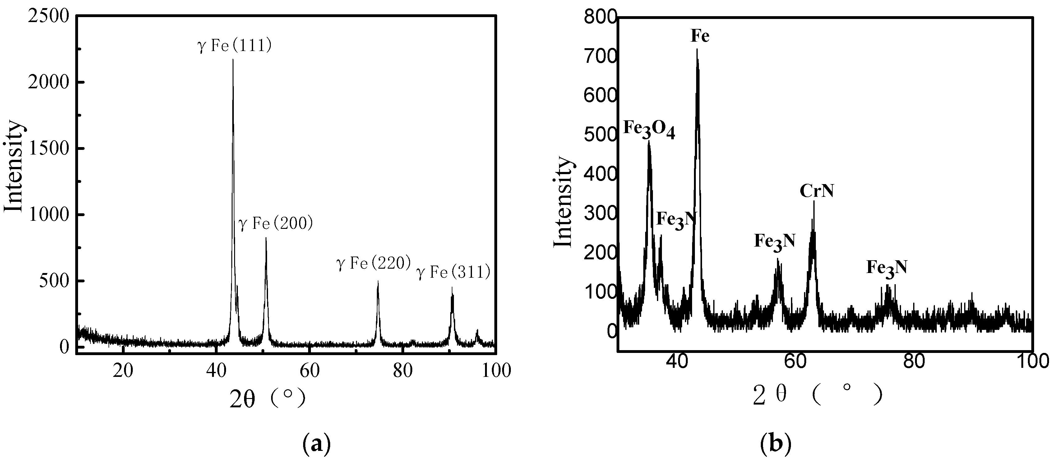
According to the X-ray diffraction (XRD) results of previous work which is shown in Figure 2 [21], the original structure of 304 steel was austenitic stainless steel, and the diffraction peaks of Fe3N and CrN appeared on the surface of the sample after salt bath nitriding. Figure 3 is a the cross-sectional SEM image of the nitriding sample. It can be seen from the figure that the dividing line between nitride layer, white light layer and matrix is very clear, and the thickness of nitride layer is about 30 μm.

3.1.2. Surface Microhardness

The surface hardness determined by Fisherscope microhardness tester is shown in Figure 4. It can be seen from Figure 4a that the average hardness of the smooth 304 steel surface is about 1838 N/mm2, while the average hardness of the smooth nitriding surface is about 5150 N/mm2. This can be attributed to the precipitation of the CrN phase with high hardness in the nitriding layer [22], resulting in a significant increase in the surface hardness.

3.1.3. Surface Apparent Contact Angle

The apparent contact angle is a physical quantity to evaluate the wettability of the solid surface. The higher the free energy of the solid surface, the easier it is to be wetted by liquid drops and the smaller the apparent contact Angle. The lower surface free energy reduces the wetting property of the solid surface and increases the apparent contact angle. Figure 5 shows the apparent contact angle of deionized water on the surface of the samples (smooth surface before and after nitriding). It can be seen that the average apparent contact angle of the smooth 304 steel surface is about 86°, and the surface apparent contact angle after nitriding is about 101°. Apparent contact angles are dictated by the triad of the specific interface energies, namely the liquid/vapor, the liquid/solid and the solid/air specific surface energy. But in the three-phase tension, it is the surface-free energy of the solid that determines the angle. It indicates that the free energy of the material surface is decreased after nitriding in the salt bath. Li [23] believes that the surface free energy is higher, the organization is more unstable. As the surface free energy is higher, the organization becomes more unstable.
The wettability of the compound modified surface with different size parameters is shown in Figure 6. It can be seen from the figure that the apparent contact angle of the 200 and 300 μm textured surface is smaller than that of the substrate. On the contrary, the apparent contact angle of 100 μm textured surface is larger than that of the substrate.

3.1.4. Surface Work Function

In the detection of this study, the relationship between electronic work function and the measured value of the sample can be expressed as:
ϕ sample = ϕ tip + CPD e
ϕsample and ϕtip are the work function of the sample and the work function of the needle tip, respectively. Contact potential difference (CPD) is the measured value.
Table 1 shows the measured electronic work function of 304 steel and 304 steel after nitriding. According to the calculation formula, the electronic work function of the nitriding steel is 5.1 + 702.55/1000 = 5.802 eV. The electronic work function of 304 steel is 5.1 + (−562.9)/1000 = 4.537 eV. The results show that the electronic work function of the material surface increased after nitriding. The change of free energy and work function of the material surface after nitriding is consistent with the research results of Ji [24]. That is, the amount of surface energy reflects the energy levels of the surface, which is directly related to the stability of the material surface and the possibility of reconstruction. There is an inverse relationship between surface energy and its work function.

3.2. Surface Morphology after Laser Texturing

Figure 7 shows the topography of textured surface with different parameters and the 3D topography of single dimple. It can be seen from Figure 7a–c that the laser textured 304 steel surface has formed very regular and clearly different diameters and spacing dimples. Figure 7d–f show the three-dimensional topography of a single dimple with different diameters. It can be seen that the dimple depth with a diameter of 100 μm was 39.60 μm. The central convex area of the dimple increased as the diameter of the dimple increased. The height of the convex area in the middle of each sample is lower than the macroscopic plane of the sample. It can be presented from Figure 7e,f that there is a ring groove formed around the convex area. The depth of the 200 μm dimple is 22.86 μm, and the depth of 300 μm dimple is 19.63 μm. The cause of the middle convex area is that the laser processing method is the filling etching, and the repeated irradiation etching of the laser point causes the material to splash, thus forming the convex area in the central region. These convex areas in the central region result in the decrease of the surface apparent contact angle of the 200 and 300 μm samples.

3.3. Friction and Wear Characteristics

The comparison of friction coefficient variations on different surfaces is shown in Figure 8. This indicates that the friction coefficient curve of 304 steel substrate surface is significantly higher than one of other friction pairs in the initial stage. It results from the running-in stage of the friction pair. After that, the friction pairs are in the optimal friction contact state, which leads to flattening the friction coefficient curve. The friction coefficient of the nitrided smooth surface increases slowly from the beginning of the test to the 2500 cycles, and then tends to be stable. However, the friction coefficient of the nitrided smooth surface was significantly lower than that of 304 steel substrate surface in the whole test process. One of the reasons is the large increase of surface hardness after nitriding. In addition, the surface energy of nitriding surface is less than that of the 304 steel substrate surface. According to Bowden and Tabor’s basic law of tribology, the magnitude of friction is related to the surface energy of the contact surface [25]. The low surface energy modification can reduce the surface energy of the sample, which decreases the adhesion force and friction between the sample surface and the ceramic ball. The friction coefficient of the surface compound modified friction pairs with different parameters have gone through the process of slowly increasing and then gradually decreasing, and finally becoming stable. The friction coefficient of all the compound modified friction pairs is obviously lower than that of the smooth surface of nitriding at the stable stage. In the first half of this experiment, the friction coefficient of the compound modified friction pairs is slightly higher than that of the nitrided smooth surface because the surface roughness of the textured surface increases due to laser dissolution. That is to say, nitriding modification can improve the friction property of the sample, while the friction properties of the composite modified sample is more prominent.
Figure 9 shows the worn surface morphology of different samples. In Table 2, the comparison of the surface deepest depth wear marks and the width of five samples is presented. It can be found from Figure 9 and Table 2 that the 304 steel substrate surface deepest depth of the wear marks is 6.54 μm. However, the deepest depth of the wear marks is 5.49 μm after nitriding modification, which is much smaller than that of 304 steel substrate. The deepest depth of the wear marks of the compound modified surface with different parameters was 2.62 μm (100 μm dimple), 4.21 μm (200 μm dimple) and 3.35 μm (300 μm dimple), respectively. There was a significant decrease compared with the surface of 304 substrate. In terms of the width of the wear marks, 304 steel wear marks width is significantly greater than that of other wear marks’ width of each samples. This is because the nitriding surface can significantly improve the wear resistance of 304 steel. Moreover, the work function of nitriding surface is larger, and the surface free energy is smaller. Lu’s [26] study shows that the higher electronic work function of the material induces the higher electronic stability. It has a higher resistance property to the structural and electronic state changes, which leads to the difficulty of dissection of the abrasive particles from the surface of the matrix. It also can be seen from Table 2 that the wear marks widths of 100 and 200 μm laser-textured surface is larger than that of the smooth nitrided surface. The reason for this phenomenon is that the edge of the texture spattered by laser etching is prominent on the surface of the substrate, while the dimple number of 300 μm texture in the friction wear area is relatively small, which results in the smaller wear marks’ width. However, the wear marks’ depth of the three compound modified surfaces is much smaller than that of the nitriding smooth surface, which indicates that the compound modified surface has good wear resistance.
From Figure 8 and Table 2, it can be seen that there is no obvious regularity in the change of the data of the three compound modified surfaces, but the friction coefficient and wear marks depth are lower than those of the non-textured nitriding surface, that is, the anti-friction and anti-wear properties of the compound modified surface are better than those of the nitriding smooth surface.
At present, researchers have summarized four mechanisms for friction reduction and wear resistance of micro-textured surfaces. The first theory is the reduction of the actual contact surface area in the friction process. The second theory is hydrodynamic pressure effect theory. The third one is secondary lubrication theory. The lubricant stored in the texture was added to the surface of the friction pair and a continuous oil film formed under the effect of two lubricating effects during the friction process. The fourth is that the abrasive generated in the process of friction and wear can be stored in the texture.
In order to verify whether the second theory has any effectiveness in this study, the finite element simulation analysis is carried out with a single micro dimple and the upper specimen as the simulation object. The fluid is 100# base oil with density of 801.3 kg/m3 and thickness of 10 um (from Figure 7, it can be seen that the edge of each micro dimple has a prominent part close to 10 μm due to laser action, so the oil film thickness is set to 10 μm in the simulation.). The control model is the laminar model. The lower wall is a moving wall with a velocity of 0.01 m/s. The upper wall and the lateral wall are stationary. The SIMPLE method is used to solve the problem, and the convergence accuracy is 10−6. The calculation results are imported into ANSYS CFD-Post software (2019R2) for analysis. The internal pressure distribution and streamline trend characteristics are obtained.
The schematic diagram of the two-dimensional geometric model of the flow field are shown in Figure 10. The cylinder is the circular micro dimple part, while the hexahedron represents the oil film. Both of them constitute the fluid model of this study. The thickness of the oil film is h, and the depth of the circular micro dimple is m. The surface ABCD is the upper wall, the surface EFGH and the cylindrical surface are the lower wall, which is the moving wall.
Figure 11 shows the pressure distribution on the upper surface of the flow field. The dark blue area is the pressure divergence area, and the red area is the pressure convergence area. It can be seen from the figure that there is a hydrodynamic effect in the texture flow field of a circular micro dimple.
This is because the left end of the circular micro dimple is the place where the fluid flows into the circular micro dimple, which suddenly increases in the volume of the flow making the fluid disperse, resulting in a rapid drop in the pressure there. The right end of the circular micro dimple is where the fluid flows out of the circular micro dimple, the decrease of the volume of the space leads to the close accumulation of the fluid and the pressure convergence zone formation. The diameter of the micro dimple has a direct influence on the pressure distribution in the fluid pressure divergence region. Figure 11a shows that when the diameter of the micro dimple is 100 μm, the flow field has an area with a brief increase of pressure in front of the pressure divergence zone. The opposite phenomenon appears in Figure 11b,c, the pressure decreases slightly in the front of the flow pressure divergence area. The pressure divergence region and convergence region are mainly distributed in the two ends of the circular micro dimple. It can be seen from Figure 11 that with the increase of the diameter of the micro dimple, the pressure in the middle part of the divergence area and the convergence area does not change dramatically. The absolute value of the maximum pressure in the convergence area is almost the same as that of the minimum pressure in the divergence area.
Figure 12 is the cloud image of lower surface pressure distribution in the flow field with different diameters micro-dimples. It can be seen from the figure that there are also pressure divergence and convergence zones in the flow field of circular micro dimple. Different from Figure 11, the pressure divergence area and convergence area occupy a small area. However, the absolute values of pressure peaks in the two regions are significantly higher than those in the two regions in Figure 11. The absolute value of the maximum pressure in the convergence area is almost the same as that of the minimum pressure in the divergence area.
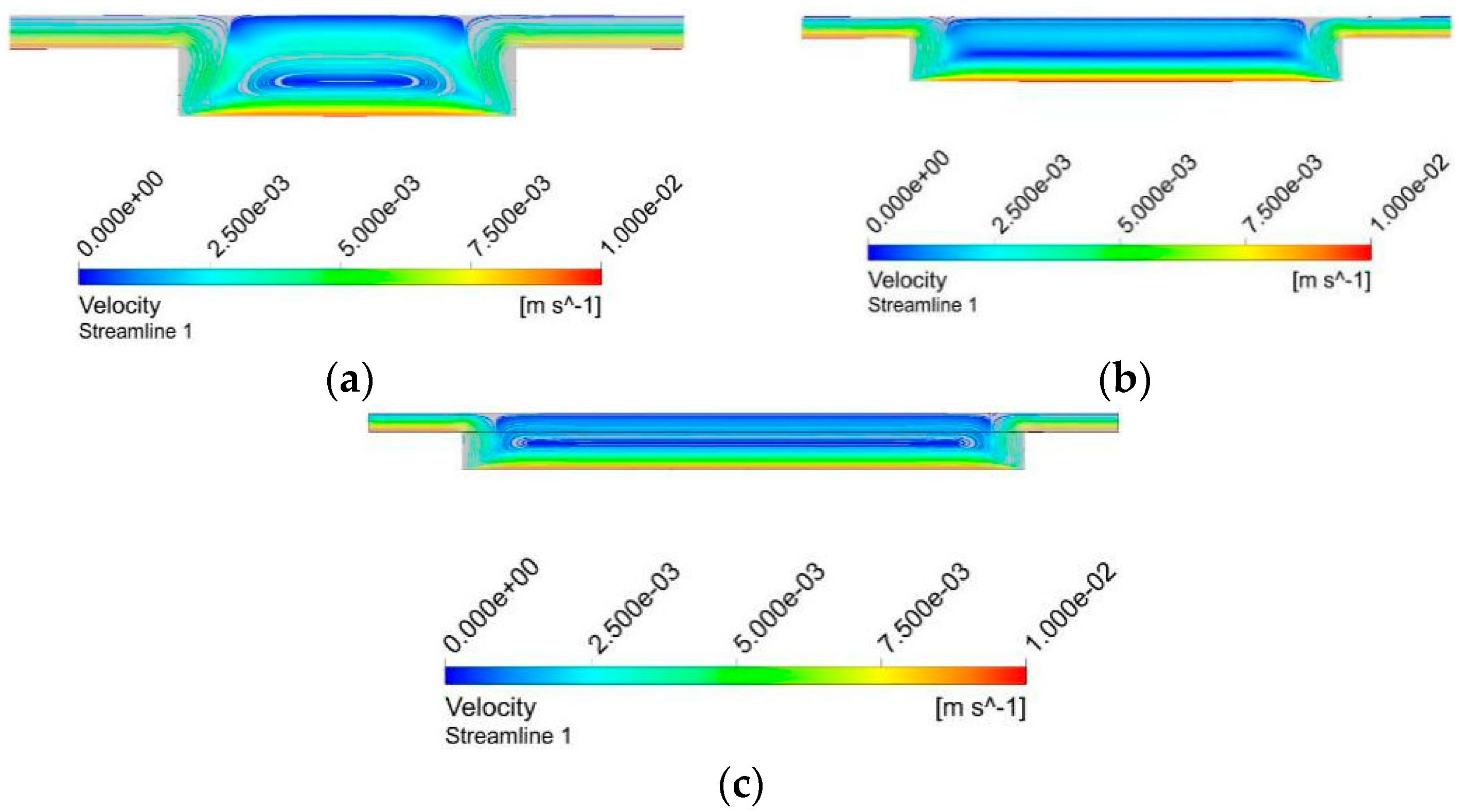
Figure 13 shows the streamlines distribution of axial plane in the flow field of different circular micro-dimples. It can be seen from Figure 13 that eddy current of different intensity appeared in the circular micro dimples flow field. With the increase of the diameter of the circular micro dimples, the shape of the eddy current in its internal flow field changes from the short flat shape shown in Figure 13a to the medium flat shape shown in Figure 13b, and finally to the long flat shape shown in Figure 13c.
In order to further explore the influence of the coupling relationship between dynamic pressure and inertia effect on fluid bearing capacity, the pressure variation curves of the axial plane in the flow field of micro-dimples of different sizes are listed as shown in Figure 14. The position of the maximum value and the minimum value of the curve in the figure corresponds to that of the divergence and convergence areas in Figure 11. The peak pressure in divergence and convergence area determines the maximum value and the minimum value of the curve. The curve change between the minimum value and the maximum value is affected by the eddy current intensity in Figure 13. As the shape of the vortex is gradually compressed, the internal velocity decreases gradually, and the slope of the curve from the minimum value to the maximum value also decreases gradually.
It can be seen from the above analysis that the micro dimple will lead to the change of liquid streamline, promote the change of liquid pressure in different regions and result in convergence and divergence regions. However, the lubricating oil in the texture did not actually lead to the increase or decrease of the total bearing capacity of the samples above and below the friction, that is, the dynamic pressure of the oil in the micro texture did not play an obvious role in reducing friction at a lower speed. Under this lubrication condition, the hydrodynamic pressure effect is difficult to reflect. But the oil storage effect of micro-texture can play a good tribological action.
Figure 15 and Figure 16 present wear surface state diagram under dry and lubricant friction conditions, respectively. It can be clearly seen that a large number of abrasive grains appear in the wear mark position of the specimen under dry friction condition, and a lot of abrasive grains are stored in the texture dimples where the wear mark is located. By contrast, under oil lubrication, no abrasive particles were observed at all locations of the wear marks. The reason for this phenomenon is that there are relatively few abrasive particles under oil lubrication, and the abrasive particles can be taken away from the wear marks along with the flow of lubricating oil. Therefore, the fourth tribological mechanism summarized by its predecessors is not applicable.
According to Bowden and Tabor, the tribology basic law [27] is: F = τ·Ar, where F is friction force, τ is the interfacial shear strength and Ar is real contact area. This formula obviously indicates that the friction force is proportional to the shear strength and the real contact area. In this study, the contact area of the friction pair was large when the surface was not texture-modified. So, the friction coefficient was high. The area occupancy of the texture of each parameter is 19.625%, and a real contact area with the test ball was significantly reduced, so the adhesion and friction of the material was effectively reduced.
In conclusion, the friction reduction and wear resistance of a textured composite nitriding surface in this study are mainly attributed to lubricant storage in texture and a reduction of the real contact area.

4. Summary

In this study, the surface work function, apparent contact angle and surface hardness of 304 steel before and after nitriding were determined. The tribological properties of the compound modified surface were tested on a rotating friction and wear tester. The following conclusions were drawn:
  • The CrN phase with high hardness is precipitated in the nitrided surface layer, which causes the obvious increase of surface hardness. The free energy of the material surface is decreased after nitriding in the salt bath. As the surface free energy is higher, the organization becomes more unstable. The electronic work function of the material surface increases after nitriding, which is directly related to the stability of the material surface and the possibility of reconstruction. There is an inverse relationship between surface energy and its work function;
  • The surface wear resistance of the nitrided surface is better than the 304 surface. The reason for this phenomenon is that the surface hardness is greatly increased due to nitriding. Moreover, the work function of the nitriding surface is large, and the surface free energy is small, which leads to the difficulty of dissection of the abrasive particles from the surface of the matrix;
  • The micro dimple will lead to the change of liquid streamline, promote the change of liquid pressure in different regions and result in convergence and divergence regions. But the dynamic pressure of the oil in the micro texture did not play an obvious role in reducing friction at a lower speed;
  • The anti-friction and anti-wear properties of the compound-modified surface are better than those of the nitriding smooth surface, which are mainly attributed to lubricant storage in the texture and reduction of the real contact area.

Author Contributions

Conceptualization, W.C. and M.X.; methodology, W.C.; software, W.S.; validation, W.C., M.X., and W.S.; formal analysis, W.C.; data curation, M.X.; writing—original draft preparation, W.C.; writing—review and editing, W.C.; supervision, W.C. All authors have read and agreed to the published version of the manuscript.

Funding

This research was funded by National Natural Science Foundation of China, grant number 51865053.

Conflicts of Interest

The authors declare no conflict of interest.

References

  1. Li, C.; Yin, Y.; Guo, L.; Qin, L. Effect of Boron and Molybdenum Alloying Treatment on Abrasion Resistance of 304 Stainless Steel. Hot Work. Technol. 2015, 44, 144–146. (In Chinese) [Google Scholar]
  2. Wang, M. Effect of Combined Treatment with Plasma Nitriding and Laser Surface TEXTURING on Microstructure and Vacuum Tribological Properties of Titanium Alloy. Master’s Thesis, China University of Geosciences, Beijing, China, 2018. [Google Scholar]
  3. Olofinjanal, B.; Martin, C.L.; Ajayi, O.O.; Ajayi, E.O. Effect of laser surface texturing(LST) on tribochemical films dynamics and friction and wear performance. Wear 2015, 332, 1225–1230. [Google Scholar] [CrossRef] [Green Version]
  4. Liu, H.B.; Wan, D.P.; Hu, D.J. Microstructure and wear behavior of laser textured and micro-alloyed Co-based WC and TiC composite sintered-car bide coating. J. Mater. Process. Technol. 2009, 209, 805. [Google Scholar] [CrossRef]
  5. Sun, Q.C.; Hu, T.C.; Fan, H.Z.; Zhang, Y.; Hu, L. Dry sliding wear behavior of TC11 alloy at 500 ℃: Influence of laser surface texturing. Tribol. Int. 2015, 92, 136. [Google Scholar] [CrossRef]
  6. Etsion, I. State of the art in laser surface texturing. J. Tribol. 2005, 127, 248–253. [Google Scholar] [CrossRef]
  7. Rahnejat, H.; Balakrishnan, S.; King, P.D.; Howell-Smith, S. In-cylinder friction reduction using a surface finish optimization technique. Proc. Inst. Mech. Eng. Part D J. Automob. Eng. 2006, 220, 1309–1318. [Google Scholar] [CrossRef] [Green Version]
  8. Yu, H.; Huang, W.; Wang, X. Dimple patterns design for different circumstances. Lubr. Sci. 2013, 25, 67–78. [Google Scholar] [CrossRef]
  9. Wang, J.; Wang, X. State of the art in innovative design of surface texture. J. Mech. Eng. 2015, 51, 84–95. [Google Scholar] [CrossRef] [Green Version]
  10. Han, J.; Fang, L.; Sun, J.; Ge, S. Hydrodynamic lubrication of microdimple textured surface using three- dimensional CFD. Tribol. Trans. 2010, 53, 860–870. [Google Scholar] [CrossRef]
  11. Zhang, J.; Meng, Y. Optimal design of surface texture in parallel thrust bearings. J. Mech. Eng. 2012, 48, 91–99. [Google Scholar] [CrossRef]
  12. Yin, B.; Lu, Z.; Liu, S.; Fu, Y.; Wang, Y. Theoretical and experimental research on lubrication performance of laser surface texturing cylinder liner. J. Mech. Eng. 2012, 48, 91–96. [Google Scholar] [CrossRef]
  13. Ma, C.; Zhu, H.; Sun, J. Applicable equation study of lubrication calculation of surface texture based on CFD analysis. J. Mech. Eng. 2011, 47, 95–106. [Google Scholar] [CrossRef]
  14. Suh, N.P.; Mosleh, M.; Howard, P.S. Control of friction. Wear 1994, 175, 151–158. [Google Scholar] [CrossRef]
  15. Wang, X.; Kato, K. Improving the anti-seizure ability of SiC seal in water with RIE texturing. Tribol. Lett. 2003, 14, 275–280. [Google Scholar] [CrossRef]
  16. Jacquet, P.; Coudert, J.B.; Lourdin, P. How different steel grades react to a salt bath nitrocarburizing and post-oxidation process: Influence of alloying elements. Surf. Coat. Technol. 2011, 205, 4064–4067. [Google Scholar] [CrossRef]
  17. Cai, W.; Meng, F.N.; Gao, X.Y.; Hu, J. Effect of QPQ nitriding time on wear and corrosion behavior of 45 carbon steel. Appl. Surf. Sci. 2012, 261, 411–414. [Google Scholar] [CrossRef]
  18. Fu, H.; Zhang, J.; Wu, S.; Huang, J.F.; Gao, W.; Lian, Y. Effect of low-temperature salt bath nitriding on the corrosion and wear resistance of custom 465. Chin. J. Eng. 2016, 38, 235–240. [Google Scholar]
  19. Wang, H. Effect of low temperature nitriding on surface modification of pump with 0Cr13Ni4Mo steel. Foundry 2016, 65, 783–786. [Google Scholar]
  20. Wang, Y.; Wang, L. Research progress of electron work function on the wear and corrosion behavior of materials. Chin. Mater. Sci. Technol. Equip. 2011, 5, 1–5. (In Chinese) [Google Scholar]
  21. Chen, W.; Liu, X.; Zheng, L. Study on the friction characteristics of 304 steel with composite surface modification. Ind. Lubr. Tribol. 2017, 69, 248–258. [Google Scholar] [CrossRef]
  22. Li, G.; Peng, Q.; Li, C.; Wang, Y.; Chen, S.; Wang, J.; Shen, B. Study on micro-structure of a QPQ complex salt bath heat-treated 17-4 Ph stainless steel. Nuclear Power Eng. 2007, 28, 59–62. [Google Scholar]
  23. Li, J.; Sun, F.; Wang, S.; Yang, X.; Hu, J. Catalysis effect and mechanism of pre-oxidation on direct current plasma nitriding. Trans. Mater. Heat Treat. 2014, 35, 182–187. (In Chinese) [Google Scholar]
  24. Ji, D.; Wang, S. Study of surface energy and work function of hex metals by first-principles calculation. Acta Metall. Sin. 2015, 51, 597–602. [Google Scholar]
  25. Yoshimitsu, T.; Nakajima, H.; Nagaoka, H. Synthesis of the CD ring system of paclitaxel by atom- transfer radical annulation reaction. Tetrahedron Lett. 2002, 43, 8587. [Google Scholar] [CrossRef]
  26. Lu, H.; Hua, G.M.; Li, D.Y. Dependence of the mechanical behavior of alloys on their electron work function—An alternative parameter for materials design. Appl. Phys. Lett. 2013, 103, 261902. [Google Scholar] [CrossRef]
  27. Roach, P.; Shirtcliffe, N.J.; Newton, M.I. Progress in superhydrophobic surface development. Soft Matter 2008, 4, 224–240. [Google Scholar] [CrossRef]
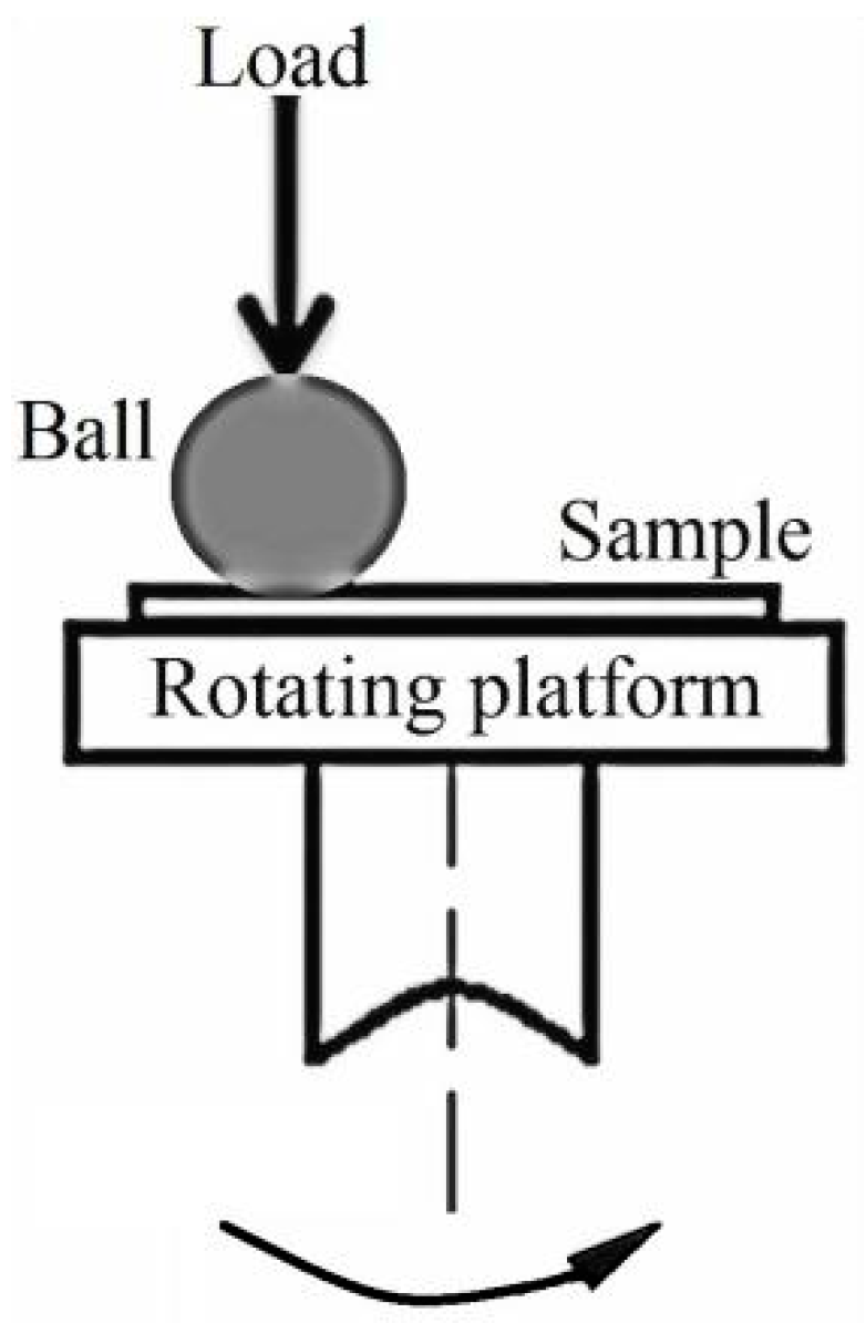
Figure 1. Schematic of the friction test.
Coatings 10 00554 g001
Figure 2. The results of X-ray diffraction (XRD) before and after nitriding (a) 304 steel surface, (b) nitriding surface [21] (Reproduced from [21] with permission. Copyright 2017 Emerald Publishing).
Coatings 10 00554 g002
Figure 3. The cross-sectional SEM image of nitriding sample.
Coatings 10 00554 g003
Figure 4. Microhardness of 304 steel smooth surface before and after nitriding (a) 304 steel, (b) nitriding 304 steel.
Coatings 10 00554 g004
Figure 5. The image and value of surface apparent contact angle: (a) 304 steel, (b) nitriding 304 steel.
Coatings 10 00554 g005
Figure 6. The image and value of surface apparent contact angle of the surface texture compound nitriding sample: (a) 100 μm, (b) 200 μm, (c) 300 μm.
Coatings 10 00554 g006
Figure 7. Surface topography of texture surface with different parameters and single dimple topography: (a,d) 100 μm, (b,e) 200 μm, (c,f) 300 μm.
Coatings 10 00554 g007
Figure 8. Friction coefficient variation curves of different friction pairs.
Coatings 10 00554 g008
Figure 9. Three-dimensional topography of worn sample surfaces: (a) 304 steel, (b) nitriding smooth surface, (c) 100 μm surface, (d) 200 μm surface, (e) 300 μm surface.
Coatings 10 00554 g009
Figure 10. Schematic diagram of the two-dimensional geometric model of the flow field.
Coatings 10 00554 g010
Figure 11. The cloud image of upper surface pressure distribution in the flow field with different diameters micro-dimples: (a) 100 μm, (b) 200 μm, (c) 300 μm.
Coatings 10 00554 g011
Figure 12. The cloud image of lower surface pressure distribution in the flow field with different diameter micro-dimples: (a) 100 μm, (b) 200 μm, (c) 300 μm.
Coatings 10 00554 g012
Figure 13. Streamlines distribution of axial plane in the flow field of different circular micro-dimples: (a) 100 μm, (b) 200 μm, (c) 300 μm.
Coatings 10 00554 g013
Figure 14. Pressure change curve at the axial plane of flow field of different size circular micro dimples: (a) 100 μm, (b) 200 μm, (c) 300 μm.
Coatings 10 00554 g014
Figure 15. Wear surface state diagram under dry friction conditions.
Coatings 10 00554 g015
Figure 16. Wear surface state diagram under lubricant friction conditions.
Coatings 10 00554 g016
Table 1. Electronic work function of sample surface before and after nitriding (measured value).
Serial No.304 Steel (eV)Nitriding Surface (eV)
1−612.5737.3
2−569.1760.2
3−542.4762.8
4−548.7729.2
5−541.9523.2
Average−562.9702.5
Table 2. Comparison table of surface deepest depth of the wear marks and width of each sample.
SamplesWear Marks Width (μm)Deepest Depth of the Wear Marks (μm)
304 steel516.96.5
Nitrided surface419.75.5
100 μm surface457.32.6
200 μm surface457.34.2
300 μm surface401.23.4