Article

Gas Technique of Simultaneous Borocarburizing of Armco Iron Using Trimethyl Borate

Institute of Materials Science and Engineering, Poznan University of Technology, Pl. M.Sklodowskiej-Curie 5, 60-965 Poznan, Poland
*
Author to whom correspondence should be addressed.
Coatings 2020, 10(6), 564; https://doi.org/10.3390/coatings10060564
Submission received: 7 May 2020 / Revised: 5 June 2020 / Accepted: 11 June 2020 / Published: 14 June 2020
(This article belongs to the Section Surface Characterization, Deposition and Modification)

Abstract

:
The gas boriding process is an appropriate technique used for increasing the hardness and wear resistance of iron and steels. However, the boron halides (e.g., BCl3, BF3) are rarely used as a boron source during gas boriding in industry due to the toxic character of these reagents. The possibility of the use of organic compounds as a boron source in plasma assisted processes was the instigation to determine the possibility of applying these agents for gas boriding. In the present work trimethyl borate was used as an organic boron source. The use of a N2–H2–B(CH3O)3 atmosphere ensured the appropriate conditions for the simultaneous gas borocarburizing of Armco iron. The process was carried out at 1223 K (950 °C) for 2 h. The produced layer consisted of two zones: an outer zone containing a diffusion of boron atoms and an inner zone containing a diffusion of carbon atoms, under the outer zone. Due to the reduction of trimethyl borate with hydrogen, free atoms of carbon were released for the gas atmosphere. Therefore, there existed favorable conditions for carburizing. Unfortunately, the formation of a carburized layer was the reason for the difficult diffusion of boron atoms. As a consequence, the boron diffusion front was hindered, and the outer boride layer was relatively thin (ca. 7.8 µm). The boride layer contained only Fe2B phase, which was characterized by high hardness in the range from 1103 HV0.01 to 1546 HV0.01. The presence of iron borides in the outer layer was also the reason for increased wear resistance in comparison with untreated Armco iron.

1. Introduction

Boride layers are characterized by many attractive properties, e.g., high hardness, low friction coefficient, high wear resistance, high heat resistance even at elevated temperatures, high corrosion resistance or resistance to attack by molten metals. Diffusion of boron atoms into the surface of ferrous alloys causes the formation of the iron borides FeB and Fe2B. Various boriding techniques, such as powder-pack boriding, liquid boriding, gas boriding, plasma boriding or laser boriding, have been developed in order to produce boride layers on iron and steels [1]. The most often applied agent during powder-pack boriding is boron carbide (B4C) which has been used for boriding of pure iron [2,3] and different grades of steels [4,5,6,7,8,9]. The powder-pack boriding process can be carried out using other powders, e.g., containing boric acid (H3BO3) as a boron source [10,11]. Boriding of ferrous alloys is also possible with the use of a liquid media such as molten salts as in [12,13] or without electrolysis [14,15]. In these processes, borax (Na2B4O7) was applied as a boron source. A specially promising effect was obtained in the case of electrochemical boriding in molten borax [12]. Even the short process duration (5 min) resulted in the formation of a borided layer which was characterized by a high thickness (up to 40 μm, depending on the process temperature). The highest temperature of process (1273 K) and longest duration (2 h) caused the formation of a very thick layer (ca. 250 μm), composed of FeB and Fe2B phases [12]. Boriding at a temperature above 1273 K (1000 °C) for long duration was not preferred due to the segregation of alloying elements in the alloy steels and phase transformations in these materials. For these reasons, the appropriate technique to help avoid these problems was plasma-assisted boriding [16,17,18,19,20,21,22]. The activation of the gas atmosphere and substrate surface under glow discharge conditions allowed a decrease in process temperature to even below 973 K (700 °C). Nowadays, laser boriding [23,24,25] is an interesting alternative for the diffusion boriding processes because of the formation of thick boride layers on steel substrates. Laser boriding allows the brittleness of the boride layer to be diminished due to the characteristic composite microstructure. Moreover, the presence of a thick heat-affected zone between the laser-borided layer and substrate material results in lower hardness gradient. This causes better bonding of the laser-borided layer with the substrate material [25]. Unfortunately, the roughness and waviness of the top-surface as well as the presence of microcracks are usually the main disadvantages of the laser boriding technique. In recent years, the gas boriding of pure iron and steels using boron halides as a boron source has become a well-known and developed technique [26,27,28,29]. The process of gas boriding provides the possibility of controlling the activity of boron during boriding [26,27,28]. The usage of boron halides (BCl3, BF3) for gas boriding causes the formation of very thick boride layers which are characterized by high hardness and wear resistance.
The important technique of improvement of these surface properties has become the borocarburizing process. Such a process results in the formation of gradient multi-component borocarburized layers, which are characterized by increased abrasive wear resistance [30] and increased low-cycle fatigue strength [31] in comparison with the typical borided layers. The gaseous borocarburizing process is carried out by means of tandem diffusion processes: carburizing followed by boriding [30,31,32,33]. Sometimes, the process of gas carburizing precedes the laser alloying with boron, also called laser boriding [34]. The gas borocarburized layers, formed by gas boriding of previously carburized substrate, consists of two main zones: an iron boride zone near the top-surface and a carburized zone below the iron borides. In the case of gas borocarburizing the iron borides show a tendency towards a loss of the needle-like nature, due to the high concentration of carbon in the carburized layer. The hardness gradient between iron borides and low-carbon substrate is reduced because of the presence of a carburized zone. In the paper [34], laser boriding, instead of gas boriding, was proposed to produce gradient borocarburized layers. The obtained microstructure consisted of three main zones: a laser-borided zone (eutectic mixture of iron borides and martensite), a heat-affected zone as a hardened carburized zone and the rest a carburized layer without heat treatment. These two techniques of two-step borocarburizing require the application of two different separate processes. Therefore, they can be recognized as time-consuming methods.
The simultaneous process of borocarburizing is carried out by cathode plasma electrolytic saturation with boron and carbon. The cathode plasma electrolytic borocarburizing of low-carbon steel in aqueous electrolyte containing 15 wt % of borax and unknown percentage of C3H8O3 [35] provides a microstructure which consists of three characteristic zones: a loose top layer, a boride layer and a transition layer. The loose top layer contained FeB and Fe3C phases as well as Fe2O3 oxides and is easy to remove by polishing. After polishing, the boride layer containing Fe2B borides remains close to the surface. The transition layer is composed of Fe3C and Feα phases and appears below the boride layer. A similar boride layer is produced with the use of electrolyte of higher borax content (30 wt %) [36]. Only the Fe3O4 oxide appears additionally in the loose top layer. In the paper [37], the Fe2B phase was identified additionally in the loose top layer after cathode plasma electrolytic borocarburizing of low-carbon steel. Whereas the composition of the boride layer was still the same (Fe2B).
The development in plasma-assisted boriding with the use of organic compounds, e.g., triethyl borane (C2H5)3B [20] or trimethyl borate (OCH3)3B also written as B(CH3O)3 [21,22], was the instigation to analyze the possibility of applying these boron sources during a simultaneous gas borocarburizing process. In paper [21], boriding was carried out by the pulsed DC plasma-assisted chemical vapor deposition technique (PACVD). The substrate material was 42CrMo4 low-alloy steel. The boron source was trimethyl borate (OCH3)3B, and the parameters of boriding were as follows: temperature 1103 K (830 °C), pressure 800 Pa, time 1 h, flow rates of gases—2700 mL/min for Ar and 540 mL/min for H2. Unfortunately, the voltage was not provided by the authors. The important parameter of the process was also the flow rate of trimethyl borate. The thickness of the boronized layer increased on increasing the flow rate of the boron source. When the flow rate of trimethyl borate was higher than 0.8 g/h, the thickness of the boronized layer did not increase further with increasing flow rate. On the other hand, when the flow rate of (OCH3)3B was higher than 0.5 g/h, a borocarburized zone occurred. Moreover, the thickness of this borocarburized layer increased on increasing the flow rate of trimethyl borate. However, the produced boride layers were characterized by a relatively low thickness (8 μm).
In the present study, the analysis of simultaneous gas borocarburizing with the use of trimethyl borate as a boron precursor is presented. The process was carried out like a typical gas process of thermochemical treatment, i.e., at a minimal overpressure in the furnace chamber and without glow discharge. The thermodynamic aspects of the process as well as the microstructure, microhardness, and wear resistance of the produced borocarburized layer were analyzed.

2. Material and Methods

2.1. Material

Armco iron (commercially pure iron) was used for the investigation. Its nominal composition is presented in Table 1 according to the data provided by the supplier of the material. Specimens in the shape of a ring (external diameter 20 mm, internal diameter 12 mm, and height 12 mm) were used.

2.2. Simultaneous Gas Borocarburizing

The devices used for simultaneous gas borocarburizing are shown in Figure 1. The borocarburizing atmosphere consisted of a mixture of nitrogen and hydrogen as well as trimethyl borate as a source of boron and carbon active atoms. The main device consisted of the vertical tubular furnace (1) equipped with three independent heating zones and the quartz retort (3), into which the samples were inserted. During the process, the upper part of the quartz retort was cooled by water (2). The furnace was equipped with a power-supply system (4) which contained a control system for the temperature with the use of a personal computer (5) and HTMonit software (version 5.2). Obviously, the temperature near the treated samples was monitored by a separate measuring system (6) using a thermocouple.
The gas delivery system consisted of the following: cylinder with N2-H2 mixture (18), cylinder with N2 (19), cylinder with B(CH3O)3 (16) inserted into the heating sand bath (15), rotameter (12) and mass-flow meters (17). The N2-H2 gas mixture of high purity (6.0) contained 75 vol % N2 and 25 vol % H2. The atmosphere consisting of N2-H2 mixture flowed during boriding through the cylinder with trimethyl borate. The amount of trimethyl borate in the boriding atmosphere (N2–H2–B(CH3O)3) resulted from its vapor pressure which depended on the temperature. Therefore, in order to obtain an adequate temperature, the cylinder with trimethyl borate was put into the sand bath and heated by a special device (15). The heating system of trimethyl borate was equipped with a separate measuring system (11). Before heating of the tubular furnace started, the vacuum pump (7) was switched on in order to remove the air from the gas delivery system. It was checked by a vacuum-meter (14) equipped with a pressure pickup (13). Then, the heating process was started. In order to protect the samples against oxidation, the heating process was carried out in a nitrogen atmosphere. While the furnace was heating up to a temperature of 1223 K (950 °C), a gas mixture of N2-H2 was delivered into the quartz retort at a flow rate of 100 L/h. Then the delivery of trimethyl borate was activated in the same way that the N2-H2 mixture had been let into the cylinder, with B(CH3O)3. The continuous gas borocarburizing in the N2–H2–B(CH3O)3 atmosphere was carried out for 2 h. After the process was finished, the samples were cooled in a nitrogen atmosphere.

2.3. Microstructure Analysis

After the simultaneous gas borocarburizing process, phase analysis was performed with a PANalytical EMPYREAN X-ray diffractometer (Poznan, Poland). Cu Kα radiation was used for this study. For microstructure observations, the samples were cut out from across the produced layer. The cross-sectional sample of the boride layer was prepared in the plane perpendicular to the top-surface of the sample. Then, the preparation of the metallographic specimen was performed. The sample was mounted in conducting resin, ground using abrasive papers because of the different granularity, and polished by applying a water slurry of Al2O3. The etching solution consisted of 5% nital (5% solution of HNO3 in C2H5OH). The microstructures of the specimens were observed with an optical microscope LAB 40 (OM, OPTA-TECH, Poznan, Poland) and a scanning electron microscope (SEM) MIRA3 (TESCAN, Poznan, Poland).

2.4. Microhardness Test

The microhardness was investigated on the polished and etched cross-sections of the specimen. The Micromet II tester (Buehler, Poznan, Poland) equipped with Vickers diamond tip was used for this study. Due to the low thickness and high porosity of the produced iron boride layer, a low indentation load of 10 gf (0.0981 N) was used. The load was applied for 15 s. The diagonals of indentations were measured, and the hardness values were calculated.

2.5. Wear Resistance Test

Wear resistance experiments were arranged as a block-on-ring test in dry sliding conditions. In this test, a stationary block (counter-specimen) was pressed against the outer surface of a rotating ring (specimen) under a load of 49 N. The specimen and counter-specimen were in non-conformal contact. Sintered carbide S20S was used as a counter-specimen. It was composed of hard carbides (WC, NbC, TiC, TaC) in a cobalt matrix. Wear resistance tests were performed for 2 h with a change in the counter-specimen every half hour. During the test, the sliding speed of the specimen was equal to 0.26 m/s. It resulted from a rotational speed of the specimen n = 250 r.p.m. and its diameter (20 mm). Simultaneously, the total sliding distance was 1884 m. Before the wear resistance test and after every 30 min of test duration, the specimen was weighed using an analytical balance with an accuracy of ±0.05 mg.
Wear resistance was determined based on two factors:
—mass wear intensity factor Imw according to the equation:
I m w = Δ m S · t
where: Δm is mass loss (mg), S is friction surface (cm2), t is friction time (h). Imw factor was defined as the specimen mass loss per friction surface and unit of time, corresponding to the slope of the straight line in the wear diagram (under conditions of stabilized wear).
—Relative mass loss Δm/mi according to the equation:
Δ m m i = m i m f m i
where: mi is initial mass of specimen (mg), Δm is mass loss (mg), mf is final mass (mg).
Relative mass loss Δm/mi was defined as the ratio of mass loss Δm to initial mass mi.
The worn surfaces of specimen and counter-specimen were analyzed using a scanning electron microscope TESCAN MIRA3 equipped with an energy dispersive spectrometer (EDS). The corresponding EDS patterns of the selected elements, such as iron, boron, cobalt, tungsten, niobium as well as oxygen, were shown.

3. Results and Discussion

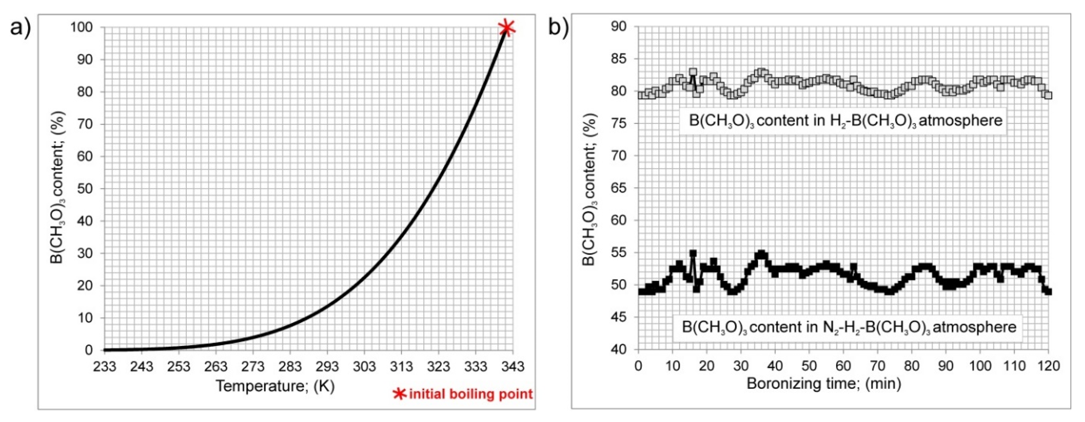
3.1. Thermodynamic Fundamentals of the Gas Borocarburizing Process

During gas borocarburizing, the trimethyl borate was delivered into the quartz retort with the flow of a N2-H2 mixture through the cylinder containing trimethyl borate B(CH3O)3. The role of the carrier gas was to transport the trimethyl borate vapors into the furnace in which the specimens were placed in the middle of the quartz retort. For this reason, the trimethyl borate should be in a gaseous state when the carrier gas flows through the cylinder. The concentration of B(CH3O)3 in the gas atmosphere N2–H2–B(CH3O)3 depended on its vapor pressure. A general equation describing the change in vapor pressure vs. the temperature is as follows:
log P = 13.1756 1357.14 ( T 134.33 )
where: P is vapor pressure (mm Hg), T is temperature (K).
The vapor pressure of trimethyl borate could be calculated as a function of temperature T (K) using Equation (3). The concentration of B(CH3O)3 in the gas atmosphere depended on the relationship between temperature and equilibrium vapor pressure of the trimethyl borate. The dependence of content of B(CH3O)3 in the entire gas atmosphere on its temperature is shown in Figure 2a. Obviously, the increase in temperature of trimethyl borate caused an increase in its vapor pressure up to its initial boiling point of 341.4 K (68.4 °C). The cylinder with trimethyl borate was inserted into the heating sand bath and was heated to the temperature within a range from 321 to 324 K (48–51 °C). The time dependence of trimethyl borate addition, during the gas borocarburizing process, is shown in Figure 2b. The average B(CH3O)3 content was equal to 80.9 vol % in relation to H2, and 51.5 vol % in relation to the entire atmosphere N2-H2-B(CH3O)3 used. A high content of trimethyl borate in the gas atmosphere was required in order to conduct the simultaneous gas borocarburizing process.
The main aim of the use of carrier gas, composed of the mixture of nitrogen and hydrogen (75 vol % N2 and 25 vol % H2), was to obtain improved safety. Previously, such a carrier gas was successfully applied during gas boriding of iron and nickel alloys with the use of boron trichloride (BCl3) as a boron source [26,33,38,39]. The use of a mixture of nitrogen and hydrogen enabled a diminished percentage of toxic boron trichloride to be applied in relation to the entire boriding atmosphere. The boriding process became more environmentally friendly. The addition of nitrogen to the carrier gas did not influence the BCl3 content in relation to the whole atmosphere. However, the content of boron trichloride in relation to hydrogen (participating in reactions with BCl3) could be significantly increased in this case, especially if the percentage of nitrogen was appreciable [1]. It was assumed that the nitrogen did not participate in reactions proceeding in the atmosphere at a temperature of 1223 K (950 °C). The same relationships were observed in the case of the use of trimethyl borate as the boron and carbon source. The content of B(CH3O)3 in relation to H2 was relatively high (see Figure 2b), and the gas atmosphere was safer. Taking into account that the temperature of trimethyl borate (321–324 K) was only slightly lower than its boiling point (341.4 K), there were limited possibilities to increase this parameter. Hence, the use of only hydrogen as the carrier gas would result in a diminished percentage of B(CH3O)3 in relation to H2. Therefore, the mixture of H2 and N2 seemed to be more advantageous.
The formation of atomic boron during the simultaneous gas borocarburizing process could proceed as a sequence of reactions: (4), (6), (7) and (8) or (4), (6), (9), (10), (11) and (12). The atomic carbon on the substrate was produced as a result of the chemical reactions between the boron source B(CH3O)3 and hydrogen as the reducing agent (4) and based on reaction (5). There were no data regarding the mechanism of formation of free active boron and carbon atoms in the considered borocarburizing atmosphere. Therefore, the possible reactions are proposed in this study. They proceed in order to provide the free active atoms of carbon and boron on the treated surface. According to Equation (4), the first step during gas borocarburizing consists of the reduction of trimethyl borate with hydrogen. As a result, atomic carbon (active free atoms of carbon) could be created. The produced methane (CH4) could be the source of the next free active carbon atoms according to the typical reaction of carburizing, i.e., Equation (5). Therefore, there were present appropriate conditions for the carburizing process, i.e., absorption of atomic carbon on the surface and its diffusion into the substrate.
B(CH3O)3+ H2 = 2CH4 + H3BO3+ C
CH4 = C + 2H2
The boric acid could dehydrate, and its decomposition provide the metaboric acid (HBO2) according to Equation (6):
H3BO3 = HBO2 + H2O
The metaboric acid could react with steam, providing B(OH)4 and H2 according to Equation (7). Finally, according to Equation (8), free active boron atoms could be created.
HBO2 + 2H2O = B(OH)4 + 0.5H2
B(OH)4 + 2H2 = B + 4H2O
It would also be possible to create atomic boron in another way. Metaboric acid, formed by reaction (6) could further dehydrate, forming tetraboric acid, also called pyroboric acid (H2B4O7):
4HBO2 = H2B4O7 + H2O
Then, boron trioxide (B2O3) could be formed according to the reaction [40]:
H2B4O7 = 2B2O3 + H2O
The next reactions could be similar to the reactions proceeding in the atmosphere during typical powder-pack boriding [1,41]. B2O3 plays a role of an activator during powder-pack boriding using B4C as a boron source. Simultaneously, B2O2 oxides have been detected in such an atmosphere. Hence, the possible reaction could be as follows:
5B2O3 = 7B2O2 + CO
Taking into account the evaporation of boron oxides at high temperature, they could be condensed on the surface in the form of a vitreous film, providing the atomic boron:
3B2O2 = 2B2O3 + B
The absorption of free active boron atoms on the surface and their diffusion into the substrate material (Armco iron) caused the formation of the boride layer according to the reaction [1]:
B + 2Fe = Fe2B

3.2. Microstructure Characterization

The results of XRD analysis of Armco iron after simultaneous gas borocarburizing in N2–H2–B(CH3O)3 atmosphere are presented in Figure 3. The obtained diffraction diagram was compared to those characteristic of FeB and Fe2B iron borides, Feα phase as well as cementite, i.e., Fe3C iron carbide. The comparison with standard reference patterns for these phases indicated, that only the Fe2B phase was formed as a result of saturation with boron atoms. The separate peaks corresponding to FeB reference patterns were not detected. Maybe, in the future the XRD analysis should be performed on pulverized samples. It will be very difficult to remove the hard borides from the surface of borided material and will require the use of special tools and adequate machining parameters in order to protect the treated material against oxidation. Then, several minor precipitates, like FeB phase could be revealed by XRD. Simultaneously, the peaks of Feα phase and cementite Fe3C were visible in the diffraction diagram because of the presence of these phases in the carburized zone below the iron borides. The penetration depth of Cu Kα radiation, used for phase analysis, usually does not exceed 20 μm for metallic materials [42,43,44]. Therefore, the Feα and Fe3C phases were also detected, although they were located below the iron borides. The average thickness of the Fe2B phase was equal to about 8 μm. Hence, it was possible to penetrate the carburized zone during XRD analysis. This zone was composed of ferrite and pearlite. The peaks of Feα indicated the presence of ferrite. Cementite (Fe3C) is a component of pearlite, i.e., a eutectoid mixture of ferrite and cementite.
The OM image of Armco iron after simultaneous gas borocarburizing in N2–H2–B(CH3O)3 atmosphere at 1223 K (950 °C) for 2 h is shown in Figure 4. The two zones could be easily observed in the cross-section of the sample: a zone of boron diffusion (1) and a zone of carbon diffusion (2). The average thickness of these zones was 7.8 and 396.7 µm, respectively. The priority reaction during gas borocarburizing in N2–H2–B(CH3O)3 atmosphere was the reduction of trimethyl borate with hydrogen according to Equation (4). As a result, atomic carbon was produced. Therefore, there was a possibility of carbon diffusion into the workpiece to form a carburized layer (zone of carbon diffusion). The carbon potential of the gas atmosphere was large enough to form pearlite in the layer. Because of the temperature of the process (950 °C), the diffusion of carbon proceeded in the austenite phase (Feγ). Hence the carbon concentration in austenite increased during the process. Based on previous study [30,31,32,33], the profile of carbon concentration was characterized by the gradually diminished carbon concentration towards the core of the material (substrate). During the slow cooling after borocarburizing, in areas with a carbon content less than 0.77% (eutectoid point), ferrite appeared in the microstructure because of the allotropic transformation of austenite, and the microstructure consisted of ferrite and austenite. At the temperature of eutectoid transformation (727 °C), the transformation of austenite into a eutectoid mixture of ferrite and cementite (i.e., pearlite) proceeded. Hence, the microstructure of the carburized zone consisted of a mixture of pearlite (2a) and ferrite (2b) with a diminishing percentage of pearlite towards the substrate due to diminishing carbon concentration (see Figure 4). Once the carbon rich zone was simultaneously formed, the diffusion of boron atoms into the substrate material was more difficult. For this reason, the thickness of the boron rich zone (iron borides zone) was relatively low.
Figure 5 shows the SEM images of the gas borocarburized sample. The external layer (1) consisted of a single-phase zone, which included Fe2B iron borides. Below this zone, the zone of carbon diffusion (2) was observed. The presence of a carburized layer below iron borides resulted from the intense reaction between trimethyl borate and hydrogen (as a reducer). As a consequence, free carbon atoms were released in the gas atmosphere. In the carburized zone the two phases occurred: pearlite (2a) and ferrite (2b). The ferritic-pearlitic microstructure with the diminishing percentage of pearlite towards the substrate material corresponded well with the literature data. The pearlite, as eutectoid mixture, was characterized by the typical lamellar microstructure and was composed of alternate lamellas of ferrite (Feα) and cementite (Fe3C). It is clearly visible in Figure 5. The presence of these two phases was confirmed by XRD. Observation with the use of higher magnification indicated porosity of the boride layer (1). Moreover, the produced layer had an unusual morphology in comparison to those obtained after gas boriding in a N2–H2–BCl3 atmosphere [26]. When boron trichloride was used for boriding of Armco iron, the characteristic tooth-shape (also called needle-like) borided layer was produced. In that case boriding was the only process which proceeded as a result of reduction of BCl3 with hydrogen. There was no possibility for the carburizing process. In the present study, trimethyl borate was used as a boron source. Therefore, the primary reaction was the reduction of B(CH3O)3 to methane, boric acid, and free carbon atoms. Moreover, the produced methane was also an excellent source of free carbon atoms. These two factors caused strong carburizing of Armco iron during gas borocarburizing in the N2–H2–B(CH3O)3 atmosphere. Unfortunately, the formation of a carburized layer was the reason for the difficult diffusion of boron atoms. As a consequence, the boron diffusion front was hindered, and formation of needle-like iron borides was impossible. However, there could be a second factor which caused limited diffusion of boron atoms into the workpiece. Trimethyl borate contains oxygen atoms in its chemical formula. During the boriding process, an oxidation process could take place. Obviously, the generated oxides strongly limited diffusion of boron atoms. Moreover, the presence of porosity in the iron boride zone could indicate an oxidation process. However, phase analysis by XRD did not indicate the presence of oxides. Maybe, the XRD analysis should be performed on pulverized samples in order to reveal minor impurities, like iron oxides. Pores were also visible at the interface between the boride zone and the carburized zone. They could have been formed as a consequence of thermal stresses. The iron borides and the perlitic-ferritic structure of carburized zone significantly differed in their thermal expansion coefficients. The lower thermal expansion coefficient of Fe2B phase in comparison with the mixture of pearlite and ferrite could generate high compressive stresses after cooling. It could be a reason for delamination of the iron borides at the boride zone/carburized zone interface [20,29].
Probably, the appropriate selection of process parameters (temperature, time, and content of trimethyl borate in the atmosphere) could improve the quality of the boride zone in such a way that the porosity would be significantly limited. Such a limited porosity was obtained after optimization of parameters of plasma boriding using triethyl borane [20]. The boride layer was produced in the low-alloy 42CrMo4 (AISI 4140) steel and was free of pores after plasma boriding at relatively high temperature 1273 K (1000 °C), relatively high voltage 1000 V, and long duration 6 h. As in the present study, only the Fe2B phase occurred in the boride zone. However, it will be difficult to avoid carbon diffusion into the iron alloys using the proposed gas atmosphere because of the proposed reactions (4) and (5). Maybe, the proposed process could be an attractive technique for nickel alloys. Carbon does not dissolve in nickel and does not form carbides with nickel. Such a situation could result in more effective boriding of nickel alloys due to the lack of carbon diffusion.

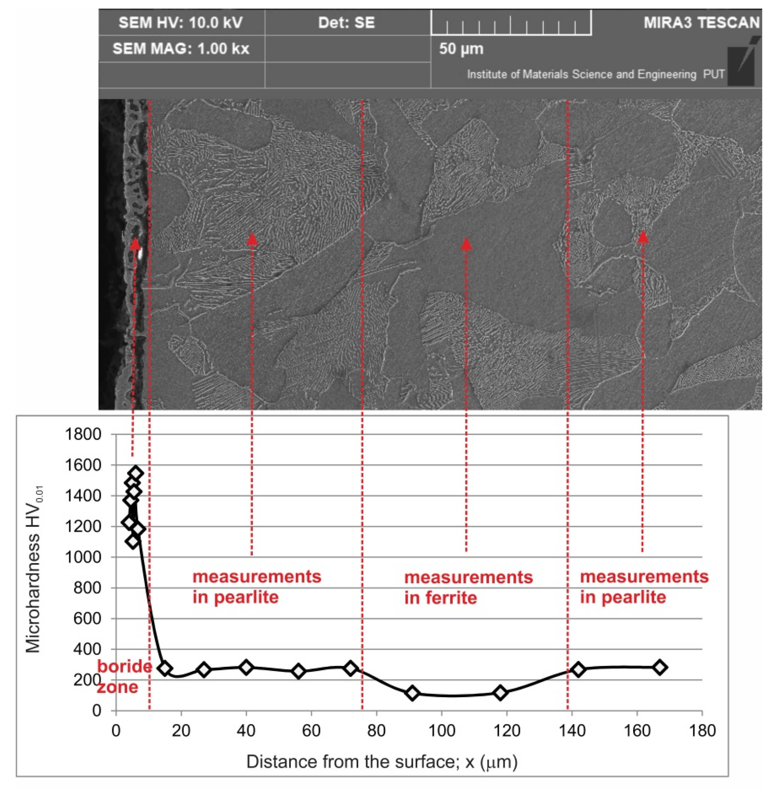
3.3. Microhardness and Wear Resistance

The microhardness measurements were performed on the cross-section of Armco iron after simultaneous gas borocarburizing in N2–H2–B(CH3O)3 atmosphere at 1223 K (950 °C) for 2 h. The results of hardness tests as well as the corresponding SEM image with the selected areas of the areas of measurements are presented in Figure 6. The highest hardness, ranging from 1103 HV0.01 to 1546 HV0.01, was obtained in the iron boride zone, in which the Fe2B phase was identified. These values were slightly lower in comparison with those reported in literature data [20,26]. The reason for diminished hardness could be the presence of porosity in the boride layer. Below the boride zone, the zone of carbon diffusion was formed as a result of the process of carburizing. In this zone, the highest hardness was measured in pearlite grains (about 270 HV0.01). Simultaneously, if indentation was performed in the ferrite grains, the hardness decreased to about 115 HV0.01.
The wear resistance test was performed for gas borocarburized Armco iron in N2–-H2–B(CH3O)3 atmosphere at 1223 K (950 °C) for 2 h. In order to estimate the influence of this process on wear resistance of Armco iron, the results were compared to the tribological properties of untreated Armco iron. The mass loss of both samples per unit of friction surface vs. time of friction is presented in Figure 7. The values of mass wear intensity factor Imw are also presented. A significantly lower value of Imw was calculated for gas borocarburized sample and was equal to 0.845 mg·cm−2·h−1. A more intensive wear was characteristic of untreated Armco iron (Imw = 2.056 mg·cm−2·h−1). Taking the mass loss Δm into consideration, it should be noted that a higher value was measured for the untreated sample (Δm = 38.79 mg). The presence of the Fe2B layer on the outer surface of the sample caused a reduction in mass loss to a value of 11.37 mg. Simultaneously, the comparison of relative mass loss Δm/mi indicated that gas borocarburizing in a N2–H2–B(CH3O)3 atmosphere resulted in a decrease of this ratio from 0.00215 (for untreated Armco iron) to 0.000625 (for borocarburized Armco iron). Evaluation by the mass wear intensity factor and relative mass loss confirmed the advantageous influence of simultaneous gas borocarburizing in N2–H2–B(CH3O)3 atmosphere on the wear resistance of Armco iron.
The observation of a worn surface after the test performed for untreated Armco iron indicated strong plastic deformations (Figure 8) as a result of low hardness of this material. During the analysis of EDS patterns, the main elements of the counter-specimen (Co, W, Nb) were also taken into account. Relatively high concentrations of these elements were detected on the worn surface of untreated Armco iron. Probably, it indicates adhesive wear. During the wear test, the increased temperature at the contact of the friction pair created favorable conditions for adhesion. For this reason, the relatively less mass loss of the Armco iron was measured after the wear test. It could be also observed that a high concentration of oxygen was characteristic for Armco iron after the wear test. The increased temperature of the contact area between specimen and counter-specimen could be the reason for the appearance of iron oxides on the worn surface of the specimen. It could indicate possible oxidative wear.
The worn surface of counter-specimen (S20S) after the wear test of untreated Armco iron is shown in Figure 9. As a consequence of the high hardness of sintered carbide S20S, this material was not prone to plastic deformation. Characteristic shallow grooves appeared on the worn surface of the counter-specimen. They confirmed intensive abrasive wear as the main wear mechanism. The analysis of EDS patterns in Figure 9 could lead to the conclusion that the worn surface of the counter-specimen was free from adhesion symptoms. However, in some areas increased iron and oxygen concentrations were detected. This indicated the presence of iron oxides. Probably, during the wear test, iron oxides were formed on the surface of untreated Armco iron, and the small debris of oxides could be reattached from the specimen to the counter-specimen surface. This confirmed the possibility of oxidative wear.
The worn surface, observed after the wear test, showed intensive abrasive wear on the surface of the gas borocarburized layer (Figure 10). No signs of plastic deformation and adhesion were visible on the worn surface of the gas borocarburized specimen. Only shallow grooves appeared on the worn surface. The analysis of EDS patterns was performed taking into account the main elements of the counter-specimen (Co, W, Nb). Very low concentrations of these elements were detected on the worn surface of gas borocarburized Armco iron which indicated the absence of an adhesive mechanism for wear. As a consequence of increased contact temperature between the specimen and counter-specimen, in several areas iron oxides were formed. This was confirmed by increased concentration of oxygen in these regions of the worn surface (Figure 10).
The worn surface of the counter-specimen (sintered carbide S20S) was free from plastic deformations (Figure 11). The clearly visible grooves confirmed abrasive wear as a predominant wear mechanism. However, in some areas relatively high concentrations of iron and oxygen were observed which could indicate that the iron oxides were reattached from the borocarburized specimen to the counter-specimen surface. Hence, the wear mechanism also covered oxidative wear.

4. Conclusions

The use of the typical boron halides (e.g., BCl3, BF3) as a boron source during gas boriding has been problematic mainly because of the toxic character of these agents. The main scientific objective of this investigation was the determination of the possibility of the formation of a boride layer by a gaseous process using an unconventional boron source, which would be non-toxic in comparison with the boron halides. The common use of organic compounds as a boron source in plasma-assisted processes was the instigation to analyze the possibility of applying such boron sources during the typical gas process of thermochemical treatment. Therefore, in the present study trimethyl borate was used as the boron source for the diffusion process. The application ofa N2–H2–B(CH3O)3 atmosphere enabled the simultaneous gas carburizing and boriding of Armco iron. Such a process, called simultaneous gas borocarburizing, was carried out at 1223 K (950 °C) for 2 h. The most important results were as follows:
-
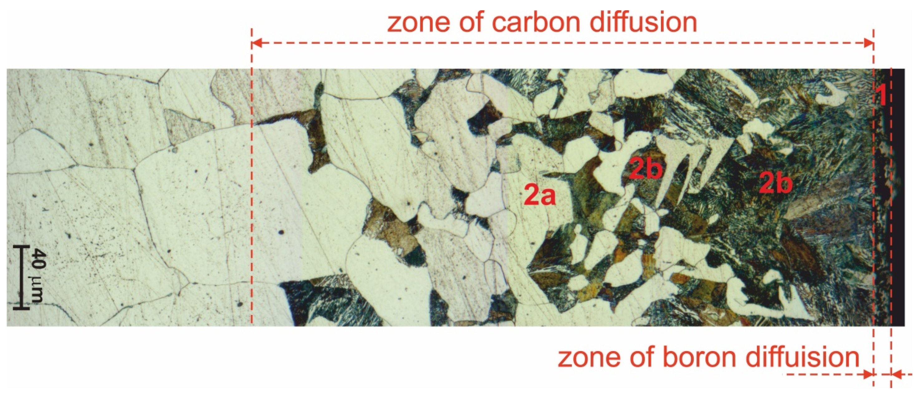
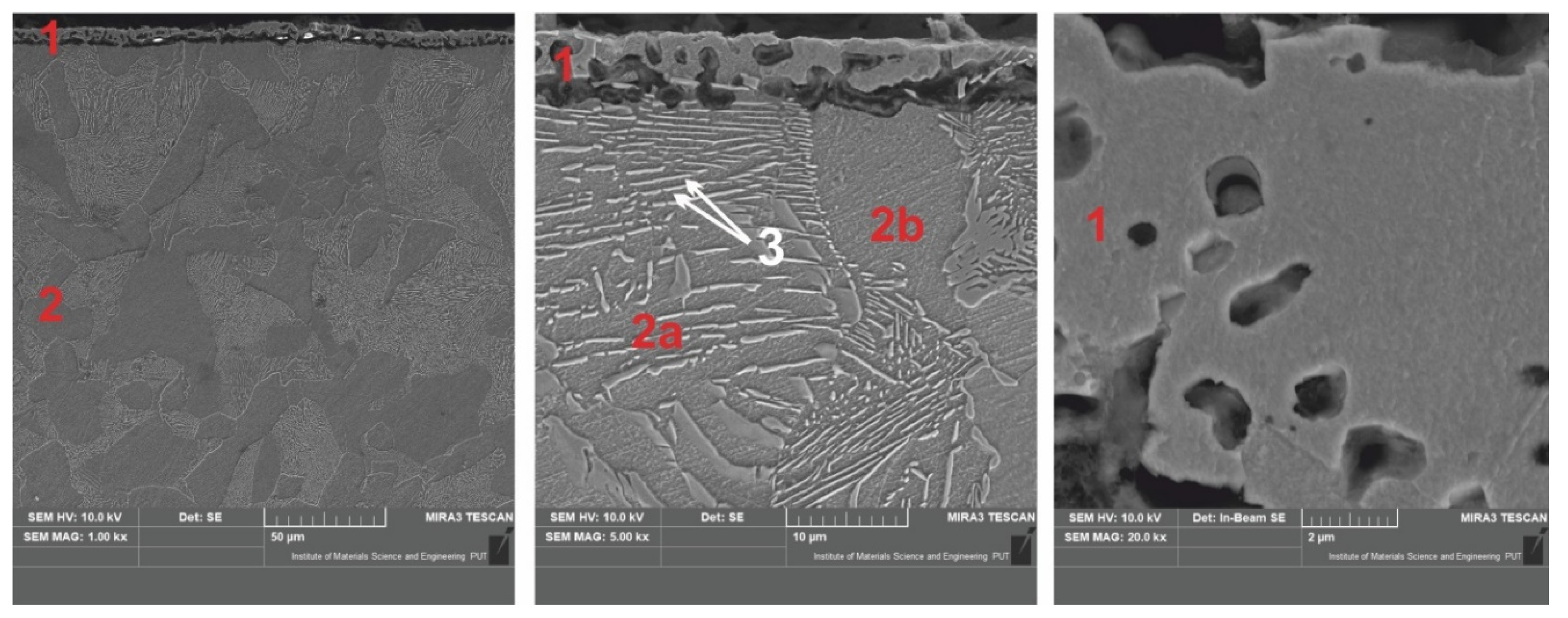
The microstructure of the produced diffusion layer consisted of two zones: an outer zone of Fe2B iron borides and an inner zone of carbon diffusion (carburized zone),
-
The important reaction, proceeding during simultaneous gas borocarburizing with the use of trimethyl borate, was the reduction of trimethyl borate with hydrogen. As a consequence, atomic carbon was produced. Therefore, the appropriate conditions for a carburizing process were realised. The next reaction in this atmosphere provided atomic boron, which could diffuse into the substrate material producing the boride layer,
-
The compact boride zone was characterized by low thickness (average value of 7.8 µm) which was caused by the hindered diffusion of boron atoms into the carburized zone,
-
Simultaneously formed, due to the intensive carburizing—the zone of carbon diffusion was characterized by a considerable thickness of 396.7 µm,
-
The presence of the outer Fe2B zone caused an increase in hardness up to 1546 HV0.01,
-
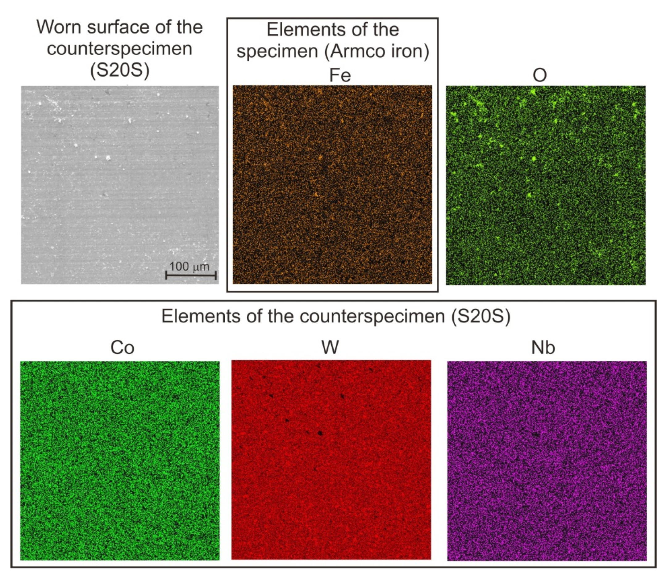
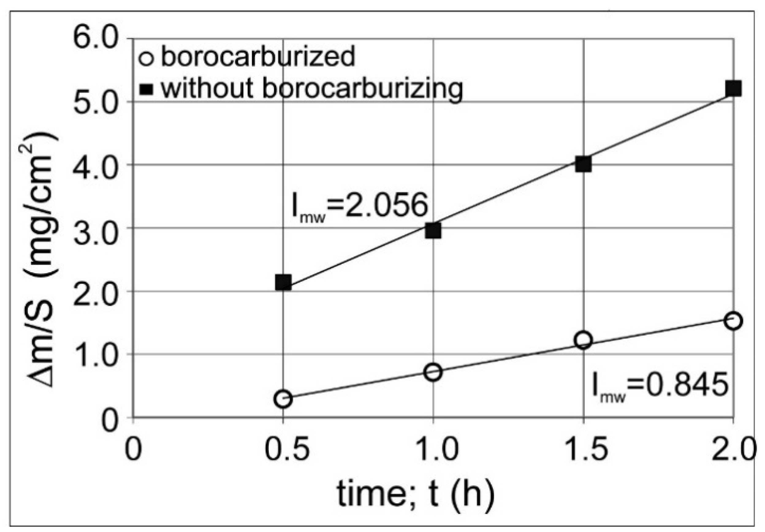
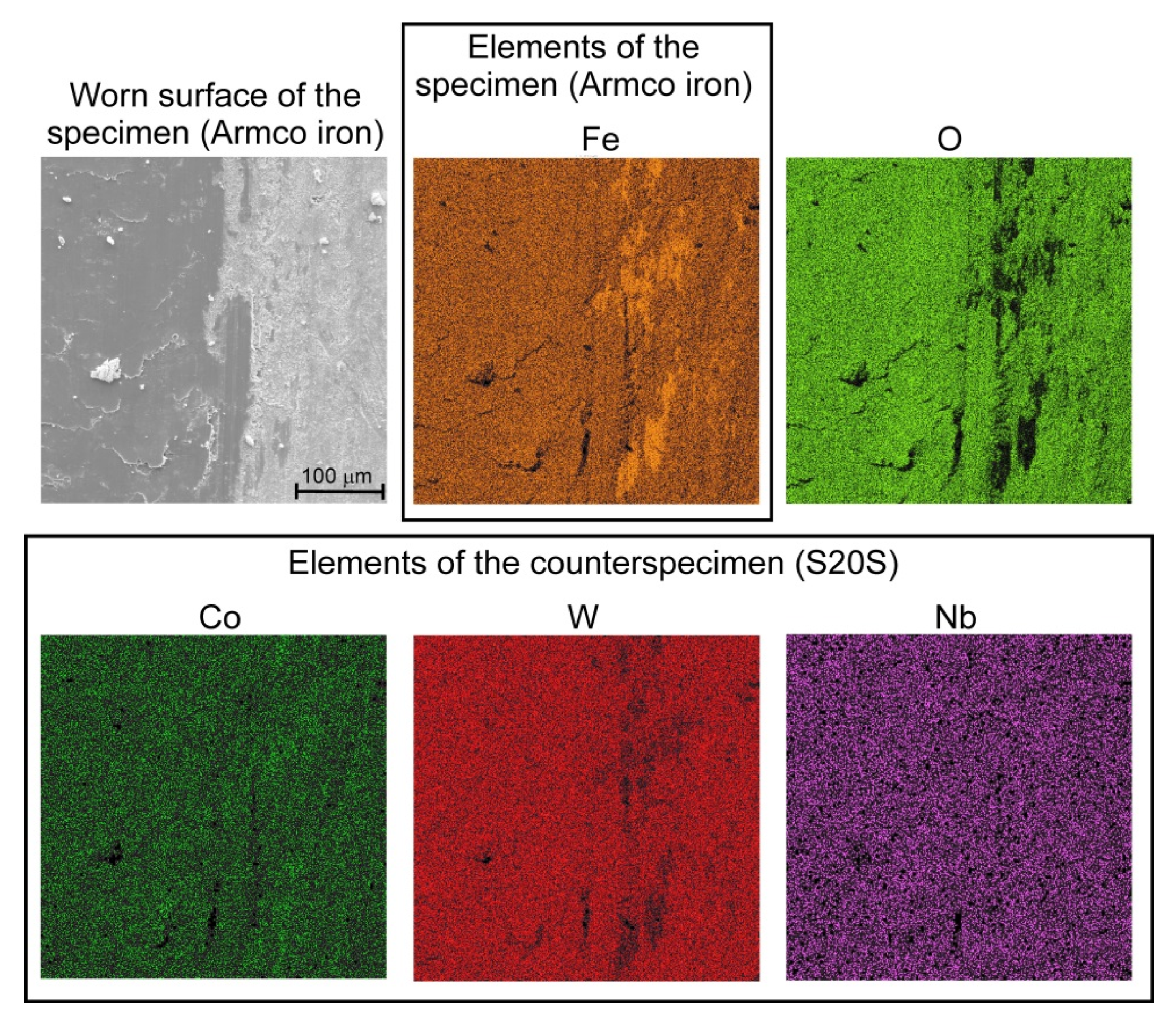
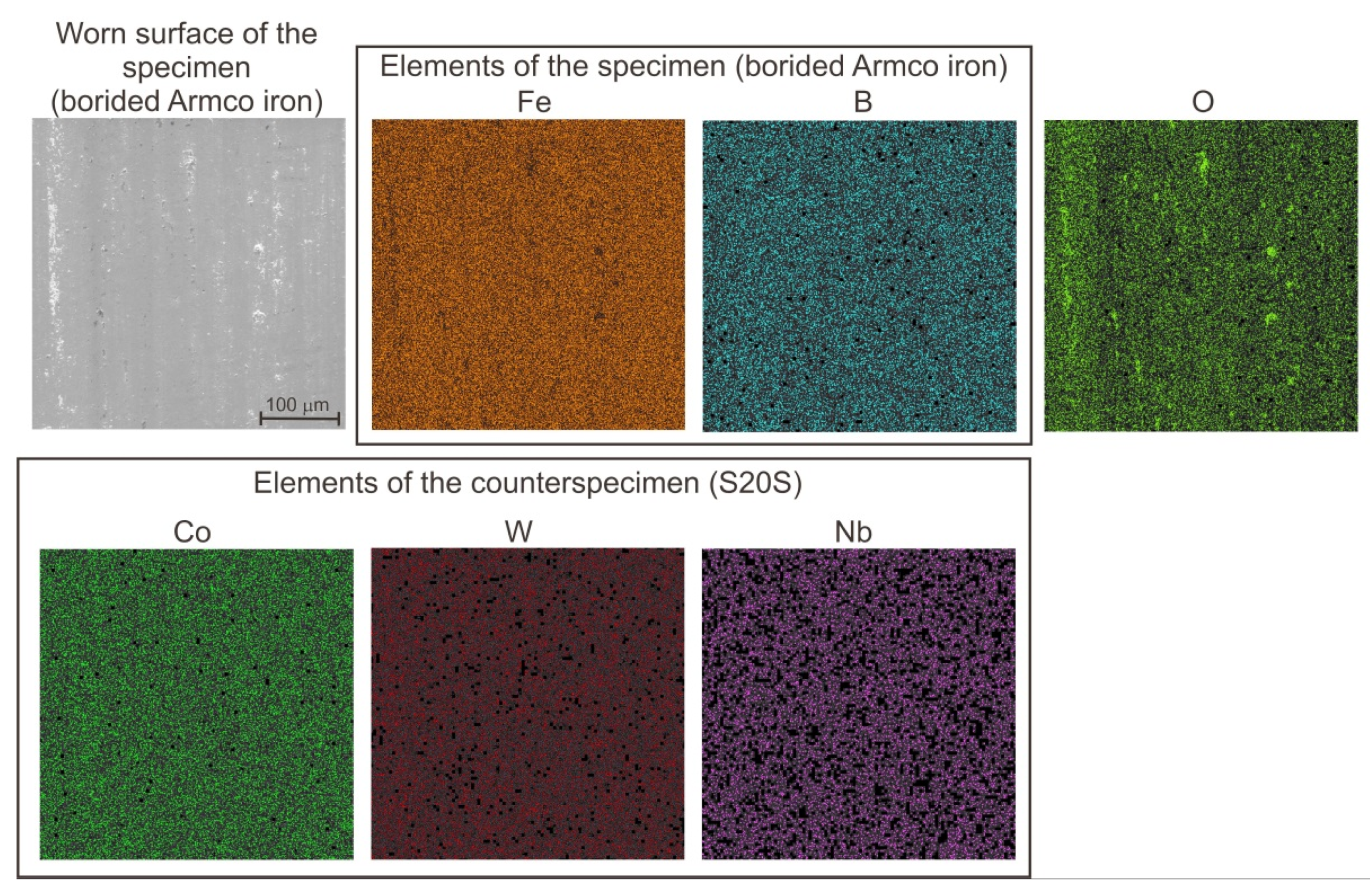
Gas borocarburizing in a N2–H2–B(CH3O)3 atmosphere caused an increase in the wear resistance in comparison with untreated Armco iron.
The obtained results indicated the possibility of the application of trimethyl borate B(CH3O)3 as a boron precursor for gas borocarburizing. However, there are still some problems with technical realization of the process, if trimethyl borate is used as a boron source. For example, it will be necessary to improve the method of delivery of B(CH3O)3 to the retort, because the carrying gas was here colder than the vapors of trimethyl borate. This situation caused unstable delivery of the boron source to the retort because of the condensation of B(CH3O)3 vapors in the delivery conduit.

Author Contributions

Conceptualization, N.M. and M.K.; Methodology, N.M., P.D. and M.K.; Validation, N.M., P.D. and M.K.; Formal Analysis, N.M. and P.D.; Investigation, N.M. and P.D.; Resources, N.M., P.D. and M.K.; Data Curation, N.M. and P.D.; Writing-Original Draft Preparation, N.M.; Writing-Review & Editing, M.K.; Visualization, N.M., P.D. and M.K.; Supervision, M.K.; Project Administration, N.M.; Funding Acquisition, N.M. All authors have read and agreed to the published version of the manuscript.

Funding

This research was funded by the National Science Centre in Poland grant number UMO-2016/23/D/ST8/02697.

Acknowledgments

The authors wish to thank Wojciech Gęstwa from the Institute of Materials Science and Engineering for his help and cooperation during the realization of this work.

Conflicts of Interest

The authors declare no conflict of interest.

References

  1. Kulka, M. Current Trends in Boriding: Techniques; Engineerings Materials series; Springer International Publishing, Springer Nature Switzerland AG: Basel, Switzerland, 2019; pp. 1–282. ISBN 978-3-030-06781-6. [Google Scholar]
  2. Asthana, P.; Liang, H.; Usta, M.; Ucisik, A.H. Wear and surface characterization of boronized pure Iron. J. Tribol. 2007, 129, 1–10. [Google Scholar] [CrossRef]
  3. Elias-Espinosa, M.; Ortiz-Dominguez, M.; Keddam, M.; Flores-Renteria, M.A.; Damian-Mejia, O.; Zuno-Silva, J.; Hernandez-Avila, J.; Cardoso-Legorreta, E.; Arenas-Flores, A. Growth kinetics of the Fe2B layers and adhesion on Armco iron substrate. J. Mater. Eng. Perform. 2014, 23, 2014–2943. [Google Scholar] [CrossRef]
  4. Venkataraman, B.; Sundararajan, G. The high speed sliding wear behaviour of boronized medium carbon steel. Surf. Coat. Technol. 1995, 73, 177–184. [Google Scholar] [CrossRef]
  5. Xu, C.H.; Xi, J.K.; Gao, W. Improving the mechanical properties of boronized layers by superplastic boronizing. J. Mater. Process. Technol. 1997, 65, 94–98. [Google Scholar] [CrossRef]
  6. Gutierrez-Noda, L.; Cuao-Moreu, C.A.; Perez-Acosta, O.; Lorenzo-Bonet, E.; Zambrano-Robledo, P.; Hernandez-Rodriguez, M.A.L. The effect of a boride diffusion layer on the tribological properties of AISI M2 steel. Wear 2019, 426–427, 1667–1671. [Google Scholar] [CrossRef]
  7. Hernandez-Sanchez, E.; Rodriguez-Castro, G.; Meneses-Amador, A.; Bravo-Barcenas, D.; Arzate-Vazquez, I.; Martinez-Gutierrez, H.; Romero-Romo, M.; Campos-Silva, I. Effect of the anisotropic growth on the fracture toughness measurements obtained in the Fe2B layer. Surf. Coat. Technol. 2013, 237, 292–298. [Google Scholar] [CrossRef]
  8. Spence, T.W.; Makhlouf, M.M. Characterization of the operative mechanism in potassium fluoborate activated pack boriding of steels. J. Mater. Process. Technol. 2005, 168, 127–136. [Google Scholar] [CrossRef]
  9. Meneses-Amador, A.; Blancas-Perez, D.; Corpus-Mejia, R.; Rodriguez-Castro, G.A.; Martinez-Trinidad, J.; Jimenez-Tinoco, L.F. Adhesive and cohesive strength in FeB/Fe2B systems. J. Mater. Eng. Perform. 2018, 27, 2018–2089. [Google Scholar] [CrossRef]
  10. Türkmen, I.; Yalamac, E.; Keddam, M. Investigation of tribological behaviour and diffusion model of Fe2B layer formed by pack-boriding on SAE 1020 steel. Surf. Coat. Technol. 2019, 377, 124888. [Google Scholar] [CrossRef]
  11. Türkmen, I.; Yalamac, E. Growth of the Fe2B layer on SAE 1020 steel employed a boron source of H3BO3 during the powder-pack boriding method. J. Alloys Compd. 2018, 744, 658–666. [Google Scholar] [CrossRef]
  12. Kartal, G.; Eryilmaz, O.L.; Krumdick, G.; Erdemir, A.; Timur, S. Kinetics of electrochemical boriding of low carbon steel. Appl. Surf. Sci. 2011, 257, 6928–6934. [Google Scholar] [CrossRef]
  13. Allaoui, O.; Bouaouadja, N.; Saindernan, G. Characterization of boronized layers on a XC38 steel. Surf. Coat. Technol. 2006, 201, 3475–3482. [Google Scholar] [CrossRef]
  14. Sen, S.; Sen, U.; Bindal, C. The growth kinetics of borides formed on boronized AISI 4140 steel. Vacuum 2005, 77, 195–202. [Google Scholar] [CrossRef]
  15. Sen, S.; Sen, U.; Bindal, C. An approach to kinetic study of borided steels. Surf. Coat. Technol. 2005, 191, 274–285. [Google Scholar] [CrossRef]
  16. Wierzchon, T.; Bielinski, P.; Sikorski, K. Formation and properties of multicomponent and composite borided layers on steel. Surf. Coat. Technol. 1995, 73, 121–124. [Google Scholar] [CrossRef]
  17. Hunger, H.J.; Löbig, G. Generation of boride layers on steel and nickel alloys by plasma activation of boron trifluoride. Thin Solid Films 1997, 310, 244–250. [Google Scholar] [CrossRef]
  18. Miyashita, F.; Yokota, K. Plasma-assisted low temperature boridation of pure iron and steels. Surf. Coat. Technol. 1996, 84, 334–337. [Google Scholar] [CrossRef]
  19. Rodriguez Cabeo, E.; Laudien, G.; Biemer, S.; Rie, K.T.; Hoppe, S. Plasma-assisted boriding of industrial components in a pulsed d.c. glow discharge. Surf. Coat. Technol. 1999, 116–119, 229–233. [Google Scholar] [CrossRef]
  20. Kashaev, N.; Stock, H.R.; Mayr, P. Plasmaborieren mit Triethylboran. Haerterei Tech. Mit. 2003, 58, 1–9. [Google Scholar]
  21. Qiao, X.; Stock, H.R.; Küper, A.; Jarms, C. Effects of B(CH3O)3 content on a PACVD plasma-boriding process. Surf. Coat. Technol. 2000, 131, 291–293. [Google Scholar] [CrossRef]
  22. Küper, A. Plasma-assisted boronizing. Adv. Mater. Process. 2003, 161, 20–22. [Google Scholar]
  23. Kulka, M.; Makuch, N.; Pertek, A. Microstructure and properties of laser-borided 41Cr4 steel. Opt. Laser Technol. 2013, 45, 308–318. [Google Scholar] [CrossRef]
  24. Kulka, M.; Mikolajczak, D.; Makuch, N.; Dziarski, P.; Miklaszewski, A. Wear resistance improvement of austenitic 316L steel by laser alloying with boron. Surf. Coat. Technol. 2016, 291, 292–313. [Google Scholar] [CrossRef]
  25. Sashank, S.; Dinesh Babu, P.; Marimuthu, P. Experimental studies of laser borided low alloy steel and optimization of parameters using response surface methodology. Surf. Coat. Technol. 2019, 363, 255–264. [Google Scholar] [CrossRef]
  26. Kulka, M.; Makuch, N.; Piasecki, A. Nanomechanical characterization and fracture toughness of FeB and Fe2B iron borides produced by gas boriding of Armco iron. Surf. Coat. Technol. 2017, 325, 515–532. [Google Scholar] [CrossRef]
  27. Kulka, M.; Makuch, N.; Pertek, A.; Małdziński, L. Simulation of the growth kinetics of boride layers formed on Fe during gas boriding in H2– BCl3 atmosphere. J. Solid State Chem. 2013, 199, 196–203. [Google Scholar] [CrossRef]
  28. Keddam, M.; Kulka, M.; Makuch, N.; Pertek, A.; Małdziński, L. A kinetic model for estimating the boron activation energies in the FeB and Fe2B layers during the gas-boriding of Armco iron: Effect of boride incubation times. Appl. Surf. Sci. 2014, 298, 155–163. [Google Scholar] [CrossRef]
  29. Pertek, A. The Structure Formation and the Properties of Boronized Layers Obtained in Gaseous Boriding Process; Dissertation No. 365; Publishing House of Poznan University of Technology: Poznan, Poland, 2001; pp. 1–194. [Google Scholar]
  30. Pertek, A.; Kulka, M. Two-step treatment carburizing followed by boriding on medium-carbon steel. Surf. Coat. Technol. 2003, 173, 309–314. [Google Scholar] [CrossRef]
  31. Kulka, M.; Pertek, A. Gradient formation of boride layers by borocarburizing. Appl. Surf. Sci. 2008, 254, 5281–5290. [Google Scholar] [CrossRef]
  32. Kulka, M.; Pertek, A.; Makuch, N. The importance of carbon concentration–depth profile beneath iron borides for low-cycle fatigue strength. Mater. Sci. Eng. A 2011, 528, 8641–8650. [Google Scholar] [CrossRef]
  33. Kulka, M.; Makuch, N.; Pertek, A.; Piasecki, A. An alternative method of gas boriding applied to the formation of borocarburized layer. Mater. Charact. 2012, 72, 59–67. [Google Scholar] [CrossRef]
  34. Kulka, M.; Makuch, N.; Dziarski, P.; Mikołajczak, D.; Przestacki, D. Gradient boride layers formed by diffusion carburizing and laser boriding. Opt. Lasers Eng. 2015, 67, 163–175. [Google Scholar] [CrossRef]
  35. Wang, B.; Xue, W.; Wu, J.; Jin, X.; Hua, M.; Wu, Z. Characterization of surface hardened layers on Q235 low-carbon steel treated by plasma electrolytic borocarburizing. J. Alloys Compd. 2013, 578, 162–169. [Google Scholar] [CrossRef]
  36. Wang, B.; Jin, X.; Xue, W.; Wu, Z.; Du, J.; Wu, J. High temperature tribological behaviors of plasma electrolytic borocarburized Q235 low-carbon steel. Surf. Coat. Technol. 2013, 232, 142–149. [Google Scholar] [CrossRef]
  37. Wang, B.; Xue, W.; Wu, Z.; Jin, X.; Wu, J.; Du, J. Influence of discharge time on properties of plasma electrolytic borocarburized layers on Q235 low-carbon steel. Mater. Chem. Phys. 2015, 168, 10–17. [Google Scholar] [CrossRef]
  38. Makuch, N.; Kulka, M. Microstructural characterization and some mechanical properties ofgas-borided Inconel 600-alloy. Appl. Surf. Sci. 2014, 314, 1007–1018. [Google Scholar] [CrossRef]
  39. Makuch, N.; Kulka, M.; Piasecki, A. The effects of chemical composition of Nimonic 80A-alloy on the microstructure and properties of gas-borided layer. Surf. Coat. Technol. 2015, 276, 440–455. [Google Scholar] [CrossRef]
  40. Balci, S.; Sezgi, N.; Eren, E. Boron oxide production kinetics using boric acid as raw material. Ind. Eng. Chem. Res. 2012, 51, 11091–11096. [Google Scholar] [CrossRef]
  41. Przybyłowicz, K. Teoria i Praktyka Borowania Stali (Theory and Practice of Steel Boronizing); PL ISSN 0239-4979; Publishing House of Kielce University of Technology: Kielce, Poland, 2000. (In Polish) [Google Scholar]
  42. Hirsch, T.; Hoffmann, F.; Mayr, P. Röntgenographische untersuchungen mikrostruktureller kenngrößen von verbindungsschichten gasnitrierter stähle. Haerterei Tech. Mit. 1996, 51, 390–398. (In German) [Google Scholar]
  43. Hirsch, T.; Hoffmann, F.; Mayr, P. Effect of different compound layer and base material microstructures on microstrain and domain size of nitrided steel. Surf. Eng. 1998, 14, 481–488. [Google Scholar] [CrossRef]
  44. Kraus, I.; Ganev, N.; Gosmanova, G.; Tietz, H.D.; Pfeiffer, L.; Böhm, S. Residual stress measurement in alumina coatings. Mater. Sci. Eng. A 1995, 199, L15–L17. [Google Scholar] [CrossRef]
Figure 1. The scheme of devices used for simultaneous gas borocarburizing in N2–H2–B(CH3O)3 atmosphere; 1—furnace; 2—cooling system; 3—quartz retort; 4—system of power supply and temperature control; 5—personal computer with HTMonit and DLM Simple version 1.0 software; 6—temperature measuring system; 7—vacuum pump; 8—gas scrubber; 9—water inlet; 10—water outlet; 11—control system of the B(CH3O)3 temperature; 12—rotameter; 13—pressure pickup; 14—vacuummeter; 15—heating device with sand bath; 16—cylinder with B(CH3O)3; 17—mass-flow meter; 18—cylinder with N2-H2 mixture; 19—cylinder with nitrogen.
Coatings 10 00564 g001
Figure 2. Scheme of trimethyl borate concentration: dependence of B(CH3O)3 content on temperature (a); contents of trimethyl borate in relation to H2 and in relation to the entire atmosphere during continuous gas borocarburizing in N2–H2–B(CH3O)3 atmosphere (b).
Coatings 10 00564 g002
Figure 3. Results of XRD analysis of gas borocarburized Armco iron and standard patterns for Fe2B, Feα and Fe3C.
Coatings 10 00564 g003
Figure 4. Optical microscope (OM) image of gas borocarburized Armco iron in N2–H2–B(CH3O)3 atmosphere at 1223 K (950 °C) for 2 h; 1—Fe2B iron borides, 2a—pearlite, 2b—ferrite.
Coatings 10 00564 g004
Figure 5. SEM images of gas borocarburized Armco iron in N2–H2–B(CH3O)3 atmosphere at 1223 K (950 °C) for 2 h; 1—iron borides zone, 2—carburized zone, 2a—pearlite, 2b—ferrite, 3—alternate lamellas of ferrite and cementite in pearlite.
Coatings 10 00564 g005
Figure 6. Microhardness profile of gas borided Armco iron in N2–H2–B(CH3O)3 atmosphere at 1223 K (950 °C) for 2 h and SEM image of selected areas of measurements.
Coatings 10 00564 g006
Figure 7. The results of wear resistance tests performed for gas borocarburized Armco iron in N2–H2–B(CH3O)3 atmosphere at 1223 K (950 °C) for 2 h and untreated Armco iron (without borocarburizing).
Coatings 10 00564 g007
Figure 8. The worn surface and EDS patterns of untreated Armco iron.
Coatings 10 00564 g008
Figure 9. The worn surface and EDS pattern of counter-specimen (S20S) after wear test of untreated Armco iron.
Coatings 10 00564 g009
Figure 10. The worn surface and EDS pattern of gas borocarburized Armco iron.
Coatings 10 00564 g010
Figure 11. The worn surface and EDS pattern of counter-specimen (S20S) after wear test of gas borocarburized Armco iron.
Coatings 10 00564 g011
Table 1. The nominal composition of Armco iron.
ElementCMnSiCrPSNiCuFe
(wt %)0.0350.200.220.100.0250.0250.120.10balance

