Article

Enhanced Tribological Properties of LA43M Magnesium Alloy by Ni60 Coating via Ultra-High-Speed Laser Cladding

1
State Key Laboratory for Mechanical Behavior of Materials, School of Materials Science and Engineering, Xi’an Jiaotong University, Xi’an 710049, China
2
Department of Materials Science & Engineering, Institute of Space Technology, Islamabad 44000, Pakistan
3
Tianjin Key Laboratory of High Speed Cutting & Precision Machining, Tianjin University of Technology and Education, Tianjin 300222, China
*
Author to whom correspondence should be addressed.
Coatings 2020, 10(7), 638; https://doi.org/10.3390/coatings10070638
Submission received: 10 June 2020 / Revised: 25 June 2020 / Accepted: 29 June 2020 / Published: 30 June 2020

Abstract

:
Laser modification techniques have been widely adopted in the field of surface engineering. Among these modified techniques, ultra-high-speed laser cladding is trending most nowadays to fabricate wear-resistant surfaces. The main purpose of this research is to provide a detailed insight of ultra-high-speed laser cladding of hard Ni60 alloy on LA43M magnesium alloy to enhance its surface mechanical properties. Multiple processing parameters were investigated to obtain the optimal result. The synthesized coating was studied microstructurally by field emission scanning electron microscopy (FESEM) equipped with an energy dispersive spectrometer (EDS) and X-ray diffraction (XRD). The microhardness and wear resistance of the Ni60 coating were analyzed under Vickers hardness and pin on disc tribometer respectively. The obtained results show that the dense Ni60 coating was fabricated with a thickness of 300 μm. No cracks and porosities were detected in cross-sectional morphology. The Ni60 coating was mainly composed of γ-Ni and hard phases (chromium carbides and borides). The average microhardness of coating was recorded as 948 HV0.3, which is approximately eight times higher than that of the substrate. Meanwhile, the Ni60 coating exhibited better wear resistance than the substrate, which was validated upon the wear loss and wear mechanism. The wear loss recorded for the substrate was 6.5 times higher than that of the coating. The main wear mechanism in the Ni60 coating was adhesive while the substrate showed abrasive characteristics.

1. Introduction

Lightweight materials play a vital role towards different commercial and noncommercial applications from an economic perspective. Magnesium-based alloys with lithium as the major alloying element are known as ultralight metallic structural materials. These alloys, in comparison with other materials, have significant low density of 1.25–1.65 g/cm3, which is almost 50% of aluminum alloys and 75% of other magnesium alloys [1]. Magnesium lithium alloys are always considered a prime choice for applications in the aviation, aerospace, defense and 3C industries, because of their high stiffness, good magnetic shielding, high specific strength and damping capacity [2,3]. Being capable of very high potential use, these alloys nowadays have attracted more attention in electrochemical power, biomedicine and other civilian fields [4,5]. However, their poor tribological properties greatly affected their popularity and reduced usage in different applications.
At present, to expand the industrial applications of these alloys, it is necessary and efficient to apply multiple surface modification techniques to alter their surface properties. There are multiple advance surface modification techniques which have been adopted by number of researchers to improve the surface properties of magnesium alloys, such as physical vapor deposition (PVD) [6,7], chemical vapor deposition (CVD) [8], electroplating [9], electroless plating [10], diffusion treatment [11], high-velocity oxy fuel thermal spray [12,13,14], cold spray [15] and many others. But most of the surface modification techniques possess poor bond strength ratio, which ultimately reduces its performance in aggressive and harsh environments, while the efficiency for coating preparation is relatively low as well.
At the beginning of the 1980s, the conventional overlay laser cladding technique was proposed, which involved rapid heating and nonequilibrium solidification that produces dense and porosity-free coatings. These coatings undergo marginal distortion, low heat affecting of substrate and metallurgical bonding between substrate and clad layers [16,17,18].This technique results in high compactness along with remarkable physical and chemical performance [19,20,21]. However, there are several drawbacks which are associated with this conventional process which confines its operational use. For example, the higher difference in melting temperature of cladding powder and substrate requires an extensive amount of heat input, which not only affects the dimensional accuracy of the substrate but also produces a higher heat affected zone (HAZ). Furthermore, dilution rate is usually high because of low linear velocity and most of the laser energy was absorbed by the substrate, hence producing larger dilution which ultimately restricts its applications in thin components.
To overcome drawbacks of the conventional laser cladding process, Schopphoven et al [22] in 2016 proposed a novel technology, “ultra-high-speed laser deposition”, that can work more precisely and approximately 10 times faster in comparison with the conventional process. This process utilizes a high-intensity laser beam to heat and melt feeding powder before injecting into the molten pool of substrate to generate strong metallurgical bonding between clad layers and substrate. Coatings with thickness ranging from 25 to 400 µm with powder utilization efficiency greater than 85% can be achieved by this technology. Because of the very high deposition speed, a very limited amount of laser energy transfers to the substrate, hence a very small HAZ and the dilution rate can be retained even lower than 1% as most of the laser energy is absorbed by the powder. Lou et al. [23] successfully deposited FeCr alloy coating on 304 stainless steel with dilution rate less than 2% at a linear velocity of 147 mm/s. Li et al. [24] fabricated a 250 µm-thick high-quality 431 steel coating on 27SiMn substrate with cladding speed of 150 m/min and dilution rate calculated as less than 4%. Hence this novel ultra-high-speed cladding process provides a modern and reliable path to successfully deposit low-diluted, thin and high-quality protective coatings on magnesium-based alloys.
Searching for an available cladded alloy powder that suits perfectly the efficient laser cladding technique, nickel-based alloy powders were found best to fulfill the desired properties. Nickel as the solid solution along with other alloying elements can form multiple stable compounds. Among those compounds, some of them cause phase strengthening, which is very beneficial for achieving high temperature hardness [25,26]. Furthermore, nickel can also reduce the phase transformation temperature and thus be very advantageous for grain refinement purposes [27]. Nowadays, nickel-based self-fluxing alloy powder is catching the attention of a multitude of investigators and a number of intensive researches [28,29,30,31,32] have already been carried out to successfully fabricate wear-resistant surfaces for harsh and aggressive environments.
In the present research work, an attempt has been made to enhance the tribological properties of LA43M magnesium alloy for different applications. Hard Ni60 alloy powder was successfully cladded on LA43M magnesium alloy by a newly developed ultra-high-speed laser cladding technique. The advanced characterization techniques were utilized in order to investigate the microstructure, phase composition, micro-Vickers hardness and tribological properties in a very systematic manner to provide a comprehensive evaluation.

2. Materials and Experimental Procedures

2.1. Materials Selection

Commercial-grade hard Ni60 alloy powder (Kennametal Inc., Pittsburgh, PA, USA) was used to perform the subsequent ultra-high-speed laser cladding process. Figure 1 shows the size, shape and distribution of the powder. The substrate used was a 100 mm-long pipe-shaped LA43M magnesium alloy having diameter and thickness of 33 mm and 5 mm respectively. Prior to ultra-high-speed laser cladding, the feeding powder was dried in the oven for 45 min at 100 °C to prevent any kind of agglomeration that may cause blockage in powder supply. Meanwhile, the substrate was ground by using 240-grit SiC sandpaper, ultrasonically cleaned with ethanol and dried in air to improve adhesive strength between the coating and substrate workpiece. The chemical composition for feeding powder and substrate (wt.%) is given in Table 1.

2.2. Coating Deposition

Ultra-high-speed laser cladding coatings were fabricated by mean of IPG laser (model YLR-4000-KC, Oxford, MA, USA) operated in continuous mode with maximum laser power of 4.0 kW. The powder was injected into a laser molten pool with coaxial powder feeder nozzle driven by N2 gas. Since the laser cladding process is thermal in nature, so water was continually flowing through the substrate pipe while performing the process so that cooling effect provided by the continuous water stream suppressed the thermal effect which resisted against growing the HAZ of the substrate and can be reduced to its greater extent. The experiment was carried out in a protective chamber where a stream of argon as shielding gas was continually supplied at a flow rate of 10 L/min to prevent oxidation of the molten metal region.

2.3. Optimization of Cladding Process

To ensure the better tribological performance, the achieved coating must be dense and defect-free. The defect-free coatings can be achieved by properly controlling process parameters such as laser power, powder feeding rate, cladding speed, and beam focal positions, which have vital influence on the thickness of the coating layer, microstructural uniformity, dilution rate and HAZ [33,34,35]. In this study, one of the big challenges was the difference between the melting and boiling temperature of the feeding powder and substrate, so there was a possibility of discontinuity in the coating, i.e., pores, crack formation etc. Multiple variations in processing parameters (laser power, laser beam focal position, and cladding speed) were carried out to obtain the optimal. All variations in these parameters correspond to attain a dense, uniform and flawless coating. For example, high laser power results in crater formation, while at low laser power insufficient melting appeared. Secondly, the optimized laser focus position was measured, as, in some coatings, negative and positive defocus conditions were found. The negative defocus conditions were causing insufficient melting of feeding powder while positive defocus conditions were leading to higher dilution rate. Thirdly, coatings achieved at lower cladding speed had a higher heat affected zone as magnesium has a low melting temperature while Ni60 has very high melting temperature and required high heat input. All the parameters were taken under consideration simultaneously to achieve the high-quality coating that had better tribological performance. The optimal cladding process parameters for fabricating multiple track coatings on substrate are reported in Table 2. Subsequent to the laser cladding process, the electrical-discharge cutting machine was used for cutting the specimens for characterization and analysis. The impact of machine marks was eliminated using silicon-carbide-impregnated emery paper from 240 to 2000 grit mesh size in the transverse direction and finally polished with diamond paste. Figure 2 shows schematic illustration of the ultra-high-speed laser cladding process.

2.4. Characterizations

The phase analysis of synthesized coating was investigated by using the Shimadzu X-ray Diffractometer (XRD-6100, Kyoto, Japan) with Cu Kα radiations. The XRD spectra was obtained at an accelerating voltage of 40 kV and current 30 mA in the 2θ scanning range of 20–80°. The scans were performed with 4°/min step size. The microstructures along the cross section of clad specimens were studied using scanning electron microscopy (SEM, MIRA3 LMH, TESCAN, Brno, Czech Republic) equipped with energy dispersive spectroscopy (EDS).
The microhardness of coated specimens was performed using a Vickers microhardness tester (HXD-1000 TMC, Shanghai Taiming Optics Ltd., Shanghai, China) to measure the cross-sectional hardness of coatings. The selected test load was 0.3 kgf and dwell time was set to 15 s. The vertical profile from cladded region to the LA43M alloy substrate was acquired. A minimum of three adjacent indents were performed and the average value was recorded.
The wear properties of the cladded specimen were investigated using the dry sliding wear test. The sliding tests were conducted using the pin-on-disc tribometer on CFT-1 material surface comprehensive performance tester (Lanzhou Zhongke Kaihua Technology Development Co., Ltd., Lanzhou, China) at room temperature performed under dry sliding wearing conditions. The discs were the substrate and coated specimen and were polished, ultrasonically cleaned and, finally, dried. The pin used was Si3N4 ceramic (ball) having diameter of 6mm. The tests were conducted under constant load of 10 N at rotational speed of 200 rpm of the specimens. The wear loss of specimens was measured using an electric balance with a sensitivity of 10−4 g. The three-dimensional surface morphology of samples after wear test were evaluated by violet laser color 3d laser scanning microscope (VK-9710, KEYENCE, Tokyo, Japan).

3. Results and Discussions

3.1. Microstructure

Figure 3a shows cross sectioned microstructural evolution of Ni60 coated specimen. To elaborate the discussion, the coated specimen was divided into three distinct regions: (1) a fully dense cladded coated region of Ni60 alloy with average thickness range between 260 to 300 µm, (2) a transition region lying beneath the dense Ni60 layer containing grain structure evolution and (3) a LA43M substrate region. The dense coated region was free of cracks and sizeable pores. At higher magnification, as shown in Figure 3b, epitaxial growth of the magnesium cellular structure observed at the melting boundary of the LA43M substrate, which shows that the bond formed at the interface is metallurgical in nature.
Closer examination of the cross-section of the cladded specimen at its transition zone shows that it is composed of a mixture of magnesium matrix, interdendritic phases and partially melted Ni60 alloy powder. During powder feeding, many of the powder particles interact with each other and, because of such interaction, some particles fall directly into the molten pool rather than getting melted under the laser beam. Since the melting temperature of Ni60 particles is very high, low temperature in molten pool causes powder to undergo partial melting instead of full melting. During the laser cladding process, a small portion of substrate surface melts and generates a melt pool where interdiffusion starts taking place between the cladding powder and substrate. Figure 3b–d reflects the magnified cross-section SEM morphologies of the transition layer as labelled in Figure 3a. “B1”, “B2” and “B3” are the bottom, middle and top regions of transitional layer. These magnified images show microstructural evolution from substrate surface to the coating which consists of a combination of cellular and dendritic structure with observable grain refinement. At the bottom of the transition region, the solid solution phase of magnesium in the form of epitaxial cellular crystal growth was observed near the substrate surface, as shown in (Figure 3b. The mean cell arm spacing in this region was about 4–6 µm. As we move from the bottom of the transition layer to the middle region as shown in (Figure 3c the magnesium phases were observed in columnar form and cell spacing among these columnar crystals reduces to 2–4 µm. The reduction in cell spacing was recorded because of the increase in crystal growth velocity (from zero to maximum value) during solidification from the bottom to the upper region. At a further distance from these crystals, these cellular crystal magnesium phases change their morphology to dendritic form (Figure 3d), which happened because of solutes which pile up before solidification occurs, hence results in constitutional undercooling [16]. Therefore, it can be concluded that such a transition in structural morphologies happens because of the different cooling rate during the solidification process. Similar microstructural evolution in the transition region has been reported by an earlier study [36]. Meanwhile Figure 3e shows the microstructure of the Ni60 coating, which exhibits typical dendritic structure.

3.2. Phases

XRD analysis was carried out for identification of different phases present in the microstructure of the Ni60 coating. According to the XRD pattern shown in Figure 4. γ-Ni, CrB, FeNi3, Cr7C3, Fe31Si12 and Ni3B are the main phases present in the Ni60 coating. Meanwhile, no additional oxides were identified in XRD spectra, which was mainly because of protection provided by the shielding gas. However, instant melting and solidification during the cladding process resulted in saturation and lattices distortion, which gave rise to multiple distorted peaks which were very close to each other and could not be identified properly.
From color and morphological observations in contrast, shown in the inset of Figure 3e, it could be seen that the fully dense Ni60 coating was composed of a mixture of two distinct phases, a light gray region (A1) and a dark gray region (A2). According to the results revealed by the EDS area scan (reported in Table 3), A1 consisted of a higher quantity of carbon, chromium and silicon, whereas A2 had higher iron and nickel contents. In accordance with XRD pattern and EDS area scan, it can be inferred that area A1 mainly comprises of Cr7C3, CrB and Ni31Si12 whereas A2 contains FeNi3/Fe31Si12 eutectic and γ-Ni solid solution. Thus, the surface morphology of Ni60 coating can be concluded as hard chromium carbides and boride particles are uniformly embedded in the skeleton of the nickel-enriched matrix.

3.3. Microhardness

Figure 5 reveals the average microhardness distribution curve of the cross-sectioned cladded specimen along the direction perpendicular to the interface between the coated surface and substrate. It can be noted that the profile shows a moderate decreasing trend from the surface of the Ni60 coating region to the LA43M substrate. The average micro hardness value for the cladding surface of Ni 60 was found to be approximately 948 HV0.3, which is about eight times that of the LA43M substrate. Such high hardness in the cladded specimen was recorded because of uniformly dispersed hard chromium boride and carbide phases distributed uniformly in the skeleton of the γ Ni solid solution [37]. These hard Cr carbide and boride phases give rise to the dispersion strengthening effect, which ultimately showed a higher value of hardness. Meanwhile lower hardness values were recorded in the transition region because of the presence of nickel-based phases and soft magnesium. Beyond this, the hardness distribution curve also reveals that the heat-affected zone is narrow, down to approximately 140 µm, as compared to conventional process that produces a HAZ of 200 µm [38]. One study shows that it is even higher than 300 µm [39] for a different magnesium alloy. Hence, it can be concluded that ultra-high-speed laser cladding is a promising technique in which a limited amount of laser energy transfer to the substrate restricts the thickness of the HAZ from growing while maintaining the dimensional accuracy of the substrate as well.

3.4. Tribological Tests

3.4.1. Friction of Coefficient

Dry sliding conditions at ambient room temperature were chosen to analyze the tribological performance of the Ni60 coating and substrate. Prior to the wear test, both specimens were polished to the same roughness and finally cleaned with acetone in an ultrasonic bath for 15 min. The wear test was performed for a duration of 30 min under a static load of 10 N. Figure 6 reveals results of the friction coefficient curves of both specimens and it can be clearly seen that the average friction coefficient for the substrate was about 0.7, whereas for the Ni60 coating it was calculated approximately to be 0.5. The reduction of the friction coefficient occurred because of a more uniform and finer microstructure of the Ni60 coating along with higher microhardness and high bearing capacity. The friction coefficient curve of the Ni60 coating didn’t show an extensive range of pulsation, which shows that the coating didn’t show severe wear failure during the entire friction test.

3.4.2. Wear Mass Loss

The wear weight loss of both coated and substrate samples were determined under dry sliding wear conditions. The results illustrated that the Ni60-coated specimen exhibited significantly lower weight loss as compared to the substrate specimen. The obtained weight loss for the LA43M substrate (2.413 × 10⁻³ grams) was about 6.5 times higher than that of the Ni60 coating (0.369 × 10⁻³ grams) which clearly indicates that the wear resistance of the coated specimen was much higher than the substrate. The low wear weight loss is more advantageous to reduce the micro cracks formation on the surface and lowers the chances of the formation of micropores [40]. The results recorded for the wear resistance of specimens are in accordance with the resembling microhardness values as reported in Figure 5. Since the microhardness of the Ni60 coating is much higher than that of the substrate and hard chromium carbides and borides phases which are uniformly distributed on the surface ultimately enhances its wear resistance.

3.4.3. Worn Track Topography and Wear Mechanism

For better understanding of the wear resistance of the specimens, the cross-sectional profile of wear tracks was measured by a color three-dimensional laser microscopic system, as described in Figure 7. Five different locations along each wear track were obtained to get the cross-sectional area of the wear track and the average value was reported to calculate the volume of the wear track. The average wear scar width and depth of the substrate and the Ni60 coating is shown in Figure 8. When comparing, it can be clearly seen that that wear scar depth and width for coated specimen is much shallower and narrower than that of the substrate specimen.
The wear volume loss and specific wear rate were calculated using the following equations [41]:
W v = t 6 b ( 3 t 2 + 4 b 2 ) 2 π r
W s = W v P · S
where W v is the wear volume, t and b are the wear scar depth and wear scar width of the wear tracks respectively, whereas r is the radius of wear tacks. W s refers to specific wear rate, whereas P and S are the applied load and sliding distance respectively. Table 4 shows results for wear volume loss of both specimens. The wear volume results attained for both specimens were in accordance with the wear depth and width of wear scars and thus it can be concluded that wear rate of the Ni60 coated specimen was much lower as compared to the substrate and the coated specimen showed better tribological properties at ambient room temperature under dry sliding conditions.
The wear mechanisms of the Ni60 coating and LA43M substrate were determined by field emission scanning electron microscopy after the wear test, as shown in Figure 9 and noteworthy metallographic alterations were observed. The worn surface of the substrate specimen shown in Figure 9a depicts that it experienced abrasive wear. The worn substrate surface primarily consists of deep plowed grooves, peeling-off and micro plowing during the wear test. Furthermore, very low surface hardness (reported in Figure 5) makes it very difficult to stand against the counterpart and thus resulted in undergoing plastic deformation. These observations made from the worn track are in agreement with the results of specific wear rate as reported in Table 4. The configuration of these deep plowed grooves and peeling-off can be caused by the stress concentration which occurred at surface of wear track due to the pressures between the applied load and tangential movement of the microconcaved shaped counterpart Si3N4 ball, which ultimately generated micro cracks. When microcracks get extended to a certain level, it results in plastic deformation and peeling-off occurred at the groove edges [42]. Meanwhile, Figure 9b shows the worn surface of the Ni60 coating and it can be clearly seen that it exhibits obvious adhesive characteristics. Only shallow plowing groove lines along with server delamination were observed. Hence it can be concluded that higher microhardness and uniformly dispersed hard chromium carbides and borides particles ultimately results in better wear performance of Ni60 coating in dry sliding conditions. However, a similar observation has also been reported in the studies of Wan et al. [29] and Yao et al. [30] that these dispersed hard particles in nickel-based coatings are the main reason for their superior tribological performance.

4. Conclusion

This study concluded that Ni60 coating was successfully fabricated on a LA43M magnesium alloy substrate by using ultra-high-speed laser cladding technique. The main findings of this work are as follows:
(1)
A hard Ni60 alloy coating was successfully achieved via an ultra-high-speed laser cladding technique with optimal process parameters;
(2)
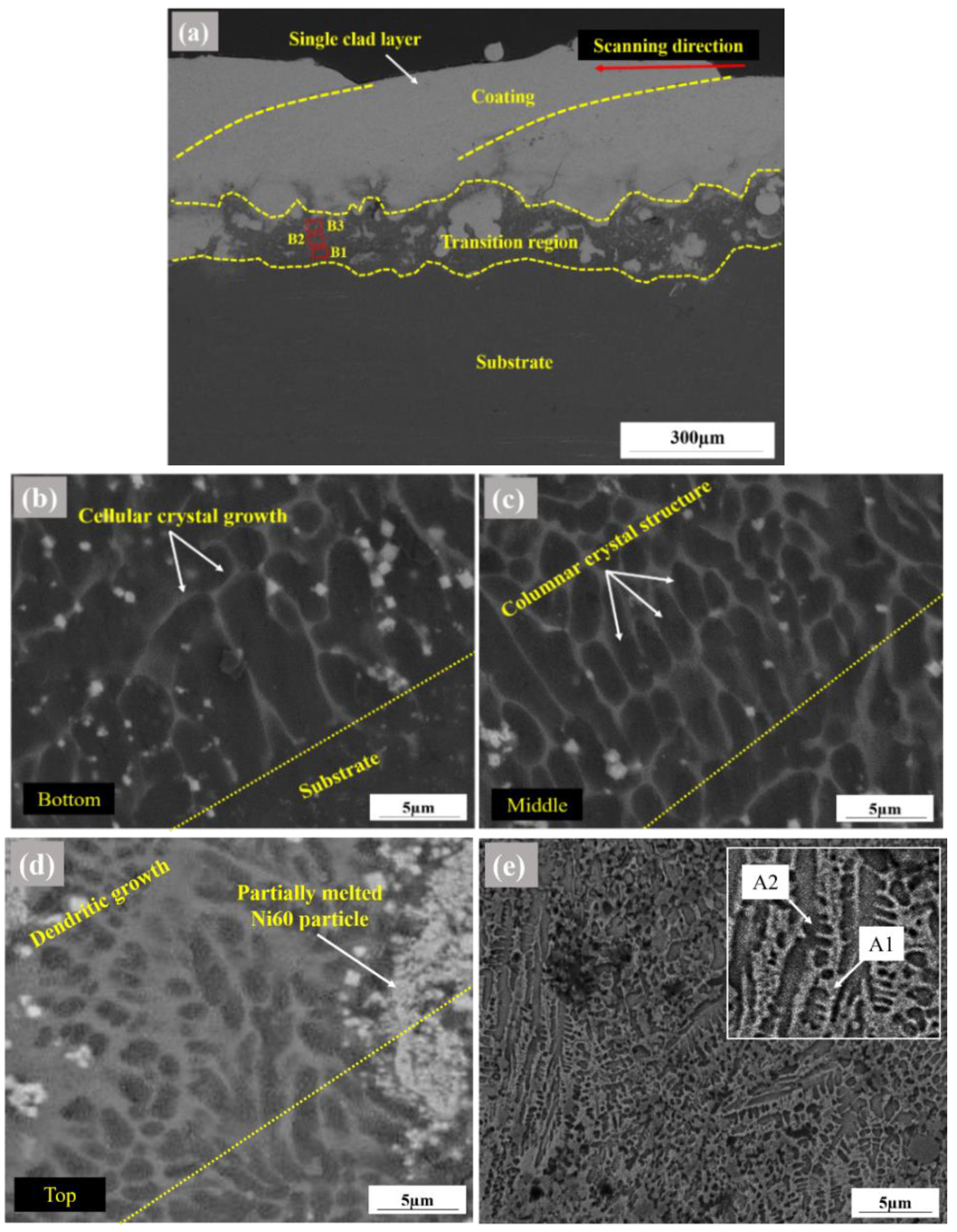
Microstructure analysis showed uniform and dense coating with thickness of about 300 µm was achieved. No obvious cracks and porosities were found. The Ni60 coating is mainly composed of γ-Ni solid solution and hard phases (chromium carbides and borides);
(3)
The hardness measurements obtained for Ni60 coating showed superior hardness value exceeding about eight times that of substrate hardness values. Hard chromium carbides and borides phases in coated region give rise to a solution strengthening effect which ultimately enhances the hardness of coating;
(4)
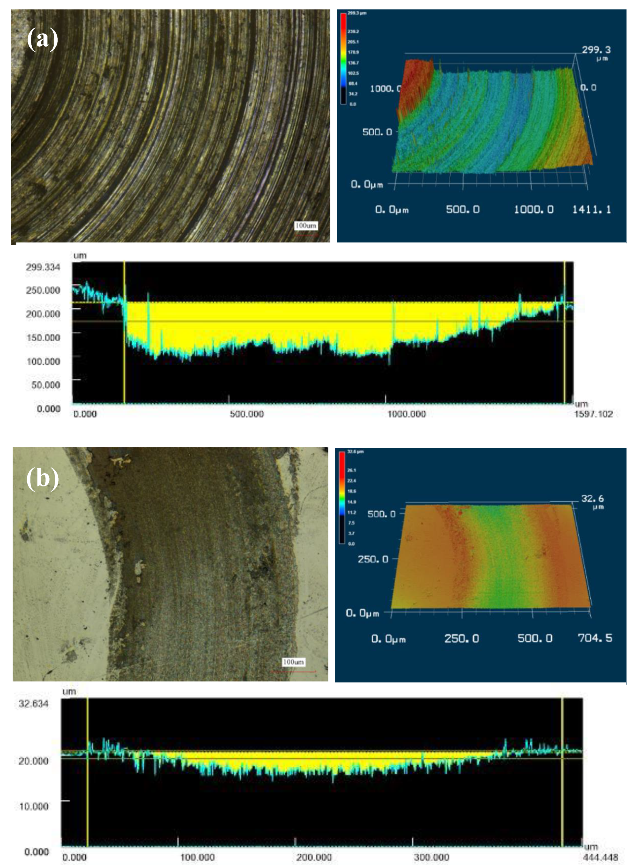
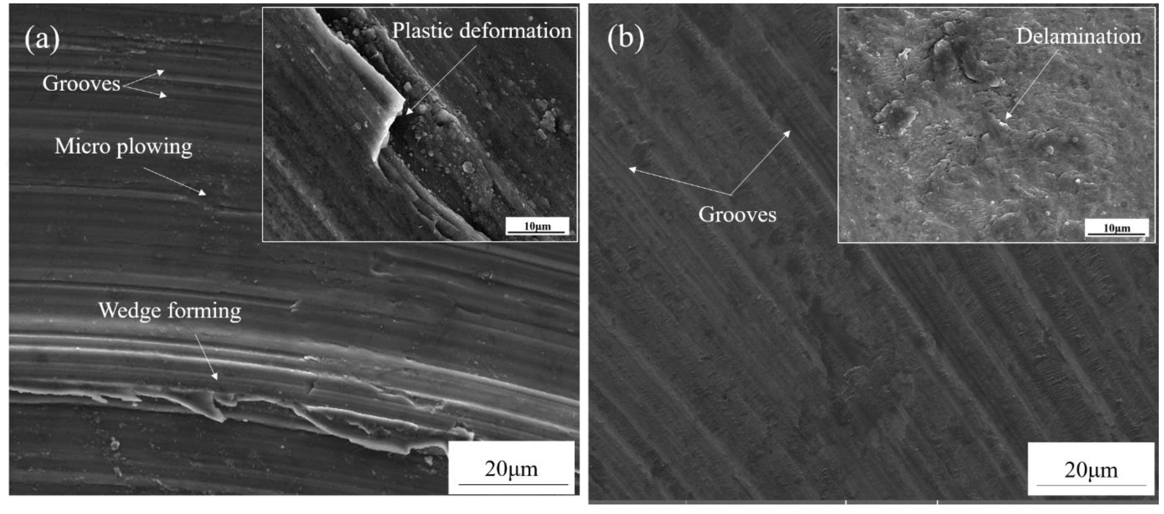
Under dry sliding conditions at room temperature, wear resistance of Ni60 was found to be much higher than that of the LA43M substrate, which was validated by wear weight loss and worn surface morphologies. The wear weight loss of the substrate was found to be 6.5 times higher than that of the coated specimen.

Author Contributions

Conceptualization, O.A., L.L.-Y. and L.C.-X.; validation, O.A., L.L.-Y. and L.C.-X.; investigation, O.A., L.L.-Y., M.Y. and L.C.-X.; resources, L.C.-X. and L.C.-J.; writing—original draft preparation, O.A. and L.C.-X.; writing—review and editing, L.L.-Y., M.Y., L.C.-X. and L.C.-J.; supervision, L.C.-X. and L.C.-J.; project administration, L.C.-X. and L.C.-J.; funding acquisition, L.C.-X. and L.C.-J. All authors have read and agreed to the published version of the manuscript.

Funding

This work was financially supported by the National Key R&D Program of China (No.2018YFB2002000), National Natural Science Foundation of China (No.51761145108), and Key Technological Innovations Project of Shandong Province (2019JZZY010802).

Acknowledgments

The authors wish to express their gratitude to Jinxi Wang and Haroon Rashid for their fruitful co-operation.

Conflicts of Interest

The authors declare no conflict of interest.

References

  1. Xu, D.K.; Wang, B.J.; Li, C.Q.; Zu, T.T.; Han, E.H. Effect of icosahedral phase on the thermal stability and ageing response of a duplex structured Mg-Li alloy. Mater. Des. 2015, 69, 124–129. [Google Scholar] [CrossRef]
  2. Xu, Y.; Li, K.; Yao, Z.; Jiang, Z.; Zhang, M. Micro-arc oxidation coatings on Mg-Li alloys. Rare Metals 2009, 28, 160–163. [Google Scholar] [CrossRef]
  3. Zhu, T.; Cui, C.; Zhang, T.; Wu, R.; Betsofen, S.; Leng, Z.; Zhang, J.; Zhang, M. Influence of the combined addition of Y and Nd on the microstructure and mechanical properties of Mg-Li alloy. Mater. Des. 2014, 57, 245–249. [Google Scholar] [CrossRef]
  4. Wang, N.; Wang, R.; Feng, Y.; Xiong, W.; Zhang, J.; Deng, M. Discharge and corrosion behaviour of Mg-Li-Al-Ce-Y-Zn alloy as the anode for Mg-air battery. Corros. Sci. 2016, 112, 13–24. [Google Scholar] [CrossRef]
  5. Zhou, W.R.; Zheng, Y.F.; Leeflang, M.A.; Zhou, J. Mechanical property, biocorrosion and in vitro biocompatibility evaluations of Mg–Li–(Al)–(RE) alloys for future cardiovascular stent application. Acta Biomater. 2013, 9, 8488–8498. [Google Scholar] [CrossRef]
  6. Hoche, H.; Schmidt, J.; Groß, S.; Troßmann, T.; Berger, C. PVD coating and substrate pretreatment concepts for corrosion and wear protection of magnesium alloys. Surf. Coat. Technol. 2011, 205, S145–S150. [Google Scholar] [CrossRef]
  7. Mao, Y.; Li, Z.; Feng, K.; Guo, X.; Zhou, Z.; Wu, Y. Corrosion behavior of carbon film coated magnesium alloy with electroless plating nickel interlayer. J. Mater. Process. Technol. 2015, 219, 42–47. [Google Scholar] [CrossRef]
  8. Kuo, Y.-L.; Chang, K.-H. Atmospheric pressure plasma enhanced chemical vapor deposition of SiOx films for improved corrosion resistant properties of AZ31 magnesium alloys. Surf. Coat. Technol. 2015, 283, 194–200. [Google Scholar] [CrossRef]
  9. Yin, T.; Wu, R.; Leng, Z.; Du, G.; Guo, X.; Zhang, M.; Zhang, J. The process of electroplating with Cu on the surface of Mg–Li alloy. Surf. Coat.Technol. 2013, 225, 119–125. [Google Scholar] [CrossRef]
  10. Yan, D.; Yu, G.; Hu, B.; Zhang, J.; Song, Z.; Zhang, X. An innovative procedure of electroless nickel plating in fluoride-free bath used for AZ91D magnesium alloy. J. Alloys Compd. 2015, 653, 271–278. [Google Scholar] [CrossRef]
  11. Wang, H.; Yu, B.; Wang, W.; Ren, G.; Liang, W.; Zhang, J. Improved corrosion resistance of AZ91D magnesium alloy by a zinc–yttrium coating. J. Alloys Compd. 2014, 582, 457–460. [Google Scholar] [CrossRef]
  12. Peat, T.; Galloway, A.M.; Toumpis, A.I.; Harvey, D. Evaluation of the synergistic erosion-corrosion behaviour of HVOF thermal spray coatings. Surf. Coat. Technol. 2016, 299, 37–48. [Google Scholar] [CrossRef] [Green Version]
  13. Taltavull, C.; Lopez, A.J.; Torres, B.; Atrens, A.; Rams, J. Optimisation of the high velocity oxygen fuel (HVOF) parameters to produce effective corrosion control coatings on AZ91 magnesium alloy. Mater. Corros. 2015, 66, 423–433. [Google Scholar] [CrossRef]
  14. Torres, B.; Taltavull, C.; López, A.J.; Campo, M.; Rams, J. Al/SiCp and Al11Si/SiCp coatings on AZ91 magnesium alloy by HVOF. Surf. Coat. Technol. 2015, 261, 130–140. [Google Scholar] [CrossRef]
  15. Tao, Y.; Xiong, T.; Sun, C.; Kong, L.; Cui, X.; Li, T.; Song, G.-L. Microstructure and corrosion performance of a cold sprayed aluminium coating on AZ91D magnesium alloy. Corros. Sci. 2010, 52, 3191–3197. [Google Scholar] [CrossRef]
  16. Chen, E.; Zhang, K.; Zou, J. Laser cladding of a Mg based Mg–Gd–Y–Zr alloy with Al–Si powders. Appl. Surf. Sci. 2016, 367, 11–18. [Google Scholar] [CrossRef]
  17. Huang, K.; Xie, C.; Lin, X.; Yue, T.M. Laser cladding of Zr-based coating on AZ91D magnesium alloy for improvement of wear and corrosion resistance. Bull. Mater. Sci. 2013, 36, 99–105. [Google Scholar] [CrossRef] [Green Version]
  18. Khanna, A.S.; Kumari, S.; Kanungo, S.; Gasser, A. Hard coatings based on thermal spray and laser cladding. Int. J. Refract. Met. Hard Mater. 2009, 27, 485–491. [Google Scholar] [CrossRef]
  19. Tan, C.; Zhu, H.; Kuang, T.; Shi, J.; Liu, H.; Liu, Z. Laser cladding Al-based amorphous-nanocrystalline composite coatings on AZ80 magnesium alloy under water cooling condition. J. Alloys Compd. 2017, 690, 108–115. [Google Scholar] [CrossRef]
  20. Weng, F.; Yu, H.; Chen, C.; Liu, J.; Zhao, L.; Dai, J.; Zhao, Z. Effect of process parameters on the microstructure evolution and wear property of the laser cladding coatings on Ti-6Al-4V alloy. J. Alloys Compd. 2017, 692, 989–996. [Google Scholar] [CrossRef]
  21. Zarezadeh Mehrizi, M.; Shamanian, M.; Saidi, A.; Shoja-Razazvi, R.; Beigi, R. Evaluation of oxidation behavior of laser clad CoWSi–WSi2 coating on pure Ni substrate at different temperatures. Ceram. Int. 2015, 41, 9715–9721. [Google Scholar] [CrossRef]
  22. Schopphoven, T.; Gasser, A.; Wissenbach, K.; Poprawe, R. Investigations on ultra-high-speed laser material deposition as alternative for hard chrome plating and thermal spraying. J. Laser Appl. 2016, 28, 022501. [Google Scholar] [CrossRef]
  23. Lou, L.; Zhang, Y.; Li, C.-X.; Li, C.-J.; Tian, H.; Tantai, F. Microstructure and surface morphology evolution of FeCr alloy thin coatingdeposited by ultra-high speed laser cladding with low laser power. J. Yanshan Univ. 2020, 44, 116–124. [Google Scholar]
  24. Li, L.; Shen, F.; Zhou, Y.; Tao, W. Comparative study of stainless steel AISI 431 coatings prepared by extreme-high-speed and conventional laser cladding. J. Laser Appl. 2019, 31. [Google Scholar] [CrossRef]
  25. Lu, Y.; Lu, G.; Liu, F.; Chen, Z.; Tang, K. Phase-field study on the pre-precipitated phase of ordered intermetallic compounds in binary and ternary Ni–Al base alloys. J. Alloys Compd. 2015, 637, 149–154. [Google Scholar] [CrossRef]
  26. Liu, K.; Li, Y.; Wang, J. In-situ reactive fabrication and effect of phosphorus on microstructure evolution of Ni/Ni–Al intermetallic composite coating by laser cladding. Mater. Des. 2016, 105, 171–178. [Google Scholar] [CrossRef]
  27. Weng, Z.; Wang, A.; Wu, X.; Wang, Y.; Yang, Z. Wear resistance of diode laser-clad Ni/WC composite coatings at different temperatures. Surf. Coat. Technol. 2016, 304, 283–292. [Google Scholar] [CrossRef]
  28. Luo, F.; Cockburn, A.; Sparkes, M.; Lupoi, R.; Chen, Z.-j.; O’Neill, W.; Yao, J.-h.; Liu, R. Performance characterization of Ni60-WC coating on steel processed with supersonic laser deposition. Def. Technol. 2015, 11, 35–47. [Google Scholar] [CrossRef] [Green Version]
  29. Wan, M.Q.; Shi, J.; Lei, L.; Cui, Z.Y.; Wang, H.L.; Wang, X. A Comparative Study of the Microstructure, Mechanical Properties and Corrosion Resistance of Ni- or Fe- Based Composite Coatings by Laser Cladding. J. Mater. Eng. Perform. 2018, 27, 2844–2854. [Google Scholar] [CrossRef]
  30. Yao, J.; Yang, L.; Li, B.; Li, Z. Characteristics and performance of hard Ni60 alloy coating produced with supersonic laser deposition technique. Mater. Des. 2015, 83, 26–35. [Google Scholar] [CrossRef]
  31. Wang, C.; Gao, Y.; Zeng, Z.; Fu, Y. Effect of rare-earth on friction and wear properties of laser cladding Ni-based coatings on 6063Al. J. Alloys Compd. 2017, 727, 278–285. [Google Scholar] [CrossRef]
  32. Liu, X.-B.; Liu, H.-Q.; Meng, X.-J.; Sun, C.-F.; Wang, M.-D.; Qi, L.-H.; Shi, G.-L.; Wu, S.-H. Effects of aging treatment on microstructure and tribological properties of nickel-based high-temperature self-lubrication wear resistant composite coatings by laser cladding. Mater. Chem. Phys. 2014, 143, 616–621. [Google Scholar] [CrossRef]
  33. Riquelme, A.; Rodrigo, P.; Escalera-Rodríguez, M.D.; Rams, J. Analysis and optimization of process parameters in Al–SiCp laser cladding. Opt. Lasers Eng. 2016, 78, 165–173. [Google Scholar] [CrossRef]
  34. Jun, Y.; Sun, G.P.; Wang, H.-Y.; Jia, S.Q.; Jia, S.S. Laser (Nd:YAG) cladding of AZ91D magnesium alloys with Al+Si+Al2O3. J. Alloys Compd. 2006, 407, 201–207. [Google Scholar] [CrossRef]
  35. Wang, A.H.; Yue, T.M. YAG laser cladding of an Al-Si alloy onto an Mg/SiC composite for the improvement of corrosion resistance. Compos. Sci. Technol. 2001, 61, 1549–1554. [Google Scholar] [CrossRef]
  36. Yue, T.M.; Xie, H.; Lin, X.; Yang, H.O.; Meng, G.H. Solidification behaviour in laser cladding of AlCoCrCuFeNi high-entropy alloy on magnesium substrates. J. Alloys Compd. 2014, 587, 588–593. [Google Scholar] [CrossRef]
  37. Hemmati, I.; Ocelík, V.; De Hosson, J.T.M. Dilution effects in laser cladding of Ni–Cr–B–Si–C hardfacing alloys. Mater. Lett. 2012, 84, 69–72. [Google Scholar] [CrossRef]
  38. Gao, Y.; Xiong, D.; Wang, C.; Chen, Y. Influences of laser powers on microstructure and properties of the coatings on the AZ91HP magnesium alloy. Acta Metall. Sin. Engl. Lett. 2009, 22, 167–173. [Google Scholar] [CrossRef] [Green Version]
  39. Zhu, R.; Li, Z.; Li, X.; Sun, Q. Microstructure and properties of the low-power-laser clad coatings on magnesium alloy with different amount of rare earth addition. Appl. Surf. Sci. 2015, 353, 405–413. [Google Scholar] [CrossRef]
  40. Zhou, J.; Xu, J.; Huang, S.; Hu, Z.; Meng, X.; Feng, X. Effect of laser surface melting with alternating magnetic field on wear and corrosion resistance of magnesium alloy. Surf. Coat. Technol. 2017, 309, 212–219. [Google Scholar] [CrossRef]
  41. Wang, J.; Jia, Q.; Yuan, X.; Wang, S. Experimental study on friction and wear behaviour of amorphous carbon coatings for mechanical seals in cryogenic environment. Appl. Surf. Sci. 2012, 258, 9531–9535. [Google Scholar] [CrossRef]
  42. Zhang, P.; Yan, H.; Yao, C.; Li, Z.; Yu, Z.; Xu, P. Synthesis of Fe–Ni–B–Si–Nb amorphous and crystalline composite coatings by laser cladding and remelting. Surf. Coat. Technol. 2011, 206, 1229–1236. [Google Scholar] [CrossRef]
Figure 1. Ni60 powder: (a) scanning electron microscopy (SEM) morphology; (b) size distribution.
Coatings 10 00638 g001
Figure 2. (a) Arrangements of the laser cladding system and (b) sketch of laser cladding process.
Coatings 10 00638 g002
Figure 3. Backscattered images showing coating microstructure at several distances from surface of the substrate: (a) cross section morphology of Ni60 coating specimen; (b) magnified morphology of area ‘B1’; (c) magnified morphology of area ‘B2’; (d) magnified morphology of area ‘B3’; (e) solidified Ni60 coating which exhibits typical dendritic structure: inset refers to more details of the interdendritic region.
Coatings 10 00638 g003
Figure 4. X-ray diffraction (XRD) pattern of Ni60 coating and substrate.
Coatings 10 00638 g004
Figure 5. Microhardness distribution curve of laser-clad Ni60 coating.
Coatings 10 00638 g005
Figure 6. The friction coefficient curves of Ni60 coating and substrate.
Coatings 10 00638 g006
Figure 7. 3D and 2D cross-sectional profile of wear scar of (a) substrate and (b) Ni60 coating.
Coatings 10 00638 g007
Figure 8. The wear scar width (a) and depth (b) of substrate and Ni60 coating.
Coatings 10 00638 g008
Figure 9. SEM morphologies of worn surfaces for (a) substrate and (b) Ni60 coating.
Coatings 10 00638 g009
Table 1. Chemical composition of the LA43M substrate and Ni60 alloy powder (wt.%).
ElementMgAlLiZnSiFeCuCrNiBC
Ni-60----4.514.5-18.5Bal.3.00.1
LA43MBal.2.5–3.53.5–4.52.5–3.50.50.050.05
Table 2. Optimal processing parameters for Ni60 coating.
Feeding Rate
(g/min)
Linear Velocity
(mm/s)
Laser Spot Diameter
(mm)
Laser Power
(kW)
241722.62.5
Table 3. Elemental concentrations (wt.%) of the selected areas in the laser cladding Ni60 coating from energy dispersive spectrometer (EDS) analysis.
ElementsCSiCrFeNi
A1
A2
6.43
2.74
4.08
1.44
25.69
14.56
12.31
18.75
51.49
62.51
Table 4. Wear volume and specific wear rate of substrate and Ni60 coating.
SpecimenVolume Loss (mm3)Specific Wear Rate (mm3 N−1 m−1)
LA43M
Ni60 Coating
1.196
0.015
6.35 × 10⁻²
8.35 × 10⁻⁴

