Article

Morphology, Hardness and Wear Properties of Plasma Cladding NiCrCu Coating on M2 High-Speed Steel

1
College of Materials and Metallurgy, Guizhou University, Guiyang 550025, China
2
Key Laboratory for Mechanical Behavior and Microstructure of Materials, Guizhou University, Guiyang 550025, China
*
Author to whom correspondence should be addressed.
Coatings 2020, 10(7), 641; https://doi.org/10.3390/coatings10070641
Submission received: 12 June 2020 / Revised: 27 June 2020 / Accepted: 29 June 2020 / Published: 30 June 2020

Abstract

:
To improve the cutting performance, the red hardness and wear resistance of M2 high-speed steel, as well as expand the application field, in this work, a coating was fabricated via plasma cladding on M2 high-speed steel using Ni, Cr and Cu alloy elements as precursor materials. The distribution and composition of alloying elements, microhardness and wear resistance of the coating were studied. The results show that the NiCrCu cladding layer contains many types of carbides. The secondary hardening caused by the dispersion of carbides can significantly improve the hardness, red hardness and wear resistance of material. The hardness of cladding layer is above 950 HV, after holding at 600 °C for 4 h, the hardness is above 932 HV. The alloy elements are evenly distributed, but, due to the rapid solidification after the cladding, there are composition fluctuations in the longitudinal direction. The wear resistance of the cladding layer is excellent; the wear rate is reduced from 1.75 to 1.44 × 10⁻⁶ mm3 N−1 m−1 or less; and the wear mechanism is a combination of abrasive wear and adhesive wear.

1. Introduction

High-speed steels have excellent hardness and wear resistance even at elevated temperatures, and are widely used in cutting tools and other applications [1,2,3]. The excellent performance of high-speed steels is due to their characteristic microstructure, especially the morphology and distribution of carbides and the well-defined balance of alloying elements [4,5,6]. The resistance of cutting tool materials to wear is the primary concern in their applicability in cutting operations [7]. The mechanical behavior of high-speed steels can be enhanced via surface coatings and their performance can be improved through modification, alloying, heat treatment and forging [8,9,10]. Plasma cladding involves the use of high-power density beam to a coat layer or layers of the surface parts for the improvement of the surface properties [11]. Given the compact coating, high binding strength, wide availability of materials, high efficiency and low cost of plasma cladding, it has been developed rapidly in surface engineering [12,13,14,15] and widely used in strengthening and repairing parts.
Recently, considerable efforts have been exerted to study surface coatings. Kaiming et al. [16] fabricated Ni-based composite coating on the surface of 42CrMo steel. The results indicate that the wear resistance of Ni45 + 10%Mo composite coating reaches 1.734 and 2.367 times those of the Ni45 coating and the 42CrMo steel, respectively. Sharifitabar et al. [17] fabricated Fe–TiC–Al2O3 coatings on the surface of 1045 steel via gas tungsten arc cladding. The results indicate that the incomplete dissolution of some TiC forms TiC–Al2O3 colonies in the structure of coatings, which increases the hardness of 1045 steel from 350 to 830 HV and improves wear resistance. Ma et al. [18] fabricated WC-reinforced and Ni-based composite coatings on the surface of Q550 steel via wide-band laser cladding. The refined ceramic–eutectic structure enhances the wear properties of the composite coating significantly, and the maximum wear loss of the substrate is 6.8 times that of the cladding layer. Ma et al. [19] fabricated WC-reinforced and Co–Fe–Cr-based composite coatings on the surface of Q550 steel via laser cladding. After adding 50 wt.% WC coating, the hardness of Q550 steel is increased from 289 to 668 HV, which is 2.3 times higher. Ni-based alloy powders are cheap and exhibit good wettability, wear resistance and corrosion resistance at high temperatures. These powders have been widely used in surface repair, including cladding technology [20,21,22]. Cr can significantly improve the hardness, wear resistance and oxidation resistance of the material. Cu has excellent electrical and thermal conductivity, strength, ductility and fatigue resistance [23], which is beneficial to improve the mechanical properties of the cladding layer. To improve the red hardness, wear resistance, cutting performance and expand the application field of M2 high-speed steel, we studied the effect of cladding NiCrCu coating over M2 high-speed steel.
In this study, a layer of NiCrCu alloy powder was precoated on the surface of M2 high-speed steel. Thereafter, plasma cladding technology was used to prepare the cladding layer, and the hardness and red hardness, wear resistance, phase composition and element distribution of the cladding layer before and after tempering were investigated. The results of the study may serve as an important reference for the expansion and development of new types of coatings applied on M2 high-speed steel.

2. Experimental

2.1. Materials and Fabrication of Plasma Cladding Layer

The substrate was M2 high-speed steel with dimensions of 150 × 18 × 10 mm3. Before cladding, the substrate was polished with SiC abrasive paper (800 mesh) and cleaned with acetone. The chemical constituents of M2 high-speed steel are shown in Table 1. The raw materials of coating used were Ni (>99.8%, <100 μm), Cr (>99.9%, <100 μm) and Cu (>99.9%, <100 μm) with a ratio of 6:3:1. A small amount of ethanol-based solution containing 3 wt.% polyvinyl acetate as agglomerant was added. The raw materials were thoroughly mixed using a sodium silicate blender for 1 h to produce a homogenous mixture. This coating solution was preplaced onto the surface of the substrate as a precursor with thickness and width of 0.5 and 18 mm, respectively, and dried 12 h at room temperature.
The plasma cladding diagram is shown in Figure 1. The parameters of the plasma cladding were as follows. The output power of plasma was 4.4 kW, the cladding speed was 800 mm/min, Ar gas was used as shielding and working gas, the gas flow was 1 L/min, the torch was 4 mm and spot diameter was 2 mm. After cladding was completed, the cladding layer was cut with a wire to form 5 × 2 × 3 mm3 samples (Samples A and B shown in Figure 1; their cross sections were the same) for subsequent heat treatment, as shown in Figure 2. Samples A and B were tempered thrice at the same temperature to eliminate the stress generated during plasma cladding and cause solid solution strengthening of the M2 high-speed, as shown in Figure 2a. Then, the tempered Sample B was kept at 600 °C for 4 h, as shown in Figure 2b, and cooled to room temperature. The hardness of Sample B was used as an indicator of the red hardness of steel. The hardness of Sample A was used as the tempering hardness.

2.2. Hardness and Wear Resistance Testing

The microhardness profile along the cross-section of the plasma cladding samples was measured using a microhardness tester (HVS-1000, FUTURE-TECH CORP, Kanagawa, Japan) under the load of 100 g, dwell time was 10 s and the average distance between two points was 0.05 mm. The microhardness value of each sample was the average value of three parallel measurements on the cross-section.
Figure 3 shows the schematic diagram of the wear test process, wear sample size was 18 × 10 × 10 mm3 (shown in Figure 1). The dry sliding wear tests were performed under room temperature conditions with a ball-on-disk model by using a micro-tribometer (HSR-2M, Changzhou Ruipin Precision Instrument Co., Ltd., Changzhou, China) with a load of 50 N for 2 h, a sliding distance of 5 mm and a sliding velocity of 500 rpm. An Al2O3 ball with a diameter of 4.0 mm was used as a counter body. The wear volume was determined using the depth and width of wear scars measured using a 3D profiler (OLS 5000, Olympus Corporation, Tokyo, Japan). The wear volume was calculated using Equation (1) [24]:
Δ V = [ r 2 × arccos ( r d r ) W × r d 2 ] × L
where W, d and L are the width, depth, and length of the wear scar, respectively, and r is the outer radius of the wear ball. The wear rate was calculated using Equation (2):
ω = Δ V D × P
where ω is the wear rate, D is the wear distance and P is the load.

2.3. X-ray Diffraction (XRD) and Scanning Electron Microscopy (SEM)

XRD patterns were obtained using an X-ray diffractometer (D/MAX2500PC, Rigaku Corporation, Tokyo, Japan) with Cu Kα radiation at a scanning rate of 4°/min and scanning angles ranged from 30° to 90°; before the coating was analyzed by XRD, its upper part was polished to produce a flat surface. The microstructure of the coating was analyzed using field emission scanning electron microscopy (SUPRA40, Carl Zeiss AG) with energy dispersive spectroscopy (EDS), before coating was analyzed by SEM (SUPRA40, Carl Zeiss AG, Oberkochen, Germany) the cross section of coating needed to be polished and etched with 4% nitric alcohol.

3. Results and Discussion

3.1. Phase Component of Coatings

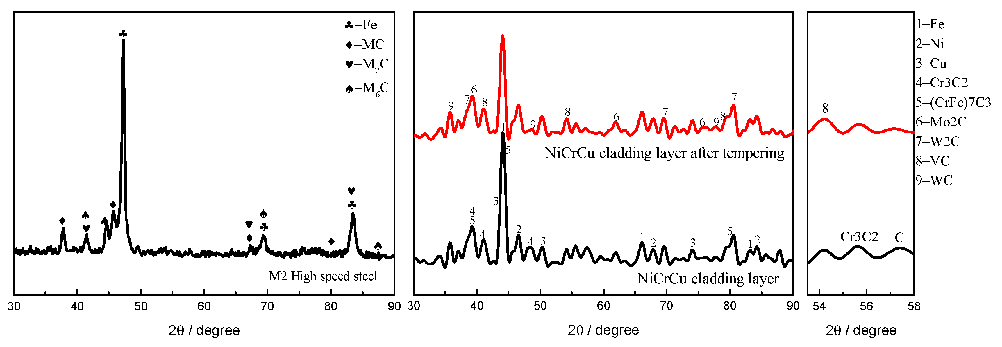
Figure 4 shows the XRD patterns of M2 high-speed steel after quenching and cladding layer. The quenched M2 high-speed steel mainly contains three types of carbides, and, after cladding NiCrCu coating, the precipitation of carbides increases; they are mainly MC and M2C carbides of W2C, WC, Mo2C and VC [25]. Due to the addition of Cr element in coating, the Cr3C2 ceramic phase is generated during cladding, and the dissolution of Cr3C2 particles in the molten pool would lead to the enrichment of carbon and chromium in the matrix, resulting in the formation of M7C3 (M = Fe and Cr) [26]. The peaks with reduced strength (in range of 54°–60° 2θ) were identified as Cr3C2 and C. Mainly after tempering, other types of strong carbides were precipitated in the substrate, resulting in the reduction of Cr3C2 and C peaks. The temperatures at which Mn, Cr, Mo and V can significantly diffuse in ferrite are 350, 400–450, 500 and 500–550 °C, respectively, and this difference in diffusion temperature affects the type and composition of the carbide. Self-tempering at the end of cladding would cause the precipitation of carbides; thus, after the subsequent tempering, no new phases were formed. During plasma cladding, Ar gas insulated Cu from oxygen; thus, no copper compounds were formed and Cu element is present in the form of unbound Cu on the in cladding layer [27].

3.2. Microstructure

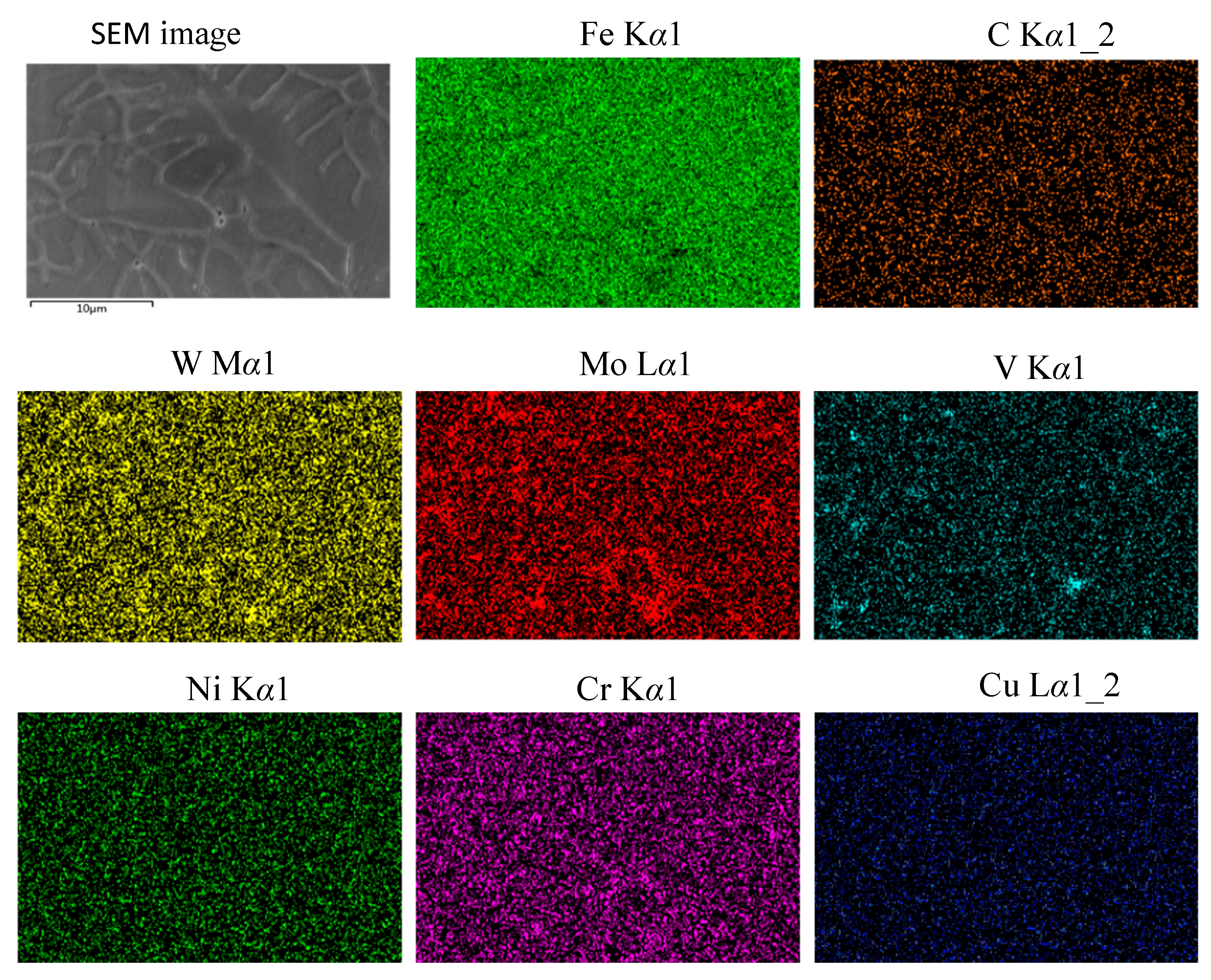
Figure 5 shows the SEM of longitudinal-sectional microstructure of cladding layer. Figure 5b,c represents the microstructure of the top and middle of the coating, respectively. The surface structure of the cladding layer is equiaxed crystal, and the internal structure mainly is dendritic crystal. The alloy solidification after cladding meets the structural super cooling criterion [28,29], the temperature gradient G at the solid–liquid interface and the solidification rate R are the main factors which determine the morphology of coating crystal growth. At the end of cladding, the temperature gradient of the solid–liquid interface between the substrate and molten pool is small, and the solidification rate is relatively large. Therefore, the G/R value is small and forms dendritic crystal, as shown in Figure 5c. As the solid–liquid interface moves toward the surface, the molten pool gradually moves away from the substrate, the heat dissipation perpendicular to the substrate direction is further weakened, the G/R value continues to decrease and more heat is transferred to the left and right sides of the molten pool, resulting in the dendritic crystal grow in different directions and transforms to equiaxed one [30], as shown in Figure 5b. The morphology of dendritic and equiaxed grain and its element distribution are shown in Figure 6 and Figure 7, respectively. The high temperature plasma arc makes the carbide and alloy powders fully melt into the matrix. After the cladding, the carbides dissolved in the matrix are dispersed and evenly distributed in the cladding layer. Therefore, the elements in the coating are evenly distributed without obvious segregation.
Figure 8 shows the microstructure of top region of tempered coating. The detailed morphology is presented in Figure 8b, and the EDS point analysis corresponding to Figure 8b is shown in Table 2. After the coating was tempered, it is mainly lamellar tempered martensite structure, and that white areas are present around the grain boundary. The point scan results show that Points B and C in the grain boundary contain more alloying elements, while Point A is rich in Fe and Ni element, mainly the Fe and Ni substrate.
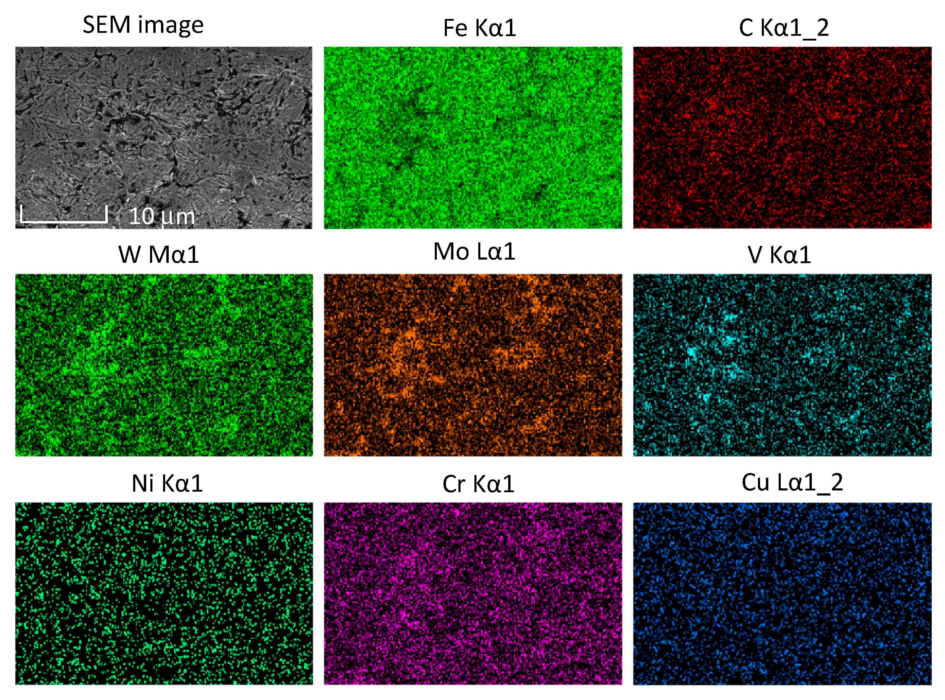
Figure 9 shows the EDS mapping analysis results of the plasma cladding coating. After tempering, alloy elements in the cladding layer are slightly segregated. The Fe element content in the grain boundary area is relatively low, while the W, Mo and V element contents are relatively high. The Cu element is well incorporated into the coating [31], and Ni and Cr elements are evenly distributed in the coating. Due to the extremely high temperature of the plasma arc during cladding, the alloying elements in the cladding layer solid-dissolve into the substrate, forms fine and dispersed carbide particles and then precipitates, causing secondary hardening. This results in an even distribution of alloying elements in the cladding layer, with excellent hardness and red hardness.
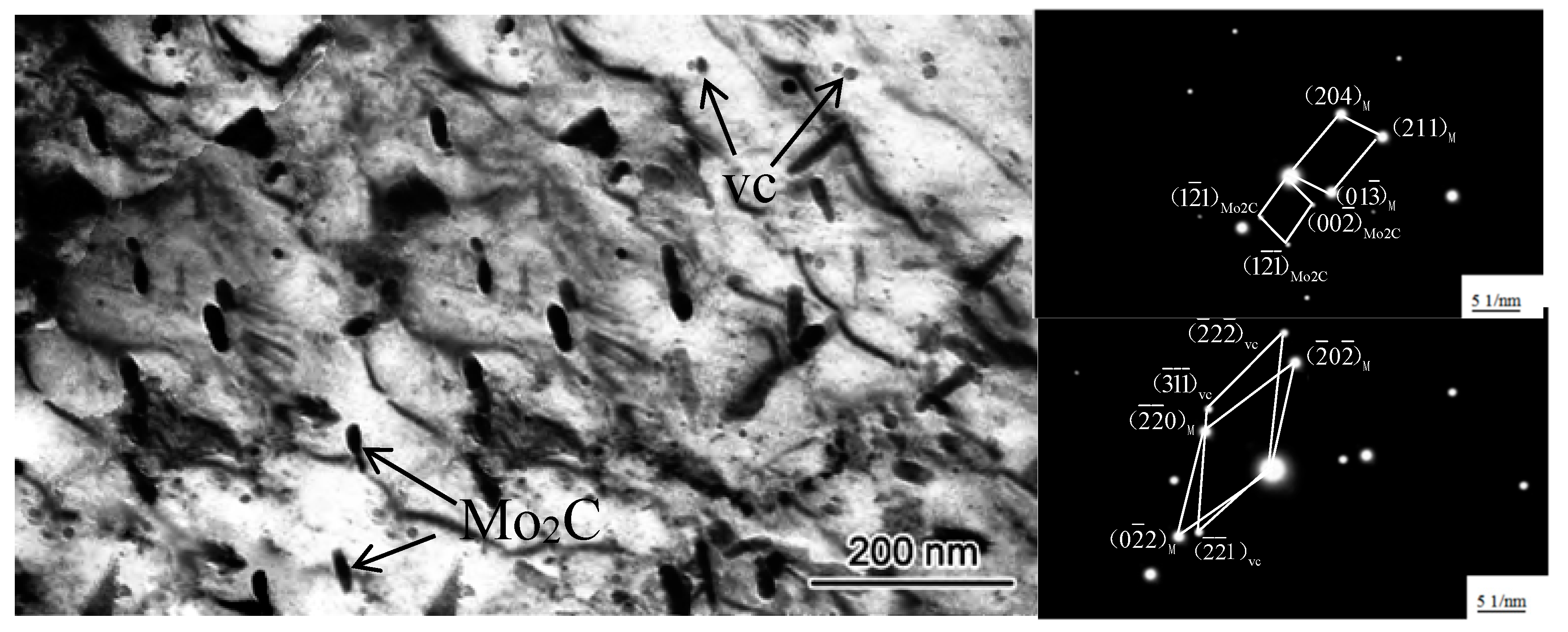
A large amount of secondary carbides is dispersed and precipitated in the cladding layer. The shape of the carbides is granular and striped. As shown in Figure 10, combined with the results of selective diffraction, the granular particles are Mo2C carbide and the size is about 40 nm, which is coplanar with the martensite. The striped particles are VC carbide and the diameter is about 8 nm. Carbides are precipitated from austenite after cladding, and the austenite is cooled and transformed into martensite.
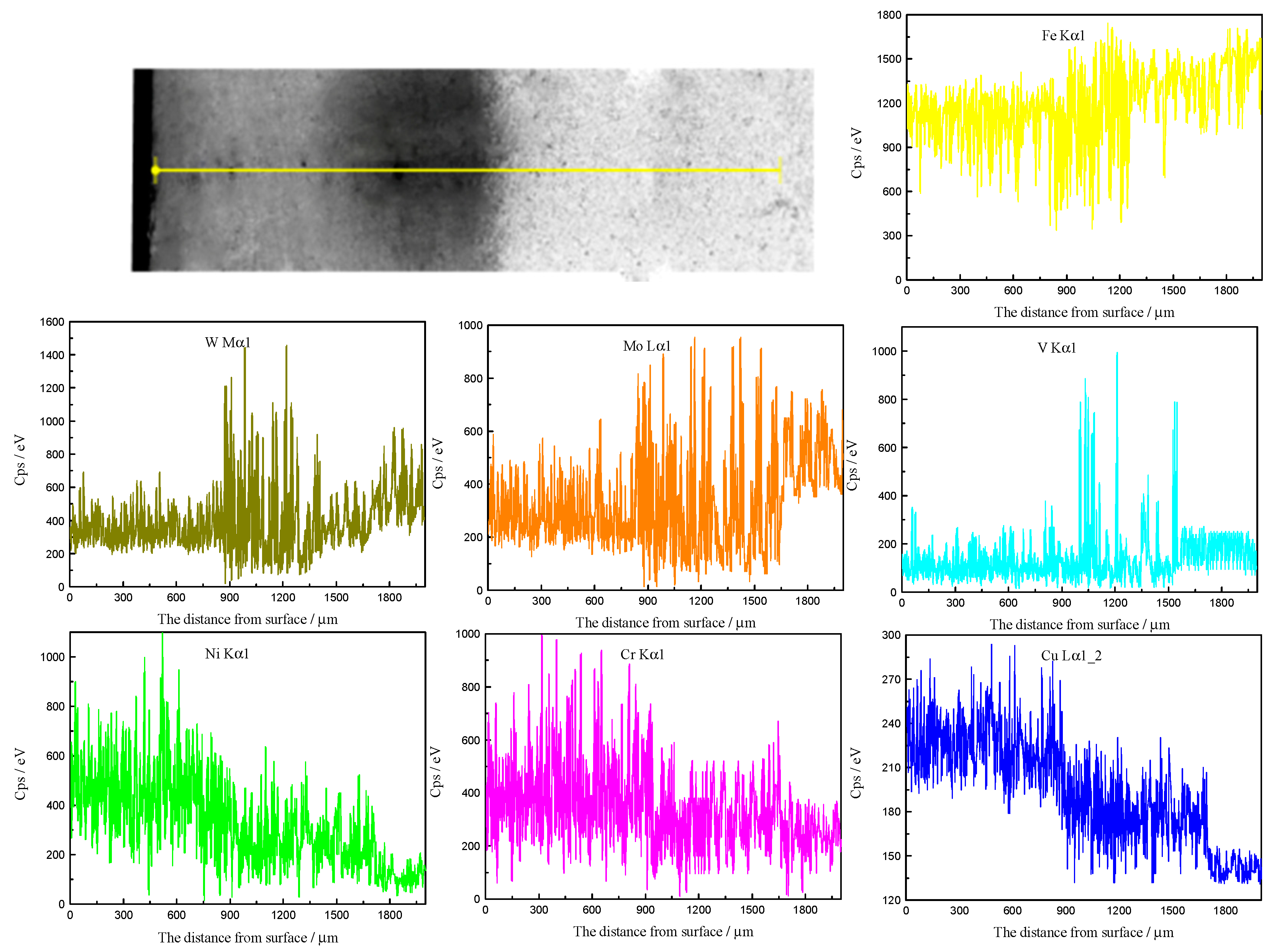
Figure 11 shows the element distribution determined through the EDS line scan analysis. The cladding layer and the dilution layer have achieved metallurgical bonding through plasma cladding. Because the cladding layer element has excellent thermal conductivity, cracks and pores are not displayed. The thickness of the coating is about 900 μm, cladding layer is 1700 μm and substrate is 1700–2000 μm. The Fe element in coating is slightly reduced because the coating contains more NiCrCu elements. Compared with the dilution layer, the content of V, Mo and W elements in the coating are significantly reduced. About 870 μm from the surface, the content of W and Mo elements increases significantly, while, at the dilution layer about 990 μm from the surface, the content of V element increases significantly. The content of alloying elements of Ni, Cr and Cu gradually decreases with distance. Unlike the uniform distribution of alloy elements in mapping scan, after the cladding, alloy elements, especially carbide-forming elements W, Mo, V and C, are unevenly distributed in the longitudinal direction of the cladding layer.
The plasma arc temperature reached 20K °C, and the coating and substrate melt and mix to form cladding layer. During this process, some alloy elements of the coating and dilution layer diffuse with each other. In addition, Pan et al. [32] found that the molten pool surface outward convection is mainly induced by the drag force of the cathode jet and Marangoni force, whereas the inward convection is caused by the electromagnetic force. Under the action of the drag force of the cathode jet and Marangoni force, the alloy elements diffuse into the entire coating. Under the action of the electromagnetic force, the alloy elements evenly distribute, but, in the longitudinal direction of the cladding layer, the alloy elements distribute unevenly; because the cooling rate of cladding layer is too fast, during solidification, the alloying elements in the dilution layer have no time to diffuse into the coating and concentrate at the boundary between the coating and dilution layer. The process is shown in Figure 12.

3.3. Microhardness

Figure 13 presents the microhardness distribution of cladding layer along the depth direction. The cladding layer includes two parts: the coating and dilution layer. During cladding, the dilution layer was mainly affected by the heat transfer of coating, and its hardness curve shows a downward trend. The thickness of coating is about 0.9 mm and the thickness of cladding layer is about 1.67 mm. Figure 13a shows the hardness of cladding layer after tempering. Figure 13b shows the hardness of cladding layer after holding at 600 °C for 4 h. The average hardness values of M2 high-speed steel oil-quenched at 1200 °C and tempered at 600 °C is about 840 HV. After cladding NiCrCu coating, the surface hardness is increased to above 950 HV. After holding at 600 °C for 4 h, M2 high speed steel is about 820 HV and the surface hardness of NiCrCu coating is above 932 HV; the coating has high hardness and excellent red hardness performance. There are more types of carbides produced by plasma cladding and the precipitated carbides can keep the cladding layer with higher hardness and red hardness [33,34,35]. Since the plasma arc temperature reaches 20k °C, all the carbides and alloy powders melt into the matrix during cladding, and its solid solubility is much higher than the solid solubility of M2 high-speed steel after quenching. M2 high-speed steel precipitates more carbide after quenching and the hardness is only 840 HV. After tempering, the solid solubility of martensite decreases, resulting in a decrease in the solid solution strengthening effect, but all the carbides formed by cladding are precipitated in the form of fine and dispersed. These large amounts of finely dispersed carbides evenly distributed in the cladding layer, a strong secondary hardening effect is formed, making the cladding layer hardness reach 950–1120 HV, while, when the tempering temperature increases, the carbides grow and the hardness of the cladding layer decreases.

3.4. Dry Sliding Wear Behavior

The data presented in Figure 14 show that the coefficient of friction curves of cladding layer. The friction coefficient of quenched and tempered M2 high-speed steel is 0.63. After cladding NiCrCu coating, the friction coefficient reduces and the wear resistance is improved. The fine structure of cladding layer can effectively reduce the microscopic cutting effect, resist the frictional tensile stress of material, suppress the presence and fall of the abrasive debris under the frictional tensile stress and improve the wear resistance of the material. After cladding, the retained austenite is transformed into martensite, which can effectively suppress the form of crack and crack propagation. Since there is no network carbide at the martensite grain boundary, it can effectively prevent the increase of the wear rate of the carbide falling off. At the same time, the energy required for the transformation of austenite to martensite comes from outside, thus the formation of high-strain martensite improves the resistance to wear of material. The secondary hardening effect caused by the dispersed carbides increases the hardness and wear resistance of the material, and the dilution layer provides a buffer for the coating and substrate, slowing the release of the internal stress of the cladding layer and preventing the coating from falling off due to the excessive internal stress.
The 3D profiles and images of the wear track are shown in Figure 15. Differences are observed in the width and length of the wear tracks. The volume wear rate was calculated using the data from the 3D profiles and applying Equations (1) and (2); the results are shown in Figure 16. Many grooves and adhesion marks are observed on the surface of M2 high-speed steel and cladding layer. The surface contains Al element, thus the wear mechanism is a combination of abrasive wear and adhesive wear. The wear cross-sectional area of M2 high-speed steel is 87660 μm2 and the wear rate is 1.75 × 10⁻⁶ mm3 N−1 m−1. After cladding NiCrCu coating, the wear cross-sectional area and surface wear rate reduce, which effectively improves the wear resistance of the material surface.

4. Conclusions

The following conclusions are drawn from the experimental results and analysis.
  • The NiCrCu cladding layer contains many types of carbides, has no obvious defects and combines well with M2 high-speed steel. The alloy elements of the cladding layer are evenly distributed, but there are differences in the longitudinal direction; because the cladding layer cooling rate is fast, during solidification, the alloying elements in the dilution layer has no time to diffuse into the coating and concentrate at the boundary between the coating and dilution layer.
  • The precipitated carbide after cladding causes secondary hardening of the cladding layer, which effectively improves the hardness and red hardness of M2 high-speed steel. The hardness of quenched M2 high-speed steel is 840 HV. After cladding, the hardness increases to above 950 HV. After holding at 600 °C for 4 h, the hardness increases from 820 to 932 HV. The cladding layer has excellent red hardness performance.
  • The NiCrCu cladding layer effectively improves the wear resistance of material. The fine structure and dispersed carbides increase the wear resistance of the material. The wear rate is reduced from 1.75 to 1.44 × 10⁻⁶ mm3 N−1 m−1 or less, and the wear mechanism is a combination of abrasive wear and adhesive wear.

Author Contributions

Data analysis, data interpretation and writing, S.Z.; resources and funding acquisition, M.L.; grammatical of the manuscript, M.W.; manuscript revision and review, C.H. All authors have read and agreed to the published version of the manuscript.

Funding

This research was funded by Guizhou Science and Technology Plan Project (Grant No. GY[2012]3044).

Conflicts of Interest

The authors declare no conflict of interest.

References

  1. Malik, H.I.; Mgaloblishvili, R.; Mills, B. Effect of TiN coating thickness on performance of HSS cutting tools when machining free cutting steels. J. Mater. Sci. Lett. 2000, 19, 1779–1781. [Google Scholar] [CrossRef]
  2. Pan, F.S.; Wang, W.Q.; Tang, A.T.; Wu, L.Z.; Liu, T.T.; Cheng, R.J. Phase transformation refinement of coarse primary carbides in M2 high speed steel. Prog. Nat. Sci. Mater. Int. 2011, 21, 180–186. [Google Scholar] [CrossRef] [Green Version]
  3. Ji, Y.L.; Zhang, W.; Chen, X.Y.; Li, J.G. Increasing solidification rate of M2 high speed steel ingot by fusible metal mold. Acta Metall. Sn. (Engl. Lett.) 2016, 29, 382–387. [Google Scholar] [CrossRef] [Green Version]
  4. Zhou, X.F.; Zhu, W.L.; Jiang, H.B.; Fang, F.; Tu, Y.Y.; Jiang, J.Q. A new approach for refining carbide dimensions in M42 super hard high speed steel. J. Iron Steel Res. Int. 2016, 23, 800–807. [Google Scholar] [CrossRef]
  5. Zhou, X.F.; Fang, F.; Li, F.; Jiang, J.Q. Morphology and microstructure of M2C carbide formed at different cooling rates in AISI M2 high speed steel. J. Mater. Sci. 2011, 46, 1196–1202. [Google Scholar] [CrossRef]
  6. Chaus, A.S.; Beznák, M.; Porubský, J.; Sojka, J. Effect of austenitising temperature on microstructural changes in high-speed steel of M2 type inoculated with addition of WC powder. Defect Diffus. Forum. 2013, 333, 27–32. [Google Scholar] [CrossRef]
  7. Darmawan, W.; Quesada, J.; Marchal, R. Characteristics of laser melted AISI-T1 high speed steel and its wear resistance. Surf. Eng. 2007, 23, 112–119. [Google Scholar] [CrossRef]
  8. Lu, B.; Cui, X.; Li, Y.; Cai, Z.; Liu, E.; Jin, G.; Hu, Y. Microstructure, bonding properties and the basis of pinning effect of in-situ NbC reinforced Co50 composite coating by plasma cladding. Surf. Coat. Technol. 2017, 319, 155–163. [Google Scholar] [CrossRef]
  9. Lu, L.; Hou, L.G.; Cui, H.; Huang, J.F.; Zhang, Y.A.; Zhang, J.S. Hot deformation behavior and processing map of spray formed M3:2 high speed steel. J. Iron Steel Res. Int. 2016, 23, 501–508. [Google Scholar] [CrossRef]
  10. Zhao, S.L.; Fan, J.F.; Zhang, J.Y.; Chou, K.C.; Le, H.R. High speed steel produced by spray forming. Adv. Manuf. 2016, 4, 115–122. [Google Scholar] [CrossRef]
  11. Jin, G.; Li, Y.; Cui, H.; Cui, X.; Cai, Z. Microstructure and tribological properties of in situ synthesized TiN reinforced Ni/Ti alloy clad layer prepared by plasma cladding technique. J. Mater. Eng. Perform. 2016, 25, 2412–2419. [Google Scholar] [CrossRef]
  12. Liu, Q.X.; Lu, D.P.; Lu, L.; Hu, Q.; Fu, Q.F.; Zhou, Z. Effect of mischmetal on as-cast microstructure and mechanical properties of M2 high speed steel. J. Iron Steel Res. Int. 2015, 22, 245–249. [Google Scholar] [CrossRef]
  13. Li, Y.; Cui, X.; Jin, G.; Cai, Z.; Tan, N.; Lu, B.; Gao, Z. Interfacial bonding properties between cobalt-based plasma cladding layer and substrate under tensile conditions. Mater. Des. 2017, 123, 54–63. [Google Scholar] [CrossRef]
  14. Cao, H.T.; Dong, X.P.; Pan, Z.; Wu, X.W.; Huang, Q.W.; Pei, Y.T. Surface alloying of high-vanadium high-speed steel on ductile iron using plasma transferred arc technique: Microstructure and wear properties. Mater. Des. 2016, 100, 223–234. [Google Scholar] [CrossRef]
  15. Zhang, D.; Liu, Y.; Yin, Y. Preparation of plasma cladding gradient wear-resistant layer and study on its impact fatigue properties. J. Therm. Spray Technol. 2016, 25, 535–545. [Google Scholar] [CrossRef]
  16. Kaiming, W.; Yulong, L.; Hanguang, F.; Yongping, L.; Zhenqing, S.; Pengfei, M. A study of laser cladding NiCrBSi/Mo composite coatings. Surf. Eng. 2016, 34, 267–275. [Google Scholar] [CrossRef]
  17. Sharifitabar, M.; Khaki, J.V.; Sabzevar, M.H. Microstructure and wear resistance of in-situ TiC-Al2O3 particles reinforced Fe-based coatings produced by gas tungsten arc cladding. Surf. Coat. Technol. 2016, 285, 47–56. [Google Scholar] [CrossRef]
  18. Ma, Q.; Li, Y.; Wang, J.; Liu, K. Microstructure evolution and growth control of ceramic particles in wide-band laser clad Ni60/WC composite coatings. Mater. Des. 2016, 92, 897–905. [Google Scholar] [CrossRef]
  19. Ma, Q.; Li, Y.; Wang, J. Surface modification of Q550 HSLA steel with Co–Fe–Cr composite coatings manufactured by fibre laser cladding. Surf. Eng. 2016, 32, 934–942. [Google Scholar] [CrossRef]
  20. Ghosh, D.; Mitra, S.K. Plasma sprayed Cr3C2–Ni–Cr coating for oxidation protection of 2.25Cr–1Mo steel. Surf. Eng. 2015, 31, 342–348. [Google Scholar] [CrossRef]
  21. Posmyk, A. Composite coating with ceramic matrix including nickel nanowires. Surf. Eng. 2013, 29, 171–176. [Google Scholar] [CrossRef]
  22. Amado, J.M.; Montero, J.; Tobar, M.J.; Yáñez, A. Laser cladding of Ni-WC layers with graded WC content. Phys. Procedia. 2014, 56, 269–275. [Google Scholar] [CrossRef] [Green Version]
  23. Stathokostopoulos, D.; Chaliampalias, D.; Pliatsikas, N.; Kassavetis, S.; Pavlidou, E.; Patsalas, P.; Logothetidis, S.; Chrissafis, K.; Vourlias, G. Ti and nitride surface modification of copper by pack cementation. Surf. Eng. 2018, 34, 243–250. [Google Scholar] [CrossRef]
  24. Zhang, X.J.; Cui, H.Z.; Wang, J.F.; Zhang, G.S.; Zhao, Y.Q.; Kang, S.U.N. Effects of TiB2+TiC content on microstructure and wear resistance of Ni55-based composite coatings produced by plasma cladding. Trans. Nonferrous Met. Soc. China 2019, 29, 132–142. [Google Scholar] [CrossRef]
  25. Wen, T.; Hu, X.; Song, Y.; Yan, D.; Rong, L. Effect of tempering temperature on carbide and mechanical properties in a Fe-Cr-Ni-Mo high-strength steel. Acta Metall. Sin. 2014, 50, 447–453. [Google Scholar] [CrossRef]
  26. Zhang, D.W.; Lei, T.C. The microstructure and erosive-corrosive wear performance of laser-clad Ni- Cr3C2 composite coating. Wear 2003, 255, 129–133. [Google Scholar] [CrossRef]
  27. Zhang, X.Y.; Huang, X.B.; Jiang, L.; Ma, Y.; Fan, A.L.; Tang, B. Antibacterial property of Cu modified stainless steel by plasma surface alloying. J. Iron Steel Res. 2012, 19, 75–79. [Google Scholar] [CrossRef]
  28. Han, B.; Wan, S.; Zhang, M.; Wang, Y. Wear properties and microstructure of Ni-based cermet layer by laser cladding. J. China Univ. Pet. 2015, 39, 93–97. [Google Scholar]
  29. Rutter, J.W.; Chalmers, B. A prismatic substructure formed during solidification of metals. Can. J. Phys. 1953, 31, 15–39. [Google Scholar] [CrossRef]
  30. Peng, Y.B.; Zhang, W.; Li, T.C.; Zhang, M.Y.; Wang, L.; Song, Y.; Hu, S.H.; Hu, Y. Microstructures and mechanical properties of FeCoCrNi high entropy alloy/WC reinforcing particles composite coatings prepared by laser cladding and plasma cladding. Int. J. Refract. Met. Hard Mater. 2019, 84, 105044. [Google Scholar] [CrossRef]
  31. Wang, C.; Chen, Y.; Li, T.; Yao, B. Composition design and properties of laser clad Ni-Zr-Al alloy coating on the magnesium surface. Chin. J. Lasers 2009, 36, 2187–2191. [Google Scholar]
  32. Pan, J.; Hu, S.; Yang, L.; Chen, S. Numerical analysis of the heat transfer and material flow during keyhole plasma arc welding using a fully coupled tungsten-plasma-anode model. Acta Mater. 2016, 118, 221–229. [Google Scholar] [CrossRef]
  33. Huang, S.G.; Vleugels, J.; Mohrbacher, H.; Woydt, M. Microstructure and tribological performance of NbC-Ni cermets modified by VC and Mo2C. Int. J. Refract. Met. Hard Mater. 2017, 66, 188–197. [Google Scholar] [CrossRef]
  34. Wang, L.; Xu, C.; Liu, Z.; Chen, L.; Ma, X.; Cheng, H.M.; Ren, W.; Kang, N. Magnetotransport properties in high-quality ultrathin two-dimensional superconducting Mo2C Crystals. ACS Nano 2016, 10, 4504–4510. [Google Scholar] [CrossRef]
  35. Shah, S.V.; Dahotre, N.B. Laser surface-engineered vanadium carbide coating for extended die life. J. Mater. Process. Technol. 2002, 124, 105–112. [Google Scholar] [CrossRef]
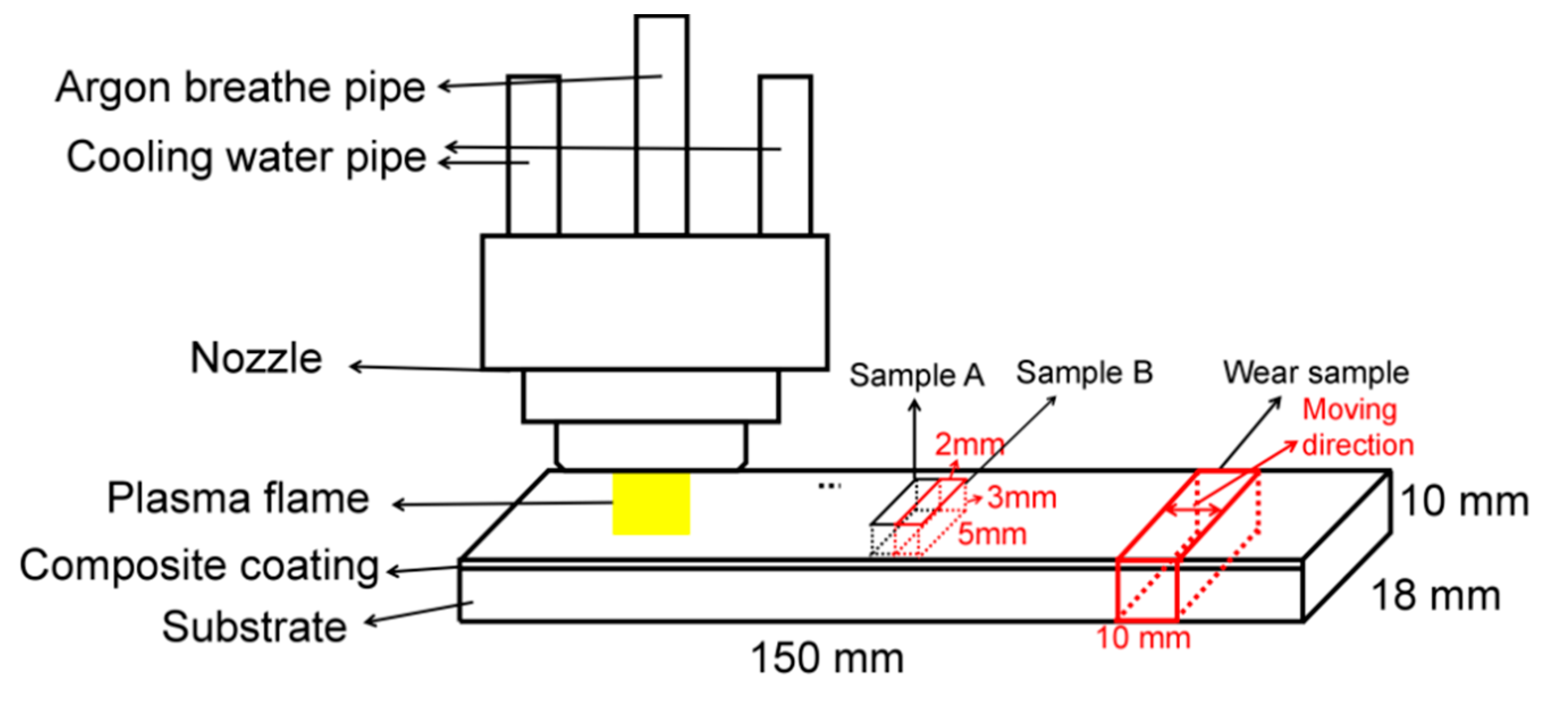
Figure 1. The diagram of plasma cladding treatment.
Coatings 10 00641 g001
Figure 2. Heat treatment process: (a) tempering; and (b) kept at 600 °C for 4 h.
Coatings 10 00641 g002
Figure 3. Schematic diagram of wear test process.
Coatings 10 00641 g003
Figure 4. XRD patterns of quenched M2 high-speed steel and cladding layer.
Coatings 10 00641 g004
Figure 5. The SEM of longitudinal-sectional microstructure of cladding layer: (a) microstructure of cladding layer; (b) magnification of the top region; and (c) magnification of the middle region.
Coatings 10 00641 g005
Figure 6. The morphology of dendritic grain and its element distribution.
Coatings 10 00641 g006
Figure 7. The morphology of equiaxed grain and its element distribution.
Coatings 10 00641 g007
Figure 8. SEM image of plasma cladding coating after tempering: (a) the top region of tempered coating; (b) the detailed morphology.
Coatings 10 00641 g008
Figure 9. EDS mapping analysis results of coating.
Coatings 10 00641 g009
Figure 10. TEM image of plasma cladding coating and selective diffraction.
Coatings 10 00641 g010
Figure 11. EDS line analysis results of plasma cladding layer.
Coatings 10 00641 g011
Figure 12. Schematic diagram of redistribution of elements.
Coatings 10 00641 g012
Figure 13. Hardness of cladding layer: (a) the hardness of tempered sample; (b) the hardness after holding at 600 °C for 4 h.
Coatings 10 00641 g013
Figure 14. Coefficient of friction of cladding layer.
Coatings 10 00641 g014
Figure 15. The 3D morphology and SEM image of the worn surface under load of 50 N: (a) M2 high speed steel; (b) the cladding layer was not tempered; (c) the cladding layer was tempered at 400 °C; and (d) the cladding layer was tempered at 600 °C.
Coatings 10 00641 g015
Figure 16. Wear rate of cladding layer.
Coatings 10 00641 g016
Table 1. Chemical composition of M2 high steel (wt.%).
CCrWMoVSiMnPSFe
0.78–0.883.75–4.505.50–6.754.50–5.501.75–2.200.20–0.450.15–0.40<0.03<0.03balance
Table 2. Chemical composition of point (wt.%).
Element PointCVCrFeNiMoW
Point A2.731.353.8467.7817.283.863.16
Point B8.884.405.8446.8410.6611.2512.13
Point C8.862.896.0553.1011.128.659.33