Article

Diamond-Like Carbon Films with Low Internal Stress by a Simple Bilayer Approach

1
SANNO Co., Ltd., Yokohama 223-0052, Japan
2
Department of Materials Science, Technische Universität Darmstadt, 64287 Darmstadt, Germany
*
Author to whom correspondence should be addressed.
Coatings 2020, 10(7), 696; https://doi.org/10.3390/coatings10070696
Submission received: 7 June 2020 / Revised: 5 July 2020 / Accepted: 17 July 2020 / Published: 19 July 2020
(This article belongs to the Special Issue Synthesis and Characterization of Diamond-Like Carbon Composite Films)

Abstract

:
Amorphous carbon films with a high hardness usually suffer from high internal stress. To deposit films with a hard top surface but reduced internal stress, a simple bilayer approach was used. Films were prepared by plasma source ion implantation, using only hydrocarbon precursors. The single layer with the highest hardness (deposited by a low direct current (DC) voltage and radio frequency (RF) generation of the plasma) has the highest internal stress with more than 3.5 GPa. By adding an interlayer with a lower hardness, the resulting stress of the bilayer film can be reduced to below 1.4 GPa while maintaining the high hardness of the top layer. By avoiding metallic interlayers or dopants within the films, the deposition process can be kept simple and cost-effective, and it is also suitable for three-dimensional samples.

1. Introduction

One of the main applications of amorphous carbon films is as protective coating (e.g., for tribological applications). This requires strong adhesion of the films in combination with a high hardness to be able to withstand the forces involved and to ensure a long-term wear resistance. The hardness of the films depends on the amount of sp3-bonded carbon, which can be influenced by the deposition parameters [1]. A high sp3 content of the film is equivalent to a high hardness [2,3,4] but also to high internal stress of the film [5], which might lead to adhesion failure and delamination.
The stress depends on three different contributions: thermal, intrinsic and extrinsic stress [6]. The coefficient of thermal expansion (CTE) of amorphous hydrogenated films falls into the range of the average CTE of graphite and the CTE of diamond; it depends on the sp3 content of the film [7]. To avoid the thermal stress of the film, it should be deposited at room temperature or onto a substrate with the same thermal expansion coefficient. However, the application might not allow a free choice of the substrate material. Furthermore, a deposition method that involves higher temperatures might be chosen because it is favorable in some other respect, such as high sp3 content, high deposition rate, etc. The energy transfer of the particles, which hit the surface during the deposition process, determines the intrinsic stress value. For a higher hardness, a certain energy amount is required [1]. Extrinsic stress is caused by external factors (i.e., interactions between film and environment).
Since internal stress is inherent in hard diamond-like carbon (DLC) films, some countermeasures have been developed, namely (a) thermal annealing, (b) the addition of dopants to the DLC film and (c) the addition of one or more interlayers between substrate and DLC film. Annealing up to 600 °C, even for a few minutes, as performed in ref. [8], or for several hours at 250 °C [9] is not feasible for all substrates and all DLC films. Dopants that are added for the reduction of compressive internal stress are mostly metals, such as Ti, W, Cr and Nb [10,11]. Dopants usually change other film properties, too. They can decrease the hardness [12,13] or increase the roughness [14] of the film. The use of metallic dopants might pose a contamination risk by metal release from the film. If a metal source, such as a magnetron sputter source or an arc source, is required, this also increases the experimental expenditure. Additionally, it is difficult to coat non-flat samples homogeneously with a metal source because virtually all metal sources are line-of-sight techniques. Techniques that are more appropriate to treat a sample from all sides, such as plasma source ion implantation (PSII), use charged particles that are generated all around the sample (i.e., the sample is immersed in plasma [15,16]).
Interlayers can range from simple metallic layers (e.g., Ti, Ni or Cr [17]), to a Ti/TiN/TiCN/TiC interlayer configuration [18] or a mixed substrate/DLC layer with a compositional gradient [19]. Frequently, the sequence of interlayer and DLC film is repeated (e.g., as Ti or TiC and DLC multilayers [20,21], WC and DLC multilayers [22] or (Cr, N)-DLC and DLC multilayers [23]). The same concerns about contamination risk and experimental expenditure, as mentioned above, apply.
Since the properties of DLC films can be influenced by the deposition conditions, a straightforward solution is the deposition of more than one DLC layer, providing each DLC layer with different properties. The interlayer here is thus also a DLC layer, namely a softer one with a higher sp2 content and hence lower internal stress. In most reports, the sequence of soft and hard DLC layer was repeated (e.g., two periods [24], three periods [25], four periods [26], 2–8 periods [27], 10 periods [28], 30 periods [29], and even up to 2000 periods [30]).
Here, we selected the simplest approach possible to investigate its effectiveness: a DLC bilayer was deposited (i.e., one softer interlayer and one harder film on top; 1 period). In total, this bilayer approach should result in a lower internal stress of the whole DLC film while keeping the higher hardness of the outer layer. To investigate the influence of the deposition conditions, several experimental conditions were varied: three different source gases (methane (CH4), acetylene (C2H2), toluene (C7H8)) were used, a PSII process was run using a direct current (DC) and a pulse voltage, with and without running an additional radio frequency (RF) source. The hardest of all deposited layers was selected and used for the bilayer experiment. By avoiding the use of metals and limiting the precursors to hydrocarbon gases, the coating of three-dimensional samples by low stress layers would be feasible.

2. Materials and Methods

The samples were coated in a commercial PSII apparatus (YAMABISHI Corporation, YHPG-25K-10ATR, Tokyo, Japan). A schematic of the setup can be found in [31]. Strips of silicon wafer (100 orientation, 5 cm long, 1 cm wide, 725 µm thick) were placed on a horizontal sample holder, which was connected to a high voltage source. As a pretreatment, the silicon was implanted for 120 min, using methane gas (99.9% purity) with a pressure of 1 Pa and a high voltage pulse of −18 kV with a repetition rate of 1 kHz and a pulse length of 10 µs. The high voltage ignited the plasma. This pretreatment generates a gradient layer of implanted carbon and hydrogen, which improves adhesion of the following layer [32,33]. For the deposition of the DLC layer, either a DC (−0.5, −1, −1.5 or −2 kV) or a pulse voltage (−18 kV, 100 Hz repetition rate, 100 µs pulse length) was used. In case that both voltages were superposed [34], the resulting maximum voltage (DC and pulse together) was −18 kV (i.e., when the DC voltage was increased, the pulse voltage was decreased by the same amount). In some experiments, the plasma was generated by an additional plasma source. An electrode plate was placed a 10 cm distance from the sample holder with parallel configuration. This plate was connected to an RF power supply via a matching box. The RF signal (power of 100 W) generated a plasma. In all cases, the gas pressure during deposition was about 2.1 Pa. The purity of the acetylene and the toluene was 99.5%. In the case of the bilayer deposition, the layers were deposited successively, with, at most, only a short interruption of the deposition process (duration about 1 min) to adjust the experimental parameters for the deposition of the second layer. When possible, the experimental conditions were changed gradually. In all cases, the flow of the process gas was not interrupted. The deposition time of a single DLC layer was 30–180 min.
The surface morphology of the samples was investigated by scanning electron microscopy (SEM, JEOL JSM-6400, Tokyo, Japan). The surface roughness was measured by scanning probe microscopy (SPM, Nanoscope III, Digital Instruments, Santa Barbara, CA, USA), scanning over an area of 1 µm × 1 µm. Raman spectra in the range of 600–2000 cm−1 were measured with a Horiba LabRAM HR800 instrument (Bensheim, Germany) using a laser with a wavelength of 514 nm. The relative hydrogen content of the samples was derived from depth profiles measured by secondary ion mass spectrometry (SIMS, Cameca ims 5f, Courbevoie, France) with Cs primary ions of 5.5 keV energy, detecting positive ions in the form of cesium clusters. The resulting intensity ratio CsH+/CsC+ was compared to one of a standard sample with a hydrogen content of 19 at.% [35], as determined by elastic recoil detection analysis (ERDA, measurement conditions were the same as outlined in [36]). The hardness of the samples was measured by a nanoindenter (Hysitron, Minneapolis, MN, USA) with a Berkovich indenter and a maximum load of 200 µN. The friction coefficient was determined with a ball-on-disc test (CSEM Standard Tribometer, Peseux, Switzerland), using a tungsten carbide ball of 6 mm diameter with 2 N force and a speed of 10 cm/s. Measurements were done at room temperature and about 30% humidity. The internal stress was determined by measuring the bending of the substrate with a profilometer (Dektak 3, Santa Barbara, CA, USA), using the Stoney equation [37] for the evaluation. Profilometry was also used to measure the film thickness.

3. Results

The film thickness of the single DLC films is in the range of 90 nm to 1.4 µm. As shown in Figure 1, this corresponds to a deposition rate between 0.045 and about 0.6 µm/h. It depends on the type of precursor gas, the DC voltage and the application of high voltage pulses and RF power.
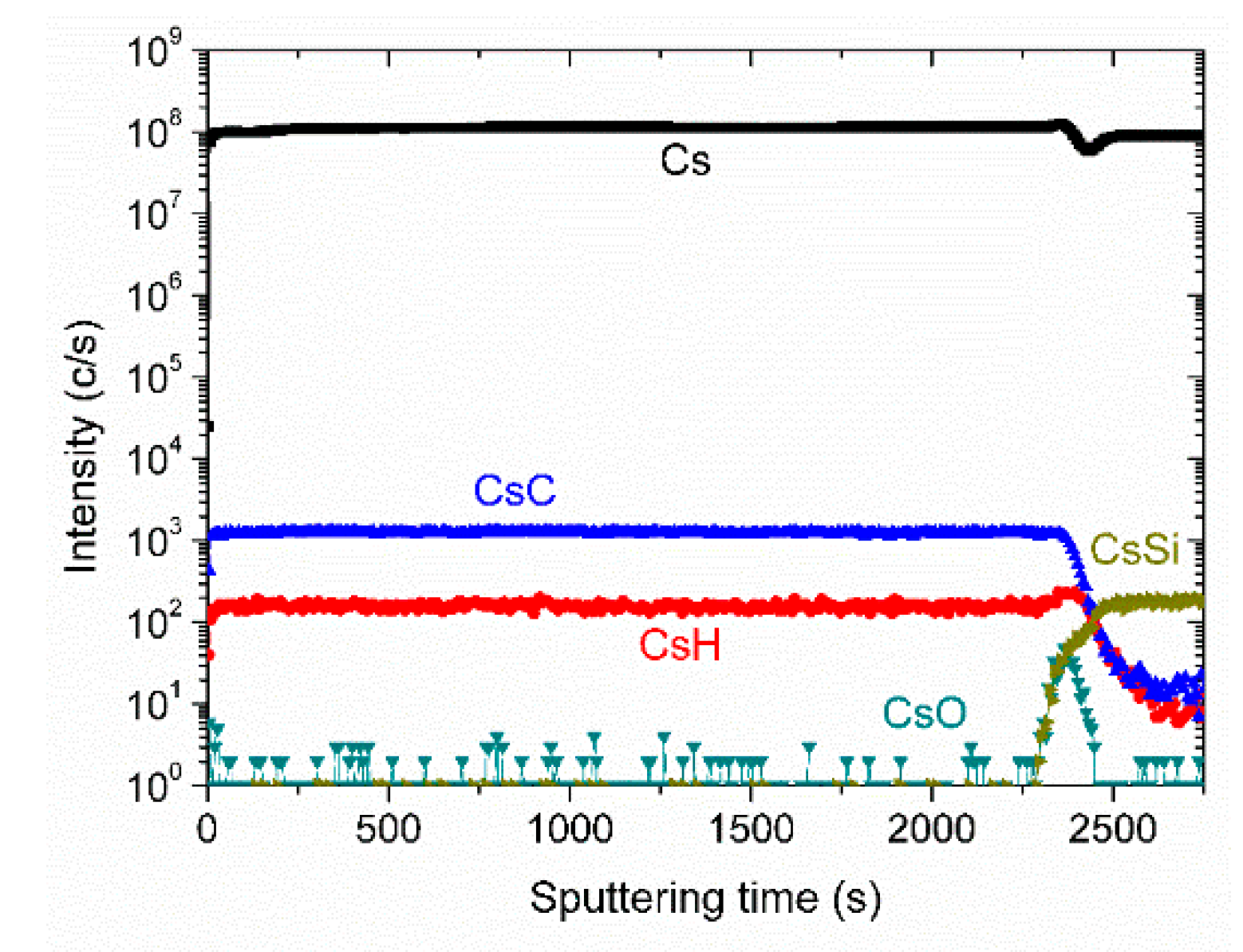
All film surfaces appeared smooth in the SEM images, with no discernible surface features. The film composition is homogeneous with depth. A SIMS depth profile is shown in Figure 2. Both main components, C and H, are visible. Oxygen occurs only at the interface. The large Cs signal is caused by the implanted Cs primary ions that are used for sputtering.
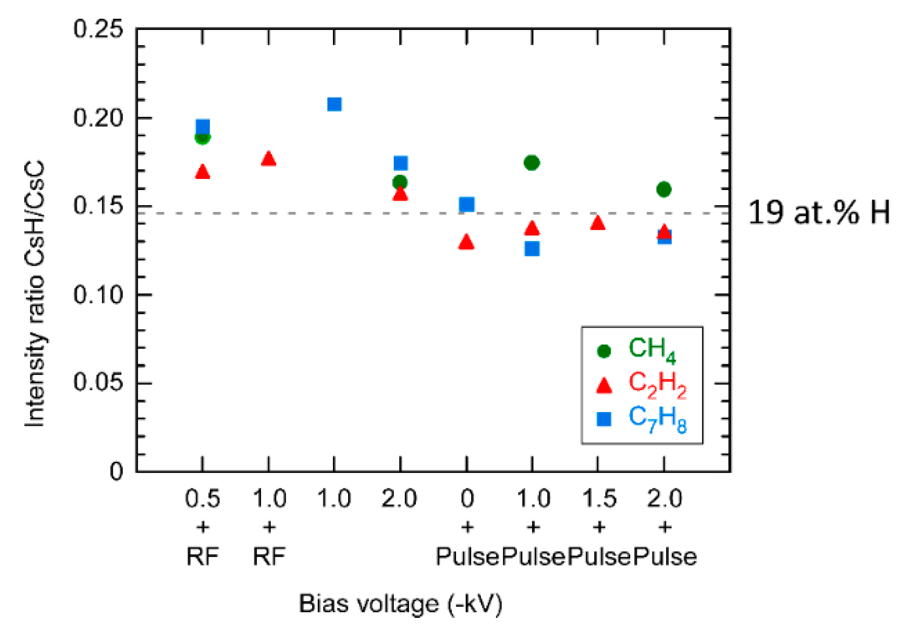
The relative hydrogen content of the samples was derived from the ratio of the CsH+ and the CsC+ signals, CsH+/CsC+, in the SIMS depth profiles. Intensity ratios of Cs clusters are more similar to concentration ratios than the intensity ratios of simple ions (e.g., H+/C+) [38]. As a comparison, the Cs cluster ratio of a sample that contains 19 at.% hydrogen is indicated in Figure 3. Samples that were prepared with a DC voltage or with a DC voltage plus an RF signal show higher hydrogen contents than the standard sample. The use of a pulse voltage (with or without a DC voltage) results, on average, in lower hydrogen contents, around 19 at.%, with a higher influence of the original hydrogen content of the precursor. Here, the samples prepared with CH4 show a higher hydrogen content.
The Raman spectra show the features typical for amorphous carbon [39] (i.e., the D-peak at around 1330 cm−1 and the G-peak at around 1550 cm−1). The preparation conditions influence the intensity ratio ID/IG. From Figure 4 it is evident that the ratio (evaluation based on the peak areas) increases with bias voltage. In most cases, the ID/IG ratio is higher when C7H8 is used and lower when CH4 is used as a precursor.
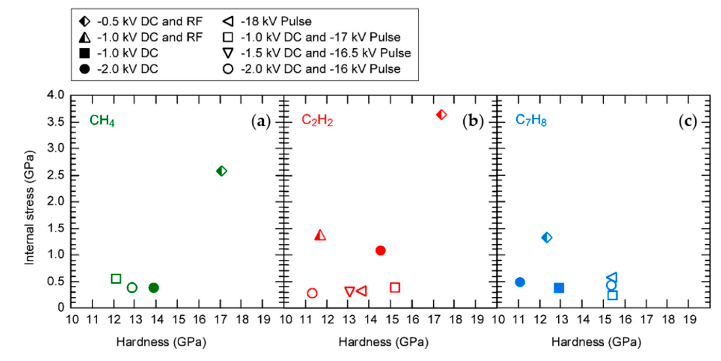
Figure 5 shows the hardness of the layers vs. their internal stress. Most stress values are below 1.5 GPa. Nearly all samples prepared by either a pure DC voltage or by a superposed DC and pulse voltage have a low internal stress, with values around 0.5 GPa. Only when a DC voltage is combined with an RF signal, the resulting film stress is much higher, with 3.65 GPa for the sample prepared using acetylene (C2H2). This is also the hardest sample with a hardness of 17.4 GPa.
As noted above, the highest hardness is connected with the highest internal stress. This sample was selected for the bilayer experiment. The bilayer sample consisted of a 342 nm thick interlayer, prepared with a −2 kV DC voltage and neither RF nor pulse voltage. This condition produces a layer, which—deposited as a single layer—results in a moderate hardness of 11.3 GPa but also a low internal stress of less than 0.3 GPa. As the top layer of the bilayer sample, a 172 nm thick layer was deposited, prepared with the conditions that produced the layer with the highest hardness (i.e., a −0.5 kV DC voltage combined with an RF signal). The bilayer sample had a considerably reduced internal stress of 1.37 GPa while maintaining the hardness of the top layer (measured as 18.3 GPa), as shown in Figure 6.
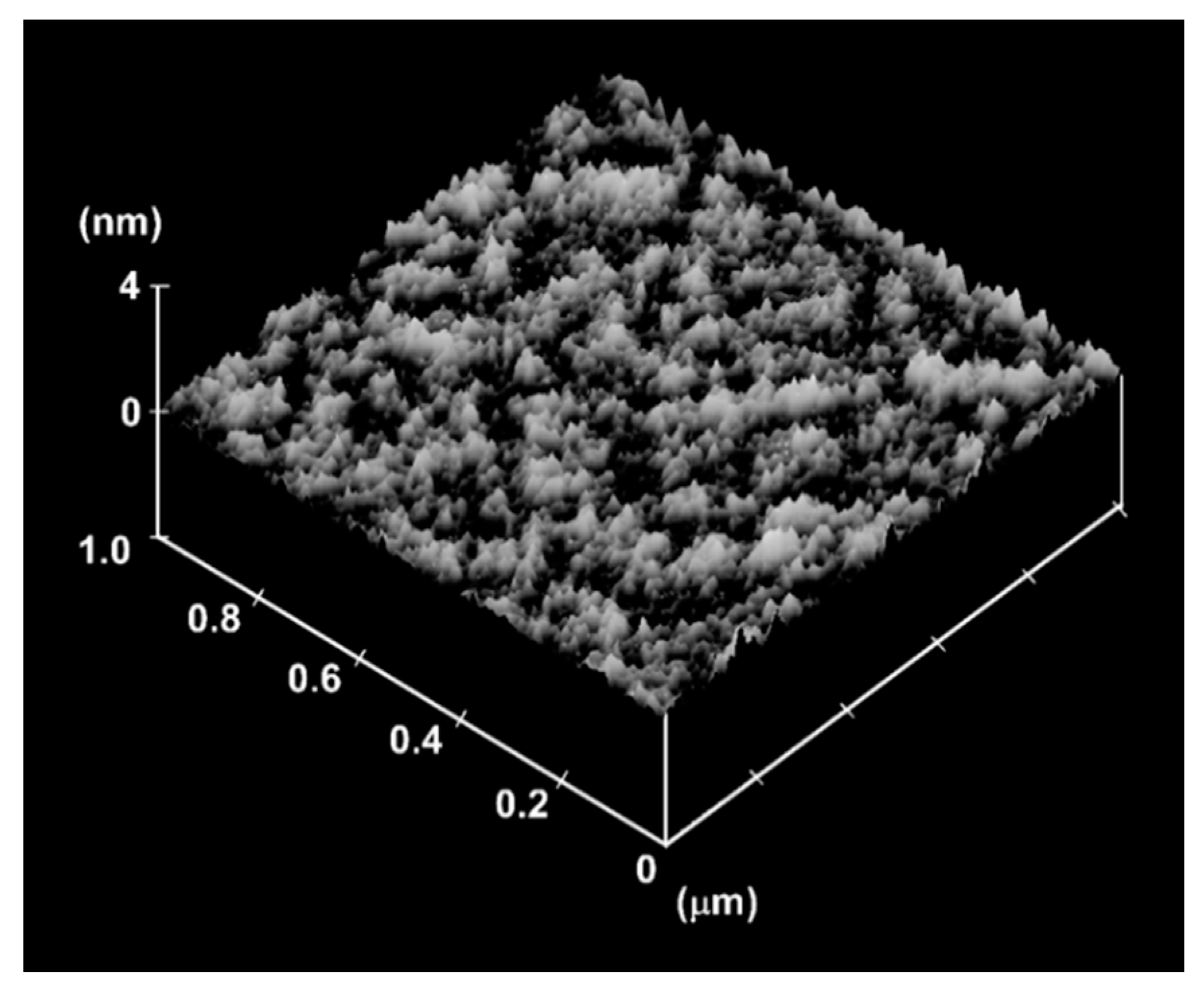
The surface of the bilayer sample as measured by SPM is very smooth, as shown in Figure 7. The obtained average surface roughness Ra is 0.17 nm.
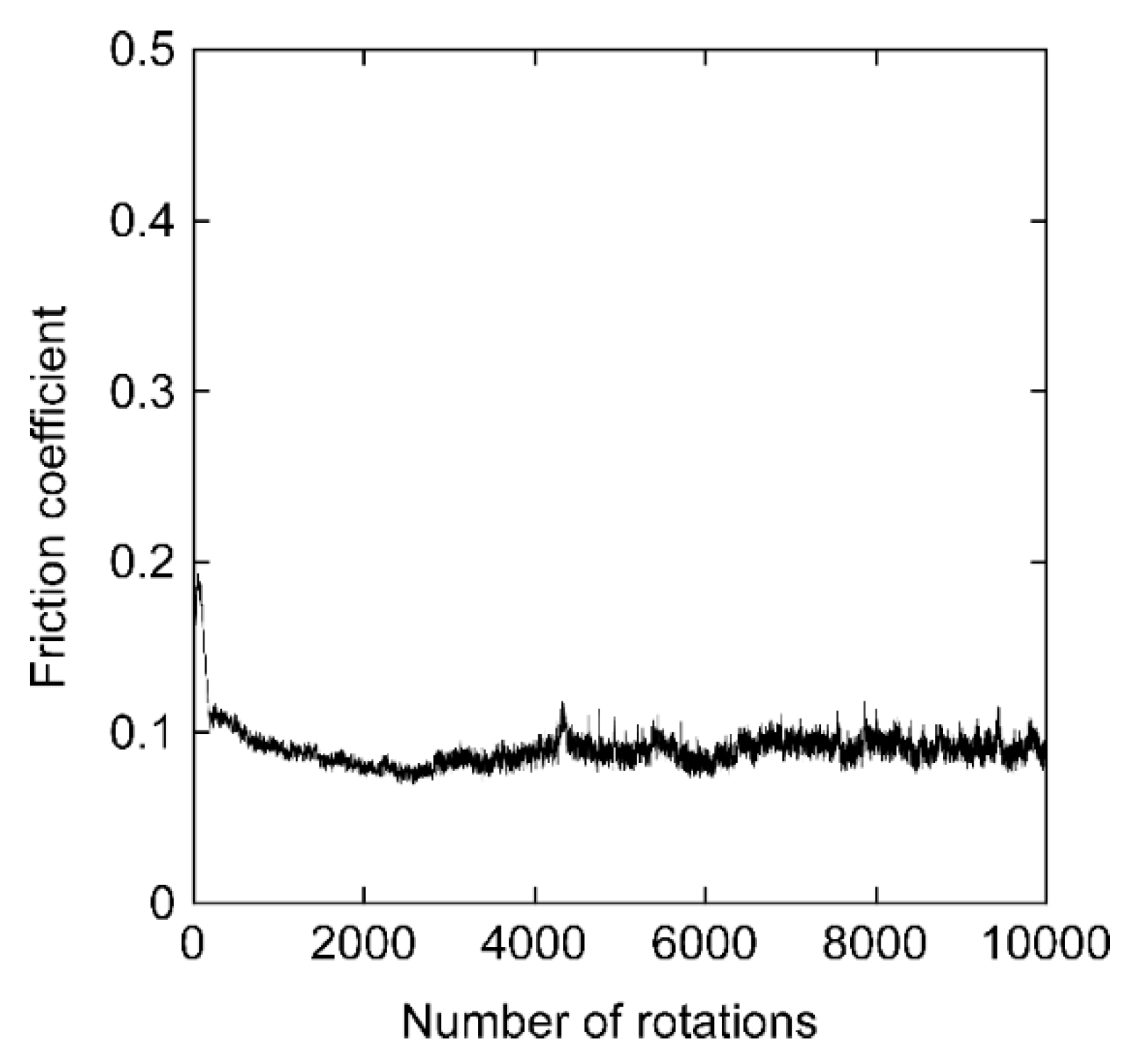
The friction coefficient of the sample, shown in Figure 8, is slightly lower than 0.1, which is a typical value for DLC films. The bilayer did not delaminate during the tribology experiment.

4. Discussion

The deposition rate is lowest when CH4 is used and highest when C7H8 is used. It depends on several factors (e.g., the ionization potential of the molecule, the fragmentation pattern and the ion energy per C atom [1]). CH4 tends to form only an implantation layer under certain experimental conditions [33]. An additional plasma source (i.e., the RF source), should generally increase the deposition rate because of the constantly produced ionized particles. However, here no obvious increase could be noted. As was found before, a lower RF power is more effective in this regard [31]. Furthermore, a low DC voltage of as little as −0.5 kV was combined with the RF signal. The latter leads to a significant variation in the effective ion energy of the particles accelerated towards the substrate [40]. If no RF source is used (i.e., if the plasma is ignited by the voltage applied to the sample), the plasma generation and the deposition are coupled [16]. A change in the applied voltage will invariably influence the intensity and composition of the plasma [41]. An increase in the bias voltage, either by increasing the DC voltage or by superposing a pulse voltage, increases the plasma density and thus the deposition rate. For the superposed voltage, the increase in the DC voltage, with a concurrent equivalent lowering of the pulse height, leads to a higher deposition rate because of the higher duty cycle of the DC voltage. The latter is always present, whereas the pulse is only switched on for 1% of the time.
The hydrogen content of the samples is in the range of about 17 to 26 at.%, assuming that a linear interpolation of the content from Figure 3 is valid. This range is the typical one for hydrogen-containing DLC films [41,42,43]. Comparing Figure 3 and Figure 4, a higher hydrogen content coincides with a lower ID/IG ratio. The latter can be interpreted as a higher sp3 content of the samples [39,44]. Increasing the DC bias voltage or superposing a pulse voltage deposits more energy into the sample, thereby increasing the ID/IG ratio. When using an RF signal, the ID/IG ratio for the sample prepared by C7H8 is particularly higher than the values for the samples prepared by the other precursors. This might indicate that some of the original sp2 rings of the C7H8 molecules survived the deposition process. This would explain the much lower hardness value of the sample, as seen in Figure 5. The other two samples prepared in this way (but with the CH4 and the C2H2 precursors, respectively) show a much higher hardness. Considering the argument mentioned above that the RF signal influences the ion energy, it looks like this energy is more appropriate to achieve a higher sp3 content and a harder film for those two precursors. The optimal value for this is about 100 eV per C atom [1]. The hardness of all films is in the typical range of 10–20 GPa for hard amorphous hydrogen-containing carbon films [1].
The internal stress of most of the films is below 0.5 GPa. The gradient deposited via the initial CH4 implantation combined with the generally low deposition temperature of the PSII technique [16] is an effective way to produce low-stress films with most of the deposition conditions. For those films, there is no need to introduce a stress-lowering interlayer. In the few cases where the internal stress of a film is higher than 1.5 GPa (i.e., when using the additional RF signal), the use of the softer DLC interlayer can lower this stress considerably. Here, the preparation of the bilayer sample reduced the internal stress of the hardest film to a level below 1.4 GPa. Other publications of the internal stress of multilayer DLC samples gave the following results: 5–7 GPa stress at 13.5 to 24.4 GPa hardness [24]; 4.5 GPa stress at 27 GPa hardness [25]; 1.9 to 3.1 GPa stress at 23 to 31 GPa hardness [27]; 1.4 to 3.5 GPa stress at 15.4 to 25.7 GPa hardness [28]; 2.5 GPa stress at 19 GPa hardness [29]. Compared with those values, the achieved result of 1.37 GPa stress at 18.3 GPa hardness proves the effectiveness of the simple bilayer configuration. The film thickness used here is in the typical range for films deposited by PSII. The thickness ratio of soft and hard layer was 2:1. A variation in this ratio would influence the resulting residual stress. Xu et al. showed [24] that 1:1 and 1:2 ratios lead to a higher residual stress.
In addition, the bilayer film prepared by PSII is very smooth, and its friction coefficient falls into the common range of 0.05 to 0.1 [45] for hydrogen-containing DLC films. As explained in the introduction, this process would be applicable to non-flat samples and also, because of the easy scale-up capabilities of the technique, to samples with a large surface area.

Author Contributions

Conceptualization, K.B.; investigation, K.B., R.H. and S.F.; resources, K.B. and W.E.; data curation, K.B. and R.H.; writing—original draft preparation, S.F.; writing—review and editing, R.H. and K.B.; visualization, R.H. and S.F.; supervision, K.B.; project administration, W.E. All authors have read and agreed to the published version of the manuscript.

Funding

This research received no external funding.

Conflicts of Interest

The authors declare no conflict of interest.

References

  1. Robertson, J. Diamond-like amorphous carbon. Mater. Sci. Eng. R Rep. 2002, 37, 129–281. [Google Scholar] [CrossRef] [Green Version]
  2. Demichelis, F.; Pirri, C.F.; Tagliaferro, A.; Benedetto, G.; Boarino, L.; Spagnolo, R.; Dunlop, E.; Haupt, J.; Gissler, W. Mechanical and thermophysical properties of diamond-like carbon (DLC) films with different sp3sp2 ratios. Diam. Relat. Mater. 1993, 2, 890–892. [Google Scholar] [CrossRef]
  3. Savvides, N.; Bell, T.J. Hardness and elastic modulus of diamond and diamond-like carbon films. Thin Solid Films 1993, 228, 289–292. [Google Scholar] [CrossRef]
  4. Hatada, R.; Flege, S.; Ashraf, M.N.; Timmermann, A.; Schmid, C.; Ensinger, W. The Influence of preparation conditions on the structural properties and hardness of diamond-like carbon films, prepared by plasma source ion implantation. Coatings 2020, 10, 360. [Google Scholar] [CrossRef] [Green Version]
  5. Wei, C.; Yang, J.-F. A finite element analysis of the effects of residual stress, substrate roughness and non-uniform stress distribution on the mechanical properties of diamond-like carbon films. Diam. Relat. Mater. 2011, 20, 839–844. [Google Scholar] [CrossRef]
  6. Pauleau, Y. Residual stresses in dlc films and adhesion to various substrates. In Tribology of Diamond-Like Carbon Films: Fundamentals and Applications; Donnet, C., Erdemir, A., Eds.; Springer: Boston, MA, USA, 2008; pp. 102–136. ISBN 978-0-387-49891-1. [Google Scholar]
  7. Marques, F.C.; Lacerda, R.G.; Champi, A.; Stolojan, V.; Cox, D.C.; Silva, S.R.P. Thermal expansion coefficient of hydrogenated amorphous carbon. Appl. Phys. Lett. 2003, 83, 3099–3101. [Google Scholar] [CrossRef] [Green Version]
  8. Friedmann, T.A.; Sullivan, J.P.; Knapp, J.A.; Tallant, D.R.; Follstaedt, D.M.; Medlin, D.L.; Mirkarimi, P.B. Thick stress-free amorphous-tetrahedral carbon films with hardness near that of diamond. Appl. Phys. Lett. 1997, 71, 3820–3822. [Google Scholar] [CrossRef]
  9. Zhang, W.; Tanaka, A.; Wazumi, K.; Koga, Y.; Xu, B.S. The effect of annealing on mechanical and tribological properties of diamond-like carbon multilayer films. Diam. Relat. Mater. 2004, 13, 2166–2169. [Google Scholar] [CrossRef]
  10. Sánchez-López, J.C.; Fernández, A. Doping and alloying effects on DLC coatings. In Tribology of Diamond-like Carbon Films: Fundamentals and Applications; Donnet, C., Erdemir, A., Eds.; Springer: Boston, MA, USA, 2008; pp. 311–338. ISBN 978-0-387-49891-1. [Google Scholar]
  11. Bouabibsa, I.; Lamri, S.; Sanchette, F. Structure, mechanical and tribological properties of Me-Doped diamond-like carbon (DLC) (Me = Al, Ti, or Nb) hydrogenated amorphous carbon coatings. Coatings 2018, 8, 370. [Google Scholar] [CrossRef] [Green Version]
  12. Zou, C.W.; Wang, H.J.; Feng, L.; Xue, S.W. Effects of Cr concentrations on the microstructure, hardness, and temperature-dependent tribological properties of Cr-DLC coatings. Appl. Surf. Sci. 2013, 286, 137–141. [Google Scholar] [CrossRef]
  13. Cui, J.; Qiang, L.; Zhang, B.; Ling, X.; Yang, T.; Zhang, J. Mechanical and tribological properties of Ti-DLC films with different Ti content by magnetron sputtering technique. Appl. Surf. Sci. 2012, 258, 5025–5030. [Google Scholar] [CrossRef]
  14. Corbella, C.; Pascual, E.; Oncins, G.; Canal, C.; Andújar, J.L.; Bertran, E. Composition and morphology of metal-containing diamond-like carbon films obtained by reactive magnetron sputtering. Thin Solid Films 2005, 482, 293–298. [Google Scholar] [CrossRef]
  15. Conrad, J.R.; Dodd, R.A.; Worzala, F.J.; Qiu, X. Plasma source ion implantation: A new, cost-effective, non-line-of-sight technique for ion implantation of materials. Surf. Coat. Technol. 1988, 36, 927–937. [Google Scholar] [CrossRef]
  16. Anders, A. (Ed.) Handbook of Plasma Immersion Ion Implantation and Deposition; John Wiley & Sons: New York, NY, USA, 2000; ISBN 0-471-24698-0. [Google Scholar]
  17. Jeon, Y.; Park, Y.S.; Kim, H.J.; Hong, B.; Choi, W.S. Tribological properties of ultrathin DLC films with and without metal interlayers. J. Korean Phys. Soc. 2007, 51, 1124–1128. [Google Scholar] [CrossRef]
  18. Deng, J.; Braun, M. DLC multilayer coatings for wear protection. Diam. Relat. Mater. 1995, 4, 936–943. [Google Scholar] [CrossRef]
  19. Won, Y.J.; Ki, H. Effect of film gradient profile on adhesion strength, residual stress and effective hardness of functionally graded diamond-like carbon films. Appl. Surf. Sci. 2014, 311, 775–779. [Google Scholar] [CrossRef]
  20. Voevodin, A.A.; Walck, S.D.; Zabinski, J.S. Architecture of multilayer nanocomposite coatings with super-hard diamond-like carbon layers for wear protection at high contact loads. Wear 1997, 203–204, 516–527. [Google Scholar] [CrossRef]
  21. Miyake, S.; Shindo, T.; Suzuki, M. Nanomechanical and boundary lubrication properties of titanium carbide and diamond-like carbon nanoperiod multilayer and nanocomposite films. Surf. Coat. Technol. 2013, 221, 124–132. [Google Scholar] [CrossRef]
  22. Pujada, B.R.; Tichelaar, F.D.; Janssen, G.C.A.M. Hardness of and stress in tungsten carbide–diamond like carbon multilayer coatings. Surf. Coat. Technol. 2008, 203, 562–565. [Google Scholar] [CrossRef]
  23. Guo, C.Q.; Pei, Z.L.; Fan, D.; Gong, J.; Sun, C. Microstructure and tribomechanical properties of (Cr, N)-DLC/DLC multilayer films deposited by a combination of filtered and direct cathodic vacuum arcs. Diam. Relat. Mater. 2015, 60, 66–74. [Google Scholar] [CrossRef]
  24. Xu, Z.; Zheng, Y.J.; Jiang, F.; Leng, Y.X.; Sun, H.; Huang, N. The microstructure and mechanical properties of multilayer diamond-like carbon films with different modulation ratios. Appl. Surf. Sci. 2013, 264, 207–212. [Google Scholar] [CrossRef]
  25. Logothetidis, S.; Gioti, M.; Charitidis, C.; Patsalas, P. A new process for the development of hard and stable sputtered amorphous carbon films. Vacuum 1999, 53, 61–65. [Google Scholar] [CrossRef]
  26. Anders, S.; Callahan, D.L.; Pharr, G.M.; Tsui, T.Y.; Singh Bhatia, C. Multilayers of amorphous carbon prepared by cathodic arc deposition. Surf. Coat. Technol. 1997, 94–95, 189–194. [Google Scholar] [CrossRef]
  27. Zhang, W.; Tanaka, A.; Xu, B.S.; Koga, Y. Study on the diamond-like carbon multilayer films for tribological application. Diam. Relat. Mater. 2005, 14, 1361–1367. [Google Scholar] [CrossRef]
  28. Lin, Y.; Zia, A.W.; Zhou, Z.; Shum, P.W.; Li, K.Y. Development of diamond-like carbon (DLC) coatings with alternate soft and hard multilayer architecture for enhancing wear performance at high contact stress. Surf. Coat. Technol. 2017, 320, 7–12. [Google Scholar] [CrossRef]
  29. Li, F.; Zhang, S.; Kong, J.; Zhang, Y.; Zhang, W. Multilayer DLC coatings via alternating bias during magnetron sputtering. Thin Solid Films 2011, 519, 4910–4916. [Google Scholar] [CrossRef]
  30. Lu, X.; Li, M.; Tang, X.; Lee, J. Micromechanical properties of hydrogenated diamond-like carbon multilayers. Surf. Coat. Technol. 2006, 201, 1679–1684. [Google Scholar] [CrossRef]
  31. Hatada, R.; Flege, S.; Ensinger, W.; Baba, K. Deposition of diamond-like carbon films on insulating substrates by plasma source ion implantation. Surf. Coat. Technol. 2020, 385, 125426. [Google Scholar] [CrossRef]
  32. Walter, K.C.; Nastasi, M.; Munson, C. Adherent diamond-like carbon coatings on metals via plasma source ion implantation. Surf. Coat. Technol. 1997, 93, 287–291. [Google Scholar] [CrossRef] [Green Version]
  33. Baba, K.; Hatada, R.; Nakao, S.; Miyagawa, S.; Miyagawa, Y. Miyagawa Formation of diamond like carbon films by plasma source ion implantation from CH4, C2H2 and C6H6. In Proceedings of the 1998 International Conference on Ion Implantation Technology, Proceedings (Cat. No.98EX144), IEEE, Kyoto, Japan, 22–26 June 1998; 2, pp. 1214–1217. [Google Scholar]
  34. Baba, K.; Hatada, R. Deposition of diamond-like carbon films by plasma source ion implantation with superposed pulse. Nucl. Instrum. Methods Phys. Res. Sect. B Beam Interact. Mater. At. 2003, 206, 708–711. [Google Scholar] [CrossRef]
  35. Hatada, R.; Flege, S.; Ensinger, W.; Hesse, S.; Tanabe, S.; Nishimura, Y.; Baba, K. Preparation of Aniline-Based Nitrogen-Containing Diamond-Like Carbon Films with Low Electrical Resistivity. Coatings 2020, 10, 54. [Google Scholar] [CrossRef] [Green Version]
  36. Muguruma, T.; Iijima, M.; Kawaguchi, M.; Mizoguchi, I. Effects of sp2/sp3 Ratio and Hydrogen Content on In Vitro Bending and Frictional Performance of DLC-Coated Orthodontic Stainless Steels. Coatings 2018, 8, 199. [Google Scholar] [CrossRef] [Green Version]
  37. Stoney, G.G.; Parsons, C.A. The tension of metallic films deposited by electrolysis. Proc. R. Soc. Lond. Ser. A 1909, 82, 172–175. [Google Scholar] [CrossRef] [Green Version]
  38. Gao, Y. A new secondary ion mass spectrometry technique for III-V semiconductor compounds using the molecular ions CsM+. J. Appl. Phys. 1988, 64, 3760–3762. [Google Scholar] [CrossRef]
  39. Ferrari, A.C.; Robertson, J. Interpretation of Raman spectra of disordered and amorphous carbon. Phys. Rev. B 2000, 61, 14095–14107. [Google Scholar] [CrossRef] [Green Version]
  40. Chun, S.-Y.; Chayahara, A.; Horino, Y. Development of plasma-based ion implantation (PBII) techniques at Osaka National Research Institute (ONRI). Surf. Coat. Technol. 2001, 136, 32–35. [Google Scholar] [CrossRef]
  41. Ensinger, W. Formation of carbides and diamond-like carbon films by hydrocarbon plasma immersion ion implantation. In Plasma Surface Engineering Research and Its Practical Applications; Wei, R., Ed.; Research Signpost: Trivandrum, India, 2008; pp. 135–178. ISBN 978-81-308-0257-2. [Google Scholar]
  42. Choi, J.; Ishii, K.; Kato, T.; Kawaguchi, M.; Lee, W. Structural and mechanical properties of DLC films prepared by bipolar PBII&D. Diam. Relat. Mater. 2011, 20, 845–848. [Google Scholar] [CrossRef]
  43. Trava-Airoldi, V.J.; Bonetti, L.F.; Capote, G.; Fernandes, J.A.; Blando, E.; Hübler, R.; Radi, P.A.; Santos, L.V.; Corat, E.J. DLC film properties obtained by a low cost and modified pulsed-DC discharge. Thin Solid Films 2007, 516, 272–276. [Google Scholar] [CrossRef]
  44. Tai, F.C.; Lee, S.C.; Wei, C.H.; Tyan, S.L. Correlation between ID⁄IG ratio from visible Raman spectra and sp2/sp3 ratio from XPS spectra of annealed hydrogenated DLC film. Mater. Trans. 2006, 47, 1847–1852. [Google Scholar] [CrossRef] [Green Version]
  45. Grill, A. Review of the tribology of diamond-like carbon. Wear 1993, 168, 143–153. [Google Scholar] [CrossRef]
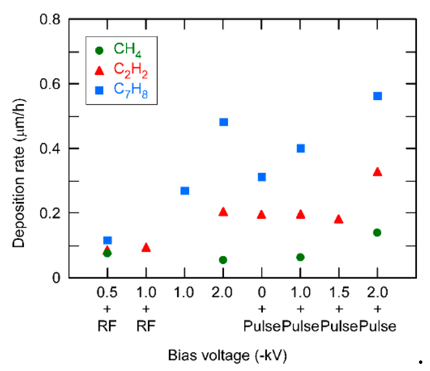
Figure 1. Deposition rates of the single DLC layers prepared with different conditions as indicated. The bias voltage consists of a DC voltage (upper line of the x-axis label) and/or a pulse voltage or an RF voltage (the latter applied at the electrode plate).
Coatings 10 00696 g001
Figure 2. Secondary ion mass spectrometry depth profile of the sample prepared by a −1 kV DC voltage superposed by a −17 kV pulse, using the C7H8 precursor. Shown are positive secondary ion signals.
Coatings 10 00696 g002
Figure 3. Relative hydrogen content of the single DLC layers prepared with different conditions as indicated. The dashed line indicates the intensity ratio of a sample with 19 at.% hydrogen, as determined by elastic recoil detection analysis.
Coatings 10 00696 g003
Figure 4. Intensity ratio ID/IG of the single DLC layers prepared with different conditions as indicated.
Coatings 10 00696 g004
Figure 5. Hardness and internal stress of the samples, for each precursor gas. (a) CH4; (b) C2H2; (c) C7H8. The preparation conditions are indicated by different symbols as listed in the label on top.
Coatings 10 00696 g005
Figure 6. Hardness and internal stress of the samples prepared with C2H2 as precursor gas. The preparation conditions are indicated by different symbols, as listed in the label on top. The arrow indicates the change from a single DLC layer to the bilayer.
Coatings 10 00696 g006
Figure 7. Scanning probe microscope image of the bilayer sample.
Coatings 10 00696 g007
Figure 8. Friction coefficient of the bilayer sample vs. the number of rotations in the tribology experiment.
Coatings 10 00696 g008