Article

The Influence of Preparation Conditions on the Structural Properties and Hardness of Diamond-Like Carbon Films, Prepared by Plasma Source Ion Implantation

Department of Materials Science, Technische Universität Darmstadt, 64287 Darmstadt, Germany
*
Author to whom correspondence should be addressed.
Coatings 2020, 10(4), 360; https://doi.org/10.3390/coatings10040360
Submission received: 26 February 2020 / Revised: 1 April 2020 / Accepted: 3 April 2020 / Published: 6 April 2020
(This article belongs to the Special Issue Synthesis and Characterization of Diamond-Like Carbon Composite Films)

Abstract

:
Diamond-like carbon (DLC) films were prepared from a hydrocarbon precursor gas by plasma source ion implantation (PSII), in which the plasma generation and the film deposition were coupled; i.e., the plasma was generated by the applied voltage and no additional plasma source was used. Several experimental parameters of the PSII process were varied, including the sample bias (high voltage, DC or pulsed), gas pressure, sample holder type and addition of argon in the plasma gas. The influence of the deposition conditions on the carbon bonding and the hydrogen content of the films was then determined using Raman spectroscopy. Nanoindentation was used to determine the hardness of the samples, and a ball-on-disk test to investigate the friction coefficient. Results suggest that films with a lower sp2 content have both a higher hydrogen content and a higher hardness. This counterintuitive finding demonstrated that the carbon bonding is more important to hardness than the reported hydrogen concentration. The highest hardness obtained was 22.4 GPa. With the exception of a few films prepared using a pulsed voltage, all conditions gave DLC films having similarly low friction coefficients, down to 0.049.

1. Introduction

Diamond-like carbon films are very hard with hardness values of more than 80 GPa [1] if the films have a high amount of sp3 bonding and are hydrogen-free [2]. These high hardness films exhibit a low friction coefficient under oil lubrication [3]. At a lower sp3 content, the films are softer [3]. Hydrogenated diamond-like carbon (DLC) films have a much lower hardness as well, typically 10–20 GPa for hydrogen contents up to 40% [4,5], but add the advantages of a smoother surface [6,7], lower internal stress [8] and lower friction coefficients in dry sliding [6,9].
Correlating experimental parameters of DLC film deposition with the resultant chemical and physical film properties is an ongoing task [10,11,12,13,14] that has to consider the specifics of the preparation method and the intended application. In general, for the sample preparation methods that use a gaseous precursor, the hydrogen content of the films can be influenced by the hydrogen to carbon ratio of the precursor gas (e.g., CH4, C2H4, C7H8 or C2H2) [5]. Usually, the hardness of a DLC film decreases with increasing hydrogen content [15,16], which is done by adding a hydrogen-rich gas such as CH4 [7] or H2 [17,18] to the preparation process. DLC films with high hydrogen content (more than 40%) have a hardness of less than 10 GPa [5,17,19]. Incorporation of hydrogen also influences the type of carbon bonding, as seen in Raman spectra of the films [7,17]. The sp3 content of hydrogen-containing DLC films is several tens of percent [5]. The amount varies and depends on the preparation conditions of the film. A medium ion energy increases the sp3 content [20]. Too much energy [21] or a too high temperature [22] promotes graphitic deposition. For films prepared with hydrogen-rich precursors, the sp3 content increases with hydrogen content [18].
Since hydrogen content and carbon bonding are interconnected, they cannot be studied independently. The situation is even more complex when a technique such as PSII is used for the sample preparation. Here, ions of a plasma are accelerated towards a sample that is biased to a high negative voltage [23]. If no additional plasma source (e.g., radio frequency (RF), electron cyclotron resonance (ECR) or inductively coupled plasma (ICP)) is present, i.e., if the plasma is generated by the applied voltage, the plasma generation and the deposition are coupled [24]. Varying the applied voltage influences the composition of the plasma, i.e., the number of ions and molecular fragments of the plasma gas [25]. The composition, in turn, has an effect on the film growth [19]. Further parameters that affect film growth are the type of voltage (DC or pulse), the pressure and the gas composition. It was found that the addition of argon to the plasma gas affects the dissociation degree of a hydrocarbon gas [26] and can enhance the hardness of the films [27]. The type of sample holder has an additional influence. It was shown that a sample holder with a large open area facilitates striking a plasma and increases the deposition rate, thereby altering film properties [28]. This grid-type holder consisted of six concentric rings of steel wire (2 mm wire diameter), which were fixed to two additional wires running from the center of the rings to the outside.
Even though several studies already exist that investigated the connection of deposition conditions and DLC film properties for a variety of different experimental setups, there are nevertheless several reasons to perform the investigation presented here: (1) Most PSII setups use an additional plasma source. However, generation of the plasma by the acceleration voltage itself (by unassisted discharge) is of importance because it is especially suited for applications that demand easy scale-up to the treatment of large areas or many samples at the same time. As described above, PSII without an additional plasma source is a complex process because a change of the acceleration voltage simultaneously changes the plasma. Therefore, results from experimental setups with assisted discharge—or even from non-PSII setups—have a very limited transferability. This also holds true for PSII setups that use an unassisted discharge but a different type of high voltage, such as a bipolar [29] or a superposed [30] pulse. (2) Most other studies focused on the selective variation of only one or two deposition parameters. To get a full picture of the influence of different parameters, the same setup should be used for the investigation. (3) In this investigation, ethylene (C2H4) was used as process gas. Ethylene is more hydrogen-rich than the often-used acetylene (C2H2). Because of its higher hydrogen content, ethylene is a suitable candidate for the investigation of the effect of hydrogen within the films without having to resort to the handling of pure hydrogen. The use of CH4 is no viable alternative due to its considerably lower deposition rate [5]. (4) The grid-type holder was presented only recently as a alternative to a plate-type sample holder [28]. The grid-type holder offers several advantages, e.g., a higher deposition rate and a lower ignition voltage of the plasma, but its effects on some of the film properties investigated here are unknown.
Therefore, several deposition parameters were varied and the effects on the properties of the films produced by PSII with unassisted discharge were investigated. Specifically, two film properties important for most applications, the hardness and the friction coefficient, were determined and correlated with the structural and compositional results.

2. Materials and Methods

Samples were prepared in a homemade PSII setup, using a high voltage applied to the sample holder to ignite the plasma; i.e., no additional plasma source was employed (a schematic of a comparable setup can be found in [31]). The voltage was either a DC voltage (−1.5, −2 or −2.5 kV; HCP 5000-3500, FuG Elektronik, Schechen, Germany) or a pulsed voltage (−10, −15 or −18 kV; RUP 6-25, GBS Elektronik GmbH, Radeberg, Germany) with 40 µs pulse length and 250 Hz repetition rate. The plasma gas was C2H4 with a flow of 6 sccm, controlled by a mass flow controller (MFC; MKS Instruments, Munich, Germany). The process pressure was set to 0.65, 0.7 or 0.8 Pa. In some cases, argon (purity 99.999%) was added with a flow of 0.3 or 0.6 sccm while keeping the same process pressure. The process time was 45–150 min, resulting in film thicknesses between 100 and 700 nm.
Substrates were 10 × 10 mm2 pieces of silicon wafer. They were fixed by small screws to a larger sample holder, which was either a steel plate with 100 mm diameter (plate-type) or a grid-type holder of 92 mm diameter with a large open area. With each experiment, a piece of partially masked silicon was included to facilitate the determination of the film thickness by profilometer measurements (Dektak XT Advanced, Bruker Nano GmbH, Karlsruhe, Germany).
The DLC films were evaluated by Raman spectroscopy (LabRam HR 800; Horiba Jobin-Yvon GmbH, Bensheim, Germany), which is a widely used technique to obtain the detailed bonding structure of DLC films. In the Raman spectra, two broad peaks can be seen, the D-peak around 1330 cm−1 and the G-peak around 1550 cm−1. Both are caused by sp2 sites—the D mode only by carbon rings, the G mode by any pair of sp2 sites. Even though sp3 sites are not directly seen, some correlations of the sp3 fraction with the ratio of the areas of the D- and G-peaks, I(D)/I(G), and with the shift of the G peak position have been observed [5]. A laser with a 633 nm wavelength was used, the only available laser at the time of measurement. The longer wavelength shifts the spectrum to lower wavenumbers and slightly increases the width of the G peak as well as the I(D)/I(G) ratio [32]. The spectra were acquired in the range of 600–2000 cm−1 with an integration time of 25 s. They were fitted with two Gaussian peaks. The hydrogen content of the samples was derived from the Raman spectra. It was shown before that the ratio of the maximum intensity of the G peak, S, and the photoluminescence background, N, can be used empirically to estimate the hydrogen content; i.e., log (N/S) is proportional to the hydrogen content [33]. The relative change of the hydrogen content was confirmed via depth profiles, which were acquired by secondary ion mass spectrometry (SIMS, ims 5f, CAMECA, Courbevoie, France) using cesium primary ions (5.5 kV energy) and detecting cesium cluster ions; i.e., CsC+ and CsH+. Additional depth profiles were recorded with O2+ primary ions to verify the homogeneity of film composition with depth.
The hardness of the films was measured via nanoindentation (iNano, Nanomechanics, Oak Ridge, TN, USA and G200, Keysight Germany GmbH, Böblingen, Germany). Nine indentations were made on each sample with a Berkovich diamond indenter. The maximum indentation depth was about 500 nm. However, experiments were performed applying the continuous stiffness measurement technique, which allows evaluation of the data at any point of the loading curve [34,35]. The hardness was evaluated at about 10% of the specimen’s film thickness to avoid an influence of the substrate.
The friction coefficient was measured with a ball-on-disk test (Standard Tribometer, CSM, Peseux, Switzerland), using a tungsten carbide ball with 6 mm diameter and a force of 1 N. The tests were done at room temperature and 25% relative humidity. The reported friction coefficients are the averages of the results of three experiments for each sample.

3. Results

All DLC films adhered well to the substrate. Because there was no prior cleaning of the substrate before deposition, it may be that ion bombardment of the substrate removed any organic surface contaminations from the substrate during the initial stage of the deposition. Furthermore, the ion energy in the keV range leads to the generation of a gradient distribution within the surface as a result of ion implantation. This gradient promotes adhesion [36]. Most of the samples exhibited a smooth surface, except for the ones prepared by a pulsed voltage of –15 and –18 kV in combination with the grid-type holder. For those samples, a slightly rough surface morphology could be observed in the SEM images (Quanta 200F, FEI, Hillsboro, OR, USA).
The maximum deposition rate was about 10 nm/min for the sample prepared with a −2.5 kV DC voltage at 0.8 Pa pressure, no argon addition, using the grid-type holder. Generally, the deposition rate increased with voltage and gas pressure because of the higher number of ions generated. If the pressure and voltage were kept constant, when argon was added (and ethylene decreased), the deposition rate decreased: fewer hydrocarbons were available for film growth, and the argon thinned the film during deposition by sputtering. DC voltages gave higher deposition rates than pulsed high voltages: although the pulsed voltages had higher values, the duty cycle (1%) was much lower compared to a DC voltage.
To assess the relative sp3/sp2 bonding of the various films, Figure 1 gives the ratio I(D)/I(G) and the full width at half maximum of the G peak (FWHM(G)) as a function of the G peak position for all films. Symbols and colors in Figure 1 give the basic parameters only; a table in the Supplementary Materials (Table S1) gives the process details for each sample (voltage, gas pressure and Ar flow). Specifically (1) round symbols are used for a DC voltage, square symbols for a pulsed high voltage; (2) blue color denotes the addition of argon; and (3) open symbols represent the use of a grid-type holder, whereas filled symbols represent the use of the plate-type holder.
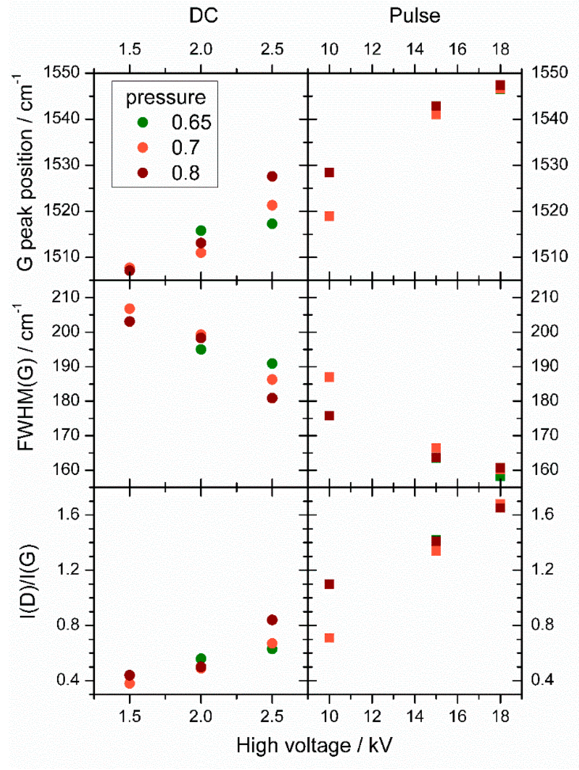
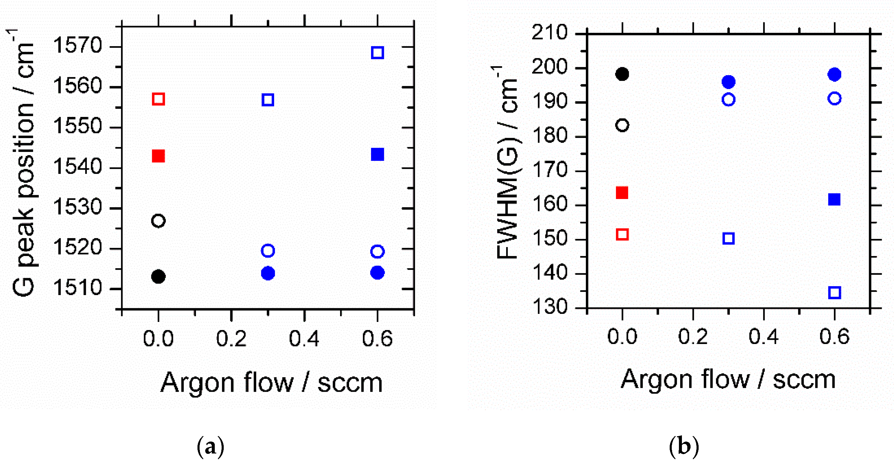
The I(D)/I(G) ratio increases almost linearly with G peak position. Simultaneously, the FWHM(G) decreases linearly with G peak position. A clustering of the different symbols in certain areas of the graphs can be noted. Some general trends of the influence of deposition parameters are shown in Figure 2. A higher voltage shifts the G peak position to higher values and leads to a narrower G peak and a higher I(D)/I(G) value. This effect can further be influenced by increasing the gas pressure during deposition. For a DC voltage, the values spread more at higher voltages and different pressures, whereas they converge at higher pulse voltages. The influence of argon addition and of the use of a grid-type holder is shown in Figure 3. With a grid-type holder, both the G peak position and the I/D)/I(G) value increased, whereas the FWHM(G) decreased. Argon addition enhances these effects when a pulsed voltage is used.
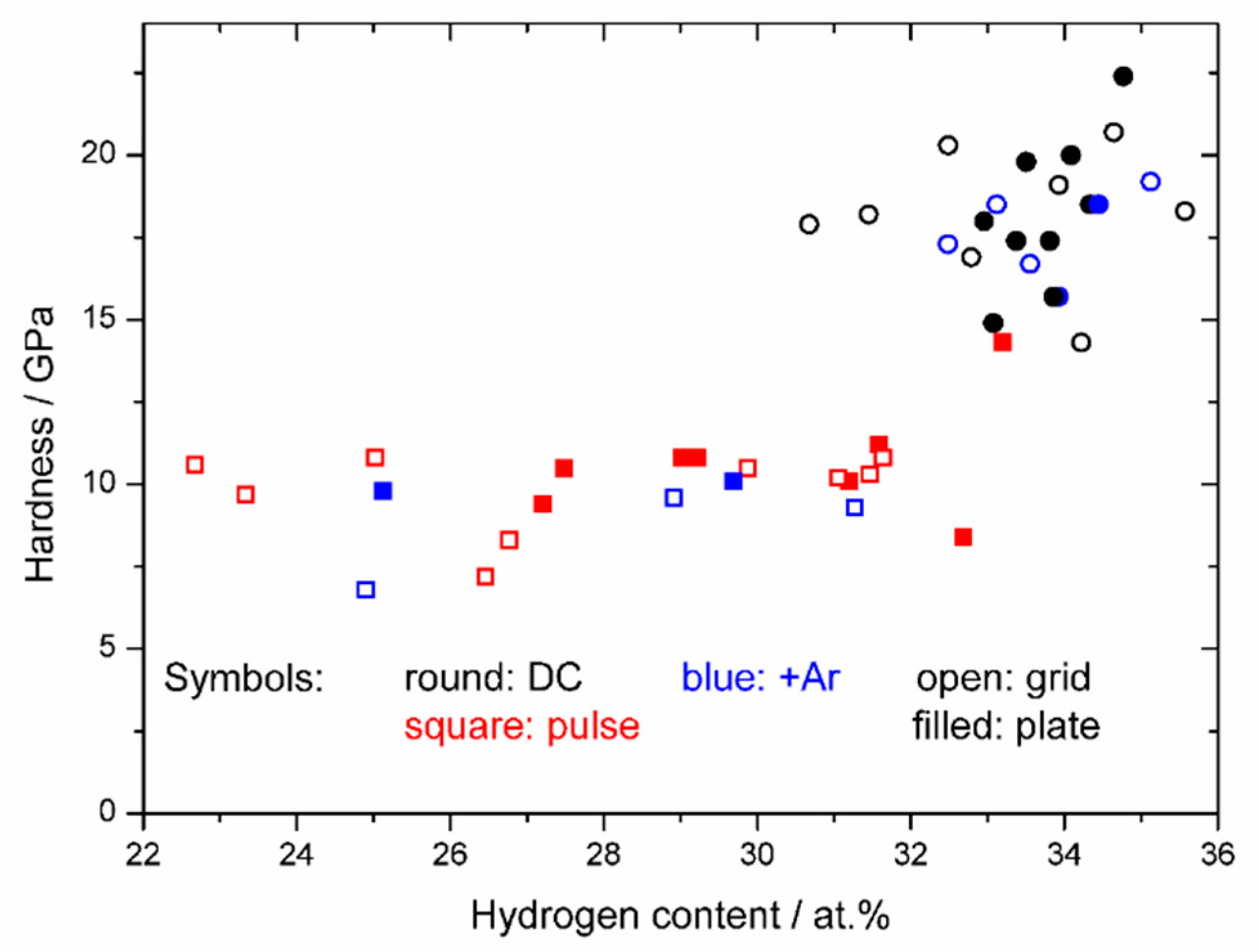
Figure 4 (hardness vs. H content) demonstrates that deposition parameters that promote a higher hardness also increase the hydrogen content. The samples prepared by a DC voltage cluster in the upper right corner of the graph; i.e., they have the highest hardness, above 14 GPa, and hydrogen contents above 30 at.%. Samples prepared by a pulsed high voltage possess a lower hydrogen content (22.7 up to 33 at.%, with most samples below 32 at.%). Nearly all of those samples have a hardness below 12 GPa, with one exception at ~14.5 GPa.
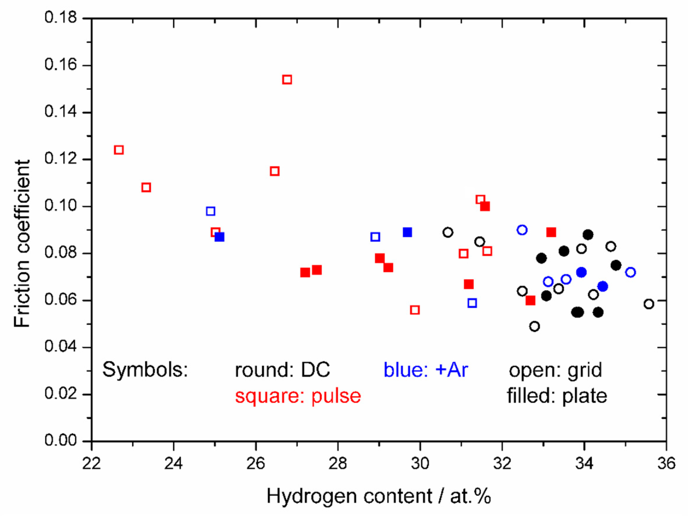
Figure 5 gives the measured friction coefficient vs. the hydrogen content of each film. The values of the friction coefficient represent the steady-state value, i.e., the one reached after a break-in period, which is characterized by a continuously decreasing friction coefficient. Most of the friction coefficients are below 0.1. There may be a slight increase in friction coefficient with decreasing H. The film with the highest friction coefficient (0.154) was fabricated using –18 kV and a grid-type holder and has a noticeably rough surface under SEM. The lowest friction coefficients are primarily at the highest H content (Figure 5) and are generally films prepared using a DC voltage.

4. Discussion

Experimental conditions during the film preparation influence the bonding and hydrogen content. For hydrogen-containing amorphous carbon (a-C:H) films, a high I(D)/I(G) value and a high value of the G peak position are indicative of a low sp3 fraction [5]. Another sign of graphitization is a lower FWHM(G) [33,37]. Films with a high sp2 fraction can thus be found in the upper right corner of the upper graph of Figure 1 and in the lower right corner of the lower graph. An increasing high voltage, a higher gas pressure, argon addition and the use of a grid-type holder promote the graphitization by increasing the amount of energy deposited onto the sample per time unit. A higher voltage generates more ions and increases the ion energy. A higher gas pressure provides a higher number of gas particles that can be ionized. The argon addition causes a higher energy deposition per particle [38], since Ar is only a single atom, whereas C2H4 consists of six atoms. The energy gained from the ion acceleration (at the same bias voltage) is upon impact distributed amongst the individual atoms of the molecule according to their masses. The momentum of the Ar ion is higher too, which might help with removing more sp2 carbon relative to sp3 carbon. With the grid-type holder, more ions are generated and fewer are lost hitting the sample holder [28]. A higher amount of deposited energy leads to a higher sample temperature, promoting graphitization [33].
Conditions that result in a lower sp2 content lead to a higher hydrogen content. Hydrogen saturates the C=C bonds, converting them to sp3 =CH2 and ≡CH sites [5]. The promotion of graphitization can be achieved by the sample bias (high voltage), for instance. As the voltage is lowered, the samples are more diamond-like and less graphite-like. In contrast to other studies [33,37], we did not find a polymer-like carbon area with G peak positions below 1540 cm−1 and a simultaneously decreasing FWHM(G). The difference is—apart from the use of various experimental layouts—that those authors continually lowered the voltage, keeping all the other conditions constant, whereas we switched from a pulsed to a DC voltage for the range of lower voltages. This is necessary for PSII in the configuration used here because the deposition rates are very low for a low pulsed voltage. However, we could show that the range of the more DLC-like samples can thus be extended into the area of G peak positions below 1540 cm−1. The hydrogen contents cover a similar range (20–35 at.%) as reported by Choi et al. [33], who used a precursor gas with a lower relative hydrogen amount (C7H8), which explains why our lowest value (22.7 at.%) is a few at.% higher than their lowest values.
The hardness values of most samples fall into the range common for a-C:H samples; i.e., 10–20 GPa [5]. Use of a DC voltage in the preparation leads to a hardness that reaches the upper end of the typical range (~20 GPa). Those samples have a higher hydrogen content but also a higher sp3 fraction. As mentioned in the introduction, a higher hydrogen content can be found to decrease the hardness. But here, the carbon bonding seems to be more important than the hydrogen content. We speculate that a further increase in hydrogen content and in sp3 bonding is unlikely to result in harder films, as films with hydrogen contents above 40 at.% in other studies are polymer-like and thus softer [39].
The addition of argon increased the hardness of the films more often than not when DC voltages were used. When pulsed voltages were used, the added argon decreased the hardness. Yang et al. reported [27] an increase of the hardness of the films with argon addition. As they employed an additional plasma source and investigated the deposition in micro-holes, the conditions were not entirely comparable to ours (flat samples and no additional plasma source). Paul et al. noted a higher G peak position and a narrower FWHM(G) but a lower I(D)/I(G) with increased argon addition for DLC films prepared by capacitively coupled plasma CVD [40]. This is further evidence that effects of argon addition are specific to the deposition conditions.
Most samples showed friction coefficients below 0.1 regardless of the deposition conditions. Figure 5 suggests a trend of lower friction coefficients with higher hydrogen contents and thus higher sp3 contents; i.e., for harder films. The values of the samples prepared by a DC voltage overlap more with the ones of those prepared by a pulsed voltage than the hardness values did. This occurred because a tribology experiment is a dynamic process in which abrasive, adhesive and shearing components play a role [41], which are usually influenced by more than one film property. Nevertheless, for DLC films, the hydrogen content is of importance. The low friction coefficient (that is reached after a break-in period with continuously decreasing friction coefficient) is thought to be related to the release of hydrogen and the graphitization in the tribolayer [42]. The higher hydrogen content is more important in this context than the amount of initially present sp3-bonded carbon; i.e., the inherent hydrogen is required for a low friction coefficient. This is demonstrated by the fact reported in literature [6] that hydrogen-free carbon films with a high amount of sp3 possess higher friction coefficients.
Comparisons of friction coefficient values have to be made with caution, since environmental and test conditions, especially humidity [43], temperature [44], sliding velocity [45], load [46] and material of the counter face [47,48], influence the absolute value of the friction coefficient [49]. Concentrating on literature values from near-identical experiments, values of 0.1 or somewhat below are commonly found for a-C:H films prepared by PSII [50], whereas values of 0.05 are usually only achieved when dopants are added [51].

Supplementary Materials

The following are available online at https://www.mdpi.com/2079-6412/10/4/360/s1. Table S1: Preparation conditions and properties of the prepared DLC films.

Author Contributions

Conceptualization, R.H. and S.F.; Validation, R.H., S.F., M.N.A., A.T. and C.S.; Investigation, R.H., S.F., M.N.A., A.T. and C.S.; Resources, W.E.; Data Curation, S.F. and M.N.A.; Writing—Original Draft Preparation, S.F.; Writing—Review and Editing, R.H.; Visualization, S.F., R.H. and M.N.A.; Supervision, W.E.; Project Administration, W.E. All authors have read and agreed to the published version of the manuscript.

Funding

This research received no external funding.

Acknowledgments

The support of Brunhilde Thybusch from TU Darmstadt is gratefully acknowledged.

Conflicts of Interest

The authors declare no conflict of interest.

References

  1. Friedmann, T.A.; Sullivan, J.P.; Knapp, J.A.; Tallant, D.R.; Follstaedt, D.M.; Medlin, D.L.; Mirkarimi, P.B. Thick stress-free amorphous-tetrahedral carbon films with hardness near that of diamond. Appl. Phys. Lett. 1997, 71, 3820–3822. [Google Scholar] [CrossRef]
  2. Xu, S.; Flynn, D.; Tay, B.K.; Prawer, S.; Nugent, K.W.; Silva, S.R.P.; Lifshitz, Y.; Milne, W.I. Mechanical properties and Raman spectra of tetrahedral amorphous carbon films with high sp3 fraction deposited using a filtered cathodic arc. Philos. Mag. Part B 1997, 76, 351–361. [Google Scholar] [CrossRef]
  3. Mabuchi, Y.; Higuchi, T.; Weihnacht, V. Effect of sp2/sp3 bonding ratio and nitrogen content on friction properties of hydrogen-free DLC coatings. Tribol. Int. 2013, 62, 130–140. [Google Scholar] [CrossRef]
  4. Bull, S.J. Tribology of carbon coatings: DLC, diamond and beyond. Diam. Relat. Mater. 1995, 4, 827–836. [Google Scholar] [CrossRef]
  5. Robertson, J. Diamond-like amorphous carbon. Mater. Sci. Eng. R Rep. 2002, 37, 129–281. [Google Scholar] [CrossRef] [Green Version]
  6. Ronkainen, H.; Varjus, S.; Koskinen, J.; Holmberg, K. Differentiating the tribological performance of hydrogenated and hydrogen-free DLC coatings. Wear 2001, 249, 260–266. [Google Scholar] [CrossRef]
  7. Flege, S.; Hatada, R.; Ensinger, W.; Baba, K. Properties of hydrogenated DLC films as prepared by a combined method of plasma source ion implantation and unbalanced magnetron sputtering. J. Mater. Res. 2012, 27, 845–849. [Google Scholar] [CrossRef]
  8. Pauleau, Y. Residual Stresses in DLC Films and Adhesion to Various Substrates. In Tribology of Diamond-Like Carbon Films: Fundamentals and Applications; Donnet, C., Erdemir, A., Eds.; Springer: Boston, MA, USA, 2008; pp. 102–136. ISBN 978-0-387-49891-1. [Google Scholar]
  9. Erdemir, A. The role of hydrogen in tribological properties of diamond-like carbon films. Surf. Coat. Technol. 2001, 146–147, 292–297. [Google Scholar] [CrossRef]
  10. Thirumalai, S.; Hausberger, A.; Lackner, J.M.; Waldhauser, W.; Schwarz, T. Anode layer source plasma-assisted hybrid deposition and characterization of diamond-like carbon coatings deposited on flexible substrates. Thin Solid Film. 2018, 655, 54–61. [Google Scholar] [CrossRef]
  11. Toro, R.G.; Calandra, P.; Cortese, B.; de Caro, T.; Brucale, M.; Mezzi, A.; Federici, F.; Caschera, D. Argon and hydrogen plasma influence on the protective properties of diamond-like carbon films as barrier coating. Surf. Interfaces 2017, 6, 60–71. [Google Scholar] [CrossRef]
  12. Faraldi, F.; Angelini, E.; Riccucci, C.; Mezzi, A.; Caschera, D.; Grassini, S. Innovative diamond-like carbon coatings for the conservation of bronzes. Surf. Interface Anal. 2014, 46, 764–770. [Google Scholar] [CrossRef]
  13. Jokari-Sheshdeh, M.; Mahboubi, F.; Dehghani, K. Structure and tribological behavior of diamond-like carbon coatings deposited on the martensitic stainless steel: The influence of gas composition and temperature. Diam. Relat. Mater. 2018, 81, 77–88. [Google Scholar] [CrossRef]
  14. Koszela, W.; Pawlus, P.; Reizer, R.; Liskiewicz, T. The combined effect of surface texturing and DLC coating on the functional properties of internal combustion engines. Tribol. Int. 2018, 127, 470–477. [Google Scholar] [CrossRef]
  15. Bruno, P.; Cicala, G.; Losacco, A.M.; Decuzzi, P. Mechanical properties of PECVD hydrogenated amorphous carbon coatings via nanoindentation and nanoscratching techniques. Surf. Coat. Technol. 2004, 180, 259–264. [Google Scholar] [CrossRef]
  16. Ito, H.; Yamamoto, K.; Masuko, M. Thermal stability of UBM sputtered DLC coatings with various hydrogen contents. Thin Solid Film. 2008, 517, 1115–1119. [Google Scholar] [CrossRef]
  17. Erdemir, A.; Eryilmaz, O.L.; Nilufer, I.B.; Fenske, G.R. Synthesis of superlow-friction carbon films from highly hydrogenated methane plasmas. Surf. Coat. Technol. 2000, 133–134, 448–454. [Google Scholar] [CrossRef] [Green Version]
  18. Caschera, D.; Cossari, P.; Federici, F.; Kaciulis, S.; Mezzi, A.; Padeletti, G.; Trucchi, D.M. Influence of PECVD parameters on the properties of diamond-like carbon films. Thin Solid Film. 2011, 519, 4087–4091. [Google Scholar] [CrossRef]
  19. Suzuki, M.; Ohana, T.; Tanaka, A. Tribological properties of DLC films with different hydrogen contents in water environment. Diam. Relat. Mater. 2004, 13, 2216–2220. [Google Scholar] [CrossRef]
  20. Yamamoto, K. Chemical bond analysis of amorphous carbon films. Vacuum 2009, 84, 638–641. [Google Scholar] [CrossRef]
  21. Robertson, J. The deposition mechanism of diamond-like a-C and a-C: H. Diam. Relat. Mater. 1994, 3, 361–368. [Google Scholar] [CrossRef]
  22. Lifshitz, Y.; Lempert, G.D.; Grossman, E.; Avigal, I.; Uzan-Saguy, C.; Kalish, R.; Kulik, J.; Marton, D.; Rabalais, J.W. Growth mechanisms of DLC films from C+ ions: Experimental studies. Diam. Relat. Mater. 1995, 4, 318–323. [Google Scholar] [CrossRef]
  23. Conrad, J.R.; Radtke, J.L.; Dodd, R.A.; Worzala, F.J.; Tran, N.C. Plasma source ion-implantation technique for surface modification of materials. J. Appl. Phys. 1987, 62, 4591–4596. [Google Scholar] [CrossRef]
  24. Anders, A. (Ed.) Handbook of Plasma Immersion Ion Implantation and Deposition; John Wiley & Sons: New York, NY, USA, 2000; ISBN 0-471-24698-0. [Google Scholar]
  25. Ensinger, W. Formation of carbides and diamond-like carbon films by hydrocarbon plasma immersion ion implantation. In Plasma Surface Engineering Research and Its Practical Applications; Wei, R., Ed.; Research Signpost: Trivandrum, India, 2008; pp. 135–178. ISBN 978-81-308-0257-2. [Google Scholar]
  26. Zhang, W.; Catherine, Y. Deposition of carbon films by the dissociation of methane in r.f. discharge. Surf. Coat. Technol. 1991, 47, 69–83. [Google Scholar] [CrossRef]
  27. Yang, X.D.; Saito, T.; Nakamura, Y.; Kondo, Y.; Ohtake, N. Mechanical properties of DLC films prepared inside of micro-holes by pulse plasma CVD. Diam. Relat. Mater. 2004, 13, 1984–1988. [Google Scholar] [CrossRef]
  28. Flege, S.; Hatada, R.; Derepa, A.; Dietz, C.; Ensinger, W.; Baba, K. Note: Sample holder with open area for increased deposition rate in plasma immersion ion implantation and deposition. Rev. Sci. Instrum. 2017, 88, 096106. [Google Scholar] [CrossRef] [PubMed]
  29. Miyagawa, S.; Nakao, S.; Ikeyama, M.; Miyagawa, Y. Deposition of diamond-like carbon films using plasma based ion implantation with bipolar pulses. Surf. Coat. Technol. 2002, 156, 322–327. [Google Scholar] [CrossRef]
  30. Baba, K.; Hatada, R. Deposition of diamond-like carbon films by plasma source ion implantation with superposed pulse. Nucl. Instrum. Methods Phys. Res. Sect. B Beam Interact. Mater. At. 2003, 206, 708–711. [Google Scholar] [CrossRef]
  31. Hatada, R.; Flege, S.; Ensinger, W.; Hesse, S.; Tanabe, S.; Nishimura, Y.; Baba, K. Preparation of Aniline-based nitrogen-containing diamond-like carbon films with low electrical resistivity. Coatings 2020, 10, 54. [Google Scholar] [CrossRef] [Green Version]
  32. Ferrari, A.C.; Robertson, J. Resonant Raman spectroscopy of disordered, amorphous, and diamondlike carbon. Phys. Rev. B 2001, 64, 075414. [Google Scholar] [CrossRef] [Green Version]
  33. Choi, J.; Ishii, K.; Kato, T.; Kawaguchi, M.; Lee, W. Structural and mechanical properties of DLC films prepared by bipolar PBII&D. Diam. Relat. Mater. 2011, 20, 845–848. [Google Scholar]
  34. Oliver, W.C.; Pharr, G.M. An improved technique for determining hardness and elastic modulus using load and displacement sensing indentation experiments. J. Mater. Res. 1992, 7, 1564–1583. [Google Scholar] [CrossRef]
  35. Li, X.; Bhushan, B. A review of nanoindentation continuous stiffness measurement technique and its applications. Mater. Charact. 2002, 48, 11–36. [Google Scholar] [CrossRef]
  36. Walter, K.C.; Nastasi, M.; Munson, C. Adherent diamond-like carbon coatings on metals via plasma source ion implantation. Surf. Coat. Technol. 1997, 93, 287–291. [Google Scholar] [CrossRef] [Green Version]
  37. Tamor, M.A.; Vassell, W.C. Raman “fingerprinting” of amorphous carbon films. J. Appl. Phys. 1994, 76, 3823–3830. [Google Scholar] [CrossRef]
  38. Ensinger, W. Correlations between process parameters and film properties of diamond-like carbon films formed by hydrocarbon plasma immersion ion implantation. Surf. Coat. Technol. 2009, 203, 2721–2726. [Google Scholar] [CrossRef]
  39. Casiraghi, C.; Piazza, F.; Ferrari, A.C.; Grambole, D.; Robertson, J. Bonding in hydrogenated diamond-like carbon by Raman spectroscopy. Diam. Relat. Mater. 2005, 14, 1098–1102. [Google Scholar] [CrossRef]
  40. Paul, R.; Hussain, S.; Majumder, S.; Varma, S.; Pal, A.K. Surface plasmon characteristics of nanocrystalline gold/DLC composite films prepared by plasma CVD technique. Mater. Sci. Eng. B 2009, 164, 156–164. [Google Scholar] [CrossRef]
  41. Fontaine, J.; Donnet, C.; Erdemir, A. Fundamentals of the tribology of DLC coatings. In Tribology of Diamond-Like Carbon Films; Donnet, C., Erdemir, A., Eds.; Springer: New York, NY, USA, 2008; pp. 139–154. ISBN 978-0-387-30264-5. [Google Scholar]
  42. Liu, Y.; Erdemir, A.; Meletis, E.I. A study of the wear mechanism of diamond-like carbon films. Surf. Coat. Technol. 1996, 82, 48–56. [Google Scholar] [CrossRef]
  43. Chen, Z.; He, X.; Xiao, C.; Kim, S.H. Effect of humidity on friction and wear—A critical review. Lubricants 2018, 6, 74. [Google Scholar] [CrossRef] [Green Version]
  44. Miyake, S.; Suzuki, S.; Miyake, M. Friction durability of extremely thin diamond-like carbon films at high temperature. Materials 2017, 10, 159. [Google Scholar] [CrossRef] [Green Version]
  45. Liu, Y.; Zhang, B.; Chen, L.; Cao, Z.; Shi, P.; Liu, J.; Zhang, J.; Qian, L. Perspectives of the friction mechanism of hydrogenated diamond-like carbon film in air by varying sliding velocity. Coatings 2018, 8, 331. [Google Scholar] [CrossRef] [Green Version]
  46. Sharma, N.; Kumar, N.; Dash, S.; Das, C.R.; Subba Rao, R.V.; Tyagi, A.K.; Raj, B. Scratch resistance and tribological properties of DLC coatings under dry and lubrication conditions. Tribol. Int. 2012, 56, 129–140. [Google Scholar] [CrossRef]
  47. Al Mahmud, K.A.H.; Kalam, M.A.; Masjuki, H.H.; Mobarak, H.M.; Zulkifli, N.W.M. An updated overview of diamond-like carbon coating in tribology. Crit. Rev. Solid State Mater. Sci. 2015, 40, 90–118. [Google Scholar] [CrossRef] [Green Version]
  48. Wang, C.; Ye, Y.; Guan, X.; Hu, J.; Wang, Y.; Li, J. An analysis of tribological performance on Cr/GLC film coupling with Si3N4, SiC, WC, Al2O3 and ZrO2 in seawater. Tribol. Int. 2016, 96, 77–86. [Google Scholar] [CrossRef]
  49. Zahid, R.; Masjuki, H.H.; Varman, M.; Kalam, M.A.; Mufti, R.A.; Mohd Zulkifli, N.W.B.; Gulzar, M.; Nor Azman, S.S.B. Influence of intrinsic and extrinsic conditions on the tribological characteristics of diamond-like carbon coatings: A review. J. Mater. Res. 2016, 31, 1814–1836. [Google Scholar] [CrossRef]
  50. Hatada, R.; Flege, S.; Bobrich, A.; Ensinger, W.; Baba, K. Surface modification and corrosion properties of implanted and DLC coated stainless steel by plasma based ion implantation and deposition. Surf. Coat. Technol. 2014, 256, 23–29. [Google Scholar] [CrossRef]
  51. Hatada, R.; Baba, K.; Flege, S.; Ensinger, W. Long-term thermal stability of Si-containing diamond-like carbon films prepared by plasma source ion implantation. Surf. Coat. Technol. 2016, 305, 93–98. [Google Scholar] [CrossRef]
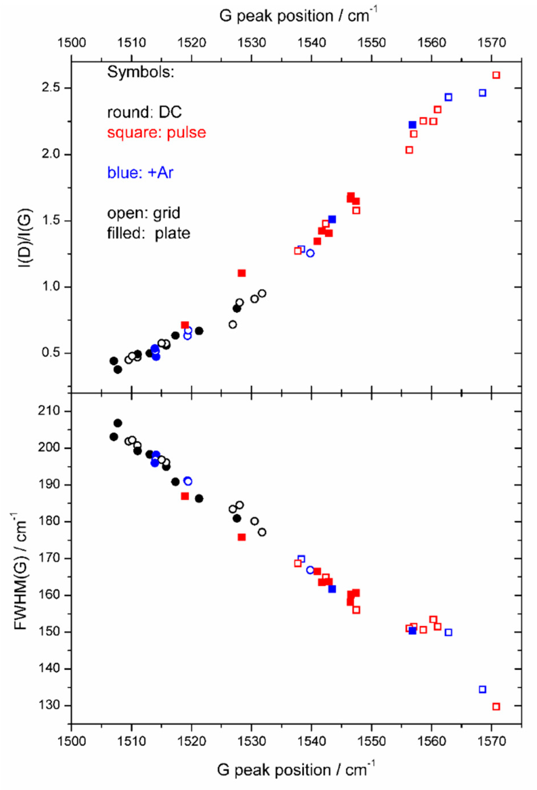
Figure 1. The correlation of the ratio I(D)/I(G) and of the full width at half maximum of the G peak (FWHM(G)) with the G peak position, as derived from the Raman spectra.
Coatings 10 00360 g001
Figure 2. G peak position, FWHM(G) and ratio I(D)/I(G) as functions of high voltage for films prepared by a DC and a pulsed voltage, with the plate holder. The pressure (in Pa) during the film preparation is indicated by color as shown in the legend.
Coatings 10 00360 g002
Figure 3. Influence of the addition of argon in the plasma gas. The symbols represent the same as in Figure 1; i.e., round: DC, square: pulse; blue color: Ar addition; open: grid-type holder, filled: plate holder. (a) G peak position with Ar flow; (b) peak width of the G peak (FWHM(G)) with Ar flow; (c) I(D)/I(G) value with Ar flow.
Coatings 10 00360 g003aCoatings 10 00360 g003b
Figure 4. Hardness of all films as a function of the hydrogen content.
Coatings 10 00360 g004
Figure 5. Friction coefficient of all films as function of hydrogen content.
Coatings 10 00360 g005