Article

An Investigation on Structural and Optical Properties of Zn1−xMgxS Thin Films Deposited by RF Magnetron Co-Sputtering Technique

1
Institute of Fuel Research and Development (IFRD), Bangladesh Council of Scientific and Industrial Research (BCSIR), Dhaka 1205, Bangladesh
2
Department of Physics, Jahangirnagar University, Dhaka 1342, Bangladesh
3
Institute of Sustainable Energy (ISE), Universiti Tenaga Nasional, Selangor Kajang 43000, Malaysia
4
Department of Electrical and Electronic Engineering, College of Engineering (COE), Universiti Tenaga Nasional (The Energy University), Selangor Kajang 43000, Malaysia
5
Solar Energy Research Institute, Universiti Kebangsaan Malaysia, Selangor Bangi 43600, Malaysia
*
Authors to whom correspondence should be addressed.
Coatings 2020, 10(8), 766; https://doi.org/10.3390/coatings10080766
Submission received: 4 June 2020 / Revised: 13 July 2020 / Accepted: 15 July 2020 / Published: 6 August 2020

Abstract

:
In this paper, Zn1−xMgxS thin films were co-sputtered on glass substrates using ZnS and MgS binary target materials under various applied RF power. The compositional ratio of Zn1−xMgxS films was varied by changing the RF power at an elevated temperature of 200 °C. The structural and optical properties were studied in detail. The structural analysis shows that the co-sputtered Zn1−xMgxS thin films have a cubic phase with preferred orientation along the (111) plane. The lattice constant and ionicity suggest the presence of a zincblende structure in Zn1−xMgxS thin films. Zn1−xMgxS thin films have transmittance over 76%. The extrapolation of optical characteristics indicates that direct bandgaps, ranging from 4.39 to 3.25 eV, have been achieved for the grown Zn1−xMgxS films, which are desirable for buffer or window layers of thin film photovoltaics.

1. Introduction

ZnS and MgS-based devices have shown promising results in optoelectronic applications. Further modifications of these materials can make their range of properties broader in the respective applications. In fabricating semiconductor devices such as thin film solar cells, there is a need for an n-type buffer layer material to form a metallurgical and electrical junction with the p-type absorber layer. The Zn1−xMgxS thin film has drawn significant interest as a buffer layer in thin film photovoltaics in recent years. II-VI compounds, such as CdS [1,2,3,4], ZnS [5,6,7], CdZnS [8,9,10,11,12], etc., are commonly used as buffer layers. The bandgap of these films varies from 2.45 to 3.25 eV. For ultraviolet (UV) optoelectronic devices such as UV detectors, sensors, and sources (UV-LEDs, UV-lasers), it is necessary to have much wider bandgap materials. Wide bandgap II-VI compounds are promising for short wavelength optoelectronic applications, i.e., from the green to the ultraviolet spectral region [13]. Usually, group III-V-based materials are used in UV detectors, however, the synthesis as well as usage are quite troublesome [14].
On the other hand, Zn-chalcogenide, e.g., ZnS, and alkaline-earth chalcogenide, e.g., MgS, are promising materials for optoelectronic devices [15]. MgS can be crystallized in rocksalt (RS), zincblende (ZB), and wurtzite structures. Naturally, MgS favors the rocksalt structure. Based on the theoretical calculation by Kalpana et al. [16], both rocksalt and zincblende structures are indirect-gap materials. Okuyama et al. [17] determined the bandgap energy of zincblende MgS at room temperature to be 4.45 ± 0.2 eV. Haque et al. [6] found that ZnS is a direct bandgap material with a bandgap energy of 3.24 ± 0.05 eV at room temperature. Therefore, it can be summarized that bandgap engineering is possible by controlling the synthesis processes of II–VI group ternary alloy ZnMgS. This ternary alloy has successfully been synthesized by various physical techniques, such as molecular beam epitaxy [18,19], metalorganic vapor phase epitaxial growth [20], solid solution [15,21,22], sputtering [15], and chemical approach [23,24,25].
This work reports the deposition of Zn1−xMgxS thin films by RF magnetron co-sputtering from individual ZnS and MgS targets for the first time. The structural and optical characterizations of the ZnMgS layer are discussed in detail, based on the findings from the experiments conducted throughout this study.

2. Materials and Methods

2.1. Deposition of Thin Films

A top-up magnetron sputtering system, manufactured by Kurt J. Lesker Company with Model PRO Line PVD75, was used for the deposition of ZnMgS thin films. Figure 1 shows the schematic diagram of the system. Two sputter targets of MgS (Super Conductor Materials, Inc. with Purity 99.99%) and ZnS (Angstrom Sciences, Inc. with Purity 99.99%), each with a diameter of 50.8 mm, were placed below the substrate. The targets were respectively connected to RF1 (maximum 300 W, frequency 13.56 MHz) and RF2 (maximum 300 W, frequency 12.56 MHz) power sources. Borosilicate glass slides (BSG) of size 30 × 30 mm2 and thickness of 2 mm were used as substrate and placed about 80.0 mm above the targets. Inside the chamber, the substrate holder was placed onto a rotating stage capable of rotating up to 20 rpm. The rotating state was connected to a resistive heater capable of reaching up to 300 °C. For deposition, the base pressure inside the chamber was maintained below 0.66 mPa.
Deposition rates were assessed by separate deposition of MgS and ZnS on to cleaned BSG substrates at an operating pressure of 0.40 Pa for 30 min under different applied sputtering power at 200 °C. The substrate was cleaned sequentially by methanol-acetone-methanol solutions in the ultrasonic bath followed by DI water for 10 min in each solution. The glass substrates were then dried using a dry air blower. Ketone tape strips were used to mask one side of the substrate prior to each deposition of MgS and ZnS.
After optimization of the deposition rate and composition of individually deposited MgS and ZnS films, the Zn1−xMgxS precursor films were deposited onto BSG substrates by co-sputtering of MgS and ZnS targets at a working pressure of 0.40 Pa with an argon flow rate of 15 sccm. During the deposition, the substrate holder was set to 20 rpm and heated at 200 °C. After deposition, the ZnMgS films were annealed at 550, 450, and 375 °C for 30 min in N2 atmosphere at 3.33 Pa pressure in a Rapid Thermal Annealing chamber, manufactured by Advance Riko with Model MILA-5000-P-N, to ensure better crystalline property. Since X-ray diffraction (XRD) patterns of annealed samples did not show any significant changes with respect to the as-deposited samples, therefore, all characterizations were performed for the as-deposited films only.

2.2. Characterization of Thin Films

The thickness of the films was measured by a surface profilometer (DektaXT-A; Bruker Corporation, Swedesboro, NJ, USA). The composition of the films on BSG substrates was investigated by energy dispersive analysis of X-ray (TEAM EDS; EDAX, Mahwah, NJ, USA). The crystalline phase of the films was studied with an X-ray diffractometer (XRD) (EMMA; GBC Scientific Equipment, Braeside, Australia) using Cu Kα radiation (λ = 0.15406 nm) operated at 35.5 kV and 28 mA. The optical properties of the films were characterized by an ultraviolet-visible-near-infrared (UV-Vis-NIR) spectrometer (UH-4150; Hitachi High Technologies Corporation, Tokyo, Japan) with a wavelength range from 300 to 1100 nm. The surface topology as well as roughness of the films were determined by atomic force microscope (AFM) (C3000, FlexAFM; Nanosurf AG, Liestal, Switzerland). Photoluminescence was performed by a photoluminescence (PL) unit (Mini-Pl/Raman; Photon Systems, Covina, CA, USA) using 248.6 nm laser excitation at 300 K. All of the characterizations were performed at room temperature.

3. Results and Discussion

Prior to the deposition of Zn1−xMgxS films by co-sputtering, the deposition characteristics, such as sputtering deposition rate on glass substrates of the target materials, were assessed upon their individual sputtering.
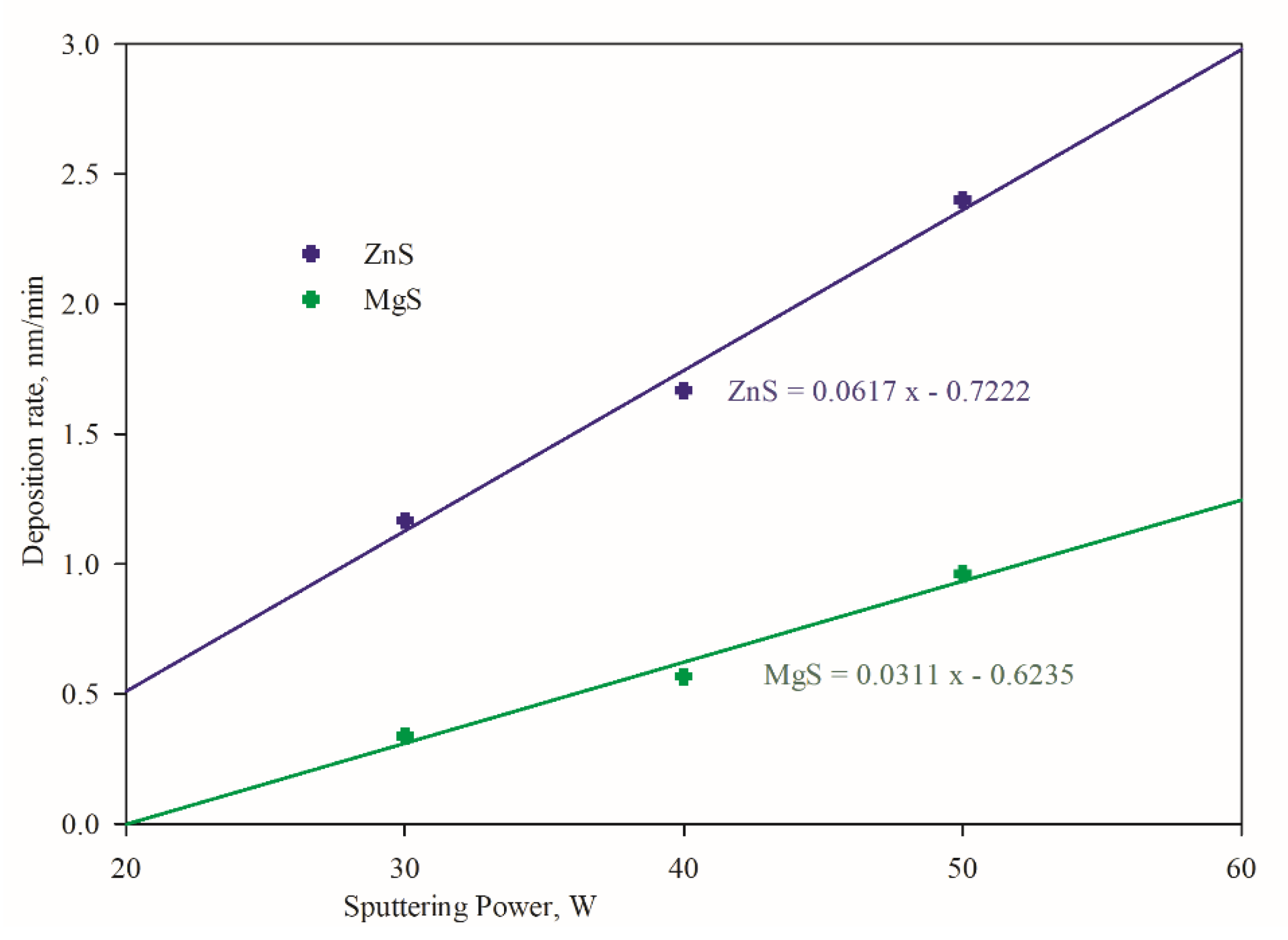
To assess the film growth rate, deposition was carried out at various sputtering power for each individual target, as shown in Figure 2. It was found that the film growth from ZnS target yielded higher than the MgS target. MgS target led to deposition rate at 0.34 nm/min at 30 W, which linearly increased to 0.96 nm/min at 50 W. Target power and deposition rate were related by a slope of 0.0311 and a linear correlation coefficient (R) of 0.976. The ZnS target achieved 1.17 nm/min at 30 W, which linearly increased to 2.40 nm/min at 50 W, with a slope of 0.0617 and R of 0.988. The linear dependence of deposition rate on the sputtering cathode or target power is favorable to allow the precise growth/deposition engineering of Zn1−xMgxS thin films.

3.1. Compositional Variations

The atomic percentage of the corresponding materials of individually deposited ZnS and MgS films were calculated from EDS. Table 1 shows the average atomic percentage of the deposited thin films of ZnS and MgS.
The observed deposition rates and atomic percentages are subsequently used in the deposition of Zn1−xMgxS films (x = 0.1 to 0.9). These “x” values are obtained by decreasing the RF power of the MgS target from 40 W to 20.98 W and increasing the RF power of the ZnS target from 20 to 70.51 W, as indicated in Table 2.
The elemental compositions of Zn1−xMgxS thin films are assessed by energy dispersive spectroscopy (EDS) measurements. The EDS analysis of nine Zn1−xMgxS thin films deposited by changing the RF power of MgS and ZnS is shown in the table. The non-monotonic behavior of Zn and Mg concentration in the deposited film for x = 0.51 may be due to the composition of the sputter targets used. During sputter deposition process, sputtered atoms are made up of atom species that were located on or near the surface of the sputter targets. Thus, the sputtering yield of the various atomic species is not necessarily a reflection of the bulk composition of the sputter targets. Thus, it is possible that less Zn or more Mg was present on the surface of sputter targets during the deposition for x = 0.51. This is then reflected in the non-monotonic behavior of the contents of Zn and Mg at x = 0.57 to 0.41.

3.2. Structural Properties

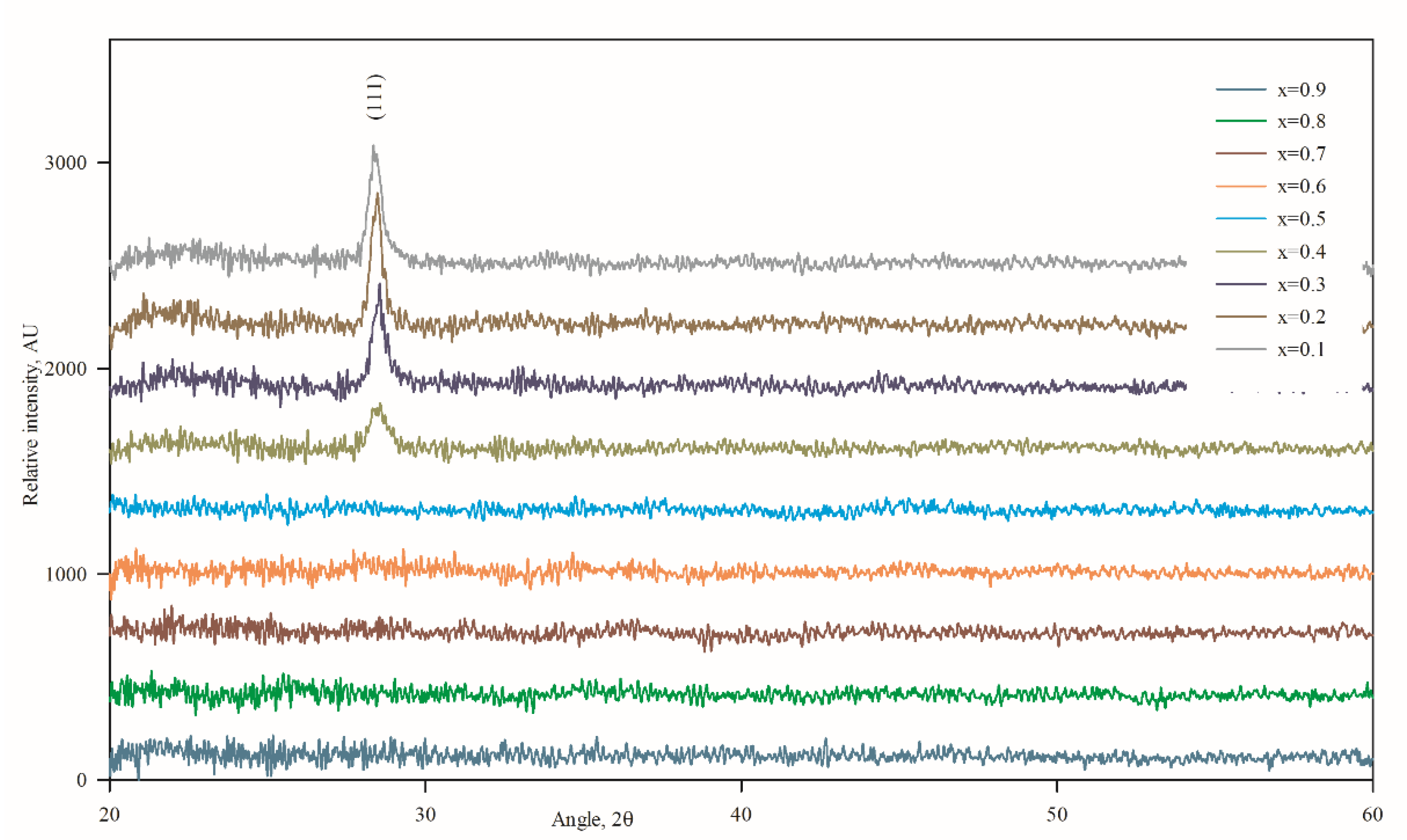
As shown in Figure 3, there was only one prominent peak found at 2θ = 28.48° in the XRD patterns of the sputtered thin films for “x” values ranging from 0.1 to 0.4, which indicates that the films are single crystalline with a preferential orientation, and the planes are parallel to the substrate surface. Generally, ZnS exhibits polymorphism of the zincblende (ZB) structure of the cubic phase and wurtzite structure of the hexagonal phase [26]. In our case, the (111) planes of the cubic phase showed a peak at about 28.55°, as supported by JCPDS 05-0566. The peak shift occurs because of Mg incorporation in the ZB structure, and the peak intensity decreases gradually as the concentration of Mg increases. The highest peak height observed for x = 0.2 and the corresponding calculated crystallite size from Debye–Scherrer’s [27] formula for Zn0.8Mg0.2S found the highest value of 22.29 nm. Based on Debye–Scherrer’s formula, one can calculate the crystallite size which is perpendicular to the surface. On the other hand, AFM measurements reveal the lateral size of the crystallite, which also can be correlated with the underlying grain growth mechanism. In this study, it was found that Zn0.8Mg0.2S film simultaneously possesses the highest crystallite size as well as highest lateral grain size, as evident from Table 3.
Zincblende or wurtzite structures are more favorable for group-IIB elements like ZnS, whereas rocksalt structure is more favorable for group-IIA elements like MgS [28,29]. The lattice parameter of ZnS (ZB) is about 0.541 nm [30,31,32], MgS (ZB) is 0.566 nm, and MgS (RS) is about 0.518 nm [33,34]. In our Zn1−xMgxS structure, for x = 0.1 to 0.4, the Mg is incorporated into the ZnS (ZB) structure by replacing Zn and found the lattice parameter around that of ZnS (ZB), as shown in Figure 4. On the other hand, the formation of Zn1−xMgxS is a common-anion type super-lattice, which is thermodynamically unstable in epitaxial growth [35]. This may be one of the reasons for the amorphous state for Mg-rich films. In the growth process of Zn1−xMgxS films, the ZnS target contributes the sulfur component, as found from the EDS (Table 1) data on individually deposited films. It is, therefore, reasonable to state that with Zn1−xMgxS films of x > 0.4, there is insufficient sulfur content to form a stoichiometric crystal structure. Post-deposition sulfurization will, therefore, be needed for thin films with x > 0.4 for better crystalline property.
The lattice constant of the deposited film, as shown by the blue line in Figure 4, gradually increases with the increase in Mg concentration. In tetrahedral coordination, a decrease in the attractive potential between the bonding electrons and atomic cores of Mg over Zn causes an increase in bond length [36]. Phillips [37] discussed the fraction of ionic character in a fourfold coordinated binary system. The ionicity variation with the reported Eh and C values [37] is calculated using the following equation:
f i = C 2 E h 2 + C 2
where fi is the ionicity, C is the anti-symmetric ionic energy gap, and Eh is the symmetric covalent energy gap. The calculated ionicity, as shown by the orange line in Figure 4, also gradually increases from 0.641 to 0.689, as the Mg incorporation (concentration) increases. This value strongly suggests the presence of a ZB phase in Zn1−xMgxS films.
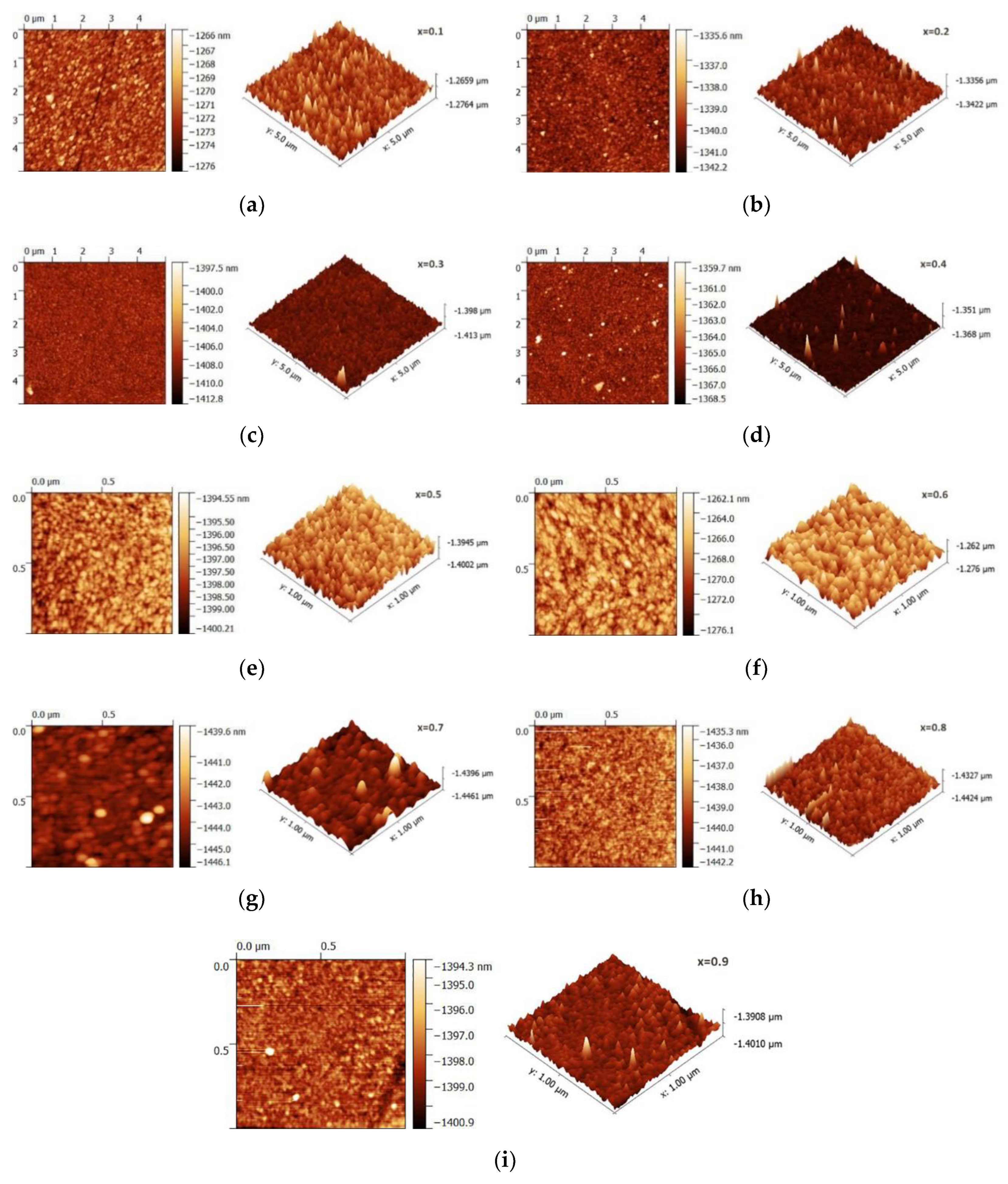
From AFM analysis, the lowest surface roughness and highest grain size were observed in x = 0.2 samples, with the corresponding roughness and grain size values of 0.414 and 186 nm, as shown in Figure 5. The roughness and grain size values for all the deposited samples are shown in Table 3.

3.3. Optical Properties

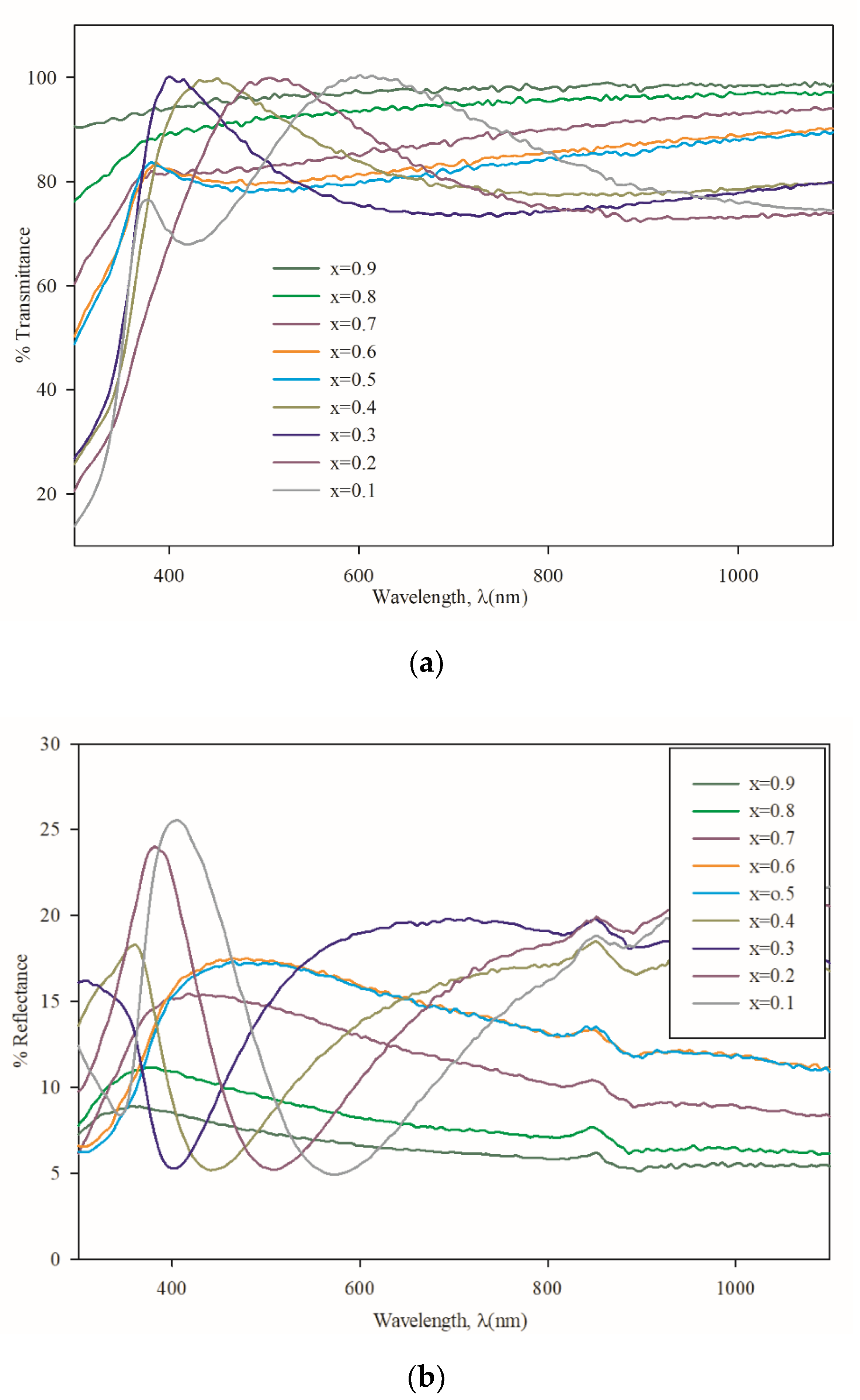
Figure 6a shows the variation of transmittance and Figure 6b shows the variation of reflectance with respect to wavelength for all the thin film samples. It is found that the average transmittance above 400 nm increases from 76% to 98% with increasing Mg concentration. Confirming the presence of good crystallinity from XRD data, the “x” value from 0.1 to 0.4 also showed a sharp fall at the band edges, which is good for optoelectronic devices, especially for solar cell buffer layers.
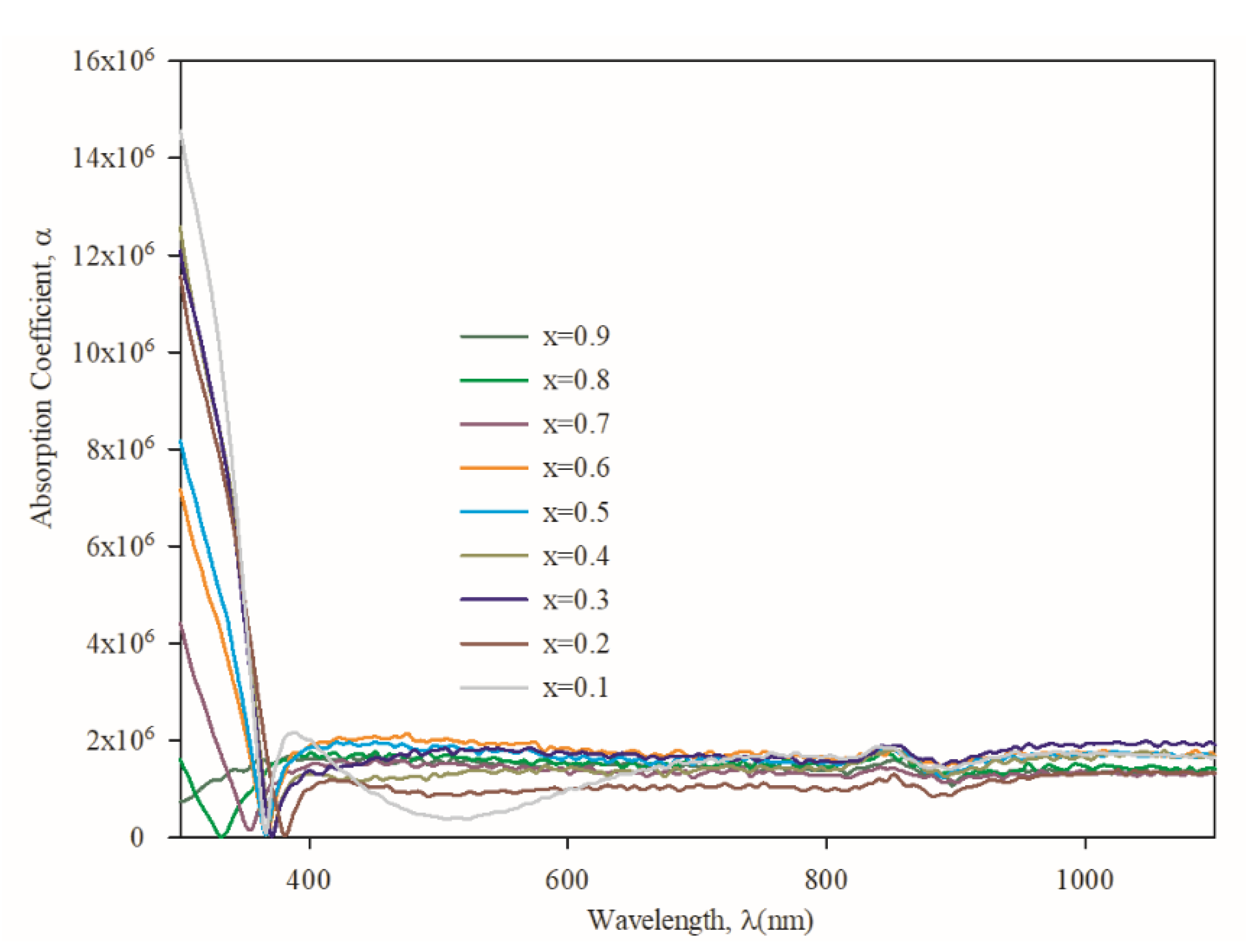
The optical properties of the Zn1−xMgxS films are examined by UV-visible absorption spectroscopy, as shown in Figure 7. The optical absorption coefficient (α) is calculated using the equation [38]:
α = 1 t ln ( 1 R ) 2 T
where t is the thickness of the films, R is reflectance, and T is transmittance. A sudden decrease, from 300 to 380 nm, is observed in the absorption spectra, which indicates the presence of an optical bandgap in the thin film, confirming the behavior as a semiconductor. The absorption edge in the spectra is shifted towards the lower wavelength as the Mg content increases in the Zn1−xMgxS thin films.
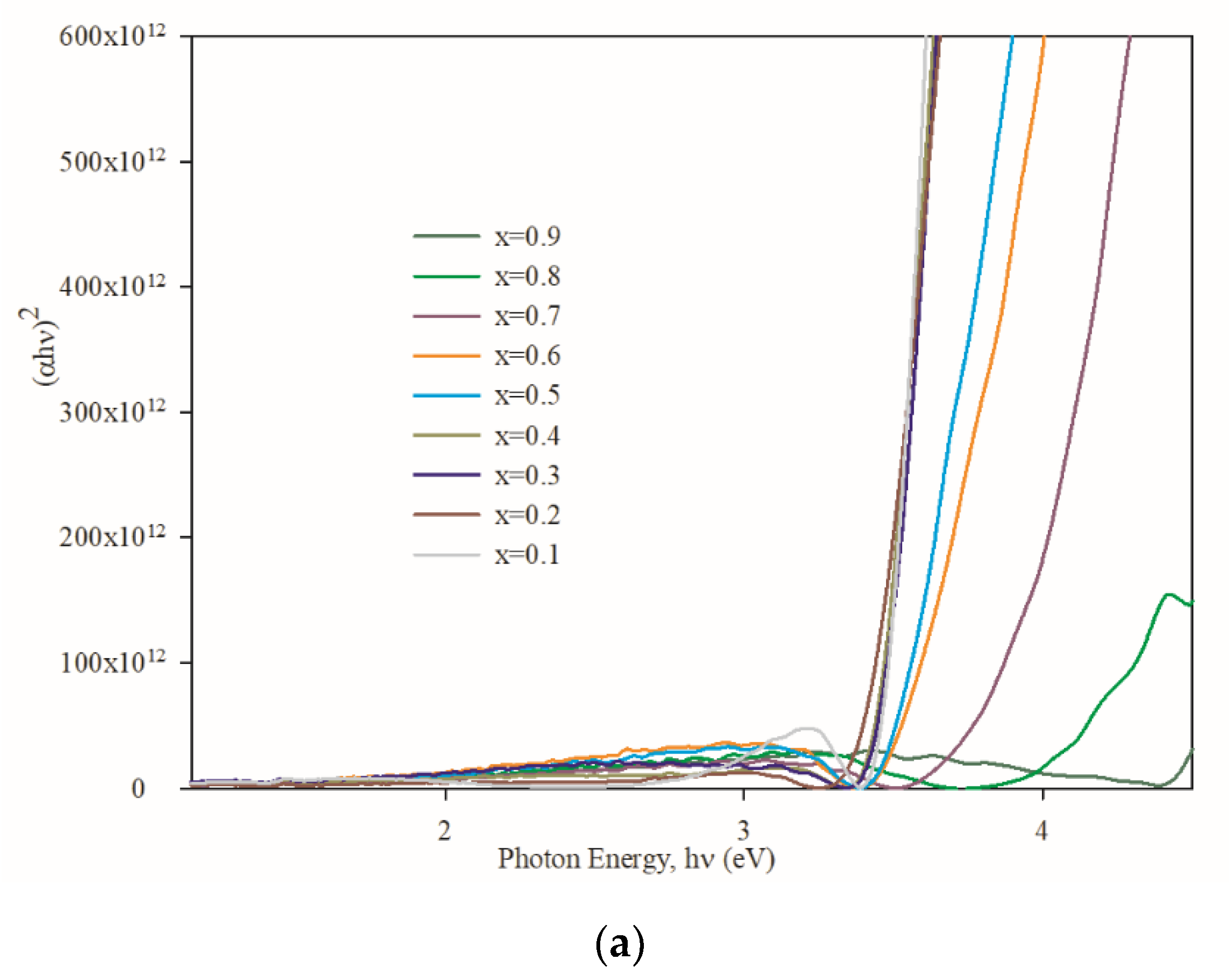
Plotting (αhν)2 with respect to incident photon energy allows the calculation of a semiconductor direct optical energy bandgap (Eg) using the following Tauc relation [39]:
(αhν)2 = (hν − Eg)
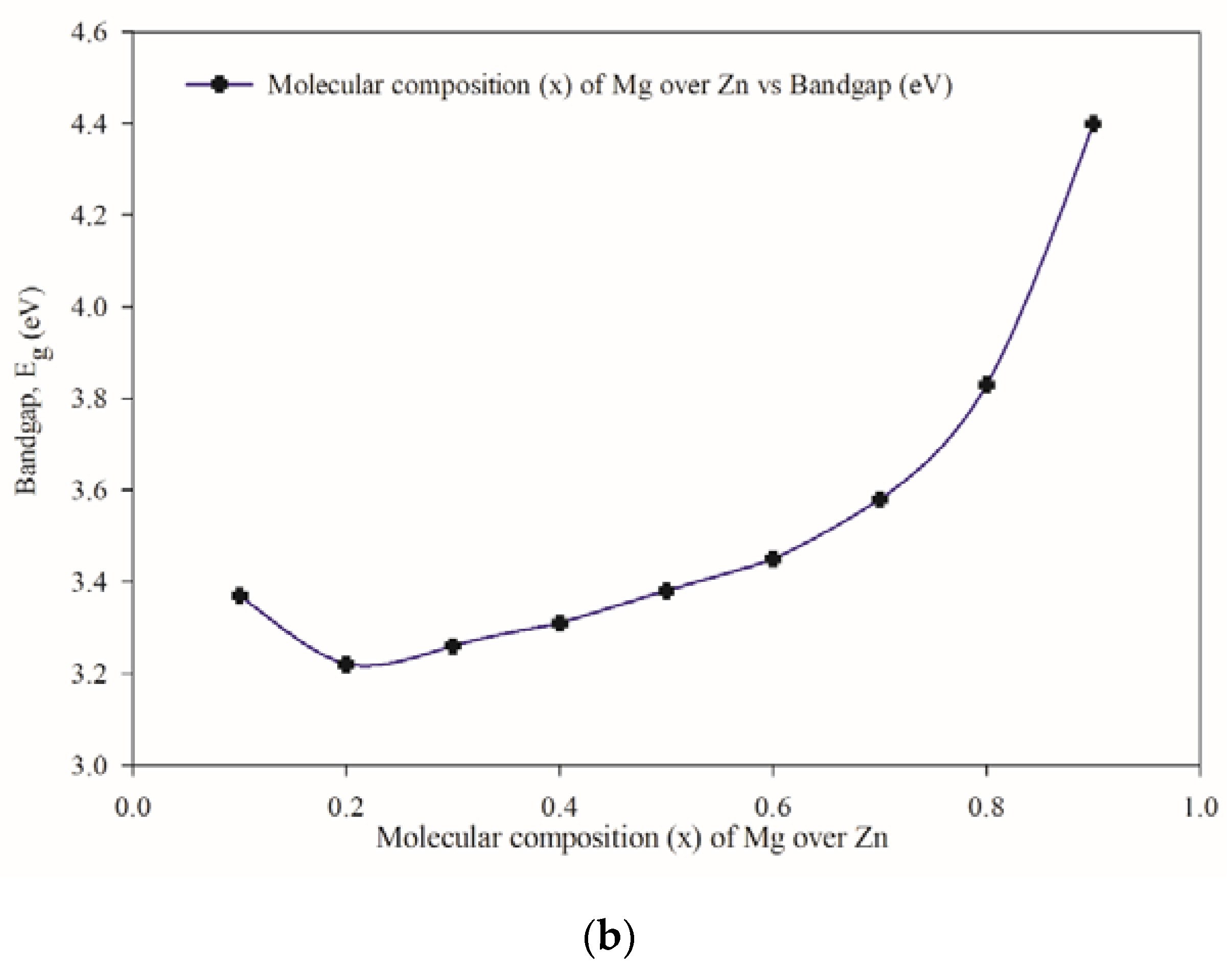
The linear nature of the plots at the absorption edge confirms that Zn1−xMgxS is a semiconductor with a direct energy bandgap. The optical energy band gap is calculated from Figure 8a by extrapolating the linear portion of the curve to (αhν)2 = 0 for each composition and found to be in the range of 4.39 and 3.25 eV (Figure 8b). The lowest bandgap is found for x = 0.2 composition, whereas the highest value is found for that of x = 0.8. The decrease in energy bandgap with decreasing Mg concentration is to be expected.
The anomaly observed between x = 0.2 and x = 0.5 may be that Zn1−xMgxS alloys do not obey Vegard’s Law. In semiconductor physics, Vegard’s Law is often used to approximate the lattice parameter, and subsequently, the bandgap (Eg) for semiconducting alloys. For semiconducting alloys that obey Vegard’s Law, a linear relationship between the bandgap and composition can be established. However, most semiconducting alloys do not obey Vegard’s Law, therefore, a linear relationship between the bandgap and composition will not be observed. As evident in the plot for lattice parameter in Figure 4, the change in lattice parameter for the Zn1−xMgxS samples is not linear. Thus, Zn1−xMgxS belong in the latter group of semiconducting materials that do not obey Vegard’s Law. Hence, the optical parameters for Zn1−xMgxS will not vary in a linear manner with the change in composition. Okuyama et al. [17] reported similar observations for Zn1−xMgxS ternary alloys, while Asano et al. [40] showed them for Zn1−xMgxTe alloys.
The photoluminescence (PL) spectra, as shown in Figure 9, show a little peak shift to lower energy, compared to those of MgS [41], which indicates the continuous increase in Mg incorporation in ZnS thin films. Two electronic transition bands have been observed, one at 450 nm for all the samples and the other at around 375 nm, that increase alongside the Mg concentration. According to O′Neil et al. [42] and Spanhel et al. [43], the excitonic emission is located near the absorption edge of the particles. From Figure 7, the absorption edges of the films were in between 300 to 380 nm, which comply with PL data in Figure 9. Kurse et al. [44] show similar PL spectra of ZnSe/MgS superlattices at room temperature. It is, therefore, quite reasonable to believe that the incorporation of Mg in ZnS films, the PL peaks as well as the bandgap increases with Mg concentration. The emission band at 450 nm is due to the presence of ZnS [45] in binary form in all Zn1−xMgxS films. Since MgS is an indirect bandgap semiconductor, there has not been any PL peak recorded below 300 nm. The higher double PL peaks for the case of x = 0.1 were obtained. This may be due to the individual formation of ZnS and MgS instead of the ternary alloy Zn1−xMgxS.

4. Conclusions

Zn1−xMgxS thin films with varying compositional ratios of Zn and Mg were successfully deposited by optimizing the deposition power during the co-sputtering process. The XRD patterns indicate preferential orientation along the (111) plane of the cubic phase, with a peak at around 28.55°. The lattice constant and ionicity gradually increase with increasing Mg incorporation, which suggests the presence of a zincblende (ZB) phase in the Zn1−xMgxS films. The lowest surface roughness, highest crystallinity, and grain size are observed for Zn0.8Mg0.2S. Bandgap values also match well with photoluminescence spectra. Consequently, a wider direct bandgap within the range of 4.39 and 3.25 eV as well as transmittance of over 76% indicate that these films are suitable candidates for application in optoelectronic devices.

Author Contributions

Conceptualization, methodology and investigation, N.A., M.S.B., M.R., F.A. and A.G.; funding acquisition and resources Y.Y., S.F.A. and N.A.; formal analysis and data curation, P.C., M.S.B., F.A. and M.A. All authors have read and agreed to the published version of the manuscript.

Funding

This study is supported by Bangabandhu Science and Technology Fellowship Trust under the Ministry of Science and Technology, Peoples Republic of Bangladesh. This work was mainly executed at the facilities of the Bangladesh Council of Scientific and Industrial Research (BCSIR). The characterization and analyses of the samples prepared in this study was supported by Universiti Tenaga Nasional of Malaysia (UNITEN) under the Malaysian Ministry of Education grant with code FRGS/1/2018/TK05/UNITEN/02/1. The publication of this work was also supported by UNITEN through its Internal Research Grant Opex (RJO10517919/iRMC/Publication).

Conflicts of Interest

The authors declare no conflict of interest exists with any parties. The funders had no role in the design of the study; in the collection, analyses, or interpretation of data; in the writing of the manuscript, or in the decision to publish the results.

References

  1. Islam, M.A.; Hossain, M.S.; Aliyu, M.M.; Husna, J.; Huda, Q.U.; Karinm, M.R.; Sopian, K.B.; Amin, N. Growth of Wide Bandgap CdS Thin Films as Window Layers of Ultra Thin CdTe Solar Cells. In Proceedings of the 22nd International Photovoltaic Science and Engineering Conference, Hangzhou, China, 5–9 November 2012; pp. 1–5. [Google Scholar]
  2. Matin, R.; Bashar, M.S.; Sultana, M.; Ahmed, A.N.; Gafur, A. Annealing effects on the structural, optical and electrical properties of chemically deposited CdS thin films using NH4Cl complexing agent. Int. J. Nanoelectron. Mater. 2018, 11, 221–232. [Google Scholar]
  3. Matin, M.A.; Amin, N.; Zaharim, A.; Sopian, K. Ultra thin high efficiency CdS/CdTe thin film solar cells from numerical analysis. In Proceedings of the 8th WSEAS International Conference on NON-Linear Analysis, Non-Linear Systems and Chaos, La Laguna, Canary Islands, Spain, 1–3 July 2009; pp. 338–344. [Google Scholar]
  4. Rupom, R.H.; Matin, R.; Bashar, M.S.; Sultana, M.; Rahaman, M.; Gafur, M.A.; Hakim, M.; Hossain, M.K.; Bhuiyan, M.M.R.; Ahmed, F. Fabrication and Characterization of Cadmium Sulfide (CdS) Buffer Layer Thin Film by Using Chemical Bath Deposition Method for Solar Cell. Am. Int. J. Res. Sci. 2016, 14, 10–15. [Google Scholar]
  5. Majeed, S.; Siraj, K.; Naseem, S.; Khan, M.F.; Irshad, M.; Faiz, H.; Mahmood, A. Structural and optical properties of gold-incorporated diamond-like carbon thin films deposited by RF magnetron sputtering. Mater. Res. Express 2017, 4, 076403. [Google Scholar] [CrossRef]
  6. Haque, F.; Rahman, K.S.; Islam, M.A.; Rashid, M.J.; Akhtaruzzaman, M.; Alam, M.M.; Alothman, Z.A.; Sopian, K.B.; Amin, N. Growth optimization of ZnS thin films by RF magnetron sputtering as prospective buffer layer in thin film solar cells. Chalcogenide Lett. 2014, 11, 189–197. [Google Scholar]
  7. Islam, M.A.; Hossain, M.S.; Aliyu, M.M.; Sulaiman, Y.; Karim, M.R.; Sopian, K.; Amin, N. Comparative study of ZnS thin films grown by chemical bath deposition and magnetron sputtering. In Proceedings of the 2012 7th International Conference on Electrical and Computer Engineering, Dhaka, Bangladesh, 20–22 December 2012; pp. 86–89. [Google Scholar]
  8. Hossain, M.; Rahman, K.; Islam, M.; Akhtaruzzaman, M.; Misran, H.; Alghoul, M.; Amin, N. Growth optimization of ZnxCd1-xS films on ITO and FTO coated glass for alternative buffer application in CdTe thin film solar cells. Opt. Mater. 2018, 86, 270–277. [Google Scholar] [CrossRef]
  9. Hossain, S.; Kabir, H.; Rahman, M.M.; Hasan, K.; Bashar, M.S.; Rahman, M.; Gafur, A.; Islam, S.; Amri, A.; Jiang, Z.-T.; et al. Understanding the shrinkage of optical absorption edges of nanostructured Cd-Zn sulphide films for photothermal applications. Appl. Surf. Sci. 2017, 392, 854–862. [Google Scholar] [CrossRef]
  10. Hossain, M.S.; Rahman, K.S.; Karim, M.R.; Aijaz, M.O.; Dar, M.A.; Shar, M.A.; Misran, H.; Amin, N. Impact of CdTe thin film thickness in ZnxCd1−xS/CdTe solar cell by RF sputtering. Sol. Energy 2019, 180, 559–566. [Google Scholar] [CrossRef]
  11. Akh, S.; Matin, R.; Bashar, M.S.; Kowsar, A.; Rahaman, M.; Mahmood, Z.H.; Akhanda, S. Experimental Study on Structural, Optical and Electrical Properties of Chemical Bath Deposited CdZnS Thin Films. J. Fundam. Renew. Energy Appl. 2017, 7. [Google Scholar] [CrossRef] [Green Version]
  12. Inoue, R.; Kitagawa, M.; Nishigaki, T.; Ichino, K.; Kobayashi, H.; Ohishi, M.; Saito, H. Optical band gap of ZnxMg1−xS thin films with composition x between 0.14 and 1. J. Cryst. Growth 1998, 184, 1076–1080. [Google Scholar] [CrossRef]
  13. Khan, I.; Ahmad, I.; Aliabad, H.A.R.; Maqbool, W. Effect of phase transition on the optoelectronic properties of Zn1−xMgxS. J. Appl. Phys. 2012, 112, 73104. [Google Scholar] [CrossRef]
  14. Kimijima, H.; Kitagawa, M.; Inoue, R.; Shiraishi, N.; Hoashi, M.; Ichino, K.; Kobayashi, H. Deposition and characterization of ZnxMg1−xS thin films on amorphous substrates. Appl. Surf. Sci. 1997, 113, 432–435. [Google Scholar] [CrossRef]
  15. Kalpana, G.; Palanivel, B.; Thomas, R.M.; Rajagopalan, M. Electronic and structural properties of MgS and MgSe. Phys. B Condens. Matter 1996, 222, 223–228. [Google Scholar] [CrossRef]
  16. Okuyama, H.; Kishita, Y.; Ishibashi, A. Quaternary alloy Zn1−xMgxSySe1−y. Phys. Rev. B 1998, 57, 2257–2263. [Google Scholar] [CrossRef]
  17. Bradford, C.; Moug, R.; Curran, A.; Thuau, D.; Warburton, R.J.; Prior, K. Growth and Characterization of ZnMgS and ZnMgS/ZnSe Quantum Wells grown on GaAs (100) by Using MBE. J. Korean Phys. Soc. 2008, 53, 3000–3003. [Google Scholar] [CrossRef]
  18. Sou, I.K.; Wu, M.C.W.; Sun, T.; Wong, K.S.; Wong, G.K.L. MBE-Grown ZnMgS ultra-violet photodetectors. J. Electron. Mater. 2001, 30, 673–676. [Google Scholar] [CrossRef]
  19. Rodriguez, A.; Shattuck, J.; Zhang, X.; Li, P.; Parent, D.; Ayers, J.; Jain, F. Photo-Assisted MOVPE Growth of ZnMgS on (100) Si. MRS Proc. 2001, 692, 625–630. [Google Scholar] [CrossRef] [Green Version]
  20. Brightwell, J.W.; Ray, B.; White, S. Phase structure of Zn1-xMgxS prepared by reaction of mixed chlorides with H2S. J. Mater. Sci. Lett. 1984, 3, 951–954. [Google Scholar] [CrossRef]
  21. Amah, A.N. Synthesis and optical characterization of ZnMgS:Eu nanoparticles. Turk. J. Phys. 2013, 37, 289–295. [Google Scholar] [CrossRef]
  22. Dive, A.; Gattu, K.; Huse, N.; Upadhayay, D.R.; Phase, D.; Sharma, R.B. Single step chemical growth of ZnMgS nanorod thin film and its DFT study. Mater. Sci. Eng. B 2018, 228, 91–95. [Google Scholar] [CrossRef]
  23. Dong, L.M.; Li, M.J.; Liu, X.D.; Wu, K.J.; Guo, Y.K. Study on structural and luminescence properties of ZnS: Mg2+ quantum dots synthesized with aqueous method. J. Ovonic Res. 2016, 12, 155–161. [Google Scholar]
  24. Shahid, M.Y.; Asghar, M.; Zafar, M.; Ilyas, S.Z.; Arbi, H.M. Role of magnesium in ZnS structure: Experimental and theoretical investigation. AIP Adv. 2016, 6, 025019. [Google Scholar] [CrossRef] [Green Version]
  25. Shao, L.-X.; Chang, K.-H.; Hwang, H.-L. Zinc sulfide thin films deposited by RF reactive sputtering for photovoltaic applications. Appl. Surf. Sci. 2003, 212, 305–310. [Google Scholar] [CrossRef]
  26. Warren, B.E.; Muldawer, L. X-Ray Diffraction. Phys. Today 1970, 23, 53. [Google Scholar] [CrossRef]
  27. Morinaga, Y.; Okuyama, H.; Akimoto, K. Photopumped Blue Lasers with ZnSSe-ZnMgSSe Double Heterostructure and Attempt at Doping in ZnMgSSe. Jpn. J. Appl. Phys. 1993, 32, 678–680. [Google Scholar] [CrossRef]
  28. Guo, Y.-D.; Yang, Z.-J.; Gao, Q.-H.; Dai, W. Structural and elastic properties of MgS via first-principle calculations. Phys. B Condens. Matter 2008, 403, 2367–2371. [Google Scholar] [CrossRef]
  29. Hotje, U.; Rose, C.; Binnewies, M. Lattice constants and molar volume in the system ZnS, ZnSe, CdS, CdSe. Solid State Sci. 2003, 5, 1259–1262. [Google Scholar] [CrossRef]
  30. Lucero, M.J.; Henderson, T.M.; E Scuseria, G. Improved semiconductor lattice parameters and band gaps from a middle-range screened hybrid exchange functional. J. Phys. Condens. Matter 2012, 24, 145504. [Google Scholar] [CrossRef] [PubMed] [Green Version]
  31. Qadri, S.; Skelton, E.F.; Hsu, D.; Dinsmore, A.D.; Yang, J.; Gray, H.F.; Ratna, B.R. Size-induced transition-temperature reduction in nanoparticles of ZnS. Phys. Rev. B 1999, 60, 9191–9193. [Google Scholar] [CrossRef]
  32. Drief, F.; Tadjer, A.; Mesri, D.; Aourag, H. First principles study of structural, electronic, elastic and optical properties of MgS, MgSe and MgTe. Catal. Today 2004, 89, 343–355. [Google Scholar] [CrossRef]
  33. Yuan, P.F.; Ding, Z. Ab initio calculation of elastic properties of rock-salt and zinc-blend MgS under pressure. Phys. B Condens. Matter 2008, 403, 1996–1999. [Google Scholar] [CrossRef]
  34. Lee, S.G.; Chang, K.J. First-principles study of the structural properties of MgS-, MgSe-, ZnS-, and ZnSe-based superlattices. Phys. Rev. B 1995, 52, 1918–1925. [Google Scholar] [CrossRef] [PubMed]
  35. Othman, Z.J.; Ayed, S.; Matoussi, A.; Khemakhem, H. Optical and Raman studies of Zn1-xMgxO ceramic pellets. Vib. Spectrosc. 2016, 85, 208–214. [Google Scholar] [CrossRef]
  36. Phillips, J.C.; Harrison, W.A. Bonds and Bands in Semiconductors. Phys. Today 1974, 27, 67. [Google Scholar] [CrossRef]
  37. Fewster, P.; Birkholz, M. Thin Film Analysis by X-ray Scattering; Wiley-VCH Verlag GmbH & Co. KGaA: Berlin, Germany, 2006. [Google Scholar]
  38. Pankove, J.I. Optical Processes in Semiconductors, 2nd ed.; Dover Publications, Inc.: Mineola, NY, USA, 2010. [Google Scholar]
  39. Asano, T.; Funato, K.; Nakamura, F.; Ishibashi, A. Epitaxial growth of ZnMgTe and double heterostructure of on GaAs substrate by metalorganic chemical vapor deposition. J. Cryst. Growth 1995, 156, 373–376. [Google Scholar] [CrossRef]
  40. Nashiki, H.; Suemune, I.; Kumano, H.; Suzuki, H.; Obinata, T.; Uesugi, K.; Nakahara, J. Excitonic luminescence up to room temperature in a ZnSe/MgS superlattice. Appl. Phys. Lett. 1997, 70, 2350–2352. [Google Scholar] [CrossRef]
  41. O’Neil, M.; Marohn, J.; McLendon, G. Dynamics of electron-hole pair recombination in semiconductor clusters. J. Phys. Chem. 1990, 94, 4356–4363. [Google Scholar] [CrossRef]
  42. Spanhel, L.; Haase, M.; Weller, H.; Henglein, A. Surface modification and stability of strong luminescing CdS particles. J. Am. Chem. Soc. 1987, 109, 5649–5655. [Google Scholar] [CrossRef]
  43. Kruse, C.; Alexe, G.; Klude, M.; Heinke, H.; Hommel, D. High Reflectivity p-Type Doped Distributed Bragg Reflectors Using ZnSe/MgS Superlattices. Phys. Status Solidi 2002, 229, 111–115. [Google Scholar] [CrossRef]
  44. Wang, Y.; Zhang, L.; Liang, C.; Wang, G.; Peng, X. Catalytic growth and photoluminescence properties of semiconductor single-crystal ZnS nanowires. Chem. Phys. Lett. 2002, 357, 314–318. [Google Scholar] [CrossRef]
  45. Camacho, G.J.O.; Marín, D.M.; Andrada, R.T.; Loscos, M.J.C.; Mariño, I.M.; Mariño, M.A.M. Efectos de la ingestión de cafeína sobre el rendimiento, la peroxidación lipídica y las vitaminas A, E y C, en sujetos sometidos a una prueba de esfuerzo máxima. Arch. Med. Deport 2002, 19, 371–375. [Google Scholar]
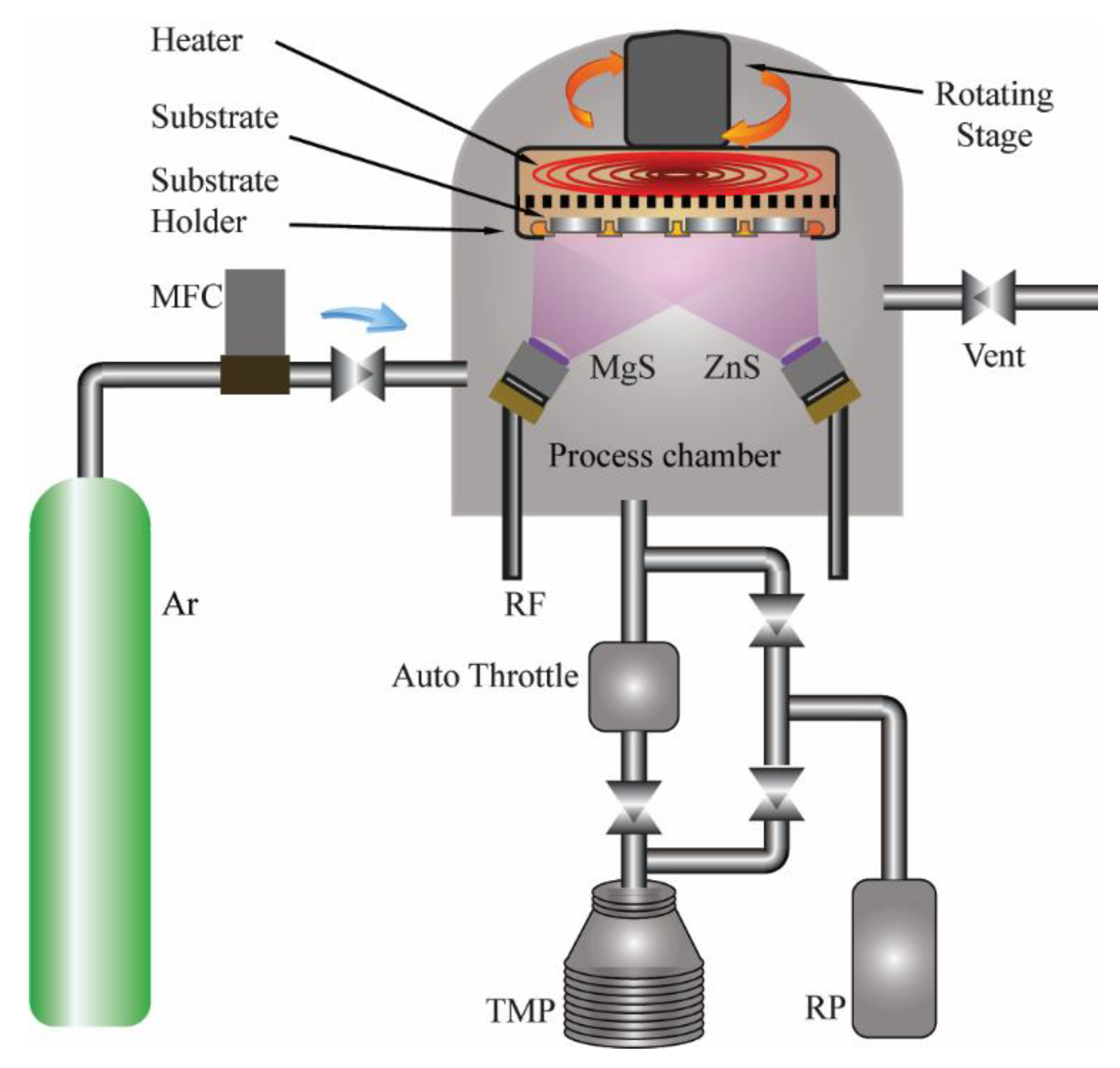
Figure 1. Schematic of the magnetron sputtering system used in ZnMgS thin film deposition.
Coatings 10 00766 g001
Figure 2. Effect of sputtering power on the film deposition rate.
Coatings 10 00766 g002
Figure 3. XRD patterns of Zn1−xMgxS thin films (0.1 ≤ x ≤ 0.9).
Coatings 10 00766 g003
Figure 4. Lattice constant and ionicity of Zn1−xMgxS thin films (0.1 ≤ x ≤ 0.4).
Coatings 10 00766 g004
Figure 5. AFM of Zn1−xMgxS thin films (0.1 ≤ x ≤ 0.9): (a) x = 0.1; (b) x = 0.2; (c) x = 0.3; (d) x = 0.4; (e) x = 0.5; (f) x = 0.6; (g) x = 0.7; (h) x = 0.8; (i) x = 0.9.
Coatings 10 00766 g005
Figure 6. (a) Transmittance vs. wavelength plots; (b) Reflectance vs. wavelength plots.
Coatings 10 00766 g006
Figure 7. Absorption coefficient of Zn1−xMgxS thin films (0.1 ≤ x ≤ 0.9).
Coatings 10 00766 g007
Figure 8. The optical properties of the samples: (a) (αhν)2 plotted against hν; (b) the bandgap variation with respect to Mg concentration.
Coatings 10 00766 g008aCoatings 10 00766 g008b
Figure 9. Photoluminescence graph of Zn1−xMgxS thin films (0.1 ≤ x ≤ 0.9).
Coatings 10 00766 g009
Table 1. Elemental compositions of ZnS and MgS thin film.
Deposited FilmEDS: Atomic %
ZnSZn80.16
S19.84
MgSMg97.85
S2.15
Table 2. Variation in elemental compositions.
Power (W)EDS: Atomic %x” ValueThickness (nm)
MgSZnSZnMgS
40.0020.008.2679.8111.940.9172.00 ± 0.54
40.0026.0015.1865.2419.580.8169.00 ± 0.83
39.2833.0025.9757.6616.370.6986.00 ± 0.56
33.2836.2430.4239.7229.870.5777.00 ± 0.64
32.0641.4142.6644.5012.840.5172.00 ± 1.00
29.6545.3739.3727.8932.740.4185.00 ± 0.21
29.6565.1645.8517.5036.650.2880.00 ± 0.64
25.2467.3450.0013.9736.040.2290.00 ± 0.15
20.9870.5158.207.1634.640.1189.00 ± 0.79
Table 3. Surface roughness and grain size of Zn1−xMgxS thin films (0.1 ≤ x ≤ 0.9).
Molar Fraction (x)Roughness (nm)Grain Size (nm)
0.90.57128
0.80.52331
0.70.54635
0.60.51643
0.50.52750
0.40.49273
0.30.623103
0.20.414186
0.10.839144