Article

Thermal Conductivity of Multi-Sized Porous Thermal Barrier Coatings at Micro and Nano Scales after Long-Term Service at High Temperatures

1
School of Materials and Chemical Engineering, Xi’an Technological University, Xi’an 710021, China
2
Shaanxi Province Engineering Research Centre of Aluminum/Magnesium Light Alloy and Composites, Xi’an 710021, China
3
Shanxi Disel Engine Co., Ltd., Datong 035600, China
*
Authors to whom correspondence should be addressed.
Coatings 2021, 11(10), 1183; https://doi.org/10.3390/coatings11101183
Submission received: 5 September 2021 / Revised: 22 September 2021 / Accepted: 27 September 2021 / Published: 29 September 2021
(This article belongs to the Special Issue Advances in Ceramic Coatings)

Abstract

:
Thermal barrier coatings with multi-sized porous structure at micro and nano scales were prepared with hollow spherical YSZ powders and polypropylene powders through atmospheric plasma spraying. The thermal conductivities of the multi-sized thermal barrier coatings after a long-term serving at high temperature were tested through laser flash heating method. Meanwhile, the physical models of thermal barrier coatings with multi-sized porous structure at micro and nano scales were constructed through Ansys Workbench. The evolutions of thermal conductivity of thermal barrier coatings with multi-sized pores after long-term service at 1100 °C were investigated through computation. It was found that the thermal conductivity of the coating increased with the extension of the serving time. When the serving time reached 60 days, the thermal conductivity of the coating tended to be stable and close to the compacted bulk. The computational results were consistent with the tested ones, which could be helpful to explain the thermal conducting evolution in thermal barrier coatings with multi-sized porous structure at nano and micro scales after long-term serving at high temperature.

1. Introduction

Thermal barrier coatings (TBCs) have been widely used in hot sections of advanced gas turbines and aeroengines to improve the reliability and durability as well as the efficiency of engines [1,2,3]. Zirconia is often used as thermal barrier coating materials for its low thermal conductivity. While zirconia will experience phase changes at temperature higher than 950 °C, which will led to the increase of inner stress accompanied with the volume expansion. After cooling down to room temperature from high serving temperature, there will form high tensile stress in zirconia coatings. After several cycles of cooling down from high temperature, the accumulated inner tensile stress will exceed the strength of zirconia, which will finally lead to cracks and failures [4,5,6]. Therefore, stabilizers, such as Y2O3, MgO, CeO2 and CaO, are used to prevent phase changes of Zirconia at high temperature [7]. Y2O3 is thought to be the preferred stabilizer with the content of 6–12wt.% [8]. Especially, 8mol YSZ has the stabilized cubic structure. Meanwhile, the thermal conductivity of 8YSZ is 2.3 W/m·K at 1100 °C [9]. While, the common used TBCs with 8YSZ ceramic coatings prepared through atmospheric plasma spraying have lower thermal conductivities than that of the bulk 8YSZ for the plasma sprayed coating’s lamellar structures with many unbonded zones between the deposited powders [10,11,12,13,14,15]. To reduce the thermal conductivity of the TBCs furtherly, large closed pores at microns and tens of microns size are introduced to TBCs through pore-forming agents, such as polypropylene (PP), polymethyl methacrylate (PMMA), high-density polyethylene (HDPE), polyether-ether-ketone (PEEK), mesocarbon-microbead (MCMB) carbon powder and so on [16]. Gao et al. [17] used hollow spherical powder of YSZ with nano structured shells to prepare multi-sized porous TBCs at nano and micron scale through atmospheric plasma spraying. Masayuki Arai et al. [18] used polyester to create large pores at tens of microns scale in TBCs, which had a porosity of about 40% and a very low thermal conductivity of about 0.3 W/m·K at 1100 °C. Therefore, constructed pores will be beneficial to insulate thermal flows.
Pores are often seen as flaws or defects in bulk constructional materials. While, in functional materials, pores take different effects according to the serving conditions. Pores in thermal barrier coatings, especially closed pores, are filled with vacuum or motionless air, which can be seen as poor conductor of heat and take the effects of heat insulator. While, heat transfers mainly in the form of convection among connected or linked pores, especially cracks, which will be not beneficial to lower thermal conductivity. Therefore, closed pores are preferred to heat insulator. On the other side, pore size take positive contribute to heat insulator [19,20,21]. In certain porosities, the number of interfaces among pores and ceramics increased greatly with the decrease of pore size, which would decrease the thermal conductivity furtherly. Generally speaking, pores will be healed during sintering of ceramics. Moreover, small pores, seen as flaws, can reduce sintering temperature under certain circumstances and promote sintering processing [22]. Some scholars have found through finite element simulation that the pore size decreases to nano size, the sintering activity becomes strong [23,24,25]. In thermal barrier coatings, the serving temperature becomes ever higher, which reaches near the sintering temperature. If the nano-sized pores take the effects of activation in YSZ coatings, YSZ coating will sinter partially and the thermal conductivity will increase [26,27,28]. Therefore, it is necessary to investigate the thermal conductivity evolution of thermal barrier coatings with multi-sized porous structure at nano and micro scales after serving at high temperature for a long-term. The results can be used to improve the hot insulation as well as the efficiency of engines in hot sections of advanced gas turbines and aeroengines.
In this work, thermal barrier coatings (TBCs) with multi-sized porous structure at nano and micro scales were constructed through Ansys Workbench. Meanwhile, the real multi-sized porous TBCs were prepared through atmospheric plasma spraying with hollow spherical YSZ powders and polypropylene powders as pore forming agent. The evolution of the thermal conductivity in TBCs with multi-sized pores after a long-term serving at high temperature were simulated through Ansys and tested through laser flash heating method, respectively.

2. Experimental Materials and Procedures

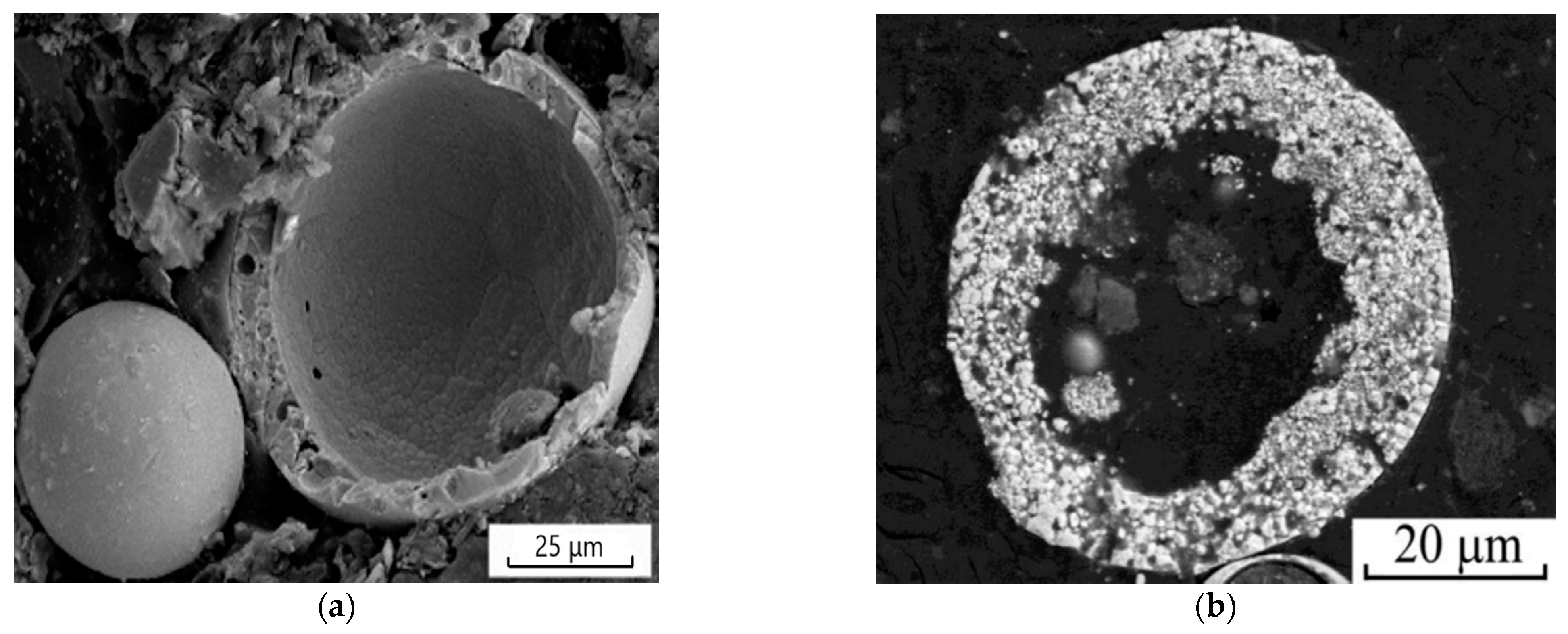
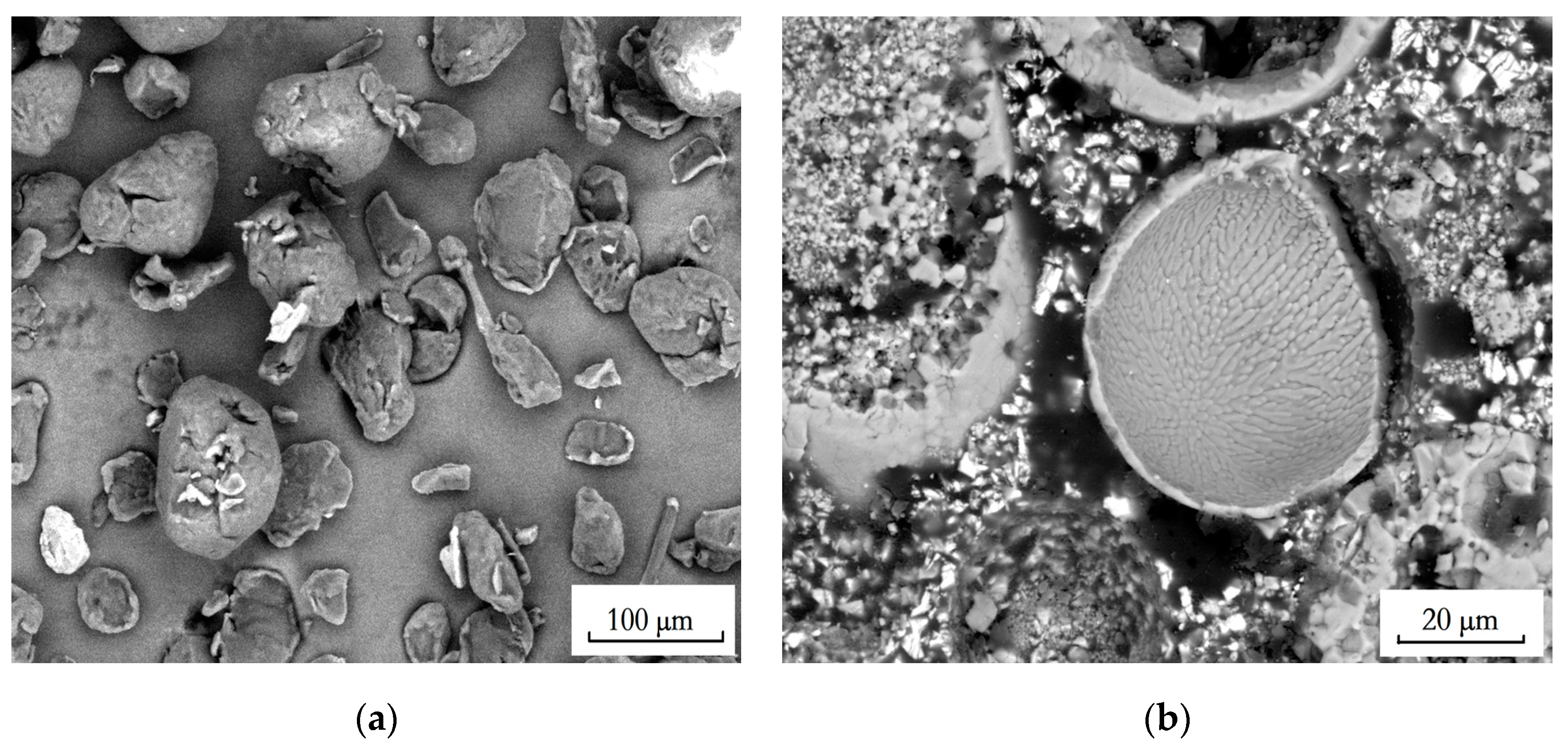
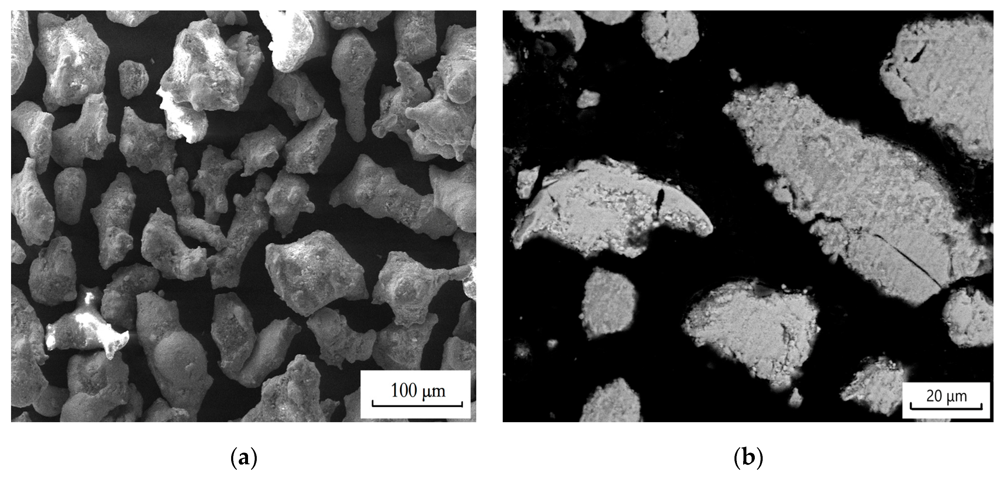
2.1. Powder and Coating Deposition

The hollow spherical 8YSZ powder (Metco 204 NS, Oerlikon, Schaumburg, IL, USA) with a mean size about 80 μm were chosen as feedstock. The powder has a globular shape as shown in Figure 1. Meanwhile, polypropylene powder (Guangdong Huachuang Plastic Chemical Industry Co.Ltd, Foshan, China) with a mean size of about 50 μm was chosen as pore forming agent as shown in Figure 2. Polypropylene powders with volume content of 10% and 15% were added into 8YSZ powders through ball milling (ND7—04, Nanda Tianzun Electronic Co., Ltd., Nanjing, China) at a roation speed of 120 rpm. The mixed polypropylene powder was controlled as 0%, 10%, 15% in volume. Incol 718 nickel alloy was used as the substrate. NiCoCrAlTaY powder (Amdry 997, Metco, Oerlikon, Schaumburg, IL, USA) was used as bond coat material with a mean size about 100 μm as shown in Figure 3. Before coating deposition, the Incol 718 substrate was sandblasted with 20–30 mesh brown corundum at the pressure of 0.8 Mpa which could clean on the substrate surface and improve the bonding strength between the substrate and the coating. The thermal barrier coatings were prepared through atmospheric plasma spraying (ZB-80, Beijing Zhengbang Co. Ltd., Beijing, China) with the coating processiong parameters shown in Table 1.

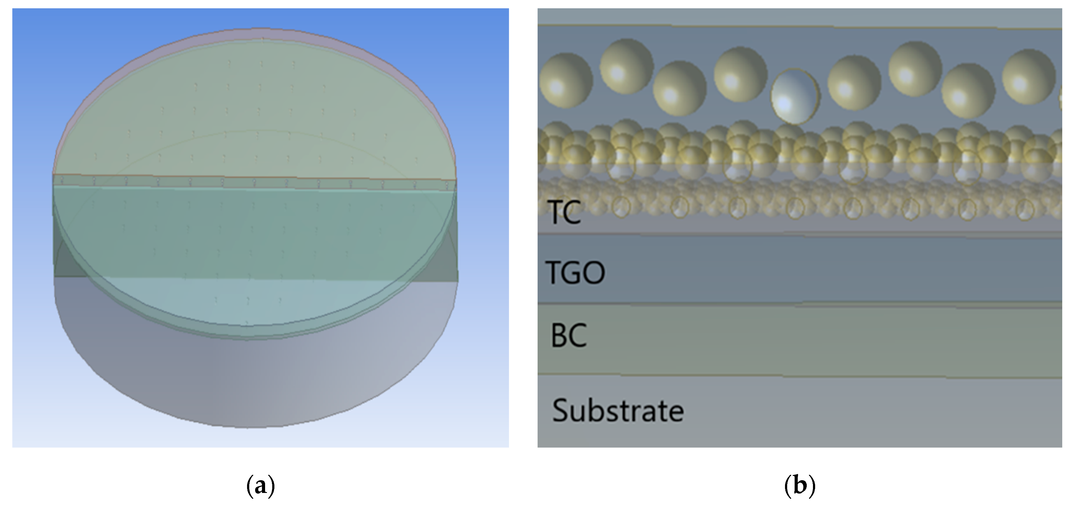
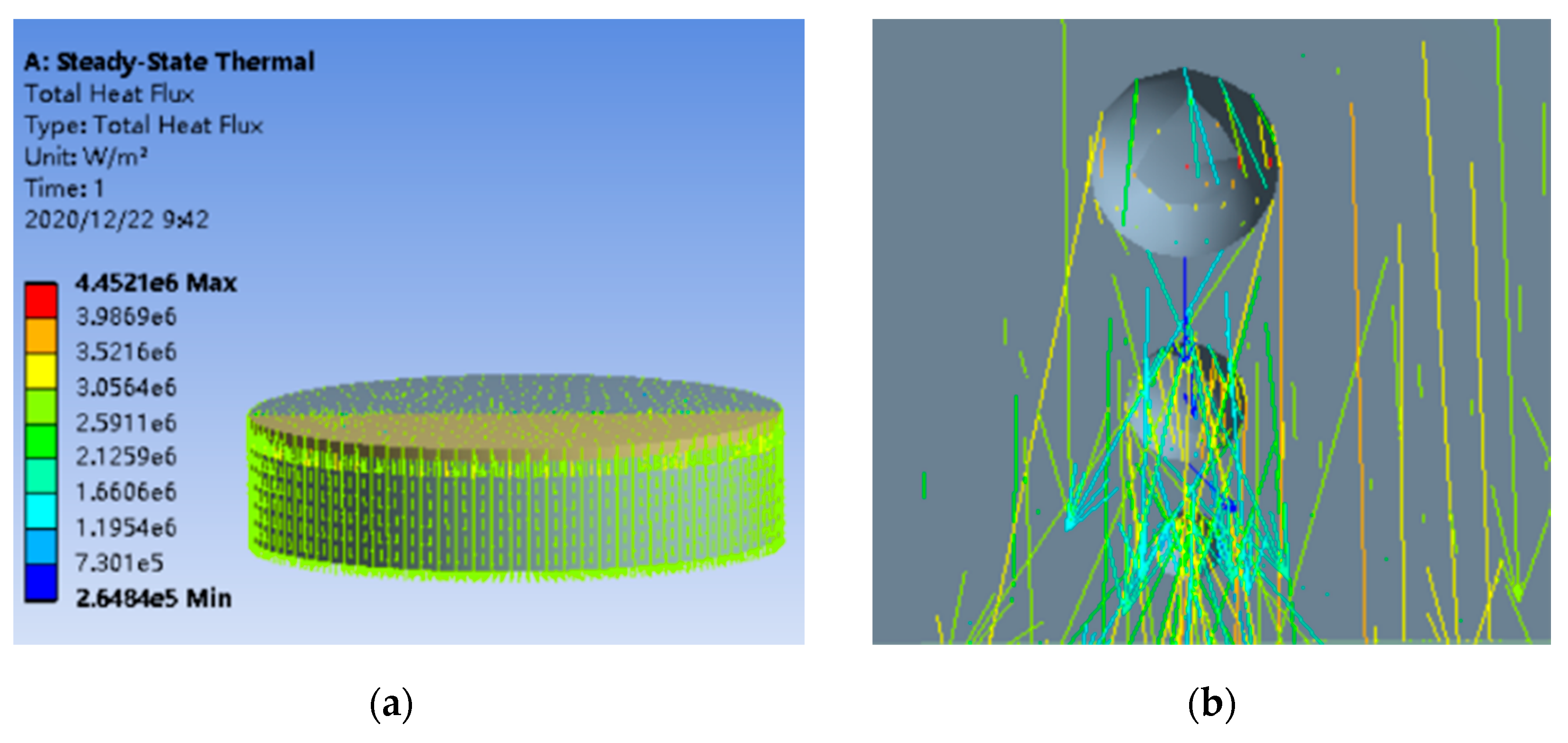
2.2. Thermal Conductivity Simulation

According to the real structure of TBCs, the TBC model was divided into four parts including the substrate, the bond coat, the thermally grown oxide and the top coat. To be consistent with the sample’s size of thermal conductivity tested through laser flash heating method, the diameter of the substrate was set as 12.6 mm and the thickness was 2.6 mm. The thick-nesses of the bond coat and the top coat were 0.1 mm and 0.2 mm, respectively. To simulate conveniently, the pores were idealized as spherical. To meet the real size scale in the multi-sized porous TBCs, the pore sizes were proposed to be set as 0.3 µm, 3 µm and 30 µm scales. The multi-sized pores distributed randomly in the top coat in real. While, to simulation simplely and conveniently, the radomly distributed multi-sized pores could be arranged in layers with the same ratio of the each sized pores as the real TBCs as well as the total porosities. The number of the three sized pores were set as 1000, 500, and 100 respectively. The total porosity was calculated to be 5%. The number of pores of different sizes would be adjusted to obtain different porosities according to the real ratio of the three scaled pores in the real multi-sized TBCs. The total porosities could be 5%, 10%, 15% and 20% by adjusting the number of pores at different sizes. The appropriate simulation model was based on the SEM-images and idealized to simple three directional distribution with the same ratio of each sized pores and total porositiesas the real TBCs. Meanwhile, the thickness of TGO was adjusted to the serving times according to the real thickness evolutions of the TGO during the long-term serving at high temperature. The model was shown in Figure 4. HYPERMESH software was used to mesh the model. Figure 5 shows the grids of the model after finite element grid generation.

2.3. Characterization

The morphology of the original powder and the microstructure of the multi-sized TBCs were examined by scanning electron microscopy (SEM; VEGA II-XMU, TESCAN, Brno, Czech Republic). The porosities of the TBCs was determined by image analysis including four steps: grayscale transformation, image preprocessing, image binarization and statistics porosity. The thermal conductivity of thermal barrier coating was tested through laser flash heating method with laser thermal conductivity meter (DLF-1200, TA, New Castle, DE, USA). The value of thermal conductivity is calculated according to Formula (1):
K = D C p ρ
In the formula, K is the thermal conductivity (W·m−1·K−1); D is the thermal diffusivity (m2·s−1); Cp is the specific heat (J·kg−1·K−1); ρ is the room temperature density of the sample (kg·m−3) (The Archimedes drainage method is used to measure the density).

3. Results

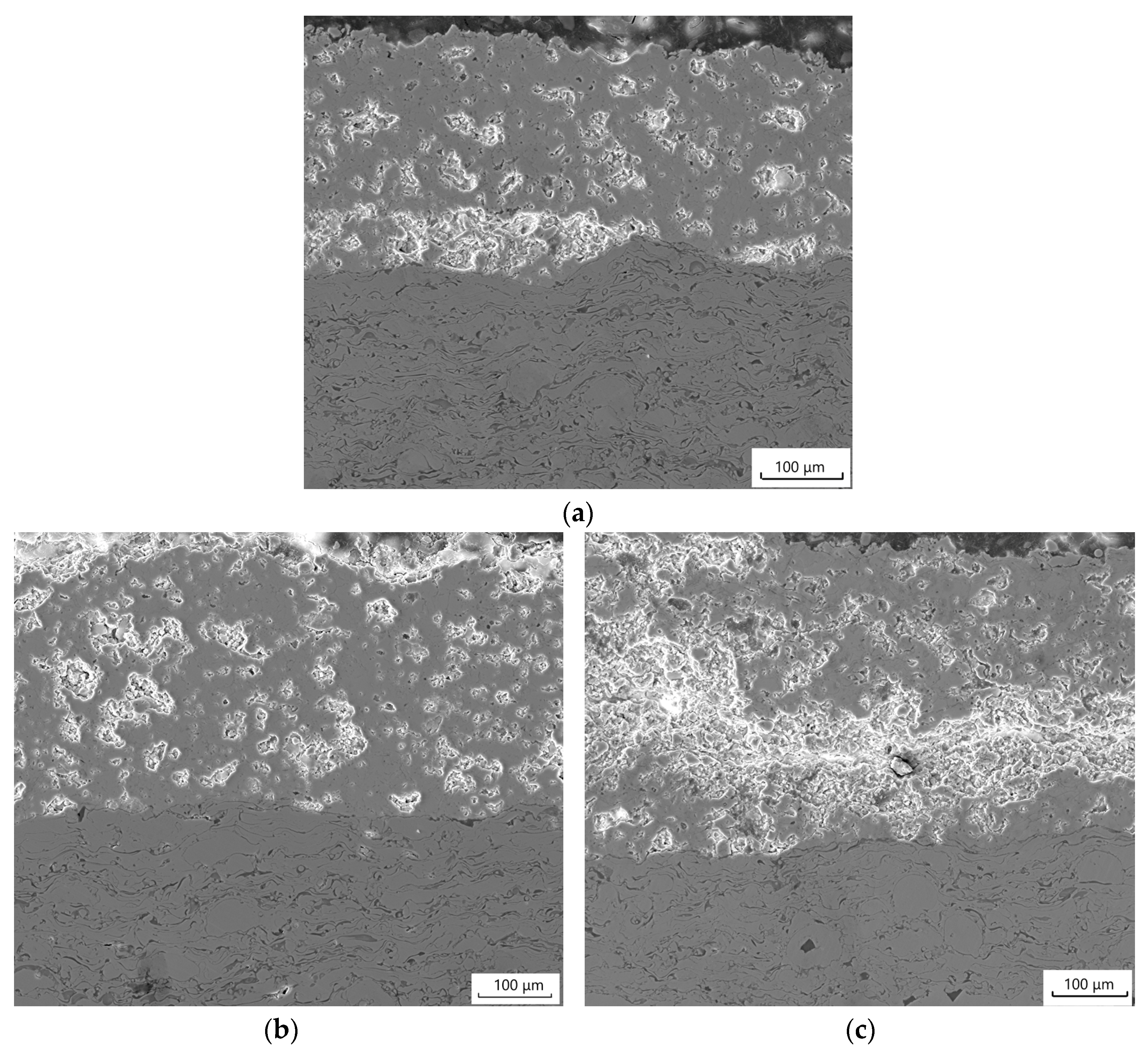
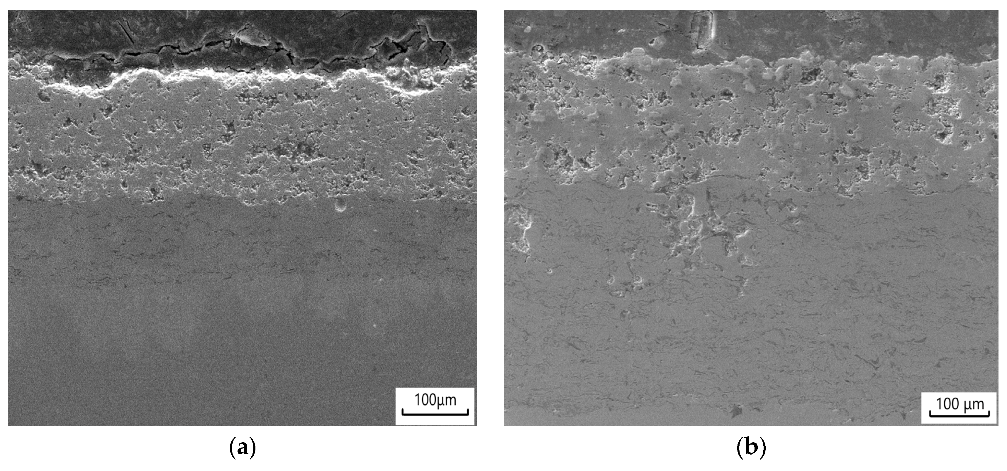
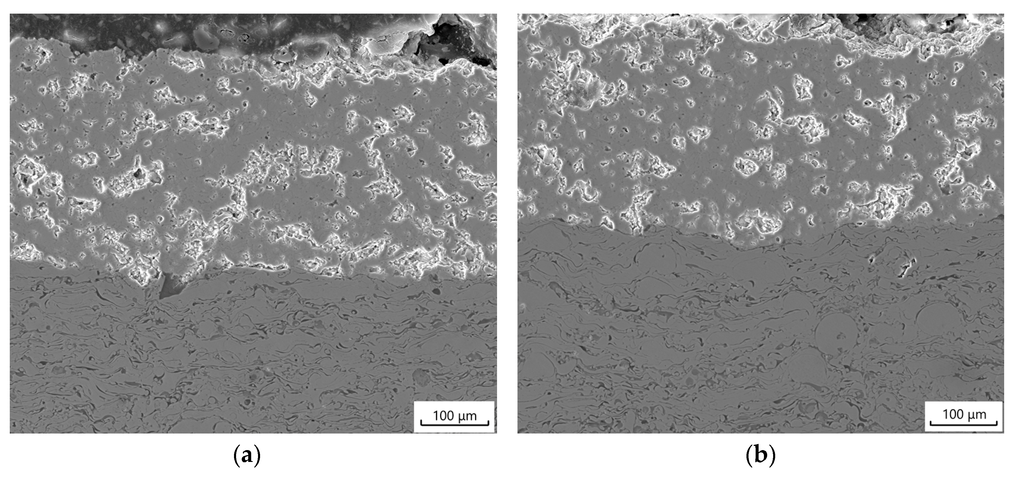
3.1. Microstructure of the Deposited Porous TBCs

Figure 6 shows the cross-sectional microstructures of the coatings prepared with Metco 204NS powder and 0%, 10% and 15% volume contents of pore former. It was found that the thickness of the top coat of the prepared thermal barrier coating was about 150 microns. Through computer-imaging analysis of the SEM figures, the porosities of the TBCs were 6.44%, 15.52%, and 22.25%, respectively.

3.2. Thermal Conductivity Computation of Porous TBCs after Long Time Serving

The temperatures, at which thermal conductivities were calculated, were set at 25 °C, 200 °C, 400 °C, 600 °C, 800 °C, 1000 °C, 1050 °C, 1100 °C. The thermal conductivity of the ceramic bulk was 2.3 W/m·K at 1100 °C and the thermal conductivity of the pores was 0.0257 W/m·K at 1100 °C, which were referred in literatures [9,10,11,12,13,14]. Figure 7 shows the temperature distribution isopleth of the coating at 1100 °C. The heating of the model presented a gradient distribution. Figure 8 shows the heat flux distribution nephogram of the coating at 1100 °C. Heat transferring in the coating was very high. While, heat transferring in the pores was low, which reflected that the existence of pores improved the heat insulation effects of the coatings.
The thermal conductivity of the constructured multi-sized porous TBCs was calculated through Ansys Software. The equivalent thermal conductivity of the TBCs was calculated according to the internal heat insulation and steady-state thermal conductivity. The thermal conductivities of the substrate structure and pores were certain. Meanwhile, the equivalent thermal conductivity of the constructured multi-sized porous TBCs model was calculated according to the simulation data. According to the Equations (2)–(4), the Equation (5) could be obtained:
q = k d T d x
q = λ Δ T d
q = J S
λ = q · d Δ T = J d · Δ T
where q was the heat flux, k was the scale constant, dT/dx was the temperature gradient, λ was the equivalent thermal conductivity, ΔT was the temperature change before and after heat conduction, d was the total distance of heat conduction, J was the heat flow and S was the heat conduction area.
Figure 9 shows the equivalent thermal conductivity of the top coat in TBCs with various porosities at different temperatures. The thermal conductivity of the TBCs decreased with the increase of serving temperature. Meanwhile, the thermal conductivity of the TBCs reduced with the increase of porosities. The existence of pores reduced the thermal conductivity of the coating and improved the thermal insulation effect of TBCs. Figure 10 shows the thermal conductivity of TBCs with different porosities at 1100 °C for different serving times. The thermal conductivity of the TBCs increased with the increase of the serving times. With the prolongation of serving times, the multi-sized pores would disappear partially among the boundaries of the deposited YSZ particles, which would bring out the increase of the TBCs. Large pores at micron and tens of microns will not disappear because the diffusion among YSZ particles could not penetrate across the micro-sized pores especially tens of microns sized large pores. Meanwhile, the nano-sized pores would disappear during the serving at high temperature, which would lead to the increase of the thermal conductivity in the multi-sized porous TBCs. Therefore, the thermal conductivity tended to be stable after about 60 days serving at 1100 °C, which was close to the bulk’s thermal conductivity [9]. With the further prolongation of serving times, the thermal conductivity of TBCs tended to be stable and unchanged. The porous structures tended to be stabilized which led to the unchanged thermal conduction and finally would ensure the stable operation of gas turbine engine.

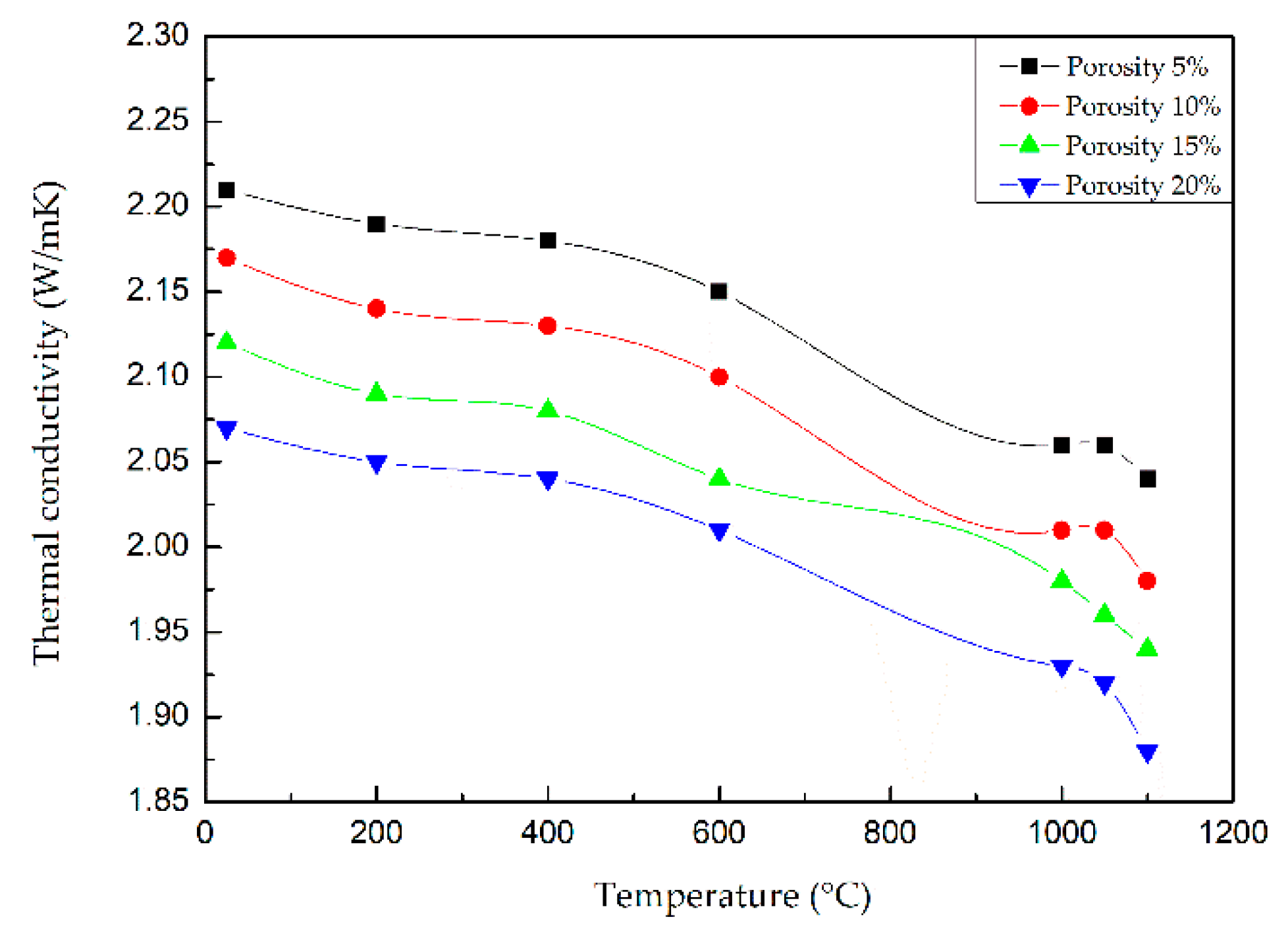
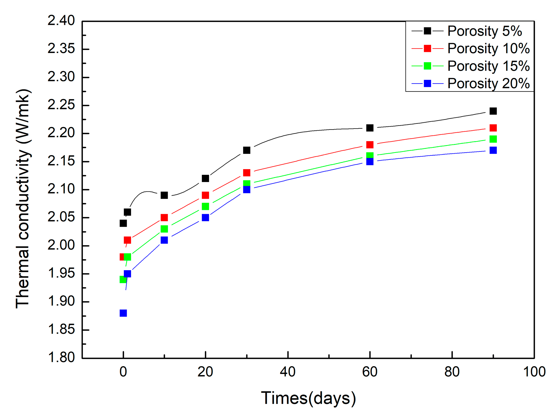
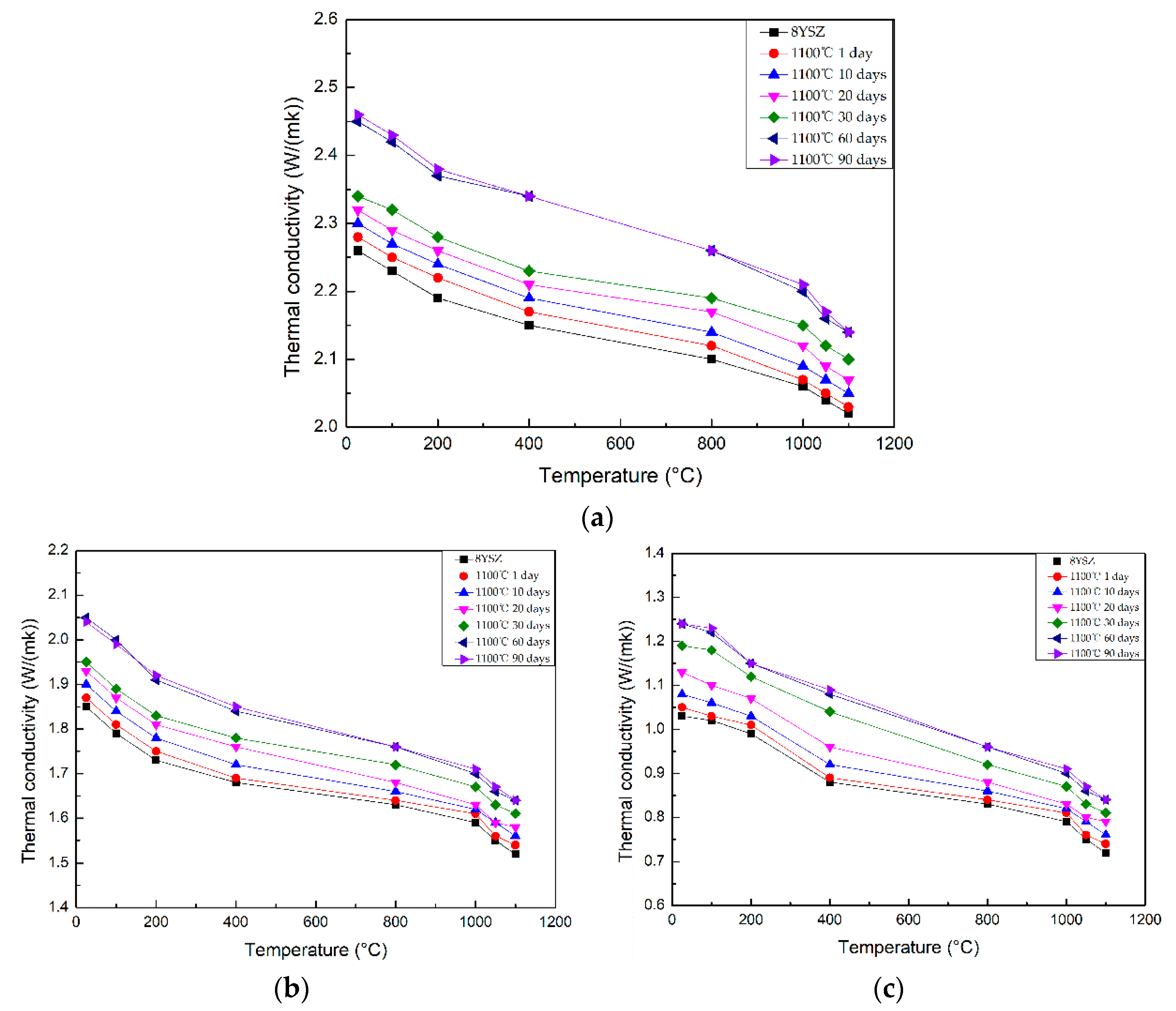
3.3. Thermal Conductivity of the Multi-Sized Porous TBCs after Long-Term Serving at High Temperature

Figure 11, Figure 12 and Figure 13 show the cross-sectional microstructures of the multi-sized TBCs with different contents of pore formers added at 1100 °C for different serving times. With the prolongation of serving times, the multi-sized pores would disappear partially among the boundaries of the deposited YSZ particles, which would bring out the increase of the TBCs. Large pores at micron and tens of microns would not disappear because the diffusion among YSZ particles could not penetrate across the micro-sized pores especially tens of microns sized large pores. When the serving time reached 30 days, the large pores in the coating began to connect with each other. When the serving time reached 60 days, the macroporous connections completed. At that time, the porosity in the coating tended to be stable and would not change with the extension of the serving time.
The tested thermal conductivities of the multi-sized TBCs with different porosities at 1100 ℃ for different serving times as a function of temperature were shown in Figure 14. The thermal conductivity of the bulk ceramic decreased with the increase of the serving temperature. The thermal conductivity of the TBCs decreased with the increase of the content of the polypropylene powder. The existence of large pores could effectively reduce the thermal conductivity. The thermal conductivity of the TBCs increased with the increase of the serving times. As comparison to the tested results, the calculated thermal conductivities of the multi-sized TBCs fitted to the tested ones very well after long-term serving at high temperatures.

4. Discussion

4.1. Diffusion in Multi-Sized Porous TBCs and Nano Pores Extinction Mechanism

Figure 15 shows the schematic model of the pore evolution mechanism of TBCs with multi-sized pores serving at 1100 °C for different times. With the prolongation of serving times, some of the multi-sized pores would disappear among the boundaries of the deposited YSZ particles, which would bring out the increase of the thermal conductivity of the TBCs. Large pores at micron and tens of microns would not disappear because the diffusion among YSZ particles could not penetrate across the micro-sized pores especially tens of microns sized large pores especially below the melting point of the materials. When the serving time reached 30 days, the large pores in micron size in the coating began to connect each other. According to the cross-sectional microstructure of the coating after a serving time of 60 days and 90 days as seen in Figure 11e,f, Figure 12e,f and Figure 13e,f, the macropores in micron size connected completely after 60 days’ serving at 1100 °C. At that time, the porosity in the coating tended to be stable and would not change with the extension of the serving time.

4.2. Thermal Conductivity Evolution Mechanism in Multi-Sized Porous TBCs

The thermal conductivity of 8YSZ material decreased with the increase of the serving temperature. The thermal conductivity of the porous TBCs decreased with the increase of the contents of the polypropylene powder added into the feedstocks. It reflected that the existence of pores could effectively reduce the thermal conductivity of the TBCs. The thermal conductivity of the TBCs increased with the increase of the serving times. The thermal conductivities of the multi-sized TBCs with 0%, 10% and 15% polypropylene added into Metco 204NS powders were 2.02 W/m·K, 1.52 W/m·K, 0.72 W/m·K, at 1100 °C without serving After 60 days of serving at 1100 °C, the thermal conductivities were 2.14 W/m·K, 1.64 W/m·K, 0.84 W/m·K, respectively.In general, the thermal conductivities increased a little after 60 days of serving at 1100 °C. Some scholars investigated that TBCs prepared with 8YSZ through APS had a porosity of 15% and a thermal conductivity of 0.8~0.86 W/m·K [29,30,31,32]. Although the pore’s effects on the thermal conductivity of TBCs were discussed in their works, the pore’s evolution on the thermal conductivity after long-term serving at high temperature. With the prolongation of serving times, some of the multi-sized pores would disappear among the boundaries of the deposited YSZ particles, which would bring out the increase of the thermal conductivity of the multi-sized TBCs. Large pores at micron and tens of microns would not disappear because the diffusion among YSZ particles could not penetrate across the micro-sized pores especially tens of microns sized large pores. Meanwhile, the nano-sized pores would disappear during the serving at high temperature, which would lead to the increase of the thermal conductivity of the multi-sized porous TBCs for its high activities of sintering at relative low temperature of 1100 °C [29], which was lower than the melting point of 8YSZ. Therefore, the thermal conductivity tended to be stable after about 60 days serving at 1100 °C, which was close to the bulk’s thermal conductivity [9]. With the further prolongation of serving times, the great gaps between the deposited particles with tens of microns pores could not be filled through diffusion at 1100 °C. The porous structures tended to be stable, which led to the thermal conductivity of TBCs unchanged and finally would ensure the stable operation of gas turbine engine. Large pores at microns and tens of microns would take the effects of sintering resistance, which was helpful to TBCs’ long-term serving at high temperature. Therefore, multi-sized porous TBCs could serve with a relatively stable thermal conductivity after a period high temperature serving in long-term serving at high temperature. Meanwhile, TBCs with closed pores had lower thermal conductivity than the conventional ones. During the serving of TBCs at high temperature for long terms, the TBCs would experience some changes especially fines pores which would affect the TBCs’ thermal conductivity as well as the thermal insulation. The thermal conductivity of the porous TBCs after long-term serving could be tested experimentaly. While, it would take long times in serving at high temperature. Simulations to evaluate the TBCs’ thermal conductivity in long-term serving at high temperature would save times and costs effectively.

5. Conclusions

Multi-sized porous thermal barrier coatings at micro and nano scales were prepared through hollow spherical powders of Metco 204NS and micron-sized polypropylene powders through atmospheric plasma spraying. The thermal conductivities of the multi-sized TBCs after a long-term serving at high temperature were tested through laser flash heating method and simulated through Ansys software. The calculated thermal conductivities of the multi-sized TBCs fitted to the tested ones very well after long-term serving at high temperatures. The thermal conductivity of the TBCs increased with the increase of the serving times. The thermal conductivity tended to be stable after about 60 days’ serving at 1000 °C, which was close to the bulk’s thermal conductivity. With the prolongation of serving times, the nano-sized pores would disappear during the serving at high temperature. Large pores at micron and tens of microns would not disappear, which were helpful to anti-sintering.

Author Contributions

Conceptualization, P.-H.G., S.-C.Z. and M.-X.L.; methodology, P.-H.G., S.-C.Z., B.-Y.C., M.-X.L., Y.-Q.L., L.J. and D.Z.; software, P.-H.G., S.-C.Z., C.J. and Y.-C.G.; validation, P.-H.G. and S.-C.Z.; formal analysis, P.-H.G. and S.-C.Z.; investigation, P.-H.G., S.-C.Z., B.Z., B.-Y.C., Y.-Q.L., L.J. and D.Z.; data curation, Z.Y.; writing—original draft preparation, S.-C.Z.; writing—review and editing, P.-H.G.; software, S.-C.Z., C.J. and Y.-C.G.; simulation, C.J. and Y.-C.G.; experiment, B.Z. and Q.-P.L.; project administration, J.-P.L.; funding acquisition, P.-H.G., and J.-P.L. All authors have read and agreed to the published version of the manuscript.

Funding

This work was funded by the National Natural Science Foundation of China (51771140), China Scholarship Council (201908610115), Shaanxi Key Science and Technology Innovation Team (2017KCT-05), The Youth Innovation Team of Shaanxi Universities: Metal Corrosion Protection and Surface Engineering Technology, Shaanxi Provincial Key Research and Development Project (2019ZDLGY05-09), Local Serving Special Scientific Research Projects of Shaanxi Provincial Department of Education (19JC022), Project of Yulin Science and Technology Bureau (2019-121).

Institutional Review Board Statement

Not applicable.

Informed Consent Statement

Not applicable.

Data Availability Statement

Not applicable.

Conflicts of Interest

The authors declare no conflict of interest.

References

  1. Padture, N.P.; Gell, M.; Jordan, E.H. Thermal barrier coatings for gas-turbine engine applications. Science 2002, 296, 280–284. [Google Scholar] [CrossRef]
  2. Evans, A.G.; Mumm, D.R.; Hutchinson, J.W.; Meier, G.H.; Pettit, F.S. Mechanisms controlling the durability of thermal barrier coatings. Prog. Mater. Sci. 2001, 46, 505–553. [Google Scholar] [CrossRef]
  3. Pia, G.; Casnedi, L.; Sanna, U. Porosity and pore size distribution influence on thermal conductivity of yttria-stabilized zirconia:Experimental findings and model predictions. Ceram. Int. 2016, 42, 5802–5809. [Google Scholar] [CrossRef]
  4. Schlichting, K.; Padture, N.; Jordan, E.; Gell, M. Failure modes in plasma-sprayed thermal barrier coatings. Mater. Sci. Eng. A-Struct. 2003, 342, 120–130. [Google Scholar] [CrossRef]
  5. Rabiei, A.; Evans, A.G. Failure mechanisms associated with the thermally grown oxide in plasma-sprayed thermal barrier coatings. Acta Mater. 2000, 48, 3963–3976. [Google Scholar] [CrossRef]
  6. Planques, P.; Vidal, V.; Lours, P.; Proton, V.; Crabos, F.; Huez, J.; Viguier, B. Mechanical and Thermo-physical Properties of Plasma-Sprayed Thermal Barrier Coatings: A Literature Survey. Oxid. Met. 2017, 88, 133–143. [Google Scholar] [CrossRef] [Green Version]
  7. Brinkiene, K.; Kezelis, R. Correlations between processing parameters and microstructure for YSZ films produced by plasma spray technique. J. Eur. Ceram. Soc. 2004, 24, 1095–1099. [Google Scholar] [CrossRef]
  8. Paul, S.; Cipitria, A.; Golosnoy, I.O.; Xie, L.; Dorfman, M.R.; Clyne, T.W. Effects of Impurity Content on the Sintering Characteristics of Plasma-Sprayed Zirconia. J. Therm. Spray Technol. 2007, 16, 798–803. [Google Scholar] [CrossRef] [Green Version]
  9. Nicholls, J.; Lawson, K.; Johnstone, A.; Rickerby, D. Methods to reduce the thermal conductivity of EB-PVD TBCs. Surf. Coat. Technol. 2002, 151–152, 383–391. [Google Scholar] [CrossRef] [Green Version]
  10. Sharma, A.; Witz, G.; Howell, P.C.; Hitchman, N. Interplay of the phase and the chemical composition of the powder feedstock on the properties of porous 8YSZ thermal barrier coatings. J. Eur. Ceram. Soc. 2021, 41, 3706–3716. [Google Scholar] [CrossRef]
  11. Carpio, P.; Borrell, A.; Salvador, M.D.; Gómez, A.; Martínez, E.; Sánchez, E. Microstructure and mechanical properties of plasma spraying coatings from YSZ feedstocks comprising nano- and submicron-sized particles. Ceram. Int. 2015, 41, 4108–4117. [Google Scholar] [CrossRef] [Green Version]
  12. Gao, Y.; Zhao, Y.; Yang, D.; Gao, J. A novel plasma-sprayed nanostructured coating with agglomerated-unsintered feedstock. J. Therm. Spray Technol. 2016, 25, 291–300. [Google Scholar] [CrossRef]
  13. Vardelle, A.M.; Moreau, C.; Akedo, J.; Ashrafizadeh, H.; Berndt, C.; Berghaus, J.O.; Boulos, M.; Brogan, J.; Bourtsalas, A.C.; Dolatabadi, A.; et al. The 2016 Thermal Spray Roadmap. J. Therm. Spray Technol. 2016, 25, 1376–1440. [Google Scholar] [CrossRef]
  14. Cao, X.Q.; Vassen, R.; Stoever, D. Ceramic materials for thermal barrier coatings. J. Eur. Ceram. Soc. 2004, 24, 1–10. [Google Scholar] [CrossRef]
  15. Taylor, R.; Brandon, J.R.; Paul, M. Microstructure, composition and property relationships of plasma-sprayed thermal barrier coatings. Surf. Coat. Technol. 1992, 50, 141–149. [Google Scholar] [CrossRef]
  16. Yang, M.; Zhu, Y.; Wang, X.; Guo, S.; Hu, J.; Zhao, L.; Chu, Y. Effect of five kinds of pores shape on thermal stress properties of thermal barrier coatings by finite element method. Ceram. Int. 2017, 43, 9664–9678. [Google Scholar] [CrossRef]
  17. Gao, P.-H.; Yang, G.-J.; Cao, S.-T.; Li, J.-P.; Yang, Z.; Guo, Y.-C. Heredity and variation of hollow structure from powders to coatings through atmospheric plasma spraying. Surf. Coat. Technol. 2016, 305, 76–82. [Google Scholar] [CrossRef]
  18. Tatsuo, S.; Hiroya, O.; Masayuki, A. A novel low-thermal-conductivity plasma sprayed thermal barrier coating controlled by large pores. Surf. Coat. Technol. 2016, 285, 120–127. [Google Scholar]
  19. Lv, B.; Jin, X.; Cao, J.; Xu, B.; Wang, Y.; Fang, D. Advances in numerical modeling of environmental barrier coating systems for gas turbines. J. Eur. Ceram. Soc. 2020, 40, 3363–3379. [Google Scholar] [CrossRef]
  20. Pekshev, P.Y.; Tcherniakov, S.V.; Arzhakin, N.A.; Rutskin, V.V. Plasma-sprayed multilayer protective coatings for gas turbine units. Surf. Coat. Technol. 1994, 64, 5–9. [Google Scholar] [CrossRef]
  21. Cernuschi, F.; Golosnoy, I.; Bison, P.; Moscatelli, A.; Vassen, R.; Bossmann, H.-P.; Capelli, S. Microstructural characterization of porous thermal barrier coatings by IR gas porosimetry and sintering forecasts. Acta Mater. 2013, 61, 248–262. [Google Scholar] [CrossRef]
  22. Zhou, C.; Wang, N.; Wang, Z.; Gong, S.; Xu, H. Thermal cycling life and thermal diffusivity of a plasma-sprayed nanostructured thermal barrier coating. Scr. Mater. 2004, 51, 945–948. [Google Scholar] [CrossRef]
  23. Wang, L.; Wang, Y.; Zhang, W.Q.; Sun, X.G.; He, J.Q.; Pan, Z.Y.; Wang, C.H. Finite element simulation of stress distribution and development in 8YSZ and double-ceramic-layer La2Zr2O7/8YSZ thermal barrier coatings during thermal shock. Appl. Surf. Sci. 2012, 258, 3540–3551. [Google Scholar] [CrossRef]
  24. Gilbert, A.; Kokini, K.; Sankarasubramanian, S. Thermal fracture of zirconia–mullite composite thermal barrier coatings under thermal shock: A numerical study. Surf. Coat Technol. 2008, 203, 91–98. [Google Scholar] [CrossRef]
  25. Bäker, M. Finite element simulation of interface cracks in thermal barrier coatings. Comput. Mater. Sci. 2012, 64, 79–83. [Google Scholar] [CrossRef]
  26. Sivakumar, S.; Praveen, K.; Shanmugavelayutham, G.; Yugeswaran, S.; Mostaghimi, J. Thermo-physical behavior of atmospheric plasma sprayed high porosity Lanthanum Zirconate coatings. Surf. Coat. Technol. 2017, 326, 173–182. [Google Scholar] [CrossRef]
  27. Yugeswaran, S.; Kobayashi, A.; Selvan, B.; Ananthapadmanabhan, P. In-flight behavior of lanthanum zirconate (La2Zr2O7) particles in gas tunnel type plasma jet and its coating properties. Vacuum 2013, 88, 139–143. [Google Scholar] [CrossRef]
  28. Kadam, N.R.; Karthikeyan, G.; Kulkarni, D.M. Effect of substrate rotation on the microstructure of 8YSZ thermal barrier coatings by EB-PVD. Mater. Today Proc. 2020, 28, 678–683. [Google Scholar] [CrossRef]
  29. Ruiji, Z.; Xing, Z.; Chen, X.; Li, H.; Fangwei, G.; Xin, W.; Xiaofeng, Z. Preparation of long-lifetime thermal barrier coatings and toughening mechanism by using hierarchy structured zirconia-based microspheres. J. Eur. Ceram. Soc. 2021, 41, 4625–4636. [Google Scholar]
  30. Zhou, F.; Wang, Y.; Liu, M.; Deng, C.; Zhang, X. Thermo-physical and thermal insulation properties of multi-scale nanostructured thermal barrier coatings using as-prepared t′-8YSZ feedstocks. Ceram. Int. 2019, 45, 24096–24103. [Google Scholar] [CrossRef]
  31. Cao, J.; Gao, K.; Cao, X.Y.; Jiang, B. Thermal shock behavior of a 8YSZ/CoCrAlYTaSi thermal sprayed barrier coating on GH202 superalloy. Ceram. Int. 2019, 46, 7489–7498. [Google Scholar] [CrossRef]
  32. Łatka, L.; Cattini, A.; Pawłowski, L.; Valette, S.; Pateyron, B.; Lecompte, J.-P.; Kumar, R.; Denoirjean, A. Thermal diffusivity and conductivity of yttria stabilized zirconia coatings obtained by suspension plasma spraying. Surf. Coat. Technol. 2012, 208, 87–91. [Google Scholar] [CrossRef]
Figure 1. Microstructure of Metco204NS powder: (a) globular; (b) Cross-sectional.
Coatings 11 01183 g001
Figure 2. Microstructure of polypropylene powder: (a) globular; (b) Cross-sectional.
Coatings 11 01183 g002
Figure 3. Microstructure of Amdry 997 powder: (a) globular; (b) Cross-sectional.
Coatings 11 01183 g003
Figure 4. Model of the TBCs: (a) whole; (b) pores.
Coatings 11 01183 g004
Figure 5. Gridding of models: (a) whole; (b) pores.
Coatings 11 01183 g005
Figure 6. Microstructure of the deposited layer porous TBCs: (a) 0%; (b) 10%; (c) 15%.
Coatings 11 01183 g006
Figure 7. Temperature distribution cloud.
Coatings 11 01183 g007
Figure 8. Heat flux distribution cloud: (a) whole; (b) pores.
Coatings 11 01183 g008
Figure 9. The claculated equivalent thermal conductivity of the top coat in TBCs with various porosities varied at different temperatures.
Coatings 11 01183 g009
Figure 10. Variation of calculated thermal conductivity with different porosities at 1100 °C for different serving time.
Coatings 11 01183 g010
Figure 11. The cross-section morphology of the top coats in TBCs with 0% pore former added at 1100 °C for different serving times: (a) 1 day; (b) 10 days; (c) 20 days; (d) 30 days; (e) 60 days; (f) 90 days.
Coatings 11 01183 g011aCoatings 11 01183 g011b
Figure 12. The cross-section morphology ofthe top coats in TBCs with 10% pore former added at 1100 °C for different serving times: (a) 1 day; (b) 10 days; (c) 20 days; (d) 30 days; (e) 60 days; (f) 90 days.
Coatings 11 01183 g012aCoatings 11 01183 g012b
Figure 13. The cross-section morphology of the top coats in TBCs with add 15% pore former at 1100 °C for different serving times: (a) 1 day; (b) 10 days; (c) 20 days; (d) 30 days; (e) 60 days; (f) 90 days.
Coatings 11 01183 g013aCoatings 11 01183 g013b
Figure 14. The tested thermal conductivities of the top coats in TBCs with different porosities at 1100 °C for different serving times: (a) 0%; (b) 10%; (c) 15%.
Coatings 11 01183 g014
Figure 15. Schematic diagram of the multi-sized pore evolution mechanism.
Coatings 11 01183 g015
Table 1. Plasma spraying parameters.
CoatingParameters
Bond CoatArc voltage (V)67
Arc current (A)540
H2 pressure (MPa)0.3
Ar flow (SLPM)36.7
Powder feeding rate (rad/min)3.5
Top CoatArc voltage (V)70
Arc current (A)600
H2 pressure (MPa)0.2
Ar flow (SLPM)34.5
Powder feeding rate (rad/min)3.7
Publisher’s Note: MDPI stays neutral with regard to jurisdictional claims in published maps and institutional affiliations.

