Article

Compositional Engineering of FAPbI3 Perovskite Added MACl with MAPbBr3 or FAPbBr3

Department of Electrical Engineering, Gachon University, 1342 Seongnam Daero, Seongnam-si 13120, Korea
*
Author to whom correspondence should be addressed.
Coatings 2021, 11(10), 1184; https://doi.org/10.3390/coatings11101184
Submission received: 15 September 2021 / Revised: 27 September 2021 / Accepted: 27 September 2021 / Published: 29 September 2021
(This article belongs to the Special Issue Optical Thin Film and Photovoltaic (PV) Related Technologies)

Abstract

:
Many attempts have been made to stabilize α-phase formamidinium lead iodide (α-FAPbI3) using mixed cations or anions with MA+, FA+, Br and I. A representative method is to stably produce α-FAPbI3 by adding methylammonium lead (MAPbBr3) to the light absorption layer of a perovskite solar cell and using methylammonium chloride (MACl) as an additive. However, in the perovskite containing MA+ and Br, the current density is lowered due to an unwanted increase in the bandgap; phase separation occurs due to the mixing of halides, and thermal stability is lowered. Therefore, in this study, in order to minimize the decrease in the composition ratio of FAPbI3 and to reduce MA+, the addition amount of MACl was first optimized. Thereafter, a new attempt was made to fabricate FAPbI3 perovskite by using formamidinium lead bromide (FAPbBr3) and MACl together as phase stabilizers instead of MAPbBr3. As for the FAPbI3-MAPbBr3 solar cell, the (FAPbI3)0.93(MAPbBr3)0.07 device showed the highest efficiency. On the other hand, in the case of the FAPbI3-FAPbBr3 solar cell, the (FAPbI3)0.99(FAPbBr3)0.01 solar cell with a very small FAPbBr3 composition ratio showed the highest efficiency with fast photovoltaic performance improvement and high crystallinity. In addition, the FAPbI3-FAPbBr3 solar cell showed a higher performance than the FAPbI3-MAPbBr3 solar cell, suggesting that FAPbBr3 can sufficiently replace MAPbBr3.

Graphical Abstract

1. Introduction

Perovskite solar cells (PSCs) are still one of the most popular fields and within a short period of time since their advent, they have achieved high power conversion efficiencies (PCEs) exceeding 25% with broader solar-light absorption through narrower bandgaps. Formamidinium lead iodide (FAPbI3) has the narrowest bandgap (1.45–1.51 eV) among lead halide perovskites and improved thermal stability compared to methylammonium lead iodide [1,2]. However, α-FAPbI3 (the FAPbI3 perovskite) is prone to phase change to δ-FAPbI3 (non-perovskite, hexagonal), which is thermodynamically more stable at room temperature. Yellow δ-FAPbI3 reduces the crystallinity of the FAPbI3 film, disrupting electron transport and reducing the performance of PSCs [3,4]. The first of two representative methods to overcome the phase transformation problem of α-FAPbI3 is the use of methylammonium chloride (MACl) as an additive in the perovskite precursor solution. MACl induces the growth of the (001) plane of α-FAPbI3 and improves the crystallinity of the perovskite [5,6]. Moreover, MACl can be removed by heating above 140 °C, which is essential for α-FAPbI3 synthesis [7]. Therefore, a MA+-free perovskite film can be produced using this method. The second method is to stably synthesize α-FAPbI3 by adding methylammonium lead bromide (MAPbBr3) with a cation smaller than FA+ to the perovskite composition [8]. Researchers have focused primarily on mixed cations or anions in an effort to improve the stability of α-FAPbI3. Therefore, FAPbI3-MAPbBr3 has been studied the most among all the processes for enhancing the phase stability of FAPbI3 and exhibited a higher PCE than the first method of adding MACl. In addition, MACl has been used together in the manufacture of FAPbI3-MAPbBr3 perovskite, and here MACl has been mainly used as ‘a mediator for high-crystallinity’. However, this method has problems such as reduced light absorption, increased bandgap due to MAPbBr3, and reduced thermal stability owing to MA+ ions, resulting in a low current density [9]. Although we attempted to stabilize the α-FAPbI3 phase without MA+ using Rb+ and Cs+, the resulting PCE was still low when compared to the PCE obtained using FA+ and MA+ [10,11]. Therefore, to further improve the performance of PSCs, a novel configuration capable of stabilizing α-FAPbI3 without MA+ while controlling the bandgap increase inherent in FAPbI3 is required.
We focused on the composition of mono-cation FAPbI3-FAPbBr3 perovskite, which can help improve α-FAPbI3 phase stability. However, δ-FAPbI3 was still found in the FAPbI3-FAPbBr3 film, resulting in poor solar cell performance. In this study, a new attempt was made to solve this problem by using MACl as an additive to increase the phase stability of α-FAPbI3 together with FAPbBr3. The combination of cations and anions added to the perovskite is important to improve the stability of FAPbI3 [12]. Therefore, FAPbI3-FAPbBr3 with MACl added stably produced α-FAPbI3 by combining MA+ and Br-. In addition, α-FAPbI3 films are stably fabricated by the formation of metastable two-dimensional MAFAPbI3Cl perovskite intermediates with high free energy due to the Cl- in the precursor solution [5]. The amount of MACl was first optimized and applied to the FAPbI3 film, and then MAPbBr3 or FAPbBr3 was used in the perovskite composition. MACl added FAPbI3-FAPbBr3 films showed a dramatic improvement in photovoltaic performance even with very small amounts of FAPbBr3. In addition, FAPbI3-FAPbBr3 PSCs showed a relatively high current density based on a smaller increase in FAPbI3 intrinsic bandgap than FAPbI3-MAPbBr3 PSCs, suggesting that FAPbBr3 could be used as a sufficient replacement for MAPbBr3.

2. Materials and Methods

2.1. Materials

FTO glass (7 Ω sq-1, Wooyang GMS), titanium diisopropoxide bis(acetylacetone) (75 wt.% in isopropanol, Sigma-Aldrich, St. Louis, MO, USA), 1-butyl alcohol (99%, Sigma-Aldrich, St. Louis, MO, USA), TiO2 paste (18 NR-T, Greatcell solar, Queanbeyan, Australia), N,N-dimethylformamide (DMF, 99.8%, Sigma-Aldrich, St. Louis, MO, USA), dimethyl sulfoxide (DMSO, ≥99.9%, Sigma-Aldrich, St. Louis, MO, USA), ethyl alcohol (≥99.5, Sigma-Aldrich, St. Louis, MO, USA), chlorobenzene (99.8%, Sigma-Aldrich, St. Louis, MO, USA), lead(II) iodide (99.999% trace metals basic, Sigma-Aldrich, St. Louis, MO, USA), lead(II) bromide (99.999% trace metals basic, Sigma-Aldrich, St. Louis, MO, USA), formamidinium iodide (FAI, greatcellsolar, Queanbeyan, Australia), methylammonium bromide (MABr, greatcellsolar, Queanbeyan, Australia), formamidinium bromide (FABr, greatcellsolar, Queanbeyan, Australia), methylammonium hydrochloride (MACl, greatcellsolar, Queanbeyan, Australia), toluene (99.9%, Sigma-Aldrich, St. Louis, MO, USA), 2,2′,7,7′-tetrakis[N,N-di(4-methoxyphenyl)amino]-9,9′-spirobifluorene (spiro-OMeTAD, 99%, Sigma-Aldrich, St. Louis, MO, USA), bis(trifluoromethane)-sulfonimide lithium salt (Li-TSFI; ≥99.0%, Sigma-Aldrich, St. Louis, MO, USA), acetonitrile (99.93%, Sigma-Aldrich, St. Louis, MO, USA), 4-tertbutylpyridine (98%, Sigma-Aldrich, St. Louis, MO, USA) were used. All reagents were used as received without further purification.

2.2. Device Preparation

FTO glass was used as the substrate for fabricating the device. The substrates were sequentially washed with acetone, ethanol, and deionized water for 15 min each in an ultrasonic bath. To deposit the compact-TiO2 (c-TiO2) layer, 55 mL of a titanium diisopropoxide bis (acetyl acetonate)/1-butyl alcohol (1:10 v/v) solution was spin-coated. The substrate was then heated at 120 °C for 15 min. On top of the c-TiO2 layer, a mesoporous TiO2 (mp-TiO2) layer was spin-coated. TiO2 paste with an average nanoparticle size of 20 nm was dispersed in ethyl alcohol (1:6 w/w). The prepared FTO/c-TiO2/mp-TiO2 substrates were calcined at 500 °C for 1 h and then cooled to room temperature. To fabricate the perovskite layer, 1.4 mol of perovskite solution was prepared in a mixture of DMF and DMSO (8:1 v/v). MACl was then added to the prepared precursor solution. Each sample was spin-coated onto the mp-TiO2 layer at 4000 rpm for 20 s. During the spin coating, 200 μL of toluene was added dropwise using a pipette after spinning for 10 s. The film was heated on a hot plate at 150 °C for 10 min. The hole transport layer was prepared using spiro-OMeTAD in chlorobenzene (72.3 mg/mL), and 28.8 μL 4-tert-butyl pyridine and 17.5 μL Li-bis solution (520 mg Li-TFSI/1 mL acetonitrile) were added. Finally, a 60 nm thick gold electrode was deposited using a thermal evaporation system.

2.3. Characterization and Device Measurement

UV-vis absorption spectra were measured using an Agilent 8453 UV-vis spectrophotometer (Agilent 8453, Agilent Technologies, Santa Clara, CA, USA) at a scan rate of 494.95 [nm/min] in the wavelength range 200–1000 nm. Phases of the perovskite films formed on FTO/TiO2 were analyzed using an XRD Rigaku DMAX 2200 system (Rigaku, Tokyo, Japan) with Cu Kα radiation (λ = 0.1542 nm). XRD patterns were analyzed in five step sizes in the range 10–60° 2θ. The surfaces of the perovskite layer on the FTO/TiO2 and the cross-sections of the FTO/TiO2/perovskite/spiro-OMeTAD. were obtained using field-emission SEM (Hitachi S-4700, Tokyo, Japan). All SEM images were sputter coated with gold for conductivity and measured at an acceleration voltage of 15 kV and a probe current of 10 μA. All surface images were measured at 30k magnification at distances of 12.2 mm and 12.3 mm, and cross-sectional images were measured at 50k magnification at distances of 15.2 mm. J-V curves of the PSCs were measured using a solar simulator (Polaromix K201, Solar simulator LAB 50, McScience K3000, McScience, Gyeonggi-do, Korea) under one sun illumination (AM1.5G, 100 mWcm−2). The active area of the PSCs was calculated using an area of 0.053 cm−2.

3. Results and Discussion

3.1. FAPbI3 Perovskite Solar Cells with MACl

To determine the optimal composition ratio of MAPbBr3 and FAPbBr3, five devices were prepared under various MACl conditions (0–50 mol%, or 0–50-MACl). Here, we designed a PSC with a fluorine-doped tin oxide (FTO)/TiO2/perovskite/spiro-OMeTAD/Au structure. Figure 1a shows the current density-voltage (J-V) curves for the perovskite device for different amounts of MACl. A summary of the photovoltaic properties of 0–50-MACl PSCs is presented in Table 1. The device without MACl exhibited an open-circuit voltage (VOC) of 0.831 V, a short-circuit current density (JSC) of 16.696 mAcm−2, a fill factor (FF) of 40.105%, and a PCE of 5.567%. The addition of MACl to the α-FAPbI3 film increased the overall efficiency of all devices by stabilizing α-FAPbI3 and improving the crystallinity [13]. The 40-MACl perovskite film exhibited the highest PCE of 15.379% with a VOC of 0.908 V, a JSC of 24.181 mAcm−2, and an FF of 70.037%, indicating that the optimal MACl addition amount was 40 mol% (Table 1). However, as the MACl concentration increased to 50 mol%, the PCE decreased to 12.989%. The XRD pattern of the α-FAPbI3 film (Figure 1b) by MACl concentration shows two characteristic peaks of α-FAPbI3 at 13.95°, 24.26° and 28.12°, which are attributed to the (001) (111) (002) plane, along with one peak at 11.8° that corresponds to δ-FAPbI3. In addition, the peak observed at 12.63° and 26.50° corresponds to lead iodide (PbI2) residue due to incomplete reaction between PbI2 and formamidinium iodide (FAI) in a perovskite precursor solution prepared by a stoichiometric method. The noticeable difference in the 2θ peak intensity of the α-FAPbI3 (001) (002) plane shows an improvement of the crystallinity of the perovskite, which sharply increases with the increase of the MACl. In addition, the peak corresponding to δ-FAPbI3 almost disappeared with the addition of MACl.

3.2. FAPbI3-MAPbBr3 Perovskite Solar Cells

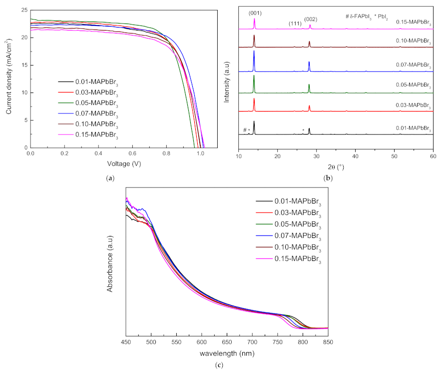
Using the optimized MACl condition, 12 devices were fabricated with various composition ratios of MAPbBr3 and FAPbBr3, which were used as light absorption layers to improve the phase stability of α-FAPbI3 and improve the performance of PSCs. Figure 2a shows the J-V curves of the (FAPbI3)1−X(MAPbBr3)X perovskite (renamed X-MAPbBr3) device. A summary of the photovoltaic properties of the PSCs according to the composition ratio of MAPbBr3 is presented in Table 2. The 0.07-MAPbBr3 film exhibited the highest PCE of 16.301% with a VOC of 1.017 V, a JSC of 22.196 mAcm−2, and an FF of 72.176%. In contrast, the PCE of the commonly used composition ratios, namely, 0.10-MAPbBr3 and 0.15-MAPbBr3, decrease gradually to 15.372% and 14.826%, respectively, which is attributed to the high series resistance (RS) [14,15,16,17]. The existence of α-FAPbI3 in the produced perovskite films was confirmed from the XRD pattern of the X-MAPbBr3 film (Figure 2b), which also showed that the crystallinity of the perovskite film improved with increasing the amount of MAPbBr3. However, as the composition ratio of MAPbBr3 increased to 0.10 and 0.15, the perovskite crystallinity decreased. In addition, the α-FAPbI3 peak shifted to a higher degree of diffraction with increasing amount of MAPbBr3. Figure 2c shows the absorbance of the X-MAPbBr3 perovskite film. The light absorption coefficient improved with the increasing amount of MAPbBr3 in the X-MAPbBr3 perovskite film. In particular, 0.07-MAPbBr3 showed the highest absorbance. On the other hand, 0.10- and 0.15-MAPbBr3 showed lower absorbance. When increasing the amount of MAPbBr3, which has a wider bandgap than FAPbI3 in the X-MAPbBr3 perovskite film, the absorbance gradually blue-shifted in the 750–850 nm wavelength region [18,19].

3.3. FAPbI3-FAPbBr3 Perovskite Solar Cells

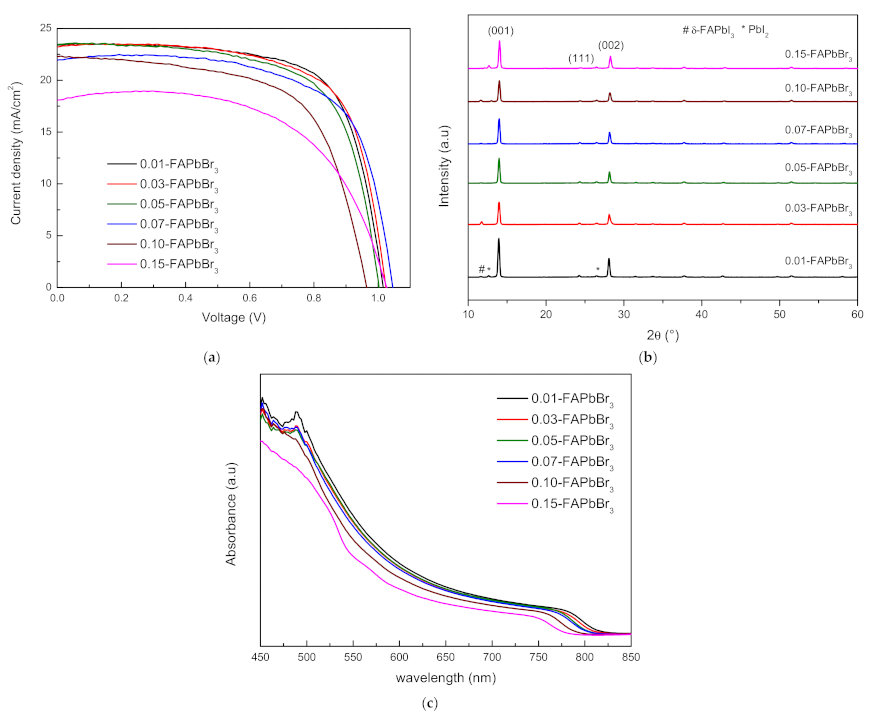
Figure 3a shows the J-V curve of the (FAPbI3)1−X(FAPbBr3)X perovskite (renamed X-FAPbBr3) device with 40 mol% MACl. A summary of the photovoltaic properties of X-FAPbBr3 is presented in Table 3. Surprisingly, despite the very small composition ratio of FAPbBr3, the 0.01-FAPbBr3 film exhibited an outstanding PCE of 16.569% with a VOC of 1.016 V, a JSC of 23.413 mA·cm−2, and an FF of 69.622%. The enhanced VOC of 1–15-FAPbBr3 can be attributed to the increase in the bandgap and the decrease in the electron-hole recombination at the interface between the perovskite film and the hole transport layer and electron transport layer [20,21]. Figure 3b shows the XRD pattern of the X-FAPbBr3 perovskite film. The 2θ peaks at 13.95°, 26.50°, and 28.12° in the XRD patterns confirm the existence of α-FAPbI3 in the fabricated perovskite film. The XRD pattern confirmed that the 0.01-FAPbBr3 film had the highest crystallinity. Thereafter, when increasing the amount of FAPbBr3, the intensity of the perovskite peak decreased. As with X-MAPbBr3, it was confirmed that as the composition ratio of FAPbBr3 increased, the diffraction peak of the (001) plane shifted to a larger angle [22]. Figure 3c shows the absorbance of the X-FAPbBr3 perovskite film. The 0.01-FAPbBr3 film had the highest absorbance. Subsequently, the absorbance gradually decreased as the FAPbBr3 content of the X-FAPbBr3 film increased. These results are responsible for the progressive decrease in JSC with an increasing concentration of FAPbBr3 (Table 2) [23]. In the 750–850 nm wavelength range, the absorbance of the X-FAPbBr3 film blue-shifted with increasing FAPbBr3, which has a wider bandgap similar to X-MAPbBr3.

3.4. Comparison of FAPbI3-FAPbBr3 and FAPbI3-MAPbBr3 Perovskite Solar Cells

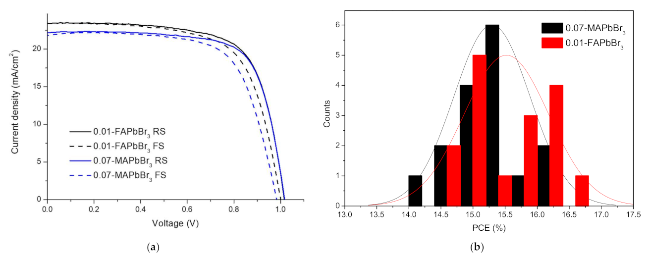
In Table 4, the difference between RS and FF of the optimized composition of FAPbI3-MAPbBr3 and FAPbI3-FAPbBr3 perovskite solar cells was not significant, indicating that the manufactured cells had similar stability [24,25]. Figure 4a,b shows the surface image of the perovskite films. The average grain sizes of 0.01-FAPbBr3 and 0.07-MAPbBr3 were approximately 769 nm and 652 nm, respectively. The difference in grain size between 0.01-FAPbBr3 and 0.07-MAPbBr3 affects JSC based on the difference in light absorption. [26]. Figure 4c is a cross-sectional SEM image of PSCs without the top electrode. The thickness of TiO2/perovskite/Spiro-OMeTAD is 240 nm, 348 nm, and 244 nm, respectively. As shown in Figure 5a, the JSC difference between 0.01-FAPbBr3 and 0.07-MAPbBr3 is clearly visible. This is considered to be due to the difference in the grain size, as mentioned above [27]. In addition, 0.01-FAPbBr3 shows reduced hysteresis compared to 0.07-MAPbBr3. The hysteresis index (HI, listed in Table 4) was extracted using the equation in [28]. The 0.07-MAPbBr3 device showed a significant PCE difference between 14.745% (forward) and 16.301% (reverse). The 0.01-FAPbBr3 device has a low hysteresis effect with PCEs of 16.569% and 15.656% for the reverse and forward directions, respectively. That is, the HI decreased from 0.095 to 0.055. The normal distribution model was applied to the histogram shown in Figure 5b. Both histograms show that the 0.01-FAPbBr3-based device exhibited improved solar cell performance compared to the 0.07-MAPbBr3-based device.

4. Conclusions

In this study, the addition amount of MACl was first optimized to reduce the dependence of MAPbBr3 or FAPbBr3 on the phase stability enhancement of FAPbI3. The 40-MACl device had a champion PCE of 15.379%, and 40 mol% MACl addition was adopted for the FAPbI3-MAPbBr3 and FAPbI3-FAPbBr3 films. MAPbBr3 or FAPbBr3 not only accelerated the δ to α phase transformation process of the FAPbI3 perovskite film, but also improved the crystallinity and formed a uniform perovskite film. Among the FAPbI3-MAPbBr3 PSCs, the 0.07-MAPbBr3 device had the highest PCE of 16.301% and higher photovoltaic performance than the commonly used 0.10- and 0.15-MAPbBr3 devices. Among the FAPbI3-FAPbBr3 devices, 0.01-FAPbBr3 showed the PCE of 16.569% even with the lowest FAPbBr3. Interestingly, the 0.01-FAPbBr3 device, which was not adopted due to its low performance, was more efficient than the 0.07-MAPbBr3 device and exhibited a suppressed hysteresis effect.

Author Contributions

Funding acquisition, H.W.C.; onvestigation, S.H.J.; supervision, H.W.C.; validation, H.W.C.; writing—original draft, S.H.J.; writing—review & editing, H.W.C. All authors have read and agreed to the published version of the manuscript.

Funding

This research was supported by the Basic Science Research Capacity Enhancement Project through the Korea Basic Science Institute (National Research Facilities and Equipment Center) grant funded by the Ministry of Education (2019R1A6C1010016). This work was supported by the Korea Institute of Energy Technology Evaluation and Planning (KETEP) and the Ministry of Trade, Industry & Energy (MOTIE) of the Republic of Korea (No. 20194030202290).

Institutional Review Board Statement

Not applicable.

Informed Consent Statement

Not applicable.

Data Availability Statement

Not applicable.

Conflicts of Interest

The authors declare no conflict of interest.

References

  1. Han, Q.; Bae, S.H.; Sun, P.; Hsieh, Y.T.; Yang, Y.; Rim, Y.S.; Zhao, H.; Chen, Q.; Shi, W.; Li, G. Single crystal formamidinium lead iodide (FAPbI3): Insight into the structural, optical, and electrical properties. Adv. Mater. 2016, 28, 2253–2258. [Google Scholar] [CrossRef] [PubMed]
  2. Eperon, G.E.; Stranks, S.D.; Menelaou, C.; Johnston, M.B.; Herz, L.M.; Snaith, H.J. Formamidinium lead trihalide: A broadly tunable perovskite for efficient planar heterojunction solar cells. Energy Environ. Sci. 2014, 7, 982–988. [Google Scholar] [CrossRef]
  3. Su, J.; Zheng, X.; Lang, X.; Han, R.; Cai, H.; Ni, J.; Zhang, J.; Qiu, J. Effect of precursor solution ageing time on the photovoltaic performance of perovskite solar cells. Funct. Mater. Lett. 2021, 14, 2151025. [Google Scholar] [CrossRef]
  4. Koh, T.M.; Fu, K.; Fang, Y.; Chen, S.; Sum, T.C.; Mathews, N.; Mhaisalkar, S.G.; Boix, P.P.; Baikie, T. Formamidinium-containing metal-halide: An alternative material for near-IR absorption perovskite solar cells. J. Phys. Chem. C 2014, 118, 16458–16462. [Google Scholar] [CrossRef]
  5. Zhang, T.; Xu, Q.; Xu, F.; Fu, Y.; Wang, Y.; Yan, Y.; Zhang, L.; Zhao, Y. Spontaneous low-temperature crystallization of α-FAPbI3 for highly efficient perovskite solar cells. Sci. Bull. 2019, 64, 1608–1616. [Google Scholar] [CrossRef]
  6. Yang, G.; Zhang, H.; Li, G.; Fang, G. Stabilizer-assisted growth of formamdinium-based perovskites for highly efficient and stable planar solar cells with over 22% efficiency. Nano Energy 2019, 63, 103835. [Google Scholar] [CrossRef]
  7. Kim, M.; Kim, G.-H.; Lee, T.K.; Choi, I.W.; Choi, H.W.; Jo, Y.; Yoon, Y.J.; Kim, J.W.; Lee, J.; Huh, D. Methylammonium chloride induces intermediate phase stabilization for efficient perovskite solar cells. Joule 2019, 3, 2179–2192. [Google Scholar] [CrossRef]
  8. Hanusch, F.C.; Wiesenmayer, E.; Mankel, E.; Binek, A.; Angloher, P.; Fraunhofer, C.; Giesbrecht, N.; Feckl, J.M.; Jaegermann, W.; Johrendt, D. Efficient planar heterojunction perovskite solar cells based on formamidinium lead bromide. J. Phys. Chem. Lett. 2014, 5, 2791–2795. [Google Scholar] [CrossRef]
  9. Smecca, E.; Numata, Y.; Deretzis, I.; Pellegrino, G.; Boninelli, S.; Miyasaka, T.; La Magna, A.; Alberti, A. Stability of solution-processed MAPbI3 and FAPbI3 layers. Phys. Chem. Chem. Phys. 2016, 18, 13413–13422. [Google Scholar] [CrossRef]
  10. Min, H.; Kim, M.; Lee, S.-U.; Kim, H.; Kim, G.; Choi, K.; Lee, J.H.; Seok, S.I. Efficient, stable solar cells by using inherent bandgap of α-phase formamidinium lead iodide. Science 2019, 366, 749–753. [Google Scholar] [CrossRef]
  11. Bu, T.; Li, J.; Li, H.; Tian, C.; Su, J.; Tong, G.; Ono, L.K.; Wang, C.; Lin, Z.; Chai, N.; et al. Lead halide–templated crystallization of methylamine-free perovskite for efficient photovoltaic modules. Science 2021, 372, 1327–1332. [Google Scholar] [CrossRef]
  12. Jeon, N.J.; Noh, J.H.; Yang, W.S.; Kim, Y.C.; Ryu, S.; Seo, J.; Seok, S.I. Compositional engineering of perovskite materials for high-performance solar cells. Nature 2015, 517, 476–480. [Google Scholar] [CrossRef]
  13. Xie, F.; Chen, C.-C.; Wu, Y.; Li, X.; Cai, M.; Liu, X.; Yang, X.; Han, L. Vertical recrystallization for highly efficient and stable formamidinium-based inverted-structure perovskite solar cells. Energy Environ. Sci. 2017, 10, 1942–1949. [Google Scholar] [CrossRef]
  14. Reyna, Y.; Salado, M.; Kazim, S.; Pérez-Tomas, A.; Ahmad, S.; Lira-Cantu, M. Performance and stability of mixed FAPbI3(0.85) MAPbBr3(0.15) halide perovskite solar cells under outdoor conditions and the effect of low light irradiation. Nano Energy 2016, 30, 570–579. [Google Scholar] [CrossRef] [Green Version]
  15. Li, Y.; Zhang, T.; Xu, F.; Wang, Y.; Li, G.; Yang, Y.; Zhao, Y. CH3NH3Cl assisted solvent engineering for highly crystallized and large grain size mixed-composition (FAPbI3)0.85(MAPbBr3)0.15 perovskites. Crystals 2017, 7, 272. [Google Scholar] [CrossRef]
  16. Mei, Y.; Liu, H.; Li, X.; Wang, S. Hollow TiO2 spheres as mesoporous layer for better efficiency and stability of perovskite solar cells. J. Alloys Compd. 2021, 866, 158079. [Google Scholar] [CrossRef]
  17. Mundhaas, N.; Yu, Z.J.; Bush, K.A.; Wang, H.P.; Häusele, J.; Kavadiya, S.; McGehee, M.D.; Holman, Z.C. Series resistance measurements of perovskite solar cells using Jsc–Voc measurements. Sol. RRL 2019, 3, 1800378. [Google Scholar] [CrossRef]
  18. Isikgor, F.H.; Li, B.; Zhu, H.; Xu, Q.; Ouyang, J. High performance planar perovskite solar cells with a perovskite of mixed organic cations and mixed halides, MA1−xFAxPbI3−yCly. J. Mater. Chem. A 2016, 4, 12543–12553. [Google Scholar] [CrossRef] [Green Version]
  19. Fang, H.-H.; Adjokatse, S.; Shao, S.; Even, J.; Loi, M.A. Long-lived hot-carrier light emission and large blue shift in formamidinium tin triiodide perovskites. Nat. Commun. 2018, 9, 1–8. [Google Scholar] [CrossRef] [PubMed]
  20. Gharibzadeh, S.; Abdollahi Nejand, B.; Jakoby, M.; Abzieher, T.; Hauschild, D.; Moghadamzadeh, S.; Schwenzer, J.A.; Brenner, P.; Schmager, R.; Haghighirad, A.A. Record open-circuit voltage wide-bandgap perovskite solar cells utilizing 2D/3D perovskite heterostructure. Adv. Energy Mater. 2019, 9, 1803699. [Google Scholar] [CrossRef]
  21. Correa-Baena, J.-P.; Tress, W.; Domanski, K.; Anaraki, E.H.; Turren-Cruz, S.-H.; Roose, B.; Boix, P.P.; Grätzel, M.; Saliba, M.; Abate, A. Identifying and suppressing interfacial recombination to achieve high open-circuit voltage in perovskite solar cells. Energy Environ. Sci. 2017, 10, 1207–1212. [Google Scholar] [CrossRef]
  22. Slimi, B.; Mollar, M.; Assaker, I.B.; Kriaa, A.; Chtourou, R.; Marí, B. Synthesis characterization of perovskite FAPbBr3− xIx thin films for solar cells. Mon. Für Chem. -Chem. Mon. 2017, 148, 835–844. [Google Scholar] [CrossRef]
  23. Chen, L.-C.; Chen, J.-C.; Chen, C.-C.; Wu, C.-G. Fabrication and properties of high-efficiency perovskite/PCBM organic solar cells. Nanoscale Res. Lett. 2015, 10, 1–5. [Google Scholar] [CrossRef] [Green Version]
  24. Bao, X.; Wang, Y.; Zhu, Q.; Wang, N.; Zhu, D.; Wang, J.; Yang, A.; Yang, R. Efficient planar perovskite solar cells with large fill factor and excellent stability. J. Power Sources 2015, 297, 53–58. [Google Scholar] [CrossRef]
  25. Krishnan, U.; Kaur, M.; Kumar, M.; Kumar, A. Factors affecting the stability of perovskite solar cells: A comprehensive review. J. Photonics Energy 2019, 9, 021001. [Google Scholar]
  26. Kim, H.D.; Ohkita, H.; Benten, H.; Ito, S. Photovoltaic performance of perovskite solar cells with different grain sizes. Adv. Mater. 2016, 28, 917–922. [Google Scholar] [CrossRef] [PubMed] [Green Version]
  27. Gedamu, D.; Asuo, I.M.; Benetti, D.; Basti, M.; Ka, I.; Cloutier, S.G.; Federico, R.; Nechache., R. Solvent-antisolvent ambient processed large grain size perovskite thin films for high-performance solar cells. Sci. Rep. 2018, 8, 1–11. [Google Scholar] [CrossRef] [PubMed]
  28. Habisreutinger, S.N.; Noel, N.K.; Snaith, H.J. Hysteresis index: A figure without merit for quantifying hysteresis in perovskite solar cells. ACS Energy Lett. 2018, 3, 2472–2476. [Google Scholar] [CrossRef] [Green Version]
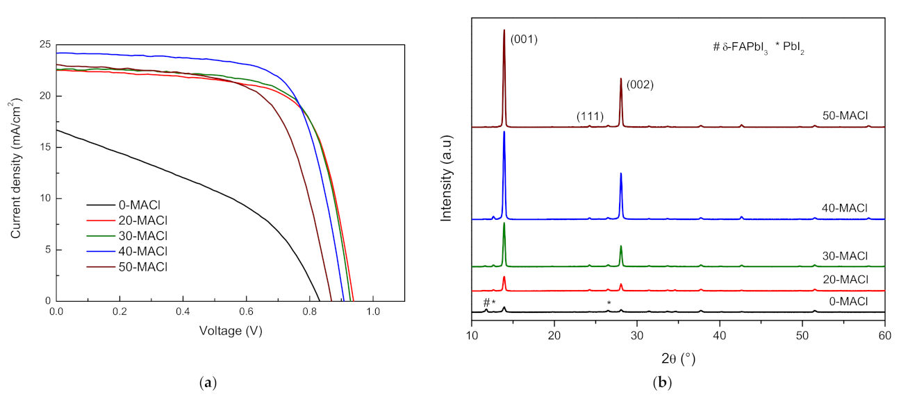
Figure 1. (a) Photocurrent density-voltage curve of the FAPbI3 PSCs at different MACl concentrations.; (b) XRD patterns of the 0-, 20-, 30-, 40-, and 50-MACl perovskite films.
Coatings 11 01184 g001
Figure 2. (a) Photocurrent density-voltage curve of the X-MAPbBr3 based PSCs. (b) XRD patterns of the X-MAPbBr3 perovskite film. (c) UV-vis absorption spectra of the X-MAPbBr3 film.
Coatings 11 01184 g002
Figure 3. (a) Photocurrent density-voltage curve of the X-FAPbBr3 based PSCs. (b) XRD patterns of the X-FAPbBr3 perovskite films. (c) UV-vis absorption spectra of the X-FAPbBr3 film.
Coatings 11 01184 g003
Figure 4. The surface FE-SEM images of (a) the 0.07-MAPbBr3 and (b) 0.01-FAPbBr3 perovskite film. (c) Cross-sectional FE-SEM images of the PSC.
Coatings 11 01184 g004
Figure 5. (a) Forward and reverse scans current density-voltage curve of the 0.07-MAPbBr3 and 0.01-FAPbBr3 based PSCs (hysteresis effect). (b) PCE distribution of the 32 PSCs.
Coatings 11 01184 g005
Table 1. Photovoltaic parameters of the best-performing FAPbI3 PSCs with various amounts of MACl.
SampleVOCJSCFFPCE (%)Rs(Ω)
0-MACl0.83116.69640.1055.567331.839
20-MACl0.93822.55068.98214.596119.269
30-MACl0.92922.59970.79114.859104.548
40-MACl0.90824.18170.03715.379109.747
50-MACl0.86923.07464.76812.989135.155
Table 2. Photovoltaic parameters of the best-performing X-MAPbBr3 PSCs.
SampleVOCJSCFFPCE (%)Rs(Ω)
0.01-MAPbBr31.00022.53869.59415.691120.472
0.03-MAPbBr30.98622.72970.18815.730113.333
0.05-MAPbBr30.96523.40770.87816.014109.144
0.07-MAPbBr31.01722.19672.17616.301116.721
0.10-MAPbBr31.00221.78570.41415.372122.829
0.15-MAPbBr31.02521.65167.76414.826147.174
Table 3. Photovoltaic parameters of the best-performing X-FAPbBr3 PSCs.
SampleVOCJSCFFPCE (%)Rs (Ω)
0.01-FAPbBr31.01623.41369.62216.569117.628
0.03-FAPbBr31.02523.22168.78116.364115.223
0.05-FAPbBr31.00323.48166.94815.766123.569
0.07-FAPbBr31.04521.93867.44615.468126.702
0.10-FAPbBr30.96522.27562.86113.508153.506
0.15-FAPbBr31.02718.05560.81411.274231.911
Table 4. Photovoltaic parameters of the best-performing X-FAPbBr3 PSCs.
SampleSweep DirectionVOCJSCFFPCE (%)RS(Ω)HI
0.01-FAPbBr3FS1.00123.42566.79715.656132.0240.055
RS1.01623.41369.62216.569117.628
0.07-MAPbBr3FS0.98321.83368.70214.745143.7290.095
RS1.01722.19672.17616.301116.721
Publisher’s Note: MDPI stays neutral with regard to jurisdictional claims in published maps and institutional affiliations.