Abstract
The selection of lining material for a steel ladle is important to heat preservation of molten steel. Aerogel insulation materials have very low thermal conductivity, however, they are rarely used in steel ladles. In this paper, the application of a new silica aerogel material on the steel ladle insulation layer is tested, and a new calculation method is designed to study its insulation effect. In other words, the ladle wall temperature is obtained by finite element model (FEM) and experiments, then the heat emission from the ladle wall is calculated by the Boltzmann mathematical model according to the ladle wall temperature, and the temperature loss of molten steel is calculated inversely according to the heat emission of ladle wall. Compared with the original steel ladle (comparison ladle), the application effect is analyzed. Due to the stable heat storage of the ladle wall after refining, the validity of the models are verified in ladle furnace (LF) process. The results show that the new calculation method is feasible, and the relevant parameter settings in the FEM and Boltzmann mathematical model are correct. Finally, after using the new aerogel insulation material, the temperature of molten steel is reduced by 16.67 °C, and the production cost is reduced by CNY 5.15/ton of steel.
1. Introduction
In the steelmaking process, the steel ladle is an extremely important piece of equipment. It has multi-functional uses, including temporary smelting, molten steel heat preservation and transportation [1,2]. In the context of the current global advocacy of energy conservation and emission reduction, the steel ladle is particularly important for the thermal insulation effect of molten steel. When the heat preservation effect of the steel ladle is poor [3,4,5]: (1). The steel ladle dissipates more heat and the temperature of molten steel drops quickly. To increase the temperature of the molten steel, higher power consumption is necessary, which will also lead to longer power supply time and more deoxidizer consumption. The corrosion of the refractory lining is accelerated, thus the steel ladle life is reduced and the cost is significantly increased; (2). The extension of the steelmaking time has led to lower steelmaking efficiency, insufficient production capacity and increased cost; (3). The surface temperature of the steel shell is increased, which increases the thermal fatigue effect of the steel shell and significantly reduces the service life of the steel shell; (4). Rapid heat dissipation of the steel ladle leads to increased temperature fluctuations of the molten steel, which has a very adverse effect on stable continuous casting and improving the yield of continuous casting slabs. In short, the steel ladle heat preservation effect is good, and it will have a positive effect on all aspects of production.
The steel ladle insulation layer plays a vital role in the temperature preservation of molten steel. There are many types of steel ladle insulation materials, mainly including asbestos panel, ordinary ceramic fiber panel, calcium silicate panel, clay brick and other materials [6,7,8]. At present, 10 mm or 20 mm thick asbestos sheets are mainly used for steel ladle insulating layers. For example, South Africa Iscor ltd and Indian Pat Industries Company uses 10 mm thickness asbestos sheets; China Hegang Iron and Steel Group, China Shandong Iron and Steel Group, and other enterprises use 20 mm thickness asbestos sheets [9,10]. However, these materials have a poor insulation effect, and the service life is short [11,12]. In recent years, the silica aerogel composite insulation panel (SACIP) has attracted great interest in thermal insulation applications due to its ultralow thermal conductivity [13,14] (see Figure 1), and is applied to the high temperature industry, gradually replacing the products with poor thermal insulation performance, high energy consumption and those that are harmful to the human body and the environment, such as glass fiber, rock, wool, and aluminum silicate fiber [15,16]. However, at present, the application of aerogel insulation materials in the metallurgical industry is relatively rare, and there are few researchers studying its application, especially calculating the influence of steel ladle insulation layer heat transfer on molten steel temperature. For example, in the period 2018–2020, Jia Changjiang, Sun Ye and others [17,18,19] measured the application of 10mm thickness Mk type aerogel insulation panel in 80-ton of steel ladle insulating layer in Hebei Iron and Steel Group and Tianjin Steel Plant, and achieved good results. However, they didn’t provide a calculation method for the thermal insulation of the aerogel composite insulation panel. It is only a general conclusion based on the actual measurement results. Moreover, the aerogel material and the thickness of the insulating layer were also quite different from the research in this paper, and the insulation and energy saving effects were not considered from the whole steelmaking process. In the course of the research, Romao, I and others [20] established a 2D heat transfer model of the ladle wall and obtained a better effect. However, they did not include the effect of free surface radiation. Taddeo [21] compared and analyzed the temperature drop rate of liquid steel between a traditional ladle and the one with an insulation layer in a steel plant. The results indicated that the speed of temperature drop of the latter was lower, that is to say, the heat preservation effect of the ladle with insulating lining structure was better, and 10.5% electric energy was saved. Others [22] used composite reflective insulation panels in the insulation layer, and used lightweight high-strength castables in the insulation layer, which significantly improved the performance of insulation of steel ladle, but the radiative heat and considered only convective heat transfer wasn’t addressed. Other researchers [23] have undertaken research of ladle heat preservation performance, molten steel temperature, ladle wall temperature and so on, but as an integrated approach, especially the research on the interaction of the three, hasn’t been adequately addressed. Therefore, based on the test ladle, in this paper, the thermal insulation performance of SACIP is studied comprehensively, that being the relationship between the temperature of molten steel, the temperature of the ladle wall and SACIP insulation efficiency, as well as the effect of using the test ladle on the cost compared with the original ladle (comparison ladle) were studied.

Figure 1.
Comparison of thermal conductivity of different insulation materials.
In this work, the surface temperature of the outer steel shell (OSS) and the temperature of the molten steel were measured with an infrared temperature measuring thermometer and a thermocouple temperature measuring thermometer, respectively. Then in the analysis process, the 2D heat transfer finite element model (FEM) of the ladle wall was established and analyzed by SOLIDWORKS 19.0 and ANSYS APDL software to study the temperature change of the ladle wall, then the temperature loss of molten steel was calculated by Boltzmann mathematical equation through the heat dissipation of the ladle wall. According to the measured temperature of molten steel and the ladle wall, the accuracy of the 2D heat transfer model and Boltzmann mathematical equation were verified. In the analysis process, the method used to measure the temperature of the molten steel and the temperature of the ladle wall, 2D heat transfer model of grid points, heat transfer units, the boundary temperature parameter, and the selection and calculation methods of some parameters such as the Rayleigh number in Boltzmann mathematical model were discussed extensively. In addition, the test ladle was compared with the original ladle in terms of ladle wall temperature, molten steel temperature, steelmaking cost, temperature drop rate, etc. Finally, some reasonable suggestions for a building model were presented.
2. Material and Methods
2.1. Silica Aerogel Composite Insulation Panel
2.1.1. Composition and Morphology
SACIP was purchased from Beijing Zhongheng New Material Refractory Co., Ltd., Beijing, China, it is a kind of high strength viscoelastic microporous insulation material and it is composed of nanoscale silicon powder, metal aluminum foil, and fiber cloth. Its surface is metal aluminum foil (the detailed structure is shown in Figure 2). The size is 10 × 400 × 600 mm (thickness × width × length). The finished product is shown in Figure 3.

Figure 2.
SACIP structure diagram.

Figure 3.
(a) Side of SACIP and (b) front of SACIP.
2.1.2. Main Performance Parameters
The SACIP and OCRIP were sent to the National Refractory Quality Supervision and Inspection Center of Luoyang, China for testing. The test results are shown in Table 1.

Table 1.
Test data.
Table 1 shows that the SACIP has high refractoriness, low bulk density and low thermal conductivity. The thermal conductivity is only 0.031 W/mK at 800 °C, which is 0.042 W/mK lower than the OCRIP.
2.1.3. Method of Use
The steel ladle is composed of two parts: steel shell and refractory materials. The refractory materials are built against the inner wall of the steel shell in order, which are inner (working) layer, back (safety) layer, and insulating layer. This study took 130-ton of slab steel ladle as the research object. Between the back layer and steel shell, avoiding the steel nails on the steel shell, were pasted two layers of 20 mm thickness SACIP with castable. The profile structure of the test ladle is shown in Figure 4.

Figure 4.
The profile structure of the test steel ladle.
The on-site construction of SACIP is shown in Figure 5.
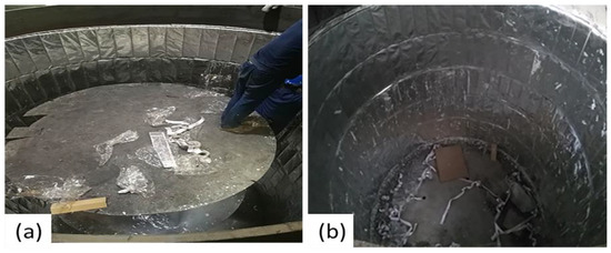
Figure 5.
(a) on-site construction operation and (b) construction completed.
2.2. Surface Temperature of Outer Steel Shell
2.2.1. Numerical simulation of Temperature Field of Steel Ladle Wall
(1). Establishment of Model
Without affecting the calculation results, in order to facilitate the establishment of the model, the following assumptions were proposed [24,25]: (1). The steel ladle trunnels, bottom breathable bricks and some driving devices structural reinforcements valves have little effect on the temperature field in the FEM of steel ladle wall, so these parts are omitted in the model; (2). The contact thermal resistance between the steel ladle insulating layer and the steel shell is negligible; (3). Due to the small slope angle of the steel ladle, the steel ladle can be regarded as a cylinder after removing the mechanical parts for loading and unloading around the steel ladle; (4). The temperature of molten steel is the same everywhere in the steel ladle; (5). Because the steel ladle has axially symmetrical geometry, a part of the steel ladle wall is taken for the FEM. The thermal conductivity equation is shown in Equation (1).
where λ is the thermal conductivity of the material, W/mK; T is the temperature, K; r is the normal distance, m; z is axial distance, m.
(2). Meshing
Figure 6 is a 2D model of the ladle wall which was designed by SOLIDWORKS 19.0, and imported into APDL of ANSYS 2020 R2 for processing. Because it’s a solid heat transfer model, plane 77 was chosen specifically for the heat transfer model which is a 2-dimensional 8-node thermal unit entity (each node has only one degree of freedom–temperature, and each element has a consistent temperature shape function), suitable for 2D steady-state or transient thermal analysis [26]. Therefore, the plane 77 was used in the ladle wall model to improve calculation accuracy. The steel ladle wall model was divided into 4450 units, and the total number of nodes is 11,236. The type of unit is quadrilateral. The advantage of this quadrilateral is that on the one hand it can reduce the amount of calculation. However, on the other hand, it doesn’t cause the mesh to be too distorted, resulting in inaccurate results.
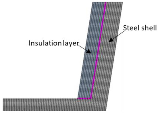
Figure 6.
Mesh division of steel ladle wall.
By comparing temperature difference of ladle wall with the counterparts calculated in the numerical model which contains a double quantity of mesh elements (including the test ladle wall model and the comparison ladle model), the difference in temperature difference remains constant, further refining of the mesh did not affect the results significantly, and the numerical computation independence on mesh is confirmed. Considering this result, the steel ladle wall model was divided into 4450 units, and the total number of nodes is 11,236. The type of unit is quadrilateral.
The temperature condition and convective heat transfer coefficient were used at the inner wall of thermal insulation material and the surface of OSS, the density, specific heat capacity, and thermal conductivity of materials were set, respectively. The calculation process adopted the stepped; the solution time was automatically set, and the steady-state solution was adopted.
(3). Initial and Boundary Conditions
According to steel ladle heat transfer form, in the process of heat transfer to the steel ladle wall, the inner wall of the steel ladle was set as the first type of boundary condition, as shown in Equation (2).
where r is the radius of steel ladle wall, m; and Tω is the temperature of the inner wall, °C.
The steel shell was set as the third type of boundary condition. As shown in Equation (3).
In the Equation (3), k is thermal conductivity along the normal direction, W/mK; Tf is the ambient temperature, °C, and h is the comprehensive convective heat transfer coefficient of air, W/m2K. T is the OSS temperature, °C.
Under the working condition of steel ladle containing molten steel, the working layer of the steel ladle directly contacts the high temperature molten steel of 1570–1630 °C. According to related references [27,28], the temperature of the inner wall of the insulating layer is between 700–900 °C, take the average value 800 °C (Tω) in this paper according to references [27,28], the OSS is in an external environment of 30 °C (Tf), and the heat transfer between OSS and the surrounding environment is convective heat exchange and radiation heat exchange. Generally, when the temperature exceeds 300 °C, the radiation heat transfer is strong, when the temperature is below 300 °C, the radiation heat transfer phenomenon is not obvious [29]. In the process of steel ladle turnaround, the surface temperatures of OSS are mainly 200–300 °C, the radiation heat transfer has little effect during the entire heat transfer process. Therefore, convective heat transfer and radiation heat transfer are converted into comprehensive convective heat transfer coefficient [30], so h is 8.1 W/mK. The physical parameters of the insulating layer are derived from the test data of Table 1.
2.2.2. The Surface Temperature of Outer Steel Shell Measurement
Many factors affect the temperature of the steel shell, especially the steel ladle used for converter steelmaking. The steel ladle is affected by its own conditions and external factors (such as the state of steel ladle, vacancy time, the tapping temperature of the molten steel, the type of alloy material, the added weight, and argon blowing stirring time). The temperature of the steel shell changes greatly, which is not easy to accurately compare. When the steel ladle is out-station of the LF, the molten steel temperature is uniform, sufficient and stable heat storage in each layer of the steel ladle wall, and the temperature fluctuation is small. After comprehensive thinking, the surface temperature data of the OSS after soft blowing at the out-station of the LF were collected.
Meanwhile, in order to reduce the influence of other production conditions on the measurement of surface temperature of OSS, it is stipulated that the steel ladle, steel type, temperature of molten steel, measuring temperature time and measuring temperature position are all measured under the same conditions.
In addition, during the use of steel ladle in a mid-maintenance period (the time from the steel ladle to the repair of the inner lining of the steel ladle is called a mid-maintenance period), the condition of steel ladle will gradually deteriorate due to the erosion of molten steel and other reasons, the heat storage of steel ladle wall is slightly different in a medium repair period, so in order to improve the measurement accuracy, the furnace age(the time interval between steel ladle passing through the same process each time is called one furnace age) was divided into early stage (1–50) and later stage(51–100). Details are as follows:
- (1)
- Steel ladle: steel ladle during the first mid-maintenance period.
- (2)
- Steel type: SPHC (The first S is the abbreviation of Steel, P is the abbreviation of Plate, H is the abbreviation of hot Heat, and C is the abbreviation of Commercial, which generally means hot-rolled Steel Plate and Steel belt).
- (3)
- Temperature of molten steel: 1580 ± 2 °C.
- (4)
- Temperature measuring tools: infrared temperature measuring thermometer.
- (5)
- Measuring temperature time: after soft blowing at the out-station of the LF.
- (6)
- Measuring temperature position: the same position of the steel ladle.
The temperature measuring tool uses a handheld infrared temperature measuring thermometer (Smart Sensor AS882) (Dongguan Wanchuang Electronic Products Co., Ltd., Dongguan, China). The temperature measuring range is from −18 °C to 1650 °C. The infrared temperature measuring thermometer and its working principle are shown in Figure 7.
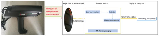
Figure 7.
Infrared temperature measuring thermometer and working principle.
Figure 8 shows on-site temperature measurement method. That is, within the effective distance, the infrared probe is aligned with the 0.01 m2 circle area marked of the surface OSS which is 1000 mm away from the upper stiffener and 800 mm from the right stiffener, and the temperature key is pressed for about 2 s to display the measured temperature. Measuring three times, then take the average of the three measured temperature values. A total of 70 steel ladles were measured (there are 36 test furnaces and 34 comparison furnaces).

Figure 8.
On-site temperature measurement.
2.3. Mathematical Model of Temperature Loss of Molten Steel
2.3.1. Heat Transfer Model
There are three basic ways of heat transfer: heat conduction, heat convection and heat radiation [31]. The heat transfer of high-temperature molten steel from the inside to the outside of the steel ladle is also divided into three parts. The first part is that the high-temperature molten steel heat enters the steel ladle wall through thermal conduction, among them, part of the heat is stored in the steel ladle wall, and the other part of the heat is radiated and convective through the OSS; the second part is the heat dissipation through the bottom of the steel ladle, the principle is the same as the first part; the third part is the heat dissipation of molten steel indirectly through the slag surface, which also includes three basic methods of heat conduction, heat convection and heat radiation at the same time. The proportion of heat dissipation in these three parts is shown in Figure 9 [32]. So the outward heat dissipation of the steel ladle becomes the calculation of the outward heat dissipation from the steel ladle wall.
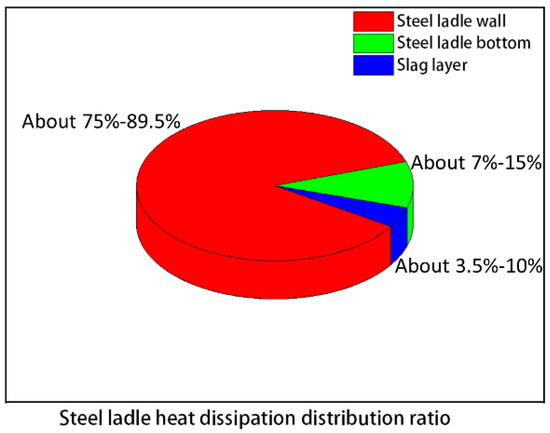
Figure 9.
Steel ladle heat dissipation distribution ratio.
According to the steel ladle heat transfer model, think of the steel ladle as a heat source with a constant surface temperature that dissipates heat to the outside. The difference of heat dissipation at different surface temperatures is only investigated here. In other words, the steel ladle and the molten steel are considered as a whole object. Since the steel ladle filled with molten steel has much more heat than its surface heat dissipation, the internal temperature of the steel ladle is much higher than the ambient temperature, and there is no forced cooling medium on the outer surface of the steel ladle. Therefore, the steel ladle can be used as a cylinder with a constant surface temperature. The amount of heat dissipation has nothing to do with the temperature of the molten steel, only related to factors such as steel ladle surface temperature and environmental conditions. Therefore, the formula can be used to calculate the change of molten steel temperature [33].
Heat loss of the steel ladle heat transfer is Equation (4).
where φ1 is the heat flow of thermal radiation of OSS, W; φ2 is the heat flow of thermal convection of the OSS, W.
The steel shell’s radiant heat flow can be described as follows.
where ε is the emissivity of steel shell; A is the OSS surface area, m2; σ is the Boltzmann constant (5.67 × 10⁻⁸ W/m2 K4); T1 is the surface temperature of OSS, K; T2 is the ambient temperature, K.
φ2 can be regarded as the convective heat transfer of a vertical cylinder, which is applicable to the convective heat transfer Equation (6).
where h is convective heat transfer coefficient the surface of OSS, W/m2k; A is the heat transfer surface area of OSS, m2; ΔT is the difference between the surface of OSS and the surrounding environment, K. h can be estimated as (7).
where is Nusselt Number, λ is the thermal conductivity of air, W/mK; is the height of the OSS, m. Nu can be estimated as (8).
where Gr is the Grashof Number, Pr is the Prandtl Number, C, n is the constant. Gr can be estimated as (9).
where g is the gravitational acceleration, m/s2; α is the volume expansion coefficient of air (the air in this paper is an ideal gas), the value is 3.676 × 10⁻³ [34]; ΔT is the difference between the surface of OSS and the surrounding environment, K; H is the height of steel ladle, m; v is the kinematic viscosity of air, m2/s.
2.3.2. Related Parameters of Model
According to the surface properties of different objects “Table of Emissivity of Various Surfaces” [35], the value of the steel shell ε is 0.80. According to Table 2, A is 44.71 m2.
Table 2.
Steel ladle related parameters.
Tqualitative temperature as the qualitative temperature of air, and its value is half the sum of ambient temperature and surface temperature of OSS. The values of v, λ, and Pr are shown in Table 3.
Table 3.
Physical parameters of air (303 K).
The value of C and n can be determined by the product of GrPr (see Table 4). When the minimum and maximum surface temperatures of the OSS are taken into GrPr, the value range of GrPr is shown in Formula (11). According to Formula (11) and Table 4, C is 0.135 and n is 1/3.
Table 4.
The relationship of GrPr to C and n.
2.3.3. Verification of the Model
Temperature data of molten steel are collected respectively: (1). Measure molten steel temperature data immediately after soft blowing of LF; (2). The temperature data of molten steel with an interval of 15 min from the last measurement. According to the temperature difference, the actual temperature drop rate of molten steel is calculated. Then, the results of the mathematical model are verified.
3. Results and Discussion
3.1. Surface Temperature of Outer Steel Shell
3.1.1. The Simulated Results
According to the simulation results, the steady-state temperature field distribution cloud map of the two different thermal insulation materials on the ladle wall is obtained (see Figure 10 and Figure 11). After the heat flux passes through the insulation layer, the following conclusions were obtained (see Table 5):
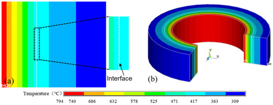
Figure 10.
(a) Comparison ladle wall slice and (b) expand 3D temperature field distribution cloud map.

Figure 11.
(a) Test ladle wall slice and (b) expand 3D temperature field distribution cloud map.
Table 5.
Simulation results of steel ladle wall.
- (1).
- The temperature of the comparative ladle’s OSS was 309 °C, and the temperature at the interface OCRIP and steel shell was 417 °C. It can be calculated that the thermal resistance rate of the SACIP is 47.9%.
- (2).
- The temperature of the test ladle OSS was 242 °C, and the temperature at the interface between SACIP and steel shell was 304 °C (see Figure 8). It can be calculated that the thermal resistance rate of the SACIP is 62.0%.
It can be seen that the thermal resistance of the SACIP was 14.1% higher than the OCRIP, and the surface temperature of OSS was 67 °C lower. The difference of the temperature of OSS between comparison ladle and test ladle is similar to that reported by Luo B [36], where they established that convective mechanisms were dominant in the heat transfer of temperature.
3.1.2. Measuring Result
Figure 12 shows the surface temperature of the OSS measured with an infrared temperature measuring thermometer. It can be seen that the surface average temperature of the test ladle’s OSS fluctuates between 233–260 °C, and the surface average temperature of the comparison ladle’s OSS fluctuates between 309–319 °C. In addition, the surface average temperature of the test ladle’s OSS is 59–73 °C lower than the comparison ladle when the steel ladle furnace age is 1–100.

Figure 12.
The surface average temperature of OSS measured.
3.1.3. Simulation Result Verification
Table 6 shows that the measurement results of the surface temperature OSS of test ladle and comparison ladle, and their average values range from 233–260 °C and 306–319 °C, respectively. The simulation results of test ladle and comparison ladle are 242 °C and 309 °C, respectively. The simulation results of the OSS surface temperature are all within the range of the measured temperature fluctuations, which verifies the validity of the finite element analysis of the ladle wall. This shows that the initial boundary temperature of the finite element was a reasonable choice at 800 °C, the selection of Plane 77 element is correct, also shows that the grid segmentation method, step solution setting is correct. However, Farrera-Buenrostro, J. E and others [37] pointed out that the temperature of the inner wall boundary of the insulation layer varies with factors such as the thermal conductivity of the insulation material and the state of molten steel. Therefore, this is the deficiency of the 2D heat transfer model. However, in this paper, on the basis of a large number of previous simulation results [38,39], the selected boundary temperature and model assumptions are feasible, and the experimental results also prove that the selected boundary conditions are within a reasonable range.
Table 6.
Surface temperature of OSS.
The results of measurement and simulation show that the insulation effect of the test ladle is better than for the comparison ladle; that is to say, SACIP has a better insulation effect than OCRIP. However, from the actual measurement results, the difference between the temperature of the test ladle wall in the early stage and the later stage is 27 °C, and the difference between the temperature of the comparison ladle wall is 13 °C, indicating that the temperature of the test ladle wall is greatly changed, and the specific reasons are still not clear. In subsequent tests, a large number of ladle wall temperatures should be measured to reduce the impact of less temperature data on the data. Meanwhile, more stringent temperature measurement measures should be established.
3.2. Temperature Loss of Molten Steel
3.2.1. Results of Mathematical Model Calculation
The heat flux of the comparison ladle and the test ladle φc ladle and φt ladle can be calculated by Formulas (4)–(9). According to (12), the temperature loss of molten steel can be calculated.
where: ∆T is the temperature difference of molten steel, °C; Q is the total heat transferred by OSS, J; m is the quality of molten steel, kg; CP is the specific heat capacity of molten steel, J/kg °C; t is the time of a furnace age under working conditions, s.
The drop rate of molten steel temperature can be calculated by Formula (13).
where: ∆V is the drop rate of steel molten temperature, °C/min; ∆T is the temperature difference of molten steel, °C; t is the time of a furnace age under working conditions, s.
Related parameter values are shown in Table 7.
Table 7.
Related parameter values for Formulas (12) and (13).
To sum up, in a furnace age, the test ladle saves 16.67 °C of molten steel temperature loss than the comparison ladle. The calculated results of the mathematical model are very close to the 18.8 °C drop of steel water temperature measured in Reference [40], the main reason for the difference of 2.13 °C is that the thermal conductivity of the insulation layer is 0.042 W/mK, ladle walls transfer heat outward quickly. The molten steel drop rate of the test ladle is 0.18 °C/min lower than the comparison ladle (see Appendix A for calculation process of temperature loss of molten steel).
3.2.2. Measuring Result
Table 8 shows the actual measured drop rate of steel molten temperature.
Table 8.
Actual molten steel temperature drop rate.
It can be seen from Table 8, when the steel ladle furnace age is 1–50, the temperature drop rates of comparison ladle and test ladle are 0.54 °C/min and 0.41 °C/min, respectively, the difference temperature drop rates of is 0.13 °C /min. when the steel ladle furnace age is 51–100; the temperature drop rates of comparison ladle and test ladle are 0.52 °C/min and 0.40 °C/min, respectively, the difference temperature drop rates of is 0.12 °C /min. Therefore, when the steel ladle furnace age is 1–100, the temperature drop rate of the test ladle can be 0.12–0.13 °C/min lower than comparison ladle.
According to the calculating model, the molten steel drop rate of the test ladle is 0.18 °C/min lower than the comparison ladle in a furnace age. The difference of molten steel temperature drop rate between test ladle and comparison ladle is 0.05–0.06 °C/min lower than obtained by calculation model. The reason is that the thermal insulation effect of the test ladle is better than comparison ladle, the heat loss of the ladle wall is small, the molten steel temperature is high, and the heat loss of the ladle slag layer and bottom is greater than the comparison ladle. However, in the mathematical calculation model, the heat loss of the slag layer and the ladle bottom is not considered, only the heat loss of ladle wall is considered [41].
3.3. Cost Comparison
In the production, the test ladle adopts the measure that the refining temperature of the LF is lowered by 16.67 °C than the comparison ladle. The relevant smelting parameters of the 130-ton LF are shown in Table 9 (CNY: Chinese Yuan).
Table 9.
The LF related parameters.
It can be seen from Table 9, When the LF out-station molten steel temperature of the test ladle is 16.67 °C lower than the comparison ladle, compared with the comparison ladle, the total cost of electricity and electrode saved by the test ladle is CNY 6.01/ton.
When the insulating layer is removed, the steel ladle furnace age is 600 furnaces, the steel ladle volume is 130 tons on average, the price of the SACIP is CNY 1200/m2, the steel ladle insulating layer is double layer, and the usable area is 89.4 m2, Therefore, it is concluded that the cost of using the SACIP in the test ladle is CNY 1.38/ton.
According to the factory’s annual production cost data, the cost of using the OCRIP for the comparison ladle is CNY 0.52/ton. Therefore, the cost of the insulating layer of the test ladle exceeds the cost of the comparison ladle by CNY 0.86/ton. The cost of the test ladle for saving electrodes and electricity is CNY 6.01/ton, so the total cost savings of the test ladle is CNY 5.15/ton compared to the comparison ladle.
4. Conclusions
To study the application effect of steel ladle insulation materials, a new research method is designed in this paper. The main conclusions can be drawn as follows:
- The actual measurement of the surface OSS temperature shows that the surface OSS average temperature of the test ladle is 59–73 °C lower than the comparison OSS. According to the simulation results of the steel ladle wall, the surface OSS temperature of the test ladle is 67 °C lower than that the comparison OSS. The simulation results are within the range of the average temperature of the actual measured surface OSS, which proves the accuracy of the FEM and the selection of related parameters.
- According to the calculation model of molten steel temperature loss, compared with the comparison ladle, the test ladle in a furnace age, can save the temperature loss of molten steel 16.67 °C, and reduce the temperature drop rate of molten steel by 0.18 °C/min. In addition, when the steel ladle furnace age is 1–100, the temperature drop rate of the test ladle can be 0.12–0.13 °C/min lower than comparison ladle. Although the difference of molten steel temperature drop rate between test ladle and comparison ladle is 0.05–0.06 °C/min lower than obtained by calculation model, the Boltzmann mathematical model is still valid in evaluating the effect of the insulation layer and relevant parameters and solutions are correct.
- In the LF, by reducing the temperature of molten steel in the test ladle by 16.67 °C, the cost of a test ladle can be reduced by CNY 5.15/ton compared with the comparison ladle. Using silica aerogel composite insulation panels on a steel ladle plays a very positive role in reducing production costs and energy consumption.
- The new method designed in this paper to calculate the thermal insulation effect of steel ladle insulation layers is feasible. The ladle wall temperature is obtained by finite element model and experiment, then the heat emission from the ladle wall is calculated by the Boltzmann equation according to ladle wall temperature, and the temperature loss of molten steel is calculated inversely according to the heat emission.
- In a furnace age, the surface temperature of OSS of the test ladle measured fluctuated by a larger amount than did the comparison ladle. The specific reason for this is still unclear, and further study is required.
Author Contributions
L.Z. (Limin Zhang): Writing—original draft, Writing—review and editing, Conduct experiment, Data, Graphics; L.Z. (Liguang Zhu): Project administration, Methodolog, Review, Funding, Goals and Aims; C.Z.: Contacting with the plant, Formal Analysis; P.X.: Contacting with the plant; Z.W.: Assist in translation, Formal Analysis; Z.L.: Visualization, review. All authors have read and agreed to the published version of the manuscript.
Funding
This work was funded by the Nature Science Foundations of Hebei Grant Nos. CXZZBS2020130, E2020209005, National Natural Science Foundation of China (51904107), Tangshan Talent Subsidy project(A202010004).
Institutional Review Board Statement
Not applicable.
Informed Consent Statement
Not applicable.
Data Availability Statement
No new data were created or analyzed in this study. Data sharing is not applicable to this article.
Conflicts of Interest
There is no interest conflict with others.
Nomenclature
| Abbreviation | Description | Unit |
| CP | Special heat capacity | J/kgk |
| T | Temperature | °C |
| t | Time | s |
| r | Ladle wall radius | m |
| z | Ladle wall thickness | m |
| k | Thermal conductivity | W/mK |
| h | convective heat transfer coefficient | W/m2K |
| A | Area | m2 |
| Nu | Nusselt Number | dimensionless |
| D | Diameter | m |
| H | Height | m |
| Gr | Grashof Number | dimensionless |
| Pr | Prandtl Number | dimensionless |
| C | Constant determined by experiment | dimensionless |
| n | Constant determined by experiment | dimensionless |
| g | Gravitational acceleration | m/s2 |
| Heat | J | |
| m | Quality | kg |
| Greek Symbols | ||
| ρ | Density | kg/m3 |
| λ | Thermal conductivity | W/mK |
| φ | Heat flow | W |
| ε | Emissivity | dimensionless |
| σ | Boltzmann constant | W/m2 K4 |
| α | Volume expansion coefficient | dimensionless |
| ν | Kinematic viscosity | m2/s |
Appendix A. Mathematical Model Calculation Process of Temperature Loss of Molten Steel
The steel ladle furnace age is 1–50, suppose: the radiation heat dissipation of the test OSS is φt1, W; the convective heat transfer is φt2, W; the radiation heat dissipation of the comparative OSS is φc1, W; the convective heat transfer is φc2, W; φC ladle(1–50) is the sum of φc1 and φc2, W; φT ladle(1–50) is the sum of φt1 and φt2, W.
According to the Formula (A1):
Parameter value in the Formula (A1): ε = 0.8; A = 44.71 m2; σ = 5.67 × 10⁻⁸ W/m2 K4; the values of T1 and T2 are shown in Table A1.
Calculated:
Table A1.
Surface temperature of OSS after the LF out-station.
Table A1.
Surface temperature of OSS after the LF out-station.
| Steel Ladle Condition | Surface Temperature of OSS (+273 K) | ||
|---|---|---|---|
| Measurement Result | Simulation Result | ||
| Early Stage (1–50 Furnace Age) | Later Stage (51–100 Furnace Age) | ||
| Test ladle | 233 | 260 | 242 |
| Comparison ladle | 306 | 319 | 309 |
When the steel ladle furnace age is 51–100, suppose: the heat dissipation of the test OSS is φt3, W; the convective heat transfer is φt4, W; The radiation heat dissipation of the comparative shell is φc3, W; the convective heat transfer is φc4, W; φC ladle(51–100) is the sum of φc3 and φc4, W; φT ladle(51–100) is the sum of φt3 and φt4, W.
According to the Formulas (A2)–(A5):
Parameter value in the Formulas (A2)–(A5) are shown in Section 2.3 of the paper.
Calculated:
φTotal is the difference between the heat dissipation of the comparative steel ladle and the test steel ladle. Therefore, the mid-repair period of each steel ladle age (the steel ladle furnace age is 1–100, the steel ladle turnaround once). The value of φ is as follows.
According to the heat dissipation Formula (A6).
where: ∆T is the decreasing temperature of molten steel due to the heat dissipation by the steel ladle shell, °C; Q is the heat dissipation of the OSS, J; m is the quality of molten steel, kg; CP is the specific heat capacity of molten steel, J/kg °C; t is the steel ladle turnaround once time under working conditions, s.
Related parameters of Formula (A6) are shown in Table A2.
Table A2.
Related parameter values for Formula (A6).
Table A2.
Related parameter values for Formula (A6).
| Parameter | Value |
|---|---|
| φ | 0.717 × 10⁶ W |
| m | 1.30 × 10⁵ kg |
| t | 5400 s |
| CP (1600 °C) | 0.837 × 10³ J/kg°C |
The drop rate of molten steel temperature can be calculated by Formula (A7).
where: ∆V is the drop rate of steel water temperature, °C/min; ∆T is the temperature difference of molten steel, 16.37 °C; t is the steel ladle turnaround once time under working conditions, 5400 s.
To sum up,
References
- Glaser, M.; Gornerup, M.; Du, S.C. Fluid flow and heat transfer in the ladle during teeming. Steel Res. Int. 2011, 82, 827–835. [Google Scholar] [CrossRef]
- Wang, Y.; Ai, X.G.; Liu, F.; Zhong, W.M.; Huang, R.H. Physical simulation of symmetric alternating bottom blowing mixing behavior in double orifice ladle. China Metall. 2017, 27, 18–21. [Google Scholar]
- Glaser, B.; GorRnerup, M.; Du, S.C. Thermal modelling of the ladle preheating process. Steel Res. Int. 2011, 82, 1425–1434. [Google Scholar] [CrossRef]
- Wang, S.S.; Guo, X.C.; Jiang, W.H.; Li, Q.; Zhang, F. Numerical simulation and field practice of flow field in 100 t bottom blown argon ladle. China Metall. 2018, 28, 51–55. [Google Scholar]
- Liu, Z.Z.; Guo, H.Z. Development and present situation concering heat transfer research of ladle. Iron Steel Res. 2007, 2, 59–63. [Google Scholar]
- Dong, P.L. Physical simulation of 210 t ladle bottom blowing process optimization. Iron Steel 2016, 51, 41–45. [Google Scholar]
- Zhang, Y.Y.; Cui, K.K.; Fu, T.; Wang, J.; Shen, F.Q.; Zhang, X.; Yu, L.H. Formation of MoSi2 and Si/MoSi2 coatings on TZM (Mo-0.5Ti-0.1Zr-0.02C) alloy by hot dip silicon-plating method. Ceram. Int. 2021, 47, 23053–23065. [Google Scholar] [CrossRef]
- Wohrmeyer, C.; Gao, S.M.; Ping, Z.F.; Parr, C. Corrosion mechanism of MgO-CMA-C ladle brick with high service life. Steel Res. Int. 2019, 91, 1900436. [Google Scholar] [CrossRef]
- Chang, W.J. Influence Analysis and Life Prediction of New Structure Ladle with Super-Insulation and Lightweight. Master’s Thesis, Wuhan University of Science and Technology, Wuhan, China, 1 June 2018. [Google Scholar]
- He, W.X. Development on Longevity and High Efficient Thermal Insulation Technique of Ladle with Thin Layer and Its Application. Master’s Thesis, Chongqing University, Chongqing, China, 1 June 2007. [Google Scholar]
- Onyeaju, M.C.; Osarolube, E.; Chukwuocha, E.O.; Ekuma, C.E.; Omasheye, G. Comparison of the thermal properties of asbestos and polyvinylchloride (PVC) ceiling sheets. Mater. Sci. Appl. 2012, 3, 240–244. [Google Scholar] [CrossRef][Green Version]
- Khalaf, F.M. Using crushed clay brick as coarse aggregate in concrete. J. Mater. Civ. Eng. 2006, 18, 518–526. [Google Scholar] [CrossRef]
- Hall, C.; Wilson, M.A.; Hoff, W.D. Kinetics of long-term moisture expansion in fired-clay brick. J. Am. Ceram. Soc. 2011, 94, 3651–3654. [Google Scholar] [CrossRef]
- Zhang, Y.Y.; Fu, T.; Cui, K.K.; Shen, F.Q.; Wang, J.; Yu, L.H.; Mao, H.B. Evolution of surface morphology, roughness and texture of tungsten disilicide coatings on tungsten substrate. Vacuum 2021, 191, 110297. [Google Scholar] [CrossRef]
- Cui, K.; Zhang, Y.; Fu, T.; Hussain, S.; Saad Algarni, T.; Wang, J.; Zhang, X.; Ali, S. Effects of Cr2O3 content on microstructure and mechanical properties of Al2O3 matrix composites. Coatings 2021, 11, 234. [Google Scholar] [CrossRef]
- Gruber, D.; Harmuth, H. Thermomechanical behavior of steel ladle linings and the influence of insulations. Steel Res. Int. 2014, 84, 512–518. [Google Scholar] [CrossRef]
- Jia, C.J.; Song, D.J.; Sun, J.B. Research on the application of new type thermal insulation material for casting ladle. Foundry Equip. Technol. 2018, 1, 42–44. [Google Scholar]
- Sun, Y.; Zhao, S.H.; Li, Z.S. Development of aerogel insulation board and its thermal insulation effect in ladle. Tianjin Sci. Technol. 2018, 8, 59–61. [Google Scholar]
- Lv, W.; Mao, Z.; Yuan, P.; Jia, M. Pruned bagging aggregated hybrid prediction models for forecasting the steel temperature in ladle furnace. Steel Res. Int. 2014, 85, 405–414. [Google Scholar] [CrossRef]
- Romao, I.; Nduagu, E.; Fagerlund, J.; Gando-Ferreira, L.M.; Zevenhoven, R. CO2 fixation using magnesium silicate minerals. Part 2: Energy efficiency and integration with iron-and steelmaking. Energy 2012, 41, 203–211. [Google Scholar] [CrossRef]
- Taddeo, L.; Gascoin, N.; Fedioun, I.; Chetehouna, K.; Lamoot, L.; Fau, G. Dimensioning of automated regenerative cooling: Setting of high-end experiment. Aerospace Sci. Tech. 2015, 43, 350–359. [Google Scholar] [CrossRef]
- Cui, Z.; Zhang, J.; Wu, D. Hybrid many-objective particle swarm optimization algorithm for green coal production problem. Inf. Sci. 2020, 518, 256–271. [Google Scholar] [CrossRef]
- Hu, J.; Sun, Y.; Li, G.; Jiang, G.; Tao, B. Probability analysis for grasp planning facing the field of medical robotics. Measurement 2019, 141, 227–234. [Google Scholar] [CrossRef]
- Wu, X.H.; Meng, X.W.; Chen, L.; Zheng, C.L. Numerical simulation of ladle temperature field under the working conditions of ladle baking and steel holding. Electron. Qual. 2018, 376, 84–86. [Google Scholar]
- Li, H.C.; Huang, S.M.; Chen, X.Y. Simulation research of ladle temperature field and stress field based on ANSYS. Equip. Manuf. Technol. 2007, 40, 35–37. [Google Scholar]
- Warzecha, M.; Jowsa, J.; Warzecha, P.; Pfeifer, H. Numerical and experimental investigations of steel mixing time in a 130 t ladle. Steel Res. Int. 2008, 79, 852–857. [Google Scholar] [CrossRef]
- Chen, Y.C.; Bao, Y.; Wang, M.; Zhao, L.; Peng, Z. A mathematical model for the dynamic desulfurization process of ultra-low-sulfur steel in the LF refining process. Metall. Res. Technol. 2014, 111, 37–43. [Google Scholar] [CrossRef]
- Wu, Y.F.; He, D.F.; Xu, A.J.; Tian, N.Y. Numerical simulation and optimization of temperature field in the baking ladle. J. Iron Steel Res. 2012, 21, 21–24. [Google Scholar]
- Li, Q. Study on Heat Transfer Model of Ladle in Steelmaking and Continuous Casting Process. Master’s Thesis, Northeastern University, Shenyang, China, 7 July 2010. [Google Scholar]
- Wu, T.; Chen, M.; Zhang, L.; Xu, X.; Liu, Y.; Yan, J.; Wang, W.; Gao, J. Three-dimensional graphene-based aerogels prepared by a self-assembly process and its excellent catalytic and absorbing performance. J. Mater. Chem. A 2013, 1, 7612–7621. [Google Scholar] [CrossRef]
- Li, D.Y. Physical and mathematical model of heat transfer in plasma ladle furnace. Iron Steel 1997, 3, 16–18. [Google Scholar]
- Li, Q.; Wei, D.Y.; Yang, C. Calculation and analysis of steady-state heat transfer of 150-Ton ladle wall. Metall. Ser. 2015, 1, 8–11. [Google Scholar]
- Solorio-Diaz, G.; Davila-Morales, R.; Jose, B.S.; Vergara-Hernández, H.J.; Ramos-Banderas, A.; Galvan, S.R. Numerical modelling of dissipation phenomena in a new ladle shroud for fluidynamic control and its effect on inclusions removal in a slab tundish. Steel Res. Int. 2014, 85, 863–874. [Google Scholar] [CrossRef]
- Zhou, Y.; Dong, Y.C.; Wang, H.C.; Wang, S.J.; Liu, Y.B. Mathematical simulation of flow phenomena in CAS-OB refining ladle. J. Iron Steel Res. 2003, 10, 8–12. [Google Scholar]
- Singham, J.R. Tables of emissivity of surfaces. Int. J. Heat Mass Transf. 1962, 5, 67–76. [Google Scholar] [CrossRef]
- Luo, B.; Li, G.; Kong, J.; Jiang, G.; Sun, Y.; Liu, Z.; Chang, W.; Liu, H. Simulation analysis of temperature field and its influence factors of the new structure ladle. Appl. Math. Inf. Sci. 2017, 11, 589–599. [Google Scholar] [CrossRef]
- Farrera-Buenrostro, J.E.; Hernández-Bocanegra, C.A.; Ramos-Banderas, J.A.; Torres-Alonso, E.; López-Granados, N.M.; Ramírez-Argáez, M.A. Analysis of temperature losses of the liquid steel in a ladle furnace during desulfurization stage. Trans. Indian Inst. Met. 2019, 11, 22–23. [Google Scholar] [CrossRef]
- Lu, B.; Meng, X.; Zhu, M. Numerical analysis for the heat transfer behavior of steel ladle as the thermoelectric waste-heat source—ScienceDirect. Catal. Today 2018, 318, 180–190. [Google Scholar] [CrossRef]
- Prabhakaran, S.; Maboob, S.A. Numerical analysis and experimental investigation on behavior of cold-formed steel castellated beam with diamond castellation. Int. J. Steel Struct. 2021, 21, 1082–1091. [Google Scholar] [CrossRef]
- Xia, J.L.; Ahokainen, T. Transient flow and heat transfer in a steelmaking ladle during the holding period. Met. Mater. Trans. B 2001, 32, 733–741. [Google Scholar] [CrossRef]
- Urióstegui-Hernández, A.; Garnica-González, P.; Ángel Ramos-Banderas, J.; Hernández-Bocanegra, C.A.; Solorio-Díaz, G. Multiphasic study of fluid-dynamics and the thermal behavior of a steel ladle during bottom gas injection using the eulerian model. Metals 2021, 11, 1082. [Google Scholar] [CrossRef]


Publisher’s Note: MDPI stays neutral with regard to jurisdictional claims in published maps and institutional affiliations. |
© 2021 by the authors. Licensee MDPI, Basel, Switzerland. This article is an open access article distributed under the terms and conditions of the Creative Commons Attribution (CC BY) license (https://creativecommons.org/licenses/by/4.0/).