Article

Influence of Carbon Nanowalls Interlayer on Copper Deposition

1
Faculty of Applied Chemistry and Materials Science, Politehnica University of Bucharest, 1-7 Polizu Street, 011061 Bucharest, Romania
2
National Institute for Laser, Plasma and Radiation Physics, 409 Atomistilor Street, 077125 Bucharest, Romania
3
Research Institute—ICPE, Splaiul Unirii 313, 030138 Bucharest, Romania
*
Author to whom correspondence should be addressed.
Coatings 2021, 11(11), 1395; https://doi.org/10.3390/coatings11111395
Submission received: 23 September 2021 / Revised: 1 November 2021 / Accepted: 11 November 2021 / Published: 16 November 2021

Abstract

:
This research deals with the deposition of copper on a steel substrate. Two different methods were investigated: electrochemical and magnetron sputtering. The deposition parameters were optimized to obtain a coating layer with uniform granular structure and good adhesion to the substrate. As a novelty, carbon nanowalls (CNW) were used as reinforcement in copper coatings on the steel surface. The morphology of the coatings, adhesion and Vickers microhardness were performed to emphasize the CNW influence on the coating properties. Open circuit potential and Tafel analysis were used for electrochemical characterization. These kinds of CNW-copper composite with improved hardness and adhesion and surface electrical resistance around 1 Ω·cm could have miscellaneous applications in different domains such as aerospace, electronics, automotive and power-generation.

1. Introduction

Steel is a metallic material with many applications in different industries as a structural material [1], for medical applications [2], for electronics or electrodes in energy sources [3,4] and also in daily life [5,6,7]. In many of these applications, it is necessary to modify the steel surface to improve the surface properties [1,8].
Copper coated steel has undergone a growing demand in aerospace systems such as space stations and satellites, as well as electronics, automotive, and power-generation industries [9,10]. A bimetallic copper–steel receiver was proposed for use in the direct steam generation (DSG) [11]. Copper-coated steel was used for high level nuclear waste containers [12,13]. Stainless steel mesh was coated with copper in anhydrous ethaline ionic liquid solution and used as a negative electrode in flexible energy storage devices [3]. Other industrial applications of copper coated steel include: a reactor or a heat exchanger construction, as implant coating, corrosion protection coating, oil/water separation, and coated electrodes for benzene removal from an air flow. 316 H stainless steel electroplated with copper coatings was used in a molten salt reactor [14]. Carbon steel coated with copper for furnace brazing, due to the good thermal conductivity of copper, could be used as a structural material in a heat exchanger [15]. An innovative surface coating made of zein, bioactive glass, and copper containing bioactive glass was used as an antibacterial, pro-angiogenic and pro-osteointegrative coating on stainless steel implants [16]. 304 stainless steel electrochemically coated with copper—polypyrrole (Cu–PPy) in a single step showed corrosion protection ability by decreasing the mobility of the corrosive solution within the pores of the coatings [17]. A mechanically durable and chemically stable Cu coated stainless steel mesh had excellent self-cleaning and oil–water separation efficiency [18]. Nano-hill Cu-coated stainless steel electrodes were used as discharge electrodes in a positive discharge non-thermal plasma reactor for benzene removal [19].
Copper coatings proved to bring an improvement to the substrate. For example, WC−Cu composite coating prepared by electroplating exhibited high hardness (HV 221) and high electrical conductivity [20]. In the case of 316 stainless steel coated with Cu, using wire-arc spraying, a sample having 150 microns thickness was found to have the least adhesion strength, hardness near the interface of 130 HV, Young’s modulus of 60 GPa and yield strength of 94 MPa [21]. Copper coatings deposited by low-pressure cold spraying on aluminum alloy, having thickness of about 200 μm, showed increased electrical conductivity and increased hardness in the case of the coating sprayed with composite E-Cu+Al2O3 powder. The corrosion potential was higher than that of the substrate material [22]. Corten A588 steel plate electroplated with a 10.17 µm Cu coating showed an increased hardness compared to the substrate, exhibited a higher corrosion potential (Ecorr), a lower corrosion current density (Icorr) and a higher charge transfer resistance value of compared to the substrate (due to the formation of copper oxide amidst coating-solution interfaces) [23]. A copper coated steel plate immersed in a silane solution and heat treated had a satisfactory resistance to acids and bases and possessed superhydrophobic properties with a contact angle of 166° [24]. Metallic copper coated onto the surface of X80 pipeline having hierarchical structure showed excellent repellency toward olive oil, glycerol, distilled water, and ethylene glycol, and was thermally and mechanically stable when subjected to ultraviolet (UV) light, an acid-base medium, high temperature, and abrasion [25].
Depending on the purpose of the copper plating, various electrolytes containing copper ions are used for copper electrodeposition, cyanide bath being the one most often used [26]. Copper metallic coating is not only used as a protection against corrosion, but also because of its excellent electrical and thermal conductivity; it can be easily fabricated, has a low cost [27] and also has antibacterial properties [2]. Using reinforcements, a composite coating with improved properties can be obtained [28]. These properties depend to a large extent on the nature and content of the reinforcement used. Copper composite coatings based on different carbon structures were studied: carbon nanotubes [29,30], graphene oxide [28], and carbon nanofibers [31,32]. Carbon nanotubes (CNT) with a few micrometers in length and diameters on the order of nanometers [33] can be used as reinforcements in composite coatings, because they have unique mechanical, thermal and electrical properties [34]. Recently, electrodeposition of copper on planar CNT sheets was successfully shown and both mechanical and electrical properties were enhanced [34]. In addition, copper composite coatings with other carbon structures—graphene or reduced graphene oxide, showed improved mechanical properties (wear resistance, Vickers hardness), and thermal conductivity [28]. Carbon fibers reinforced in a copper metal matrix also offers excellent characteristics, namely good self-lubrication, low thermal expansion, low thermal conductivity, good wear resistance and high mechanical strength [35]
Other carbon nanostructures, carbon nanowalls (CNW), were also obtained and presented in our recent publications for electronics (micro-supercapacitors) [36] or bio applications (to mediate biological cells interaction with oxidized silicon substrate) [37,38]. These can be described as networks of interconnected carbon walls with a few to tens of nanometers thickness, grown vertically on a substrate [39]. Davami and co-workers showed increased mechanical properties for CNW grown on copper substrate coated with alumina (Al2O3) [40]. We consider that these carbon nanostructures could also have the potential to be used as reinforcements in copper coatings.
Considering improved mechanical properties (wear resistance, Vickers hardness) and improved electrical properties obtained in the case of carbon nanostructures/copper coatings described in the literature [28,33,34,35], the purpose of this study was to use CNW as an intermediate layer for the copper deposition on steel surface and to assess their influence on coating properties. Such structure may find application in various domains, for example, improvements of the mechanical properties of the fragile CNW layers by their reinforcement [40], obtaining a low friction coefficient and less wear surfaces [41], and improvement of heat transfer, allowing superior thermal dissipation.
The influence of these carbon nanostructures on copper deposition and coating properties were studied. Two copper coating deposition methods were used: electroplating and magnetron sputtering. In both deposition techniques, by electrodeposition and plasma magnetron sputtering, the important effect of the CNW interlayer on the morphology was observed, improvement of adherence on CNW on metal, and the promoting of the formation of nucleation sites for electrodeposition in order to obtain hybrid metal carbon nanostructured architectures.

2. Materials and Methods

2.1. Experimental

The tests were performed on steel (OL) samples (K455, weight percentage as follows: C 0.60%, Si 0.69%, Mn 0.34%, Cr 1.19%; V 0.18%, W 2%, P 0.015%, S 0.012%; Fe 94.97%, (2 mm thick) available from Bohler. Samples with a 9.6 cm2 area were cut for experiments. The surfaces of the samples were prepared by an etching process in H2SO4 (Sigma Aldrich, St. Louis, MO, USA) for 5 min, then the samples were slide grinded using centrifugal force to obtain a homogeneous surface using a Spaleck Z11 (Spaleck Oberflächentechnik GmbH & Co. KG, Bocholt and Germany) with stainless steel media. Subsequently, polished samples were degreased in ethanol and acetone (Sigma Aldrich, St. Luis, USA) in the ultrasound bath for 5 min.
Other reagents used were: copper cyanide (CuCN, Sigma Aldrich) and potassium cyanide (KCN, Sigma Aldrich), NaCl (Sigma Aldrich) aqueous solution 0.9%. All the chemicals were used directly, without any further purification. Aqueous solutions were prepared using purified water obtained from a Millipore Direct-Q UV3 water purification system.

2.2. Carbon Nanowalls (CNW) Deposition

Carbon nanowalls deposits were synthesized by a plasma enhanced chemical vapor deposition procedure described in detail elsewhere [42]. The experimental conditions used in this work were as follows: gas mixtures of Ar/H2/C2H2 in ratio 1400 sccm/25 sccm/2 sccm, pressure 1.3 mBar, RF Power: 300 W, substrate temperature 700 °C for 60 min deposition time. To ensure a good adhesion of CNW layers to the steel substrate, in the first step, the substrate was submitted to Ar/H2 plasma (1400 sccm/25 sccm) pre-treatment for 10 min at 700 °C.
Some samples of K455 steel coated with CNW were subjected to thermal treatment in a LabTech furnace (Daihan Labtech, Gyeonggi-do, Korea), at 100 °C for 2 h for oxidation and to make those samples hydrophilic [39].

2.3. Copper Coatings

Copper depositions processes on K455 steel samples were performed by two different methods: electrochemical deposition and magnetron sputtering deposition.
The electrochemical deposition was performed from an alkaline solution containing CuCN 60 g/L and KCN 30 g/L using an Autolab 302 N potentiostat-galvanostat (Metrohm, Utrecht, The Netherlands). An electrochemical cell formed by a 3-electrode system was carried out (as a working electrode prepared K455 steel sample was used, as a reference electrode Ag/AgCl, 3M KCl from Metrohm Utrecht, BV was used and a pure copper plate was used as the auxiliary electrode). The working temperature used was 50 °C, maintained using a C-MAG HS 7 hotplate (IKA, Staufen, Germany). Electrodeposition experiments were performed at different constant voltages: 0.7, 1, 1.5 and 2 V. In every case, the process took 20 min. These experiments served to select the voltage which gave the best results. Pulsed electrodepositions were also performed. The applied signal was applied according to the scheme presented in Figure 1. In all cases:
  • E1 was −2 V and t1 2 s, to initiate the copper nucleation;
  • E2 was the open circuit potential;
  • E3 was −1 V and t3 5 s.
The number of repeating times, n, was 100 or 150 pulses.
Copper coating was also prepared by magnetron sputtering using a pure copper target (2-inch Cu 99.999% target from Kurt J. Lesker Company, (UK), in a separate setup [43]. The experimental conditions used were RF power 250 W, distance between magnetron and sample 5 cm, working pressure 5.6 × 10⁻³ mBar, Ar flow: 50 sccm, Time: 120 s, rotation speed: 1 rot/s.

2.4. Samples Characterizations

The samples’ surface morphology was observed using scanning electron microscopy (SEM). Two microscopes were used: Apreo S (Thermo Fisher Scientific, Hillsborough, CA, USA) and Quanta 650 FEG (Thermo Fisher Scientific, Hillsborough, CA, USA), with high resolution scanning and ESEM technology.
Fourier Transformed Infrared Spectrum (FTIR) was recorded using a Perkin Elmer Spectrum 100 FT-IR (Perkin Elmer, Waltham, MA, USA) acquired in ATR mode. Recordings were performed between 4000 and 600 cm−1, using four consecutive scans. Spectra recorded with 4 cm−1 resolution were processed with the corresponding software, making background correction and automatic smoothing.
Contact angle values were recorded using a Contact Angle Meter—CAM 100 (KSV Instruments Ltd., Helsinki, Finland) using the sessile drop method. With a Hamilton glass syringe, distilled water droplets were put on the sample surface and corresponding contact angles were recorded. Contact angles’ measurements were performed in normal conditions (room temperature and light/humidity). At least three different measurements were made on a sample and the mean value was given. Using an Excel program, the standard deviation was determined.
Vickers hardness tests were performed with a Wilson UH250 Universal Hardness Tester (Buehler, Bluff, IL, USA) equipped with a pyramid type penetrator with a square diamond base top angle of 136°. For each sample, the test was performed on at least 3 different areas and HV5 was used (5 kg weight force). The depth of penetration was between 29 and 34 µm. That meant that the indenter penetration was greater than the film thickness and it penetrated to the substrate.
Adhesion tests were performed according to ASTM D3359—Standard Test Methods for Measuring Adhesion by Tape Test—Test Method B—Cross Cut Tape Test [44]. Cross cut tests were performed using a special deice sharp razor blade device as the cutting tool (with the cutting-edge angle between 15 and 30°) that made several cuts at once to obtain a grid like pattern. The tape was applied and removed 2 times for each sample. After this experiment was performed, the area where the tape was applied and removed was examined to verify if there were any peel-offs in the coated surface. Adhesion results were rated in accordance with the following ASTM D3359 Standard scale:
  • 5B—the edges of the cuts are completely smooth; none of the squares of the lattice is detached;
  • 4B—small flakes of the coating are detached at intersections; less than 5% of the area is affected;
  • 3B—small flakes of the coating are detached along the edges and at the intersections of the cuts. The area affected is 5 to 15% of the lattice;
  • 2B—the coating has flaked along the edges and on parts of the squares. The area affected is 15 to 35% of the lattice;
  • 1B—the coating has flaked along the edges of cuts in large ribbons and whole squares have detached. The area affected is 35 to 65% of the lattice;
  • 0B—flaking and detachment is worse than Grade 1.
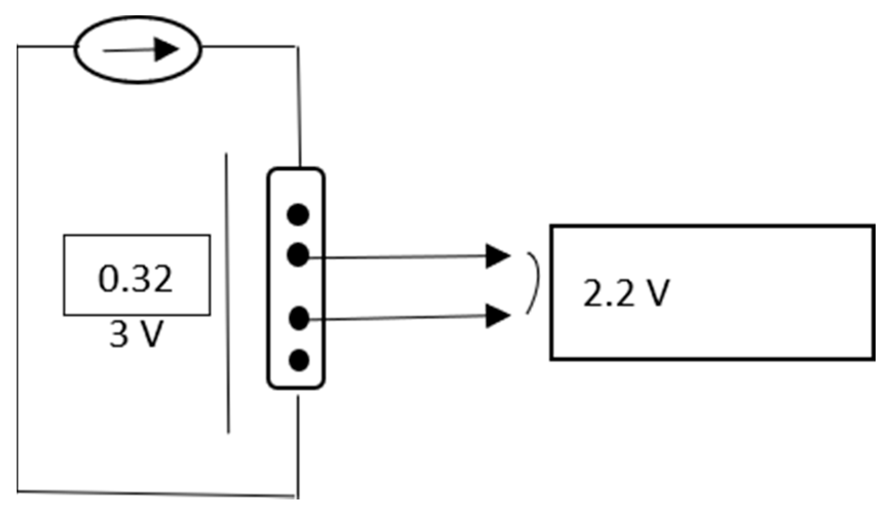
The resistivity was measured by the four-point probe method, and in its calculation the intermediate voltage between the two points was used. Electrical measurements were performed by using a Keithley 2400 source-meter and a Keithley 6517a electrometer assisted by a computer, in the room temperature range allowed by our experimental setup (Figure 2). R (resistivity) = U I · d (experimental), where we have d = 1 cm, U (V) = 0.323 V and I (mA) = 10 mA. The resistivity measurement was made in four points, and in its calculation the intermediate voltage between the two points was used.
Electrochemical characterizations were also performed with the Autolab 302 N potentiostat-galvanostat (Metrohm, Utrecht, The Netherlands) with Nova 1.11 software, at room temperature. All measurements were performed in aqueous NaCl 0.9%, at room temperature and light. The steel or steel coated samples were used as the working electrode, a platinum road (Metrohm, Utrecht, BV) was used as the counter electrode and Ag/AgCl 3 M KCl glass electrode was used as the reference. Working electrode samples were mounted in a home-made plexiglass cell with an O ring, in order to have the same surface exposed to the electrolyte—0.5 cm2. Open circuit potential (OCP) measurements were performed for 1800 s. Tafel Plots were recorded between ±250 mV from the open circuit potential value, with 2 mV/s scan rate. Samples were let immersed over a total of 192 h and recordings were made at the initial time and once every 24 h.

3. Results and Discussion

3.1. CNW Deposition on K455 Steel

A sample coated with carbon nanowalls was prepared on K455 steel (OL) by plasma deposition in experimental conditions optimized in previous studies [36,37,38]. SEM images corresponding to this sample are presented in Figure 3a–c, at different magnifications, and the sample was named OL/CNW. In Figure 3a, at lower magnification, it is visible that the deposited layer is uniformly distributed on the steel surface. The obtained structure is porous, Figure 3b,c having long, interconnected walls with sharp edges, grown vertically on the steel substrate. The substrate surface area was much increased by these nanostructure depositions. Carbon nanowalls structures, with their high surface area, could be good candidates to incorporate copper and can be used as the interlayer to obtain composite copper coatings on stainless steel. The CNW high surface area is often reported in literature (according to the BET data, the samples demonstrated a specific surface area of about 1000 m2/g) [45].
The thickness of the CNW layer was about 7 micrometers. The thickness was estimated from a cross-section of the SEM images on layers deposited onto silicon under similar conditions [46].
The ATR FT-IR spectra of the coatings are visible in Figure 3d. Characteristic peaks are detailed in the insets. The peaks corresponding to carbon nano-walls are visible: at 970 cm−1 for C-H scissoring, at 3010 cm−1 assigned to C-H stretching, CH3 stretching identified at 2862 and 2949 cm−1; and at 2829 and 2903 cm−1 CH2 stretchings are visible. Other peaks are C-C and C-O stretching visible at 1168 cm−1 and at 1199 cm−1, respectively, and the peak at 1550 cm−1 corresponds to sp2 aromatic stretching of C=C [39].

3.2. Copper Electrodeposition

To optimize copper electrodeposition, some experiments were performed at constant potential on steel (OL), to select the optimum deposition voltage; other experiments of pulsed electrodeposition were performed to select the optimum number of pulses.

3.2.1. Optimization of Constant Potential Deposition

In a first experiment, a constant potential deposition for 20 min at 50 °C was performed. The aim of this experiment was to select a proper voltage having as result a uniform deposited copper layer, without cracks and large pores. For electrodeposition, experiments were made at 0.7, 1, 1.5 and 2 V. Samples obtained at 0.7 and 1.5 V, shown in Figure 4a,c, have large pores, which will not be beneficial for envisaged coating applications. For a sample prepared at 1.5 V, as shown in Figure 4c, the grains are not uniform. The sample at 2 V, shown in Figure 4d, has micropores and the grains are not uniform. The best results (uniform deposition, without irregularities, with uniform small grains, without big pores) were obtained for 1 V applied potential, as shown in Figure 4b. As a conclusion from this experiment, we selected the potential of 1V for the next experiment—pulsed electrodeposition.

3.2.2. Optimization of Pulsed Electrodeposition Parameters

Two different experiments were performed to select the optimum number of pulses.
For these experiments, according to Figure 1, for E3 we used a step potential of 1 V (the voltages at which we obtained the best results during constant potential electrodeposition). The temperature was also 50 °C.
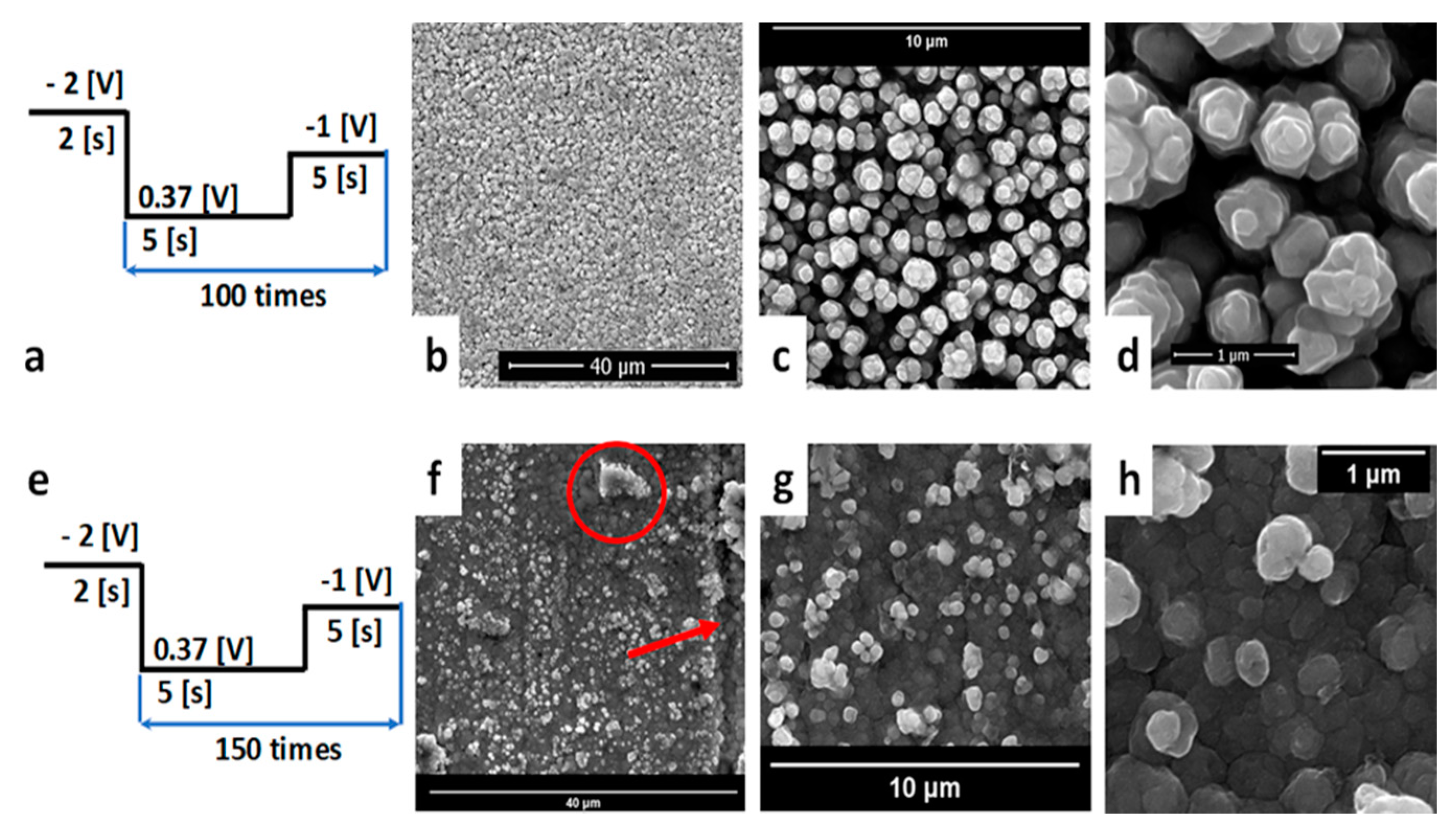
In Figure 5a,e, the schematic representation of the applied pulse scheme in each case is presented. It is visible that at 100 pulses, Figure 5b–d, the obtained grains are uniform, with a columnar appearance. They have columnar shape, with diameters about 500 nanometers. When the number of pulses was increased at 150, Figure 5f–h, some agglomerations are visible on top (marked with a red circle in Figure 5f, and some irregularities were also present, indicated with the red arrow in Figure 5f. The experiments were repeated at least three times and the results were consistent over at least three samples prepared in the same way.
For characterization experiments, the 100 pulses method was used, and the resulting sample was named OL/Cu pulsed. EDX spectra were recorded for this sample (image not shown), with the following results: CK 1.6 wt%, OK 1.5 wt%, NiL 5.36 wt% and CuL 91.54 wt%.

3.2.3. Copper Electrodeposition on OL/CNW

Copper deposition on OL/CNW was performed using the pulsed deposition. The same deposition parameters were used: alkaline electrolyte solution, temperature 50 °C, and number of pulses set to 100. This time E2 was 0.52 V, the open circuit potential being different in the presence of the nanowalls, as shown in Figure 6a. The SEM images corresponding to this sample are presented in Figure 6b–d. It is visible that grains are intercalated between carbon walls, as shown in Figure 6d. However, the obtained coating was not uniform and was very porous, having cracks (clearly visible in Figure 6b, indicated with a red arrow).
This behavior could be caused by the hydrophobic nature of the CNW surface. To test this hypothesis, the water contact angle was measured for this sample and the result was 132° ± 3°, confirming the hydrophobic surface. Studies on carbon nanostructured (CNT) surfaces showed that by the heat treatment, functional groups containing oxygen and defects were formed, leading to an improved surface hydrophilicity [47]. Thus, the OL/CNW surface was thermally treated to improve hydrophilicity at 100 degrees, for 2 h.
After the thermal treatment, this sample was electroplated with copper under the same conditions. In Figure 7a, the schematic representation of applied pulses is presented. This time, after thermal treatment, E2 is −0.03 V. SEM images are presented in Figure 7b–d, and the result was a uniform and homogeneous deposition with copper particles embedded and covering the CNW. This sample, named OL/CNW/Cu pulsed, was used for adherence, hardness, and electrochemical tests.

3.3. Copper Deposition by Magnetron Sputtering

3.3.1. Copper Deposition by Magnetron Sputtering on OL

Copper deposition was performed by magnetron sputtering using deposition parameters optimized in previous work [43], obtaining a uniformly distributed coating on the stainless-steel surface. This sample was named OL/Cu plasma. The Cu deposited by magnetron had a thickness of about 250 nm (SEM cross section image not shown). EDX spectra was recorded for this sample (image not shown), with the following results: C 3.07 wt%, O 2.04 wt%, Ni 5.04 wt% and Cu 89.86 wt%. The weight percentages are similar with the ones obtained for OL/Cu pulsed. J.R. Deepak and coworkers found a similar percentage of copper (96.01%) in the top layer electroplated on Corten A588 grade steel [23].

3.3.2. Copper Deposition by Magnetron Sputtering on OL/CNW

In Figure 8, it is visible that the coating is uniform, with reduced porosity, and uniform granular structures, CNW being beneficial for copper deposition. This sample was named OL/CNW/Cu plasma.

3.4. Mechanical Tests—Vickers, Adherence

3.4.1. Vickers Hardness Test

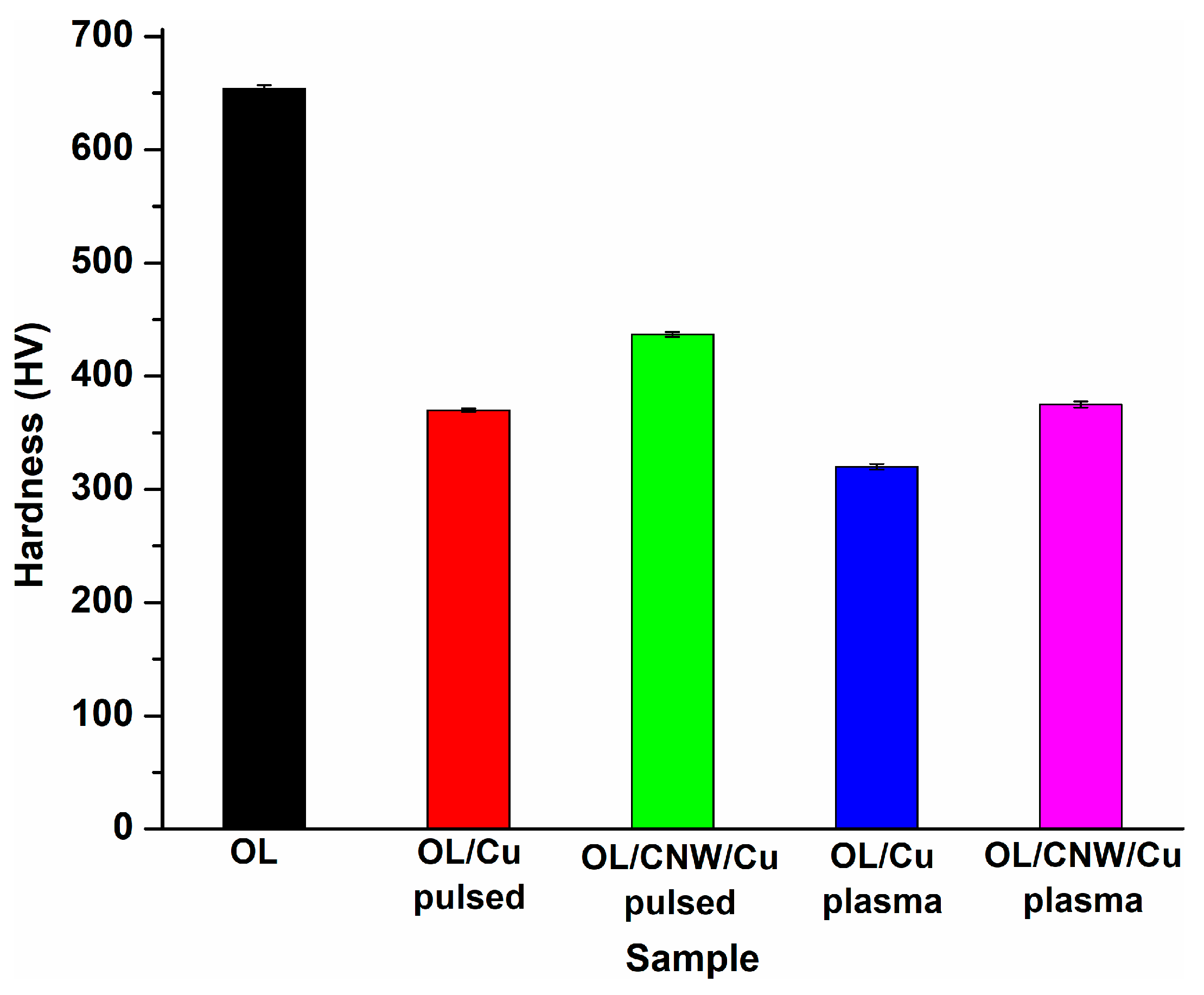
The hardness properties play an important role for coatings [48]. Thus, hardness was measured performing at least three different indentations, as shown in Figure 9.
The result for steel substrate was 654 ± 3 HV. The results obtained for the coatings are: OL/Cu pulsed 370 ± 1.5 HV, OL/Cu plasma 320 ± 2.5 HV, OL/CNW/Cu pulsed 437 ± 2 HV, and OL/CNW/Cu plasma 375 ± 2.7 HV.
The Vickers hardness depended on the processing conditions. The processing conditions can affect the grain size [49], and can lead to appearance of residual elements, voids, defects, or formation of compounds [50,51].
The hardness values obtained in this study must be regarded with precaution because the penetration depths are larger than the thickness of the deposited layer, so the contribution of the substrate to the measured hardness is important.
The observation that the harnesses of the films with the CNW interlayer are larger compared to those measured on OL/Cu is explainable by the fact that at the high plasma deposition temperature (700 °C) of CNW, the formation of a hard carbide compound at the interface with the steel is highly favored.
The hardness of copper-carbon nanowalls coatings is higher comparing with copper coatings. This is in good agreement with literature, wherein the hardness increased for other carbon-based coatings [29]. The obtained results are also higher than that reported by D Gupta and A K Sharma [10] regarding copper coated austenitic stainless steel; they measured values of 270 ± 30 HV, 256 ± 22 HV, and 267 ± 27 HV.

3.4.2. Adhesion Test

An adhesion test was performed on each coated sample and the obtained results are presented in Table 1.
The good results obtained for OL/Cu pulsed and OL/Cu plasma could be due to a very good substrate polishing by slide grinding before copper deposition, recent studies showing that more adherent coatings are obtained on ground substrates [52] and sandblasted samples [53].
A Cu coating of 150 microns using wire-arc spraying on 316 stainless steel was found to have an adhesion strength of 3.2 MPa during the pull-off adhesion test, the least adhesion strength compared to Cu 4%Sn, Cu 17%Al 1%Fe and Cu 17%Ni 9.6Zn coatings [21].
It was observed in the case of OL/CNW that the CNW coating was detached. The results are similar with observations reported in other works for CNTs [54]. However, all coated samples (OL/CNW/Cu pulsed and on OL/CNW/Cu plasma) had good adhesion (5B results). It was encouraging to see that after this adhesion test the examined area had no peeling of the coating. For OL/CNW/Cu, carbon nanostructures with their increased surface area, led to a good copper particles intercalation (seen in SEM images).

3.4.3. Electrical Resistivity Evaluation

The electrical resistivity of coated samples was evaluated, and the results are presented in Table 2. The values for the steel coated with copper using the pulsed or magnetron sputtering method have similar values of resistivity. It appears that the copper deposition method does not have an influence on conductivity. Copper/carbon nanowalls coatings have a slight increase of resistivity. These results are consistent with those obtained in other studies [55]. These CNW (multi-layer graphene oriented perpendicular to the substrate) showed the largest surface area compared to any other carbon materials. However, the presence of many porous-like air gaps and the buffer layer (an amorphous carbon layer) for nucleation decreased their electrical properties [56]. Fortunately, the resistivity increase was not a significant one; all the obtained values were below 2 Ω∙cm, lower than reported values of resistivity on pristine CNW deposited on Si wafers (close to 15 Ω∙cm) and CNW grown on the MWCNT-based buffer layer [56]. Resistivity was also lower compared to the one reported for CuNW-epoxy resin (EP) composite coating (3.44 × 10⁵ Ω·cm) and Cu@AgNW-EP composite (8.7 × 10³ Ω·cm). It satisfies the conductive requirement for electrostatic conductive materials, being below 104 Ω·cm [57].
200 μm copper coating deposited by low-pressure cold spraying on aluminum alloy showed lower electrical conductivity, which resulted from the high porosity of the coating and non-bonded particles [22]. WC−Cu composite coating prepared by electroplating was showing a high electrical conductivity [20].

3.5. Electrochemical Tests

3.5.1. Open Circuit Potential

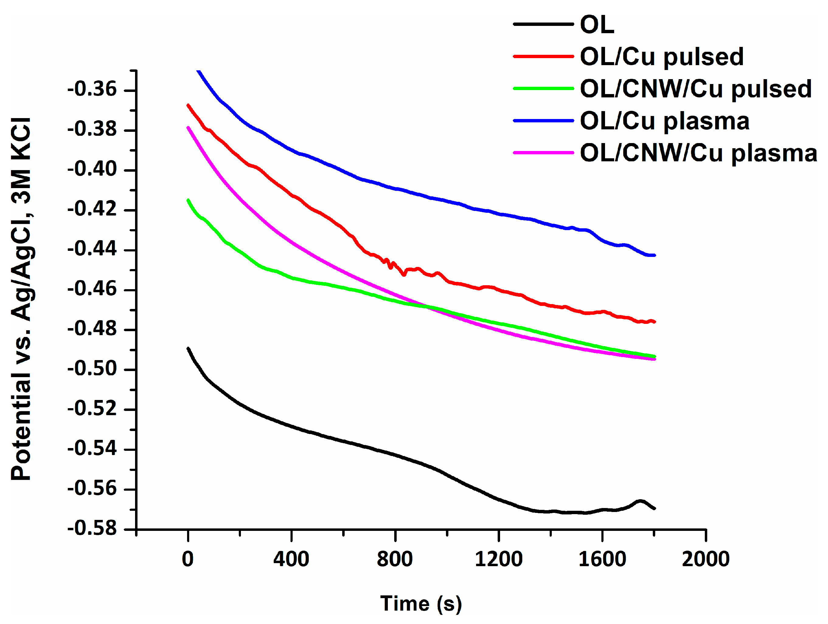
OCP determination in NaCl 0.9% for 1800 s revealed an electropositive potential shift of more than 100 mV for all coated samples comparing with uncoated OL, suggesting a corrosion surface stabilization after deposition (Figure 10). For all the investigated samples the potential showed a drop of approximately 50 mV followed by a slight stabilization tendency. Comparing OL/Cu pulsed with OL/CNW/Cu pulsed and OL/Cu plasma with OL/CNW/Cu plasma it can be seen that the presence of CNW brings a slight decrease in potential.

3.5.2. Tafel Analysis

Tafel analysis was performed in time, for 8 days, in aqueous NaCl 0.9% and the corrosion rate was estimated from Tafel slopes.
All coated samples have corrosion potentials more positive compared to OL substrate, as shown in Figure 11. The results are similar to those obtained in the literature. Copper coatings deposited by M. Winnicki and coworkers on aluminum alloy substrate material by low-pressure cold spraying showed a shift of corrosion potential towards more noble values as compared to the substrate material, during polarization measurements [22]. Cu coated on Corten A588 presented a higher corrosion potential (Ecorr) and lower corrosion current density (Icorr) compared to the substrate in 3.5% NaCl solution [23].
The corrosion rate of OL substrate (Figure 12) decreases after the first 24 h of immersion, then it has some small variations, and after 96 h of immersion, the corrosion rate shows an exponential growth.
For the sample OL/Cu pulsed (Figure 12), the corrosion rate is decreasing in time up to 0.01 mm/year after 192 h of immersion in NaCl 0.9%, a value lower compared to untreated OL. This is in good correlation with SEM images, in which a uniform copper layer without cracks is visible, in Figure 4b–d. For OL/CNW/Cu pulsed (Figure 12), the corrosion rate falls suddenly after the first 24 h and continues to remain lower than 0.14 mm/year for the next 192 h. Both pulsed samples present a decreasing tendency of the corrosion rate. However, CNW presence increases the corrosion rate in this case, probably due to the heat treatment performed before the Cu deposition. To test this hypothesis, an additional measurement of the Tafel plot was performed on an OL thermal treated in similar conditions (100 °C for 2 h). The results confirmed this hypothesis, the corrosion rate being higher after thermal treatment, 0.15 mm/year comparing with 0.088 mm/year and for OL.
For OL/Cu plasma (Figure 12), the initial corrosion rate is lower compared to OL and OL/Cu pulsed samples. This better behavior was also observed in OCP measurements in the first 30 min of immersion. The results are similar with those observed in the literature [58]. However, there is a tendency of the corrosion rate increasing in the last part of the tested interval, probably due to the breakdown of the passive layer formation during the corrosion process. OL/CNW/Cu plasma showed a stable tendency with low variations of the corrosion rate in time. The corrosion rate for OL/Cu plasma and OL/CNW/Cu plasma after 192 h had similar values.
Thus, Tafel analysis revealed a better corrosion behavior for pulsed electrochemically deposited samples. After 192 h, the OL/Cu pulsed sample showed the smallest value of corrosion rate, 0.01 mm/year. Samples with CNW (OL/CNW/Cu pulsed) presented values close to those of the substrate (OL).

4. Conclusions

Carbon nanowalls structures with high surface area were prepared on K455 steel as an interlayer to obtain CNW/copper coatings. The CNW led to a better distribution of copper on steel substrate, carbon nano-walls presence being beneficial for copper deposition.
Optimized pulse electrochemical deposition and magnetron sputtering deposition were applied to obtain uniform and adherent coatings. Adherence of the coating to the substrate was not influenced by CNW, since all coatings had good adherence (5B). CNW/copper coatings showed higher hardness values compared with copper coatings without CNW.
The electrical resistivity of the coating had a slow increase for samples with CNW (1.5 Ω·cm for OL/CNW/Cu pulsed compared to 0.91 Ω⋅cm for OL/Cu pulsed and 1.36 Ω·cm for OL/CNW/Cu plasma compared to 0.90 Ω⋅cm for OL/Cu plasma). Therefore, CNW’s presence did not have a strong influence on conductivity.
The presence of CNW brings a slight decrease in open circuit potential. Electrochemical analysis reveals a better corrosion behavior for pulsed electrochemically deposited samples. CNW presence does not have a significant influence on corrosion rate, as the corrosion rate after 192 h for OL/CNW/Cu pulsed is not very different from that of the steel substrate.
CNW-copper coated steel prepared in this study presented improved hardness and adhesion. Having lower surface electrical resistance, below 104 Ω·cm, it satisfies the conductive requirement for electrostatic conductive materials. CNW presence does not have a significant influence on the corrosion behavior of the substrate, for the Cu pulsed sample. Thus, these kinds of coatings could also be a promising material in aerospace, electronics, automotive, and power-generation applications.

Author Contributions

Conceptualization, C.P. and C.D.; methodology, C.-A.D., C.D., S.V. and C.P.; investigation, C.-A.D., C.D., B.B. and I.-M.N.; resources, C.P. and G.D.; writing—original draft preparation, C.-A.D., C.D., S.V. and I.-M.N.; writing—review and editing, C.P. and G.D.; supervision, C.P. All authors have read and agreed to the published version of the manuscript.

Funding

The work has been funded by the Operational Programme Human Capital of the Ministry of European Funds through the Financial Agreement 51668/09.07.2019, SMIS code 124705.

Institutional Review Board Statement

Not applicable.

Informed Consent Statement

Not applicable.

Acknowledgments

The authors want to acknowledge Catalin Constantin (INFLPR) for deposition of copper by magnetron sputtering. SEM analyses were possible due to the European Regional Development Fund through the Competitiveness Operational Program 2014–2020, Priority axis 1, Project No. P_36_611, MySMIS code 107066.

Conflicts of Interest

The authors declare no conflict of interest.

References

  1. Çakmakcı Ünver, İ.; Bereket, G.; Duran, B. Corrosion Protection of Stainless Steel by Poly(Carbazole-co-pyrrole) Films Deposited on TiO2 Sol–Gel Film. Polym.-Plast. Technol. Eng. 2018, 57, 242–250. [Google Scholar] [CrossRef]
  2. Isa, N.N.C.; Mohd, Y.; Mohamad, S.A.S.; Zaki, M.H.M. Antibacterial activity of copper coating electrodeposited on 304 stainless steel substrate. AIP Conf. Proc. 2017, 1901, 020009. [Google Scholar] [CrossRef]
  3. Yavuz, A.; Kaplan, K.; Bedir, M. Copper oxide coated stainless steel mesh for flexible electrodes. J. Phys. Chem. Solids 2021, 150, 109824. [Google Scholar] [CrossRef]
  4. Jaramillo-Gutiérrez, M.I.; Sierra-González, S.M.; Ramírez-González, C.A.; Pedraza-Rosas, J.E.; Pedraza-Avella, J.A. Effect of electrodeposition parameters and surface pretreatment on the electrochemical hydrogen production using nickel-plated stainless steel electrodes. Int. J. Hydrog. Energy 2021, 46, 7667–7675. [Google Scholar] [CrossRef]
  5. Attarzadeh, N.; Molaei, M.; Babaei, K.; Fattah-alhosseini, A. New Promising Ceramic Coatings for Corrosion and Wear Protection of Steels: A Review. Surf. Interfaces 2021, 23, 100997. [Google Scholar] [CrossRef]
  6. Soufeiani, L.; Foliente, G.; Nguyen, K.T.Q.; San Nicolas, R. Corrosion protection of steel elements in façade systems—A review. J. Build. Eng. 2020, 32, 101759. [Google Scholar] [CrossRef]
  7. Bekmurzayeva, A.; Duncanson, W.J.; Azevedo, H.S.; Kanayeva, D. Surface modification of stainless steel for biomedical applications: Revisiting a century-old material. Mater. Sci. Eng. C 2018, 93, 1073–1089. [Google Scholar] [CrossRef] [PubMed]
  8. Joy, N.; Sai Venkatesh, B.; Dilip Kumar, S. Microstructure and corrosion behavior of Cr-Cu and Cr-Ag composite coatings for industrial applications. Mater. Today Proc. 2021, 44, 3697–3700. [Google Scholar] [CrossRef]
  9. Asano, K.; Tsukamoto, M.; Sechi, Y.K.; Sato, Y.; Masuno, S.; Higashino, R.; Hara, T.; Sengoku, M.; Yoshida, M. Laser metal deposition of pure copper on stainless steel with blue and IR diode lasers. Opt. Laser Technol. 2018, 107, 291–296. [Google Scholar] [CrossRef]
  10. Gupta, D.; Sharma, A.K. Copper coating on austenitic stainless steel using microwave hybrid heating. Proc. Inst. Mech. Eng. Part E J. Process. Mech. Eng. 2011, 226, 132–141. [Google Scholar] [CrossRef]
  11. Flores, V.; Almanza, R. Behavior of the compound wall copper–steel receiver with stratified two-phase flow regimen in transient states when solar irradiance is arriving on one side of receiver. Sol. Energ. 2004, 76, 195–198. [Google Scholar] [CrossRef]
  12. Standish, T.; Chen, J.; Jacklin, R.; Jakupi, P.; Ramamurthy, S.; Zagidulin, D.; Keech, P.; Shoesmith, D. Corrosion of Copper-Coated Steel High Level Nuclear Waste Containers Under Permanent Disposal Conditions. Electrochim. Acta 2016, 211, 331–342. [Google Scholar] [CrossRef] [Green Version]
  13. Standish, T.E.; Zagidulin, D.; Ramamurthy, S.; Keech, P.G.; Noël, J.J.; Shoesmith, D.W. Galvanic corrosion of copper-coated carbon steel for used nuclear fuel containers. Corros. Eng. Sci. Technol. 2017, 52, 65–69. [Google Scholar] [CrossRef]
  14. Weinstein, M.; Falconer, C.; Doniger, W.; Bailly-Salins, L.; David, R.; Sridharan, K.; Couet, A. Environmental degradation of electroplated nickel and copper coated SS316H in molten FLiNaK salt. Corros. Sci. 2021, 191, 109735. [Google Scholar] [CrossRef]
  15. Molleda, F.; Mora, J.; Molleda, J.R.; Carrillo, E.; Mora, E.; Mellor, B.G. Copper coating of carbon steel by a furnace brazing process using brass as the braze. Mater. Charact. 2008, 59, 613–617. [Google Scholar] [CrossRef] [Green Version]
  16. Rivera, L.R.; Cochis, A.; Biser, S.; Canciani, E.; Ferraris, S.; Rimondini, L.; Boccaccini, A.R. Antibacterial, pro-angiogenic and pro-osteointegrative zein-bioactive glass/copper based coatings for implantable stainless steel aimed at bone healing. Bioact. Mater. 2021, 6, 1479–1490. [Google Scholar] [CrossRef]
  17. Aravindan, N.; Sangaranarayanan, M.V. Influence of solvent composition on the anti-corrosion performance of copper–polypyrrole (Cu–PPy) coated 304 stainless steel. Prog. Org. Coat. 2016, 95, 38–45. [Google Scholar] [CrossRef]
  18. Lü, X.; Lin, H. Facile fabrication of robust superhydrophobic/superoleophlic Cu coated stainless steel mesh for highly efficient oil/water separation. Sep. Purif. Technol. 2021, 256, 117512. [Google Scholar] [CrossRef]
  19. Rostami, R.; Moussavi, G.; Darbari, S.; Jafari, A.J. Non-thermal plasma by positive corona glow discharge using nano-structured Cu/CuO coated electrodes for benzene removal from air flow; removal enhancement and energy efficiency improvement. Sep. Purif. Technol. 2021, 275, 119156. [Google Scholar] [CrossRef]
  20. Zhao, Y.-C.; Tang, J.-C.; Ye, N.; Zhou, W.-W.; Wei, C.-L.; Liu, D.-J. Influence of additives and concentration of WC nanoparticles on properties of WC−Cu composite prepared by electroplating. Trans. Nonferrous Met. Soc. China 2020, 30, 1594–1604. [Google Scholar] [CrossRef]
  21. Ibrahim, M.; Al-Athel, K.; Arif, A.F.M. Strength and Hardness Assessment of Copper and Copper Alloy Coatings on Stainless Steel Substrates. In Proceedings of the ASME International Mechanical Engineering Congress and Exposition, Phoenix, AZ, USA, 11–17 November 2016; p. V014T011A019. [Google Scholar]
  22. Winnicki, M.; Małachowska, A.; Baszczuk, A.; Rutkowska-Gorczyca, M.; Kukla, D.; Lachowicz, M.; Ambroziak, A. Corrosion protection and electrical conductivity of copper coatings deposited by low-pressure cold spraying. Surf. Coat. Technol. 2017, 318, 90–98. [Google Scholar] [CrossRef]
  23. Deepak, J.R.; Bupesh Raja, V.K.; Kaliaraj, G.S. Mechanical and corrosion behavior of Cu, Cr, Ni and Zn electroplating on corten A588 steel for scope for betterment in ambient construction applications. Results Phys. 2019, 14, 102437. [Google Scholar] [CrossRef]
  24. Fihri, A.; Bovero, E.; Al-Shahrani, A.; Al-Ghamdi, A.; Alabedi, G. Recent progress in superhydrophobic coatings used for steel protection: A review. Colloids Surf. A Physicochem. Eng. Asp. 2017, 520, 378–390. [Google Scholar] [CrossRef]
  25. Ijaola, A.O.; Farayibi, P.K.; Asmatulu, E. Superhydrophobic coatings for steel pipeline protection in oil and gas industries: A comprehensive review. J. Nat. Gas Sci. Eng. 2020, 83, 103544. [Google Scholar] [CrossRef]
  26. Maizelis, A.A.; Bairachnyi, B.I.; Tul’skii, G.G. Contact Displacement of Copper at Copper Plating of Carbon Steel Parts. Surf. Eng. Appl. Electrochem. 2018, 54, 12–19. [Google Scholar] [CrossRef]
  27. Lin, C.; Hu, J.; Zhang, J.; Yang, P.; Kong, X.; Han, G.; Li, Q.; An, M. A comparative investigation of the effects of some alcohols on copper electrodeposition from pyrophosphate bath. Surf. Interfaces 2021, 22, 100804. [Google Scholar] [CrossRef]
  28. Wang, T.; Zhao, R.; Zhan, K.; Bao, L.; Zhang, Y.; Yang, Z.; Yan, Y.; Zhao, B.; Yang, J. Preparation of electro-reduced graphene oxide/copper composite foils with simultaneously enhanced thermal and mechanical properties by DC electro-deposition method. Mater. Sci. Eng. A 2021, 805, 140574. [Google Scholar] [CrossRef]
  29. Hannula, P.-M.; Peltonen, A.; Aromaa, J.; Janas, D.; Lundström, M.; Wilson, B.P.; Koziol, K.; Forsén, O. Carbon nanotube-copper composites by electrodeposition on carbon nanotube fibers. Carbon 2016, 107, 281–287. [Google Scholar] [CrossRef]
  30. Zhou, M.; Mai, Y.; Ling, H.; Chen, F.; Lian, W.; Jie, X. Electrodeposition of CNTs/copper composite coatings with enhanced tribological performance from a low concentration CNTs colloidal solution. Mater. Res. Bull. 2018, 97, 537–543. [Google Scholar] [CrossRef]
  31. Tamayo-Ariztondo, J.; Córdoba, J.M.; Odén, M.; Molina-Aldareguía, J.M.; Elizalde, M.R. Effect of heat treatment of carbon nanofibres on electroless copper deposition. Compos. Sci. Technol. 2010, 70, 2269–2275. [Google Scholar] [CrossRef] [Green Version]
  32. Barcena, J.; Maudes, J.; Coleto, J.; Baldonedo, J.L.; Gomez de Salazar, J.M. Microstructural study of vapour grown carbon nanofibre/copper composites. Compos. Sci. Technol. 2008, 68, 1384–1391. [Google Scholar] [CrossRef] [Green Version]
  33. Daoush, W.M.; Lim, B.K.; Mo, C.B.; Nam, D.H.; Hong, S.H. Electrical and mechanical properties of carbon nanotube reinforced copper nanocomposites fabricated by electroless deposition process. Mater. Sci. Eng. A 2009, 513–514, 247–253. [Google Scholar] [CrossRef]
  34. Hannula, P.-M.; Aromaa, J.; Wilson, B.P.; Janas, D.; Koziol, K.; Forsén, O.; Lundström, M. Observations of copper deposition on functionalized carbon nanotube films. Electrochim. Acta 2017, 232, 495–504. [Google Scholar] [CrossRef]
  35. Daoush, W.M.; Alkhuraiji, T.S.; Khamis, M.A.; Albogmy, T.S. Microstructure and electrical properties of carbon short fiber reinforced copper composites fabricated by electroless deposition followed by powder metallurgy process. Carbon Lett. 2020, 30, 247–258. [Google Scholar] [CrossRef]
  36. Bita, B.; Vizireanu, S.; Stoica, D.; Ion, V.; Yehia, S.; Radu, A.; Iftimie, S.; Dinescu, G. On the Structural, Morphological, and Electrical Properties of Carbon Nanowalls Obtained by Plasma-Enhanced Chemical Vapor Deposition. J. Nanomater. 2020, 2020, 8814459. [Google Scholar] [CrossRef]
  37. Stancu, E.C.; Stanciuc, A.-M.; Vizireanu, S.; Luculescu, C.; Moldovan, L.; Achour, A.; Dinescu, G. Plasma functionalization of carbon nanowalls and its effect on attachment of fibroblast-like cells. J. Phys. D Appl. Phys. 2014, 47, 265203. [Google Scholar] [CrossRef]
  38. Ion, R.; Vizireanu, S.; Stancu, C.E.; Luculescu, C.; Cimpean, A.; Dinescu, G. Surface plasma functionalization influences macrophage behavior on carbon nanowalls. Mater. Sci. Eng. C Mater. Biol. Appl. 2015, 48, 118–125. [Google Scholar] [CrossRef] [PubMed]
  39. MĂRĂSCU, V.; Vizireanu, S.; Stoica, S.; Barna, V.; Lazeastoyanova, A.; Dinescu, G. FTIR investigation of the ageing process of carbon nanowalls. Rom. Rep. Phys. 2016, 68, 1108–1114. [Google Scholar]
  40. Davami, K.; Jiang, Y.; Cortes, J.; Lin, C.; Shaygan, M.; Turner, K.T.; Bargatin, I. Tuning the mechanical properties of vertical graphene sheets through atomic layer deposition. Nanotechnology 2016, 27, 155701. [Google Scholar] [CrossRef]
  41. Cursaru, D.; Giagkas, N.; Vizireanu, S.; Mihai, S.; Matei, D.; BIŢĂ, B.; Stancu, C.; Manta, A.; Ramadan, I. Improvement of Antiwear Properties by Coating the Steel Surfaces and by Lubricant Additivation. Dig. J. Nanomater. Biostruct. 2019, 14, 907–915. [Google Scholar]
  42. Vizireanu, S.I.; Mitu, B.; Dinescu, G. Nanostructured carbon growth by expanding RF plasma assisted CVD on Ni-coated silicon substrate. Surf. Coat. Technol. 2005, 200, 1132–1136. [Google Scholar] [CrossRef]
  43. Surdu, L.; Visileanu, E.; Ardeleanu, A.; Mitran, C.; Rădulescu, I.R.; Stancu, C.; Sandulache, I.; Mitu, B. Research regarding the cover factor of magnetron sputtering plasma coated fabrics. Ind. Text. 2019, 70, 154–159. [Google Scholar]
  44. Imran, M.K.; Masood, S.H.; Brandt, M.; Bhattacharya, S.; Gulizia, S.; Jahedi, M.; Mazumder, J. Thermal fatigue behavior of direct metal deposited H13 tool steel coating on copper alloy substrate. Surf. Coat. Tech. 2012, 206, 2572–2580. [Google Scholar] [CrossRef]
  45. Krivchenko, V.A.; Itkis, D.M.; Evlashin, S.A.; Semenenko, D.A.; Goodilin, E.A.; Rakhimov, A.T.; Stepanov, A.S.; Suetin, N.V.; Pilevsky, A.A.; Voronin, P.V. Carbon nanowalls decorated with silicon for lithium-ion batteries. Carbon 2012, 50, 1438–1442. [Google Scholar] [CrossRef]
  46. Stoica, S.D.; Vizireanu, S.; Luculescu, C.R.; Mitu, B.; Dinescu, G. Metastable growth regime for carbon nanowalls and carbon nanofibers in an Ar/H2/C2H2 radiofrequency plasma jet. Plasma Sources Sci. Technol. 2020, 29, 105007. [Google Scholar] [CrossRef]
  47. Bao, S.; Wei, Q.; Cao, J.; Li, H.; Ma, L.; An, J.; Lin, C.-T.; Luo, J.; Zhou, K. Hydrophilic modification of carbon nanotube to prepare a novel porous copper network-carbon nanotube/erythritol composite phase change material. Compos. Interfaces 2021, 28, 175–189. [Google Scholar] [CrossRef]
  48. Anijdan, S.H.M.; Sabzi, M.; Zadeh, M.R.; Farzam, M. The effect of electroless bath parameters and heat treatment on the properties of Ni-P and Ni-P-Cu composite coatings. Mater. Res. (Sao Carlos Online) 2018, 21, 1–9. [Google Scholar] [CrossRef] [Green Version]
  49. Hakamada, M.; Nakamoto, Y.; Matsumoto, H.; Iwasaki, H.; Chen, Y.; Kusuda, H.; Mabuchi, M. Relationship between hardness and grain size in electrodeposited copper films. Mater. Sci. Eng. A 2007, 457, 120–126. [Google Scholar] [CrossRef]
  50. Bigl, S.; Schöberl, T.; Wurster, S.; Cordill, M.J.; Kiener, D. Correlative microstructure and topography informed nanoindentation of copper films. Surf. Coat. Technol. 2016, 308, 404–413. [Google Scholar] [CrossRef]
  51. Velicu, I.-L.; Ianoş, G.-T.; Porosnicu, C.; Mihăilă, I.; Burducea, I.; Velea, A.; Cristea, D.; Munteanu, D.; Tiron, V. Energy-enhanced deposition of copper thin films by bipolar high power impulse magnetron sputtering. Surf. Coat. Technol. 2019, 359, 97–107. [Google Scholar] [CrossRef]
  52. Boruah, D.; Robinson, B.; London, T.; Wu, H.; de Villiers-Lovelock, H.; McNutt, P.; Doré, M.; Zhang, X. Experimental evaluation of interfacial adhesion strength of cold sprayed Ti-6Al-4V thick coatings using an adhesive-free test method. Surf. Coat. Technol. 2020, 381, 125130. [Google Scholar] [CrossRef]
  53. Baiocco, G.; Rubino, G.; Ucciardello, N. Pretreatments effects on mechanical and morphological features of copper coatings. Surf. Interfaces 2020, 20, 100625. [Google Scholar] [CrossRef]
  54. Lee, S.W.; Kim, K.K.; Cui, Y.A.N.; Lim, S.C.; Cho, Y.W.; Kim, S.M.; Lee, Y.H. Adhesion Test of Carbon Nanotube Film Coated Onto Transparent Conducting Substrates. Nano 2010, 5, 133–138. [Google Scholar] [CrossRef]
  55. Nelyub, V. Methods for Developing Carbon Composites with Functional Properties. In Proceedings of the IOP Conference Series: Materials Science and Engineering Sevastopol, Sevastopol, Crimea, 7–11 September 2020; p. 022037. [Google Scholar]
  56. Kim, J.; Park, C.; Jung, H.; Kim, H.; Kwon, S.; Choi, H.; Kang, H. Study of a Carbon Nanowall Synthesized on an MWCNT-Based Buffer Layer for Improvement of Electrical Properties. Appl. Sci. 2020, 10, 192. [Google Scholar] [CrossRef] [Green Version]
  57. Zeng, N.; Ma, J.; Zhang, Y.; Yang, G.; Zhang, S.; Zhang, P. Silver nanosheet-coated copper nanowire/epoxy resin nanocomposites with enhanced electrical conductivity and wear resistance. J. Nanopart. Res. 2017, 19, 91. [Google Scholar] [CrossRef]
  58. Chakraborty, A.; Singh, J.K.; Sen, D.; Pityana, S.; Manna, I.; Krishna, S.; Dutta Majumdar, J. Microstructures, wear and corrosion resistance of laser composite surfaced austenitic stainless steel (AISI 304 SS) with tungsten carbide. Opt. Laser Technol. 2021, 134, 106585. [Google Scholar] [CrossRef]
Figure 1. Copper deposition on OL substrate and OL/CNW.
Coatings 11 01395 g001
Figure 2. Mounting of the four-point method.
Coatings 11 01395 g002
Figure 3. SEM images of carbon nano-walls deposition on K455 steel at different magnifications (ac), and FT-IR spectra for OL/CNW (d).
Coatings 11 01395 g003
Figure 4. SEM images of copper coatings at (a) 0.7, (b) 1, (c) 1.5 and (d) 2 V.
Coatings 11 01395 g004
Figure 5. Copper pulsed electrodeposition at 100 and 150 pulses. Schematic representation of applied pulses (a,e) and top view SEM images at different magnifications (bd,fh).
Coatings 11 01395 g005
Figure 6. Copper electrodeposition on CNW without thermal treatment: (a) schematic representation of applied pulses; (bd) corresponding SEM images.
Coatings 11 01395 g006
Figure 7. Copper electrodeposition on CNW heat treated: (a) schematic representation of applied pulses and (bd) top view SEM images at different magnifications.
Coatings 11 01395 g007
Figure 8. Corresponding SEM images of copper deposited by magnetron sputtering on CNW and steel substrate at different magnifications: (a) 10,000×, (b) 20,000×, (c) 40,000×.
Coatings 11 01395 g008
Figure 9. Vickers hardness for all coated samples.
Coatings 11 01395 g009
Figure 10. OCP determination in NaCl 0.9% vs. Ag/AgCl 3 M KCl for OL and all coated samples.
Coatings 11 01395 g010
Figure 11. Tafel slopes after 0 h of immersion (a), and 192 h of immersion (b).
Coatings 11 01395 g011
Figure 12. Corrosion rate in time for OL and all coated samples.
Coatings 11 01395 g012
Table 1. Adhesion test results.
SampleAdhesion Results
OL/CNW 3B
OL/Cu pulsed5B
OL/CNW/Cu pulsed5B
OL/Cu plasma5B
OL/CNW/Cu plasma5B
Table 2. Electrical resistivity ρ for copper coatings.
SampleResistivity (Ω⋅cm)
OL/Cu pulsed0.91
OL/CNW/Cu pulsed1.50
OL/Cu plasma0.90
OL/CNW/Cu plasma1.36
Publisher’s Note: MDPI stays neutral with regard to jurisdictional claims in published maps and institutional affiliations.