Article

An Atomization Model of Air Spraying Using the Volume-of-Fluid Method and Large Eddy Simulation

1
Department of Petroleum, Army Logistics University, Chongqing 401331, China
2
State Key Laboratory of NBC Protection for Civilian, Beijing 100097, China
*
Authors to whom correspondence should be addressed.
Coatings 2021, 11(11), 1400; https://doi.org/10.3390/coatings11111400
Submission received: 10 October 2021 / Revised: 31 October 2021 / Accepted: 9 November 2021 / Published: 18 November 2021

Abstract

:
When painting complex surfaces, such as large-curvature surfaces, poor coating quality is often obtained, which may be caused by lack of an appropriate atomization model, insufficient understanding of atomization mechanisms and laws, and improper painting parameters. This paper presents a numerical model of paint atomization of air spraying using the volume-of-fluid method and large eddy simulation. The interface capture and the turbulent flow were mainly considered in the model: the former was tracked by the volume-of-fluid method and the latter was predicted by the large eddy simulation. After the computational domain being meshed by the staggered-grid method, the governing equations were discretized by the finite volume method and were solved by the SIMPLE (Semi-Implicit Method for Pressure-Linked Equations) Consistent algorithm. The results of numerical simulations show that the characteristics of atomization flow field, such as velocity variation, pressure distribution, and paint volume fraction are in agreement with the regularities of atomization. Moreover, the primary and secondary atomization phenomena can be clearly observed: as soon as the paint issues from the nozzle, the paint flow begins to distort and the paint fragments continuously eject from the main paint flow and then these paint fragments distort and disintegrate into smaller elements. A comparison with the experimental data from the literature proves that the model of the whole atomization process of air spray is effective. The model is suitable for simulating the whole atomization process and easy to obtain initial conditions, which can be applied to set the appropriate painting parameters and study paint atomization mechanisms and laws in depth.

1. Introduction

Painting robots have been widely applied in the manufacture of airplanes [1], ships [2], automobiles [3] and other industrial products [4]. Complex surfaces are usually large curvature surfaces or narrow space surfaces, including spherical surface, V-shaped surface, intersecting surface, etc., which exist in many parts of these products, such as airplane noses and wings and car bumpers. When painting these surfaces, poor coating quality may be obtained, resulting in poor uniformity, bitty appearance, runs, cratering, orange peel, or film discoloration.
One of the main reasons causing the above problems is insufficient understanding of atomization mechanism and regularities, which may lead people to set inappropriate spray parameters (central atomizing air pressure, auxiliary atomizing air pressure, paint flow etc.) causing poor atomization. Modeling the paint atomization process to study the atomization mechanisms and regularities in depth is of great significance for solving the quality-control problem of painting complex surfaces.
Paint atomization in air spraying process is one of the complex issues about gas-liquid two-phase flows. There are some complex phenomena such as evaporation of organic solvent components in the paint and mass transfer through the vapour-liquid interface of mixtures during the atomization process [5]. Colbert et al. [6] found that the solvent evaporation from a droplet is negligible due to the short flight time by mass transfer calculations.
Experimental research involving an atomization process of air spray have been performed by Domnick et al. [7]. Due to the complexity and transiency of the spray flow field around the nozzle exit [8,9], it is hard to obtain the detailed and accurate data of the flow field close to the nozzle exit only by experiments and in depth research cannot be carried out.
With the development of simulation technology, the computational fluid dynamics (CFD) method has become a powerful tool to model the two-phase flow field. Many researchers [10,11,12,13] have studied the coating-forming process of air spraying by CFD modeling. However, less research on modeling air spraying atomization can be found in the literature and the lack of a suitable CFD model has become the main constraint.
Only the TAB (Taylor analogy breakup) model is reported to model paint atomization. The TAB model was first used to predict fuel atomization [14,15], and recently, Li et al. [16] and Wang et al. [17] have applied it to paint an atomization simulation of air sprays. However, the TAB model only considers the secondary atomization and requires empirical initial conditions to solve the model. In comparison, the interface-tracking approach, VOF (volume of fluid), is more competent for paint atomization modeling. The VOF method computes the volume fraction of a particular phase and is naturally volume-conserved, it can track interface location and topology as accurately as possible, and has been widely used in fuel injection modeling [18,19,20].
Turbulence modeling is another problem in modeling paint atomization of air spray, which can be solved by three methods: Reynolds averaged Navier–Stokes (RANS), direct numerical simulation (DNS) and large eddy simulation (LES). The RANS method adopts the time-averaged theory to solve the governing equations. It has the advantages of low requirements for spatial resolution and small calculation workload. Payri et al. [21] and Jacobsohn et al. [22] applied RANS to tackle the turbulence effect and observe the cavitation phenomenon in fuel injection. However, that method is not adequate in some situations and only provides averaged turbulence information, which makes it incompetent for profound research on atomization mechanisms and regularities. DNS is the most accurate approach to turbulence simulation, and it solves the Navier–Stokes equations without averaging or approximation. However, the results of a DNS contain far more information than any atomization researcher demands and DNS is too expensive to be employed very often. Therefore, it currently cannot be applied to atomization simulation.
LES is a technique that is a good compromise between the less accurate RANS and expensive DNS. It divides the turbulence into large- and small-scales eddies by a spatially filtering function and treats the large eddies more exactly than the small ones. Many scholars, such as Dianat et al. [23] have applied LES to research fuel injection atomization and combustion. LES is the preferred method for paint atomization of gas-liquid two-phase flow in which the Reynolds number is too high or the geometry is too complex to allow the application of DNS.
This paper provides a numerical model using the volume-of-fluid method and large eddy simulation for simulating the paint atomization of an air spray. In Section 2, the CFD-based paint atomization model is established. Then the numerical method for solving this model is described in Section 3. In Section 4, validation of the model proposed in this paper is verified. Finally, conclusions are drawn, and future works are suggested. In actual applications the present contribution can be used to set the appropriate painting parameters, and study paint atomization mechanisms and laws in depth.

2. Paint Atomization Model of Air Spray

2.1. Basic Governing Equations

In order to simplify and solve the atomization model, two assumptions that retain the essential mechanisms and neglect less influential ones were needed. Firstly, the paint studied is assumed to be a Newtonian fluid, although paint is a non-Newtonian fluid. In addition, it is assumed that there is no mass transfer from the paint to the air and no temperature change of the paint and air during the atomization process. Since the atomization process only lasts a few milliseconds, the evaporation of the solvent and the temperature change of the paint are negligible. Therefore, when establishing the atomization model, it is considered that there is no energy exchange between the spray flow field and the surrounding air, and the energy equation may not be established.
Mass conservation equation and momentum conservation equation [24] are:
u = 0
u t + ( u u ) = 1 ρ p + 1 ρ ( 2 μ S ) + f + 1 ρ F s
where u is the velocity of flow; t is time; ρ is the flow density; p is the space pressure; μ is the dynamic viscosity of flow; S is the viscous stress tensor; f is the force per unit mass; Fs is surface tension of flow.

2.2. Interface Capture Model

The VOF method performs air–paint interface tracking by solving the continuity equations of two-phase volume fractions. The volume fraction of each phase in each control volume is defined as:
α q = { 1 only   phase   q   exists   in   the   control   volume     0 < α q < 1 both   two   phases   exist   in   the   control   volume   0 no   phase   q   exists   in   the   control   volume  
where q stands for gas phase or paint phase.
For arbitrary control volume in the atomization flow field, both the volume fraction of gas phase αg and the volume fraction of paint phase αp obey the following constraints:
α g + α p = 1
Thus, the continuity equation can be written as:
α q t + ( α q u ) = 0
where u represents the velocity of phase q.
In the whole flow field, the velocity field is shared by all phases, the momentum equation has the following form:
( ρ u ) t + ( ρ u u ) = p + [ μ ( u + u T ) ] + ρ g + F σ
where ρ and μ represent the averaged density and averaged dynamic viscosity:
ρ = α ρ l + ( 1 α ) ρ g
μ = α μ l + ( 1 α ) μ g
Fσ represent the pressure increase caused by interfacial tension, which is defined as:
F σ = σ κ n
where σ is the surface tension coefficient. κ is the two-phase interface curvature, κ = n ; n is unit vector normal to the interface.

2.3. Turbulence Model

The atomization turbulence is modeled by LES method, which separates large- and small-scale eddies from the turbulence components by averaging the turbulence variables referred to in the atomization process.
For an arbitrary turbulence variable, its large-scale component is defined as:
F ¯ ( x , t ) = Ω H ( x x , Δ ) F ( x , t ) d x
where H ( x x , Δ ) is the spatial filtering function, + H ( x x , Δ ) d x = 1 ; Ω is the computational domain; Δ is the filter width, which can be estimated as:
Δ = V 1 / 3 = ( Δ x Δ y Δ z ) 1 / 3
Thereby the filtered conservation equations can be expressed as:
u ¯ = 0
u ¯ t + ( u ¯ u ¯ ) = 1 ρ p ¯ + [ μ ρ u ¯ + μ ρ ( u ¯ ) T ] F σ ρ + g + F S G S
where FSGS represents the sublattice-scale turbulent pulsation strength, which is defined as:
F S G S = τ i j x j
where τij is the subgrid-scale turbulence stress generated during filter:
τ i j =   ρ ( u u ¯ u ¯ u ¯ )

3. Numerical Simulation

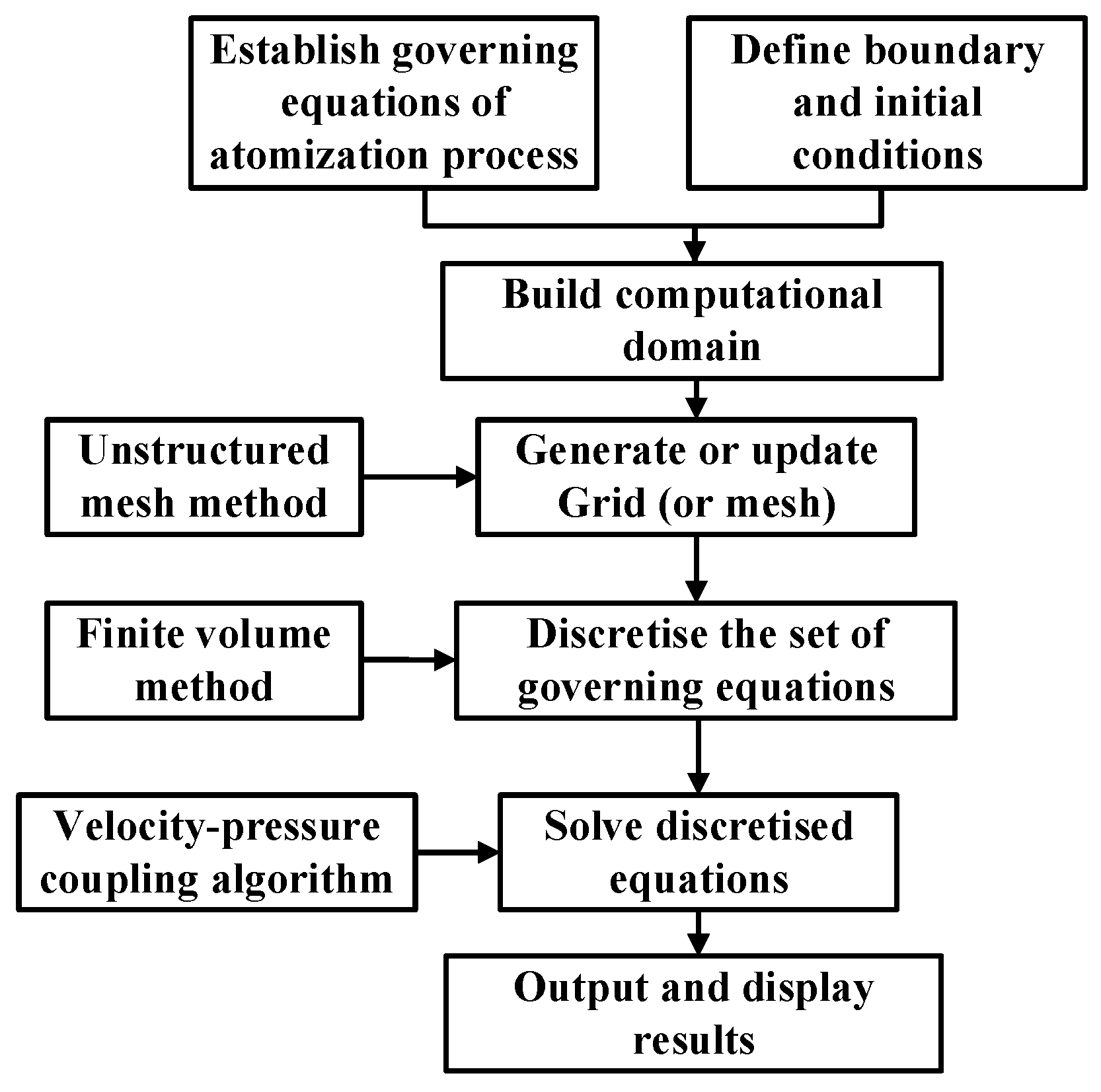
3.1. Simulation Process

The numerical simulation process of air spray atomization based on CFD is shown in Figure 1. Firstly, the atomization governing equations are established according to the physical process of paint atomization, and 2D computational domain for spray flow field is constructed with initial conditions and boundary conditions defined, such as physical parameters of phases and boundary types. Then unstructured mesh method is adopted to mesh the computational domain and refine the local areas with intense velocity gradients. Finally, the related information of the atomization flow field of air spray is obtained by solving the atomization model established using the velocity-pressure coupling algorithm.

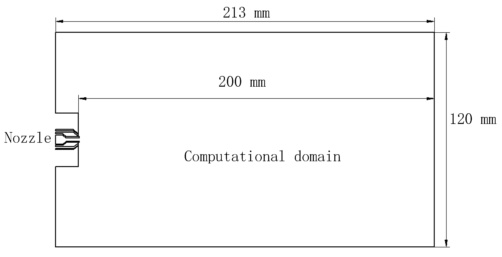
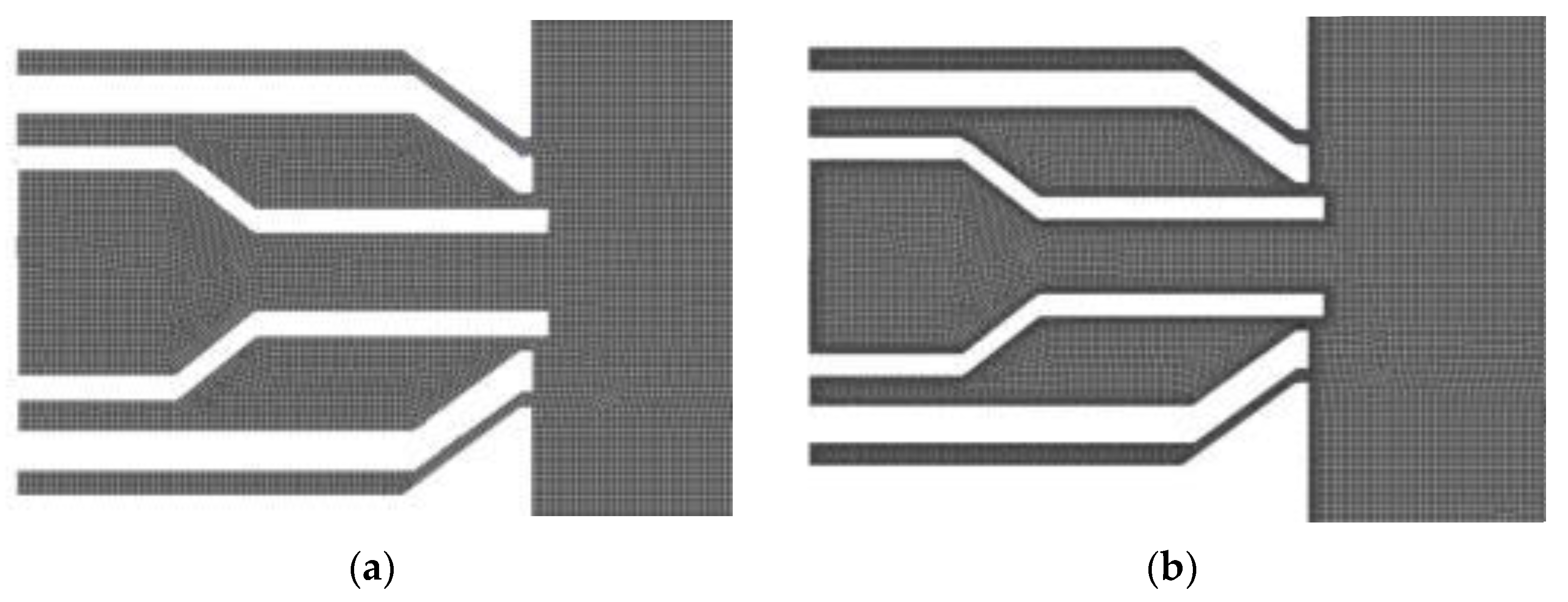
3.2. Computational Domain and Initial Mesh

The computational domain of the two-dimensional atomization flow field is a rectangular region (213 mm × 120 mm) where the spray nozzle is located at the midpoint of the left edge (Figure 2). The central channel is the paint ejection channel, and the central atomizing air ejection channel and the auxiliary atomizing air ejection channel are on both sides (Figure 3). The data in Table 1 are the geometric parameters of the nozzle.
In order to obtain high-quality mesh, the mesh of the boundary of two-phase ejection channels was refined (Figure 4). The whole computational domain was meshed with 950,000 grids, where the grid quality mean and averaged skewness is 0.995 and 4.96 × 10⁻³ respectively.

3.3. Parameter Settings of Atomization Simulation

The atomization process of spraying paint involves two phases (liquid paint and air) among which the air was defined as the first phase and the liquid phase as the second phase. Properties of the relevant substances in this paper are shown in Table 2.
Air sources of atomization mainly include central atomizing air and auxiliary atomizing air. The corresponding air ejection channels were set as pressure inlets, with air pressure 121 and 81 kPa, the turbulence intensity 5% and 5%, and the hydraulic diameters 0.4 and 0.8 mm. The liquid ejection channel was set as velocity inlet, with paint velocity 1.42 m/s, turbulence intensity 10%, hydraulic diameter 2 mm, and working pressure 1 atm.
Numerical simulations of atomization process were carried out using ANSYS Fluent (version 16.0) as the following steps:
Firstly, import the geometry model of the nozzle into Fluent and perform meshing.
Then, select the VOF in the multiphase flow model and LES in the viscous flow model, and define the materials and boundary conditions as shown in Section 3.2 and Section 3.3. In the solution module, select the SIMPLEC (SIMPLE (Semi-Implicit Method for Pressure-Linked Equations) Consistent) algorithm for the pressure-velocity coupling solution, and select “Least Squares Cell Based”, “PRESTO!”, “Bounded Central Difference” and “Geo-Reconstruct” for the gradient term, pressure term, momentum term and volume fraction term in the spatial discrete equation, respectively.
Finally, check the case and run the calculation with a fixed time step of 1 × 10⁻⁷ s.

4. Model Verification

In order to verify this proposed model, the velocity, pressure and liquid-phase volume fraction distributions of the spray flow field were analyzed and compared with the atomization experimental data by Fogliati et al. [7].

4.1. Numerical Simulation Results

At 9.0–9.2 ms the paint jetted out and the atomization flow field was in a steady state at about 15 ms. Therefore, the atomization flow field data at 9.0, 9.2, 9.5, 12 and 15.0 ms were taken for analysis.
The states of paint atomization at the different times is visualized in Figure 5. Figure 5a shows the paint flow that arrived at the exit at about 9.2 ms. The head of the paint flow presents a long slope along the direction of movement with several paint fragments scattered.
In Figure 5, as soon as the paint issues from the nozzle, deformations appear on the two-phase interface. These deformations grow in space and time and eventually result in the ejection of paint fragments from the main paint flow. The paint fragments diffuse with the air flow in the space and the distribution of flow field expands. The variation of the atomization flow pattern simulated accords with the basic regularity of paint atomizing. The radial distributions paint volume fraction at different time points at different distances from the nozzle tip is demonstrated in Figure 6, which is consistent with the information reflected by Figure 5. From Figure 6, the time of the spraying flow field becoming stable is at approximately 12 ms.
The maximum velocity of paint in the spray flow field varies as shown in Figure 7. During 0–9.0 ms, there is only air in the flow field. The maximum velocity boosts rapidly, then tends to be stable; during 9.0–9.5 ms, the paint arrives to the flow field and the paint velocity reaches a peak; in the remaining time the maximum fluctuated at a certain value. The whole variation of the maximum velocity can be reasonably explained by visualization data of paint atomizing.
Figure 8 represents the pressure distribution of the spray flow field with the maximum pressure area shown in red and the minimum pressure area shown in blue. The whole pressure distribution of the flow field is relatively symmetrical with the central axis as the symmetry axis, especially that near the nozzle exit. Some areas are under subatmospheric pressure, resulting from a large amount of air vortices in the spray flow field.
In Figure 9, paint flow is displayed by its volume fraction, and air flow is displayed by the velocity vectors. As shown in Figure 9, after flowing out from the nozzle, the continuous paint flow begins to break up under the impact of high-velocity airflow nearby. During 10.33–10.34 ms, influenced by the high-velocity gas stream from a ring gas nozzle, the paint flow gradually deforms. Then the tail falls off from the main liquid column to form independent paint liquid masses, and the formation of paint liquid masses is consistent with the primary atomization theory [12]. During 10.35–10.40 ms, the paint liquid masses distort and disintegrate into new smaller paint droplets with the continued impact of a high-velocity airflow and air vortex, which is in accordance with the secondary atomization theory. This process is repeated until these elements are spraying in a stable way.

4.2. Result Comparison

To further verify the proposed atomization model, the numerical simulation results were compared with Fogliati’s experimental results. Fogliati et al. set water as liquid phase to conduct an atomization experiment. They measured the axial and radial spray velocities of the atomization flow field at 40 and 100 mm away from the nozzle, and studied the expansion degree of the atomization flow field by analyzing the relationship between dimensionless liquid velocities ( U / U max , V / V max ) and dimensionless coordinate Y / Y ( U 50 % ) . The initial related parameters of numerical simulation and experiment are shown in Table 3.
At the time 18.0 ms, the spray atomization state are shown as Figure 10 and Figure 11. Figure 10 presents the distribution of water atomized in the two-dimensional plane, the maximum of water volume fraction is set to 1%; Figure 11 presents the distribution of water velocity in the two-dimensional plane, the maximum of spray velocity is set to 517 m/s.
The comparison between simulation results and experimental results is shown in Figure 12 and Figure 13. In Figure 12, the ordinate U / U max represents the dimensionless spray velocity in the axial direction, where U max is the maximum at the coordinate X. In Figure 13, the ordinate V / V max represents the dimensionless spray velocity in the radial direction, where V max is the maximum. The abscissas Y / Y ( U 50 % ) of the two figures represent the dimensionless radial distance, where Y ( U 50 % ) is the abscissa value corresponding to half of the maximum axial spray velocity.
Whether at the distance of 40 or 100 mm away from the nozzle exit, the simulation results for water seem to be in good agreement with Fogliati’s experimental results; nevertheless, a difference can also be observed between simulation and experiment due to the following reasons: firstly, the 2D geometric model used in this study can yield different results; secondly, the material properties of the paint are different from those of the water.
In conclusion, the simulation results conform to the regularity of the atomization process and are in good agreement with the experimental data, which proves that the air spray atomization model proposed in this paper is reasonable.

5. Conclusions

In this study, a numerical model using the volume-of-fluid method and large eddy simulation was proposed for simulating the paint atomization process in an air spray. This model includes an interface capture model and a turbulence model. A high-precision method for solving the model was constructed by coupling the finite volume method, the staggered grid method and the SIMPLEC algorithm. Compared with the TAB atomization model, the established model can describe the whole process of paint atomization, and its initial conditions are easy to obtain, but cannot predict the droplet sizes.
The numerical simulation results clearly demonstrate the accordance with the regularity of the atomization process. The primary and secondary atomization phenomena can be clearly observed: as soon as the paint issues from the nozzle, the paint flow begins to distort and the paint fragments continuously eject from the main paint flow, and then these paint fragments distort and disintegrate into smaller elements. Additionally, good agreement can be found between the simulation results with experimental data from literature, which proves that the proposed model is reasonable.
Based on the present numerical results, the following studies will be conducted in the future. A 3D simulation with more details will be carried out for deeper analysis of atomization mechanism and laws. Moreover, the simulation accuracy could be greatly heightened by improving the model with the multi-scale method.

Author Contributions

Formal analysis: S.C.; methodology: S.C.; project administration: Y.C.; software: S.C.; supervision: Y.C. and J.J.; validation: J.H.; writing—original draft: S.C.; writing—review and editing: Y.C. and W.C. All authors have read and agreed to the published version of the manuscript.

Funding

This project is supported by the National Natural Science Foundation of China (Grant No. 51475469), the State Key Laboratory of NBC Protection for Civilian (Grant No. SKLNBC2020-09), and the Science and Technology Research Program of Chongqing Municipal Education Commission (Grant Nos. KJZD-M201912901 and KJZD-K202012903).

Institutional Review Board Statement

Not applicable.

Informed Consent Statement

Not applicable.

Data Availability Statement

Data sharing is not applicable to this article.

Conflicts of Interest

The authors declare no conflict of interest.

References

  1. Neal, A.S.; Jonathan, A.B.; Ron, K.F. Precision robotic coating application and thickness control optimization for f-35 final finishes. SAE Int. J. Aerosp. 2009, 2, 284–290. [Google Scholar]
  2. Chen, H.P.; Xi, N. Automated tool trajectory planning of industrial robots for painting composite surfaces. Int. J. Adv. Manuf. Technol. 2008, 35, 680–696. [Google Scholar] [CrossRef]
  3. Chen, W.; Chen, Y.; Li, B.; Zhang, W.; Chen, K. Design of redundant robot painting system for long non-regular duct. Ind. Robot Int. J. 2016, 43, 58–64. [Google Scholar] [CrossRef]
  4. Xie, F.G.; Liu, X.J.; Wu, C.; Zhang, P. A novel spray painting robotic device for the coating process in automotive industry. Proc. Inst. Mech. Eng. Part C J. Mech. Eng. Sci. 2015, 229, 2081–2093. [Google Scholar] [CrossRef]
  5. Stephan, S.; Hasse, H. Enrichment at vapour–liquid interfaces of mixtures: Establishing a link between nanoscopic and macroscopic properties. Int. Rev. Phys. Chem. 2020, 39, 319–349. [Google Scholar] [CrossRef]
  6. Colbert, S.A.; Cairncross, R.A. A discrete droplet transport model for predicting spray coating patterns of an electrostatic rotary atomizer. J Electrost. 2006, 64, 234–246. [Google Scholar] [CrossRef]
  7. Domnick, J.; Lindenthal, A.; Tropea, C.; Xu, T.H. Application of phase doppler anemometry in paint sprays. At. Sprays. 1994, 4, 437–450. [Google Scholar]
  8. Luo, H.; Nishida, K.; Uchitomi, S.; Ogata, Y.; Zhang, W.; Fujikawa, T. Microscopic behavior of spray droplets under flat-wall impinging condition. Fuel 2018, 219, 467–476. [Google Scholar] [CrossRef]
  9. Kim, H.; Kim, J.; Park, S. Atomization characteristics of aerosol spray from hair spray vessel with various design parameters. J. Aerosol Sci. 2019, 133, 24–36. [Google Scholar] [CrossRef]
  10. Chen, W.Z.; Chen, Y.; Zhang, W.M.; He, S.W.; Li, B.; Jiang, J.Z. Paint thickness simulation for robotic painting of curved surfaces based on Euler–Euler approach. J. Braz. Soc. Mech. Sci. Eng. 2019, 41, 199. [Google Scholar] [CrossRef]
  11. Chen, Y.; Chen, W.Z.; Li, B.; Zhang, G.; Zhang, W.M. Paint thickness simulation for painting robot trajectory planning: A review. Ind. Robot. Int. J. 2017, 44, 629–638. [Google Scholar] [CrossRef]
  12. Fogliati, M.; Fontana, D.; Garbero, M.; Vanni, M.; Baldi, G.; Donde, R. CFD simulation of paint deposition in an air spray process. JCT Res. 2006, 3, 117–125. [Google Scholar] [CrossRef]
  13. Ye, Q.; Pulli, K. Numerical and experimental investigation on the spray coating process using a pneumatic atomizer: Influences of operating conditions and target geometries. Coatings. 2017, 7, 13. [Google Scholar] [CrossRef] [Green Version]
  14. Shin, J.; Kim, D.; Seo, J.; Park, S. Effects of the physical properties of fuel on spray characteristics from a gas turbine nozzle. Energy. 2020, 205, 118090. [Google Scholar] [CrossRef]
  15. AlZahrani, A.A.; Dincer, I. Modeling of n-Hexane and n-Octane liquid fuel jets in gaseous crossflow for evaporation, combustion and breakup evaluation. Int. Commun. Heat Mass Transf. 2017, 88, 203–210. [Google Scholar] [CrossRef]
  16. Li, W.; Qian, L.; Song, S.; Zhong, X. Numerical study on the influence of shaping air holes on atomization performance in pneumatic atomizers. Coatings. 2019, 9, 410. [Google Scholar] [CrossRef] [Green Version]
  17. Wang, Y.A.; Xie, X.P.; Lu, X.H. Design of a double-nozzle air spray gun and numerical research in the interference spray flow field. Coatings. 2020, 10, 475. [Google Scholar] [CrossRef]
  18. Ghate, K.; Muthuselvan, G.; Sundararajan, T. Modeling of primary and secondary atomization with simplex atomizers. Multiph. Sci. Technol. 2020, 32, 237–258. [Google Scholar] [CrossRef]
  19. Giussani, F.; Piscaglia, F.; Saez-Mischlich, G.; Hèlie, J. A three-phase VOF solver for the simulation of in-nozzle cavitation effects on liquid atomization. J. Comput. Phys. 2020, 406, 109068. [Google Scholar] [CrossRef]
  20. Gurakov, N.I.; Zubrilin, I.A.; Abrashkin, V.Y.; Morales, M.H.; Yakushkin, D.V.; Yastrebov, V.V.; Kolomzarov, O.V.; Idrisov, D.V. Validation of the VOF method for liquid spray process simulation from a pressure-swirl atomizer. AIP Conf. Proc. 2020, 2304, 020031. [Google Scholar]
  21. Payri, R.; Giraldo, J.S.; Ayyapureddi, S.; Versey, Z. Experimental and analytical study on vapor phase and liquid penetration for a high pressure diesel injector. Appl. Therm. Eng. 2018, 137, 721–728. [Google Scholar] [CrossRef]
  22. Jacobsohn, G.L.; Mohapatra, C.K.; Grover, R.O.; Duke, D.J.; Schmidt, D.P. Comparison of turbulence modeling methods for evaluating GDI sprays with transient needle motion. Presented at the SAE World Congress Exper (WCX2019), Detroit, MI, USA, 9–11 April 2019. [Google Scholar]
  23. Xiao, F.; Dianat, M.; McGuirk, J.J. LES of turbulent liquid jet primary breakup in turbulent coaxial air flow. Int. J. Multiph. Flow. 2013, 60, 103–118. [Google Scholar] [CrossRef] [Green Version]
  24. Zou, W.; He, Z.; Gu, X. Viscous Fluid Dynamics, 1st ed.; National Defense Industry Press: Beijing, China, 2013; pp. 128–133. [Google Scholar]
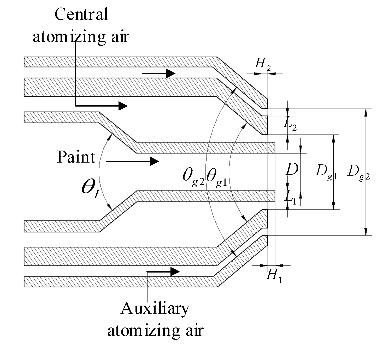
Figure 1. Numerical simulation process of air spray atomization.
Coatings 11 01400 g001
Figure 2. Computational domain of two-dimensional model.
Coatings 11 01400 g002
Figure 3. Nozzle geometry.
Coatings 11 01400 g003
Figure 4. Mesh generation of nozzle. (a) Before refinement. (b) After refinement.
Coatings 11 01400 g004
Figure 5. Visualization of paint atomization at different time. (a) 9.2 ms. (b) 9.5 ms. (c) 12 ms. (d) 15 ms.
Coatings 11 01400 g005
Figure 6. Volume fraction distribution of radial paint at different time at different distance along the central axis. (a) 9.2 ms. (b) 9.5 ms. (c) 12 ms. (d) 15 ms.
Coatings 11 01400 g006
Figure 7. Variation of the maximum velocity in the spray flow field.
Coatings 11 01400 g007
Figure 8. Pressure distribution in the spray flow field at time 15 ms.
Coatings 11 01400 g008
Figure 9. Screenshots of the transient animation of paint droplet formation.
Coatings 11 01400 g009
Figure 10. Volume fraction distribution of water.
Coatings 11 01400 g010
Figure 11. Velocity distribution of water.
Coatings 11 01400 g011
Figure 12. Relationship between dimensionless axial velocity and radial distance. (a) X = 40 mm. (b) X = 100 mm.
Coatings 11 01400 g012
Figure 13. Relationship between dimensionless radial velocity and radial distance. (a) X = 40 mm. (b) X = 100 mm.
Coatings 11 01400 g013
Table 1. Geometrical parameters of nozzle.
Parameter SymbolDDg1Dg2L1L2H1H2θ1θg1θg2
Size2.0 mm4.0 mm7.6 mm0.6 mm1.0 mm0.4 mm0.3 mm78°80°80°
Table 2. Substance properties in simulations.
SubstanceDensityViscositySurface TensionReference
Temperature
Paint1200 kg/m30.097 kg/(m·s)0.0287194 N/m298.15 K
Air1.225 kg/m30.000017894 kg/(m·s)298.15 K
Water998.2 kg/m30.001003 kg/(m·s)0.0719404 N/m298.15 K
Table 3. Comparison of atomization parameters (MI: medium inlet, TI: turbulence intensity, HD: hydraulic diameter, PI: pressure inlet).
TypeEjection Conditions of Liquid PhaseEjection Conditions of Central Atomizing AirEjection Conditions of Auxiliary Atomizing Air
Medium TypeMITIHDPITIHDPITIHD
Simulation 1Paint1.42 m/s5%1 mm121 kPa5%0.5 mm81 kPa5%0.4 mm
Simulation 2Water3 cm3/s10%1 mm152 kPa10%0.5 mm121 kPa10%0.4 mm
FogliatiWater3 cm3/s10%2 mm150 kPa10%0.5 mm120 kPa10%0.5 mm
Publisher’s Note: MDPI stays neutral with regard to jurisdictional claims in published maps and institutional affiliations.

