
Creation of Bioceramic Coatings on the Surface of Ti–6Al–4V Alloy by Plasma Electrolytic Oxidation Followed by Gas Detonation Spraying


Abstract
:1. Introduction
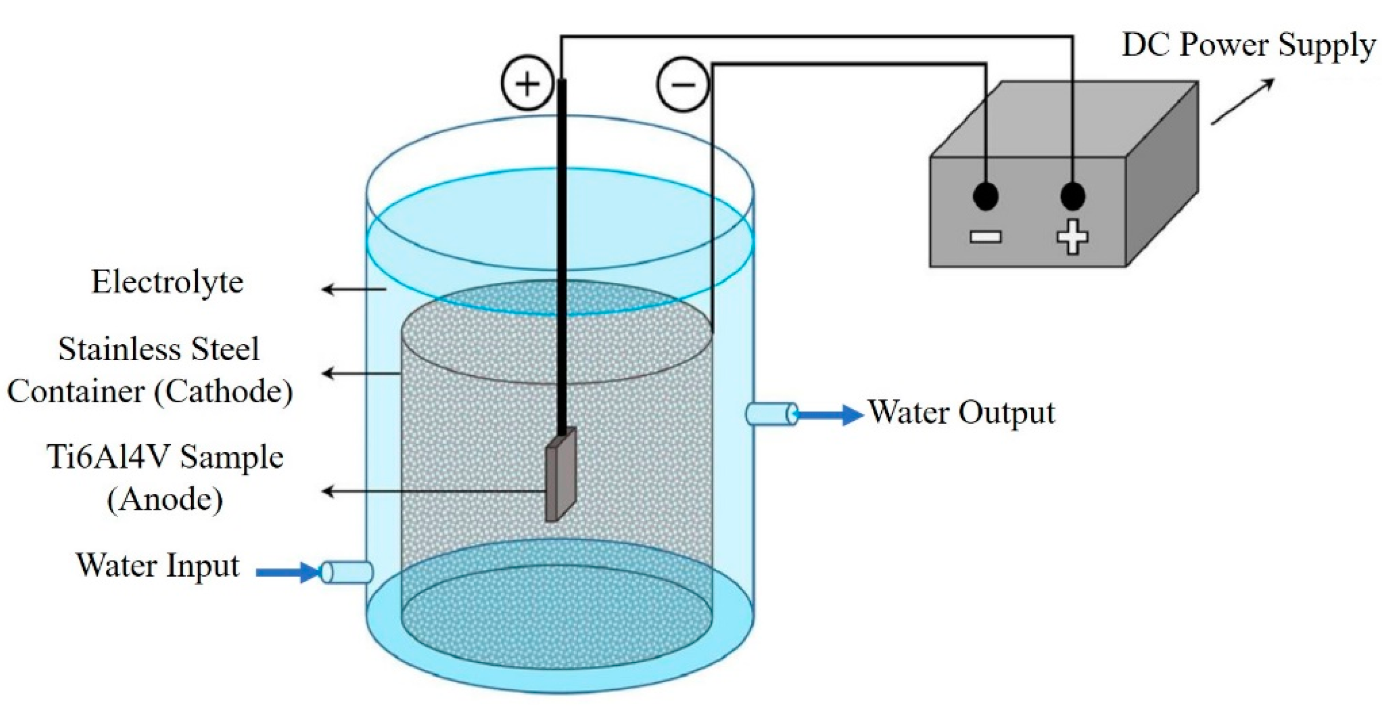
2. Materials and Methods
3. Results and Discussion
4. Conclusions
Author Contributions
Funding
Institutional Review Board Statement
Informed Consent Statement
Data Availability Statement
Conflicts of Interest
References
- Duan, Y.; Ma, W.; Baolin, L.; Wang, T.; Liu, B. Enhanced osseointegration of titanium implants in a rat model of osteoporosis using multilayer bone mesenchymal stem cell sheets. Exp. Ther. Med. 2017, 14, 5717–5726. [Google Scholar] [CrossRef] [PubMed]
- Bonfield, W.; Wang, M.; Tanner, K. Interfaces in analogue biomaterials. Acta Mater. 1998, 46, 2509–2518. [Google Scholar] [CrossRef]
- Chen, L.; Komasa, S.; Hashimoto, Y.; Hontsu, S.; Okazaki, J. Vitro and in vivo osteogenic activity of titanium implants coated by pulsed laser deposition with a thin film of fluoridated hydroxyapatite. Int. J. Mol. Sci. 2018, 19, 1127. [Google Scholar] [CrossRef] [PubMed] [Green Version]
- Rafienia, M.; Rahmati, S.; Basiriani, M.B.; Yaghini, J.; Raeisi, K. Synthesis and in vitro evaluation of electrodeposited barium titanate coating on Ti6Al4V. J. Med. Signals Sens. 2016, 6, 106–111. [Google Scholar] [CrossRef]
- Yan, C.; Hao, L.; Hussein, A.; Wei, Q.; Shi, Y. Microstructural and surface modifications and hydroxyapatite coating of Ti-6Al-4V triply periodic minimal surface lattices fabricated by selective laser melting. Mater. Sci. Eng. C 2017, 75, 1515–1524. [Google Scholar] [CrossRef] [PubMed]
- Yao, Z.P.; Jiang, Z.H.; Wang, F.P.; Hao, G.D. Oxidation behavior of ceramic coatings on Ti–6Al–4V by micro-plasma oxida-tion. J. Mater. Process. Technol. 2007, 190, 117–122. [Google Scholar] [CrossRef]
- Yerokhin, A.L.; Nie, X.; Leyland, A.; Matthews, A.; Dowey, S.J. Plasma electrolysis for surface engineering. Surf. Coat. Technol. 1999, 122, 73–93. [Google Scholar] [CrossRef]
- Yerokhin, A.L.; Nie, X.; Leyland, A.; Matthews, A. Characterization of oxide films produced by plasma electrolytic oxidation of a Ti–6Al–4V alloy. Surf. Coat. Technol. 2000, 130, 195–206. [Google Scholar] [CrossRef]
- Method of Hardening of Steel Products: Pat. 4891 Kazakhstan;Publ. 28.04.20. Available online: https://kzpatents.com/?page=ipc (accessed on 20 October 2021).
- Qaid, T.H.; Ramesh, S.; Yusof, F.; Basirun, W.J.; Ching, Y.C.; Chandran, H.; Krishnasamy, S. Micro-arc oxidation of bioc-eramic coatings containing eggshell-derived hydroxyapatite on titanium substrate. Ceram. Int. 2019, 45, 18371–18381. [Google Scholar] [CrossRef]
- Durdu, S.; Deniz, Ö.F.; Kutbay, I.; Usta, M. Characterization and formation of hydroxyapatite on Ti6Al4V coated by plasma electrolytic oxidation. J. Alloys Compd. 2013, 551, 422–429. [Google Scholar] [CrossRef]
- Liu, F.; Wang, F.; Shimizu, T.; Igarashi, K.; Zhao, L. Formation of hydroxyapatite on Ti–6Al–4V alloy by microarc oxidation and hydrothermal treatment. Surf. Coat. Technol. 2005, 199, 220–224. [Google Scholar] [CrossRef]
- Arunnellaiappan, T.; Kishore Babu, N.; Rama Krishna, L.; Rameshbabu, N. Influence of frequency and duty cycle on mi-crostructure of plasma electrolytic oxidized AA7075 and the correlation to its corrosion behavior. Surf. Coat. Technol. 2015, 280, 136–147. [Google Scholar] [CrossRef]
- Dzhurinskiy, D.; Gao, Y.; Yeung, K.; Strumban, E.; Leshchinsky, V.; Chu, P.-J.; Matthews, A.; Yerokhin, A.; Maev, R. Characterization and corrosion evaluation of TiO2:n-HA coatings on titanium alloy formed by plasma electrolytic oxidation. Surf. Coat. Technol. 2015, 269, 258–265. [Google Scholar] [CrossRef]
- Method of Obtaining Coatings: Pat. 2238351 Ros. Federation; Publ. 20.10.04. Available online: https://patenton.ru/patent/RU2238351C (accessed on 20 October 2021).
- Dorozhkin, S.V. Calcium orthophosphates as bioceramics: State of the art. J. Funct. Biomater. 2010, 1, 22–107. [Google Scholar] [CrossRef] [Green Version]
- Schmidt, R.; Gebert, A.; Schumacher, M.; Hoffmann, V.; Voss, A.; Pilz, S.; Uhlemann, M.; Lode, A.; Gelinsky, M. Electrodeposition of Sr-substituted hydroxyapatite on low modulus beta-type Ti-45Nb and effect on in vitro Sr release and cell response. Mater. Sci. Eng. C 2019, 108, 110425. [Google Scholar] [CrossRef] [PubMed]
- Barnes, D.; Johnson, S.; Snell, R.; Best, S. Using scratch testing to measure the adhesion strength of calcium phosphate coatings applied to poly (carbonate urethane) substrates. J. Mech. Behav. Biomed. Mater. 2011, 6, 128–138. [Google Scholar] [CrossRef]
- Pichugin, V.; Surmenev, R.; Shesterikov, E.; Ryabtseva, M.; Eshenko, E.; Tverdokhlebov, S.; Prymak, O.; Epple, M. The preparation of calcium phosphate coatings on titanium and nickel–titanium by rf-magnetron-sputtered deposition: Composition, structure and micromechanical properties. Surf. Coat. Technol. 2008, 202, 3913–3920. [Google Scholar] [CrossRef]
- Moore, B.; Asadi, E.; Lewis, G. Deposition methods for microstructured and nanostructured coatings on metallic bone implants: A review. Adv. Mater. Sci. Eng. 2017, 2017, 1–9. [Google Scholar] [CrossRef] [Green Version]
- Latka, L.; Pawlowski, L.; Winnicki, M.; Sokolowski, P.; Małachowska, A.; Kozerski, S. Review of functionally graded thermal sprayed coatings. Appl. Sci. 2020, 10, 5153. [Google Scholar] [CrossRef]
- Gan, J.A.; Berndt, C.C. Nanocomposite coatings: Thermal spray processing, microstructure and performance. Int. Mater. Rev. 2015, 60, 195–244. [Google Scholar] [CrossRef]
- Ohki, M.; Takahashi, S.; Jinnai, R.; Hoshina, T. Interfacial strength of plasma-sprayed hydroxyapatite coatings. J. Therm. Spray Technol. 2020, 29, 1119–1133. [Google Scholar] [CrossRef]
- Gledhill, H.C.; Turner, I.G.; Doyle, C. Direct morphological comparison of vacuum plasma sprayed and detonation gun sprayed hydroxyapatite coatings for orthopaedic applications. Biomaterials 1999, 20, 315–322. [Google Scholar] [CrossRef]
- Gledhill, H. In vitro fatigue behaviour of vacuum plasma and detonation gun sprayed hydroxyapatite coatings. Biomaterials 2001, 22, 1233–1240. [Google Scholar] [CrossRef]
- Kweh, S.W.K.; Khor, K.A.; Cheang, P. High temperature in-situ XRD of plasma sprayed HA coatings. Biomaterials 2002, 23, 381–387. [Google Scholar] [CrossRef]
- Rakhadilov, B.; Maulet, M.; Abilev, M.; Sagdoldina, Z.; Kozhanova, R. Structure and tribological properties of Ni–Cr–Al-based gradient coating prepared by detonation spraying. Coatings 2021, 11, 218. [Google Scholar] [CrossRef]
- Popova, A.A.; Yakovlev, V.I.; Legostaeva, E.V.; Sitnikov, A.A.; Sharkeev, Y.P. The effect of the granulometric composition of a hydroxyapatite powder on the structure and phase composition of coatings deposited by the detonation gas spraying technique. Russ. Phys. J. 2013, 55, 1284–1289. [Google Scholar] [CrossRef]
- Rakhadilov, B.; Buitkenov, D.; Idrisheva, Z.; Zhamanbayeva, M.; Pazylbek, S.; Baizhan, D. Effect of pulsed-plasma treatment on the structural-phase composition and tribological properties of detonation coatings based on Ti–Si–C. Coatings 2021, 11, 795. [Google Scholar] [CrossRef]
- Erkmen, Z.E. The effect of heat treatment on the morphology of D-Gun sprayed hydroxyapatite coatings. J. Biomed. Mater. Res. 1999, 48, 861–868. [Google Scholar] [CrossRef]
- Tsygankov, P.A.; Skriabin, A.; Loktionov, E.Y.; Telekh, V.D.; I Chelmodeev, R. On using of gas detonation for spraying of biocompatible films onto the carbon nanocomposites. J. Phys. Conf. Ser. 2017, 815, 12031. [Google Scholar] [CrossRef] [Green Version]
- Klyui, N.I.; Chornyi, V.S.; Zatovsky, I.V.; Tsabiy, L.I.; Buryanov, A.A.; Protsenko, V.V.; Temchenko, V.P.; Skryshevsky, V.A.; Glasmacher, B.; Gryshkov, O. Properties of gas detonation ceramic coatings and their effect on the osseointegration of titanium implants for bone defect replacement. Ceram. Int. 2021, 47, 25425–25439. [Google Scholar] [CrossRef]
- Rakhadilov, B.K.; Baizhan, D.R.; Sagdoldina, Z.B.; Buitkenov, D.B.; Maulet, M. Phase composition and structure of composite Ti/HA coatings synthesized by detonation spraying. AIP Conf. Proc. 2020, 2297, 020022. [Google Scholar] [CrossRef]
- Method of Plasma-Arc Hardening of Steel Products: Pat. 4846 Kazakhstan; Publ. 06.04.20. Available online: https://kzpatents.com/?page=ipc (accessed on 20 October 2021).
- Ulianitsky, V.; Batraev, I.; Dudina, D.; Smurov, I. Enhancing the properties of WC/Co detonation coatings using two-component fuels. Surf. Coat. Technol. 2017, 318, 244–249. [Google Scholar] [CrossRef]
- Rakhadilov, B.K.; Buitkenov, D.B.; Tuyakbaev, B.T.; Sagdoldina, Z.B.; Kenesbekov, A.B. Structure and properties of detonation coatings based on titanium carbosilicide. In Key Engineering Materials; Trans Tech Publications Ltd.: Baech, Switzerland, 2019; pp. 301–306. [Google Scholar]
- Ulianitsky, V.Y.; Batraev, I.; Shtertser, A.A.; Dudina, D.; Bulina, N.V.; Smurov, I. Detonation spraying behaviour of refractory metals: Case studies for Mo and Ta-based powders. Adv. Powder Technol. 2018, 29, 1859–1864. [Google Scholar] [CrossRef]
- Buitkenov, D.; Rakhadilov, B.; Erbolatuly, D.; Sagdoldina, Z. Reserach of the mechanic-tribological characteristics of Ti3SiC2/TiC coatings after annealing. Eurasian J. Phys. Funct. Mater. 2020, 4, 86–89. [Google Scholar] [CrossRef] [Green Version]
- Geng, Z.; Wang, R.; Zhuo, X.; Li, Z.; Huang, Y.; Ma, L.; Cui, Z.; Zhu, S.; Liang, Y.; Liu, Y.; et al. Incorporation of silver and strontium in hydroxyapatite coating on titanium surface for enhanced antibacterial and biological properties. Mater. Sci. Eng. C 2016, 71, 852–861. [Google Scholar] [CrossRef] [PubMed]
- Yerokhin, A.; Parfenov, E.; Matthews, A. In situ impedance spectroscopy of the plasma electrolytic oxidation process for deposition of Ca- and P-containing coatings on Ti. Surf. Coat. Technol. 2016, 301, 54–62. [Google Scholar] [CrossRef]
- Dikici, B.; Niinomi, M.; Topuz, M.; Say, Y.; Aksakal, B.; Yilmazer, H.; Nakai, M. Synthesis and characterization of hydrox-yapatite/TiO2 coatings on the β-Type titanium alloys with different sintering parameters using sol-gel method. Prot. Met. Phys. Chem. Surf. 2018, 54, 457–462. [Google Scholar] [CrossRef]
- Dikici, B.; Niinomi, M.; Topuz, M.; Koc, S.G.; Nakai, M. Synthesis of biphasic calcium phosphate (BCP) coatings on β–type titanium alloys reinforced with rutile-TiO2 compounds: Adhesion resistance and in-vitro corrosion. J. Sol-Gel Sci. Technol. 2018, 87, 713–724. [Google Scholar] [CrossRef]
- Jin, W.; Chu, P.K. Surface functionalization of biomaterials by plasma and ion beam. Surf. Coat. Technol. 2017, 336, 2–8. [Google Scholar] [CrossRef]
- Mehrali, M.; Akhiani, A.R.; Talebian, S.; Mehrali, M.; Latibari, S.T.; Dolatshahi-Pirouz, A.; Metselaar, H.S.C. Electrophoretic deposition of calcium silicate–reduced graphene oxide composites on titanium substrate. J. Eur. Ceram. Soc. 2016, 36, 319–332. [Google Scholar] [CrossRef] [Green Version]
- Zhu, L.; Ye, X.; Tang, G.; Zhao, N.; Gong, Y.; Zhao, Y.; Zhao, J.; Zhang, X. Biomimetic coating of compound titania and hydroxyapatite on titanium. J. Biomed. Mater. Res. Part A 2007, 83, 1165–1175. [Google Scholar] [CrossRef]
- Choe, H.C.; Brantley, W.A. Electrochemical characteristics of Ti-6Al-4V after plasma electrolytic oxidation in solutions con-taining Ca, P, and Zn ions. Surf. Coat. Technol. 2017, 320, 458–466. [Google Scholar]
- Montazeri, M.; Dehghanian, C.; Shokouhfar, M.; Baradaran, A. Investigation of the voltage and time effects on the formation of hydroxyapatite-containing titania prepared by plasma electrolytic oxidation on Ti–6Al–4V alloy and its corrosion behavior. Appl. Surf. Sci. 2011, 257, 7268–7275. [Google Scholar] [CrossRef]
- Zuo, Y.; Li, T.; Yu, P.; Zhao, Z.; Chen, X.; Zhang, Y.; Chen, F. Effect of graphene oxide additive on tribocorrosion behavior of MAO coatings prepared on Ti6Al4V alloy. Appl. Surf. Sci. 2019, 480, 26–34. [Google Scholar] [CrossRef]
- Li, T.; Li, L.; Qi, J.; Chen, F. Corrosion protection of Ti6Al4V by a composite coating with a plasma electrolytic oxidation layer and sol-gel layer filled with graphene oxide. Prog. Org. Coat. 2020, 144, 105632. [Google Scholar] [CrossRef]
- Fidancevska, E.; Ruseska, G.; Bossert, J.; Lin, Y.-M.; Boccaccini, A.R. Fabrication and characterization of porous bioceramic composites based on hydroxyapatite and titania. Mater. Chem. Phys. 2007, 103, 95–100. [Google Scholar] [CrossRef]
- Yanovska, A.; Kuznetsov, V.; Stanislavov, A.; Danilchenko, S.; Sukhodub, L. Synthesis and characterization of hydroxyapatite-based coatings for medical implants obtained on chemically modified Ti6Al4V substrates. Surf. Coat. Technol. 2011, 205, 5324–5329. [Google Scholar] [CrossRef]
- Singh, A.; Singh, G.; Chawla, V. In-vitro performance of reinforced hydroxyapatite coatings deposited using vacuum plasma spray technique on Ti-6Al-4V. Mater. Today Proc. 2020, 26, 671–676. [Google Scholar] [CrossRef]
- Yacoubi, A.E.; Massit, A.; Moutaoikel, S.E.; Rezzouk, A.; Idrissi, B.C. Rietveld Refinement of the Crystal Structure of Hydroxyapatite Using X-ray Powder Diffraction. Am. J. Mater. Sci. Eng. 2017, 5, 1–5. [Google Scholar] [CrossRef] [Green Version]
- Carrodeguas, R.G.; Aza, S.D. α-Tricalcium phosphate: Synthesis, properties and biomedical applications. Acta Biomater. 2011, 7, 3536–3546. [Google Scholar] [CrossRef] [PubMed]
- Timchenko, E.V.; Timchenko, P.E.; Taskina, L.A.; Volova, L.; Miljakova, M.N.; Maksimenko, N.A. Using Raman spectroscopy to estimate the demineralization of bone transplants during preparation. J. Opt. Technol. 2015, 82, 153–157. [Google Scholar] [CrossRef]
- Ager, J.W.; Nalla, R.K.; Balooch, G.; Kim, G.; Pugach, M.; Habelitz, S.; Marshall, G.W.; Kinney, J.H.; O’Ritchie, R. On the increasing fragility of human teeth with age: A deep-UV resonance Raman study. J. Bone Miner. Res. 2006, 21, 1879–1887. [Google Scholar] [CrossRef] [PubMed] [Green Version]
- Uttiya, S.; Contarino, D.; Prandi, S.; Carnasciali, M.; Gemme, G. Anodic Oxidation of Titanium in Sulphuric Acid and Phosphoric Acid Electrolytes. J. Mater. Sci. Nanotechnol. 2014, 1, 106–114. [Google Scholar] [CrossRef] [Green Version]
- Guillem-Marti, J.; Cinca, N.; Punset, M.; Cano, I.G.; Gil, F.J.; Guilemany, J.M.; Dosta, S. Porous titanium-hydroxyapatite composite coating obtained on titanium by cold gas spray with high bond strength for biomedical applications. Colloids Surf. B Biointerfaces 2019, 180, 245–253. [Google Scholar] [CrossRef]
- Sun, L.; Berndt, C.C.; Grey, C.P. Phase, structural and microstructural investigations of plasma sprayed hydroxyapatite coatings. Mater. Sci. Eng. 2003, 360, 70–84. [Google Scholar] [CrossRef]


| Ti | Al | V | Fe | C | O | N | H |
|---|---|---|---|---|---|---|---|
| 88.5–92.5 | 5.5–6.5 | 3.5–4.5 | <0.25 | <0.08 | <0.13 | <0.05 | <0.012 |
| Electrolyte Code | Electrolyte Composition | Current Density A/cm2 |
|---|---|---|
| H | 20 g/L NaOH + 4 g/L KOH | 25 A/cm2 |
| P | 20 g/L Na3PO4 + 4 g/L KOH | 25 A/cm2 |
| S | 20 g/L Na2SiO3 + 4 g/L KOH | 25 A/cm2 |
| Sample | Detected Phases | Phase Structure Data in the Powder Cell Database | Structure Type | Phase Content wt.% | |
|---|---|---|---|---|---|
| Grid Type | Spatial Group | ||||
| P | Ti | hexagonal | P63/mmc (194) | D6h4 | 32 |
| TiO2 (Anatase) | tetragonal | I41amd (141) | D4h19 | 15 | |
| TiO2 (Rutile) | tetragonal | P42/mnm (136) | D4h19 | 53 | |
| S | Ti | hexagonal | P63/mmc (194) | D6h4 | 46 |
| TiO2 (Anatase) | tetragonal | I41amd (141) | D4h19 | 48 | |
| TiO2 (Rutile) | tetragonal | P42/mnm (136) | D4h19 | 6 | |
| H | Ti | hexagonal | P63/mmc (194) | D6h4 | 56 |
| TiO2 (Anatase) | tetragonal | I41amd (141) | D4h19 | 18 | |
| TiO2 (Rutile) | tetragonal | P42/mnm (136) | D4h19 | 26 | |
| Sample | Detected Phases | Phase Structure Data in the Powder Cell Database | Structure Type | Phase Content wt.% | |
|---|---|---|---|---|---|
| Grid Type | Spatial Group | ||||
| HA powder | Hydroxyapatite | hexagonal | P63/mmc (176) | D6h4 | 100 |
| HA coating obtained by PEO/GDS methods | Hydroxyapatite | hexagonal | P63/mmc (176) | D6h4 | 76 |
| α-TCP | monoclinic | P121/c1 (14) | D4h19 | 24 | |
| Raman Frequency Shift, cm−1 | Fragment, Wobble |
|---|---|
| 154 | (Ti-O)—(Anatase) |
| 278 | (Ti-O)—(Anatase) |
| 423 | (PO4)3−(ν2) (P-O vibrational) |
| 585 | (PO4)3−(ν4) (P-O deformation) |
| 711 | (PO4)3−(ν4) (P-O deformation) |
| 950–965 | (PO4)3−(ν3) (P-O asymmetric valence) |
| 1030–1045 | (PO4)3−(ν3) (P-O asymmetric valence) |
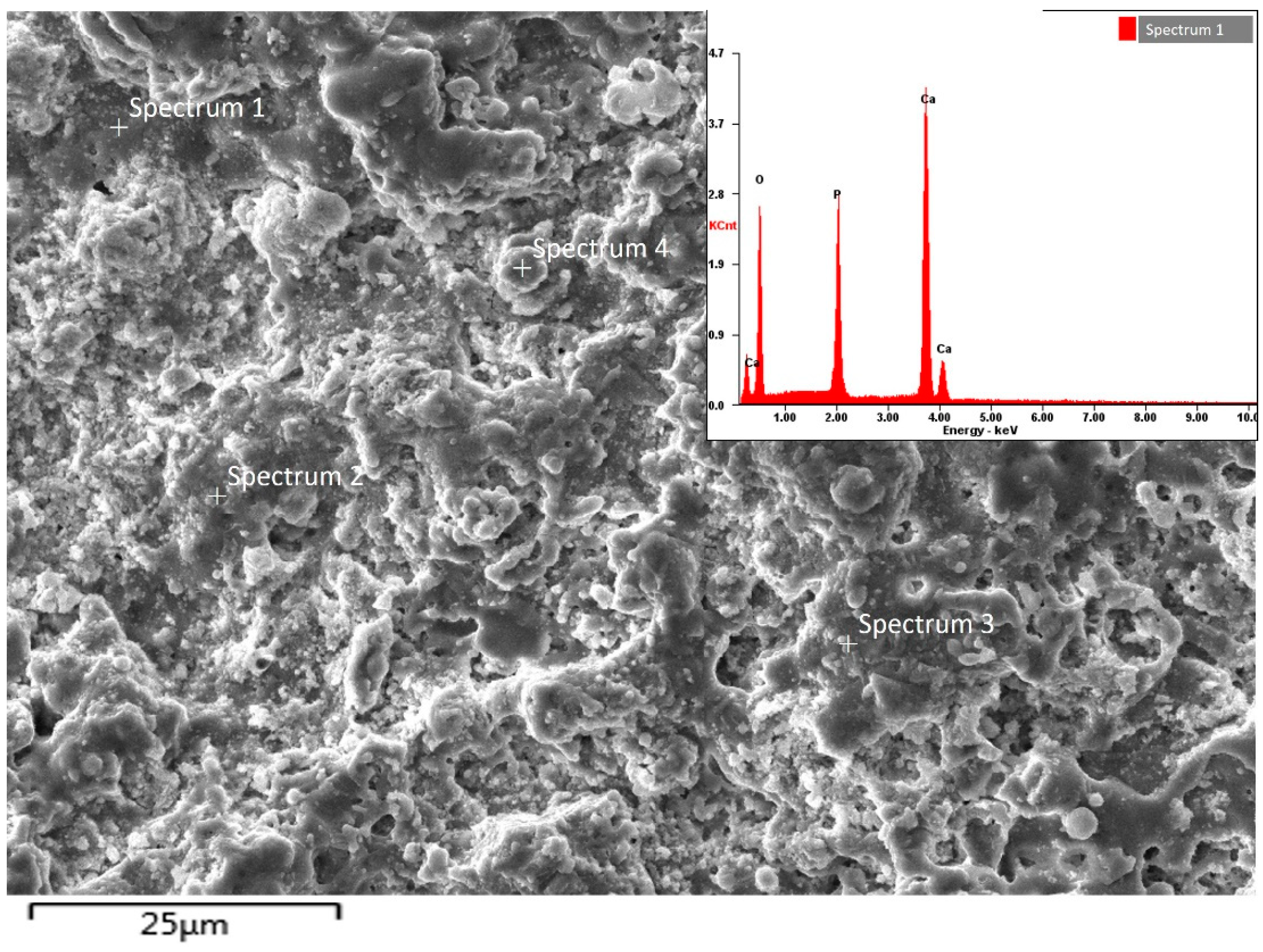
| Spectrum | Element | Weight | Atomic |
|---|---|---|---|
| Spectrum 1 | O | 46.31 | 55.74 |
| P | 19.18 | 17.29 | |
| Ca | 34.51 | 26.97 | |
| Spectrum 2 | O | 45.35 | 56.66 |
| P | 19.76 | 17.35 | |
| Ca | 34.89 | 25.99 | |
| Spectrum 3 | O | 46.98 | 55.98 |
| P | 19.76 | 16.88 | |
| Ca | 33.26 | 27.14 | |
| Spectrum 4 | O | 44.79 | 57.06 |
| P | 19.76 | 18.32 | |
| Ca | 34.45 | 24.62 |
Publisher’s Note: MDPI stays neutral with regard to jurisdictional claims in published maps and institutional affiliations. |
© 2021 by the authors. Licensee MDPI, Basel, Switzerland. This article is an open access article distributed under the terms and conditions of the Creative Commons Attribution (CC BY) license (https://creativecommons.org/licenses/by/4.0/).
Share and Cite
Rakhadilov, B.; Baizhan, D. Creation of Bioceramic Coatings on the Surface of Ti–6Al–4V Alloy by Plasma Electrolytic Oxidation Followed by Gas Detonation Spraying. Coatings 2021, 11, 1433. https://doi.org/10.3390/coatings11121433
Rakhadilov B, Baizhan D. Creation of Bioceramic Coatings on the Surface of Ti–6Al–4V Alloy by Plasma Electrolytic Oxidation Followed by Gas Detonation Spraying. Coatings. 2021; 11(12):1433. https://doi.org/10.3390/coatings11121433
Chicago/Turabian StyleRakhadilov, Bauyrzhan, and Daryn Baizhan. 2021. "Creation of Bioceramic Coatings on the Surface of Ti–6Al–4V Alloy by Plasma Electrolytic Oxidation Followed by Gas Detonation Spraying" Coatings 11, no. 12: 1433. https://doi.org/10.3390/coatings11121433
APA StyleRakhadilov, B., & Baizhan, D. (2021). Creation of Bioceramic Coatings on the Surface of Ti–6Al–4V Alloy by Plasma Electrolytic Oxidation Followed by Gas Detonation Spraying. Coatings, 11(12), 1433. https://doi.org/10.3390/coatings11121433