Article

A Study on the Laser Removal of Epoxy Coatings on SS400 Surface by Beam Scanning Patterns

1
Ocean Science and Technology School, Korea Maritime & Ocean University, Busan 49112, Korea
2
Innovative Manufacturing Technology Co., Ltd., Suwon 16675, Korea
3
Daewoo Shipbuilding & Marine Engineering Co., Ltd., Geoje 53302, Korea
4
Graduate School, Korea Maritime & Ocean University, Busan 49112, Korea
5
Division of Marine Engineering, Korea Maritime & Ocean University, Busan 49112, Korea
*
Author to whom correspondence should be addressed.
Coatings 2021, 11(12), 1510; https://doi.org/10.3390/coatings11121510
Submission received: 27 October 2021 / Revised: 30 November 2021 / Accepted: 6 December 2021 / Published: 8 December 2021
(This article belongs to the Special Issue Environmental Corrosion of Metals and Its Prevention)

Abstract

:
Shipyards are very interested in improving their working environment and resolving environmental pollution issues by replacing mechanical cleaning technologies used before and after painting processes with laser cleaning technology. Because epoxy paint is thickly coated, with a thickness of 200 μm or greater, it is difficult to remove using both laser cleaning and mechanical cleaning technologies. Therefore, this study tried to obtain effective cleaning results by controlling the process parameters when removing the thick epoxy coating using a Q-switching fiber laser cleaning system with an average power of 100 W developed by our research team. The pulse duration time of the laser is 150 ns. Additionally, in order to determine whether the cleaning was sufficient, the difference in laser-induced plume/plasma was compared. By controlling the beam scanning patterns, line overlap rate, and pulse overlap rate, it was possible to obtain effective cleaning results without introducing removal deviation. In addition, the NOP increased when the laser beam overlap rate increased. This increased the amount of heat input to the material and reduced the number of scans required to remove the epoxy paint. As a result of the plume/plasma analysis, less plume/plasma was generated as the paint was removed if the epoxy paint remained on the surface. On the other hand, when all of the paint was removed, a higher brightness of plume/plasma generated by evaporation of the bare metal was observed.

1. Introduction

Painting is a critical step in the shipbuilding process because it determines a ship’s corrosion and weather resistance as well as its aesthetics. Currently, shipyards use mechanical cleaning technologies such as blasting and grinding to clean the surfaces before and after painting. However, these technologies raise concerns about worker health and safety, as well as environmental pollution, as a result of the large number of abrasives and amount of fine dust discharged [1,2,3]. Additionally, they obstruct subsequent processes, extending the time required for product production. Laser cleaning technology is being lauded as a promising alternative for resolving this issue, and demand for it continues to grow year after year [4,5,6,7]. According to previous research, laser cleaning technology enables environmentally friendly work and significantly reduces process costs when compared to mechanical and chemical cleaning technologies [8,9,10,11,12].
Various types of paint are used on ships, depending on the intended use. Among them is epoxy paint, a typical anticorrosion paint. Because it is painted thicker than 200 μm on ships, its removal presents a significant challenge when using both laser cleaning and mechanical cleaning technologies. Before proceeding with this study, our researchers conducted a previous study to remove 200 μm of epoxy paint from the steel surface of ships using a fiber laser cleaning system with an average power of 100 W without a beam scanning pattern function [13,14,15,16,17]. As a result, it was possible to remove the paint from the metal surface, but there remained several problems to be solved in order to expand the cleaning area and obtain effective results. Based on such prior research, the current study developed and used a laser cleaning system with a beam scanning pattern function. Han et al. derived the optimal process parameters for the removal of epoxy-based paint from the surface of metal substrates and described the ablation mechanism of the cleaning process using an Nd: YAG laser [18]. Shamsujjoha et al. conducted a study to apply high-power laser cleaning technology to the shipbuilding industry [19,20]. The superiority of laser cleaning technology was demonstrated by comparing the sandblast with Nd: YAG laser cleaning. Schmidt et al. successfully removed epoxy resin coatings on concrete and metal surfaces using a high-power diode laser for nuclear decommissioning [21]. Zheng Kuang et al. demonstrated the effectiveness of LPS (laser paint stripping) for epoxy-paint removal using a nanosecond fiber laser system [22]. Litchfield et al. removed the crosslinked epoxide resin on the surface of an aluminum alloy, which is a lightweight material for automobiles, with a TEA CO2 laser. This could not be performed with conventional cleaning techniques [23]. Manoj Kumar et al. derived the threshold fluence and optimal scan speed for epoxy-paint removal using a TEA CO2 laser [24]. However, optimization of similar process parameters such as power, fluence, and scan speed was performed in most studies. In order to further expand the applicability of laser cleaning technology, it is necessary to control process parameters that have not been addressed in previous studies.
In this study, a Q-switching fiber laser cleaning system with an average power of 100 W that is suitable for small-surface-area cleaning was used to remove epoxy paint. The experiment was conducted by selecting the beam scanning patterns and the laser beam overlap rates as the main process parameters for laser cleaning. In particular, when laser cleaning using a scanner-type laser optical system, the beam scanning pattern must be considered because it is a major process parameter that greatly affects the performance and quality of the cleaned area. In addition, the plume/plasma behavior according to the material reacting with the laser beam was compared so that it could be immediately determined whether the epoxy coating was removed in the shipyard.

2. Materials and Methods

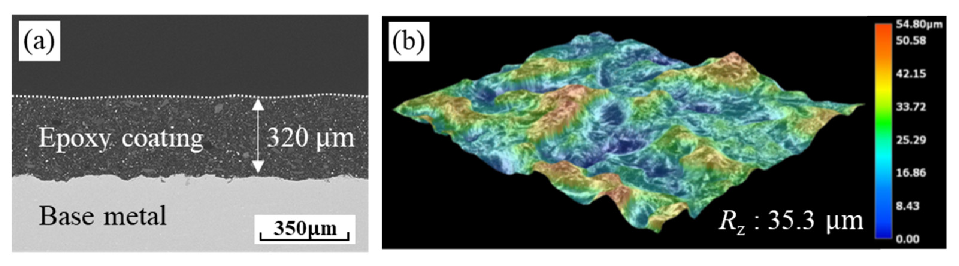
2.1. Experimental Materials

The SS400 coated with epoxy paint was used as the experimental material. Figure 1a shows the cross-sectional image of the specimen taken by SEM (Tescan, Brno, Czech Republic), and Figure 1b shows the topographic color distribution, as well as the roughness of the base metal before painting, taken with a KEYENCE VHX-7000 high-resolution 3D microscope (KEYENCE, Osaka, Japan). The thickness of the coating layer is about 320 μm. Additionally, to meet the pre-painting treatment standards, the base metal had a surface roughness of approximately 30–45 μm. In the shipbuilding industry, the ten-point average roughness (Rz) is used as a metric to evaluate the surface roughness of the base metal before painting. Therefore, in this study, the surface roughness was expressed using the same metric to provide more practical and better information to the shipbuilding industry site. The main components, properties, and thickness of the epoxy paint and the base metal are listed in Table 1.

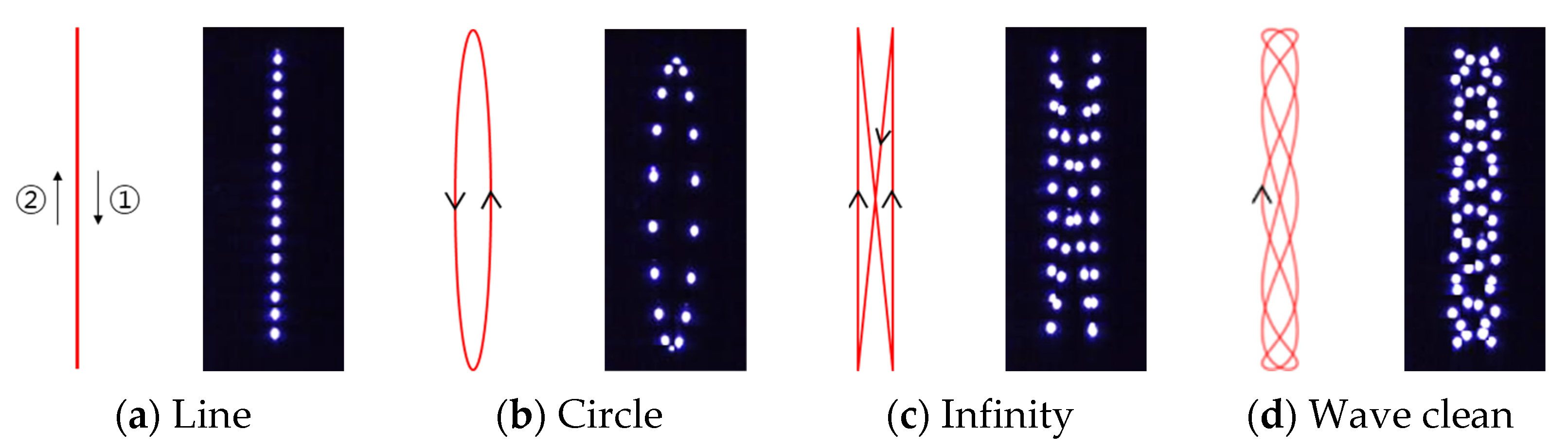
2.2. Laser Cleaning System and Experimental Approach

The laser used in this experiment is a Q-switching fiber laser with an average power of 100 W. The pulse duration time of the laser is 150 ns. Table 2 shows the fixed laser parameters used in the experiments. Figure 2 shows the experimental setup configured as a portable laser cleaning system. The portable laser head was fixed through a jig, and the specimen was placed on the X·Y stage. The laser beam is reflected by the galvano mirror controlled by the mechanical movement of the galvanometer in the laser optical head, and it irradiates along the beam scanning pattern to the specimen. The focal length for each position where the laser is irradiated was kept constant through the F-theta lens. The length of the laser beam scanning pattern in the X-axis direction is 50 mm, and when the stage is moved by 50 mm in the Y-axis direction, a 50 × 50 mm2 area is cleaned.
The laser cleaning process parameters selected for this study were the laser beam scanning pattern and overlap rate. Experiments were conducted in response to changes in these process parameters. Our researchers designed four beam scanning patterns: line, circle, infinity, and wave clean. Figure 3 shows the schematic diagram of the laser beam scanning direction according to the beam scanning pattern, as well as the photos synthesized at regular time intervals after the laser beam was moved by the 2D scanner (IMT, Suwon, Republic of Korea) and photographed with a high-speed camera (Photron, Tokyo, Japan). A schematic diagram of the experimental approach based on the laser beam overlap rate is depicted in Figure 4. As is evident, the laser beam is pulse-overlapped and line-overlapped for uniform cleaning. The pulse overlap rate (Rpo) is defined as a ratio in which laser beams overlap in the X-axis direction, and the line overlap rate (Rlo) is defined as a ratio in which laser passes overlap in the Y-axis direction. The pulse overlap rate is determined by the scan speed, and the line overlap rate is determined by the stage movement speed. Depending on the overlap rate, the scan speed is 2900–4800 mm/s, and the stage movement speed is 1.7–11 mm/s. The pulse overlap rate varied between 50% and 70%, while the line overlap rate varied between 20%, 50%, and 70%. First, with naked eyes checking each condition, the number of scans (Ns) was increased until the paint was removed. After that, XRD (Rigaku, Tokyo, Japan) component analysis was performed to verify the conditions for removing the paint.

2.3. Analysis Method

A high-speed camera was installed on the front of the laser cleaning equipment to analyze the scan path of the laser beam and the laser-induced plume/plasma, based on the beam scanning pattern. A frame per second (fps) of 7500, an exposure time (te) of 40 μs, and a photo size of 256 × 256 pixels were affixed as the shooting conditions for the high-speed camera. The morphology and the roughness of the laser-cleaned surface were observed through a KEYENCE VHX-7000 high-resolution 3D microscope (KEYENCE, Osaka, Japan), and cross-sectional images were taken through a Tescan MIRA-3 scanning electron microscope (Tescan, Brno, Czech). Finally, the surface composition of the specimen before and after laser cleaning was analyzed using RIGAKU’s SmartLab X-ray diffractometer (Rigaku, Tokyo, Japan). A typical powder diffraction technique was used. The X-ray source was a Cu K α , and the 2 θ range was 5° to 80°. PDXL integrated X-ray powder diffraction software from RIGAKU was used to detect the components of the peak.

3. Results and Discussion

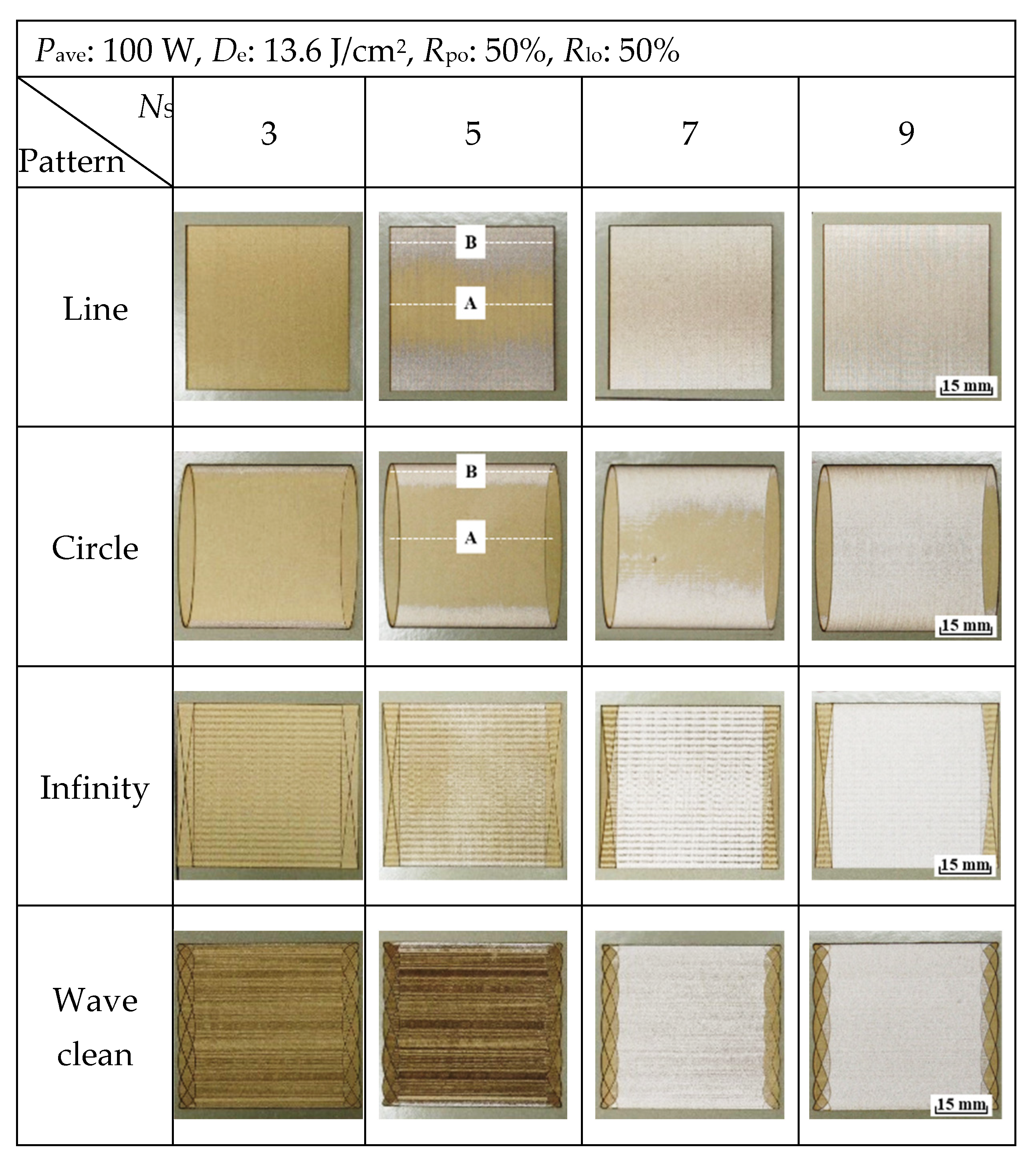
3.1. Effect of the Beam Scanning Pattern Types on the Laser Cleaning Performance

In this section, we analyze the effects of laser beam scanning patterns. Figure 4 shows the schematic diagram of the laser beam scanning direction according to the beam scanning pattern, as well as the photos synthesized at regular time intervals after the laser beam was moved by the 2D scanner and photographed with a high-speed camera. Figure 5 illustrates the laser-cleaned surfaces of epoxy-painted steel according to the number of scans when the laser beam scanning patterns shown in Figure 4 are used. The epoxy paint was gradually removed as the number of scans increased, and complete removal occurred between the 7th and the 9th scan. When the cleaning performance was assessed based on the beam scanning pattern, the paint appeared to be preferentially removed from the edge (B) in the case of the line and circle beam patterns. This is because the amount of heat input is greater at the edge (B) than at the center (A) due to the characteristics of the beam scanning pattern. Figure 6 shows the laser-induced plume/plasma images generated when line and circle beam patterns are used during laser cleaning. The image clearly shows that the intensity of the plume/plasma is greater at the edge (B). In the case of the line beam pattern, as the stage and the laser beam move simultaneously, the overlap of the laser beam increases at the edge. In the case of the circle beam pattern, when the laser beam follows a curve at the edge, the amount of heat input to the material increases as the laser beam overlaps more here than at the center. As a result, the plume/plasma intensity and the resultant amount of paint that is removed both vary according to the area. On the other hand, when the infinity and wave clean beam patterns are used, the paint is removed uniformly without any deviation for each area.
For the surface treatment of steel for ships, a larger cleaning area is required compared to that for cleaning artworks, semiconductors, and electrical/electronic components [19,20]. In addition, our researchers confirmed that the laser cleaning performance was not uniform during laser cleaning using the line beam, which is generally used. The same was true for the circle beam. However, by designing the scan path of the laser beam in a complicated manner through the (c) infinity and (d) wave clean beam patterns in Figure 3, effective cleaning results that do not cause removal deviation at the edges were obtained. As a result, it was found that not only the number of scans but also the scan path of the laser beam has a great influence on the laser cleaning results.
After laser cleaning, XRD analysis was performed on the cleaned surface to confirm the removal of the epoxy paint. Figure 7 shows the XRD analysis results of the laser-cleaned surface with a wave clean beam pattern. Pyrophyllite and barite were detected as components of the epoxy paint. It can be confirmed that the component of the base material (Fe) is detected after the component of the paint is completely removed when the number of scans is seven or higher. This shows that the epoxy paint on the steel surface can be effectively removed by laser cleaning technology.

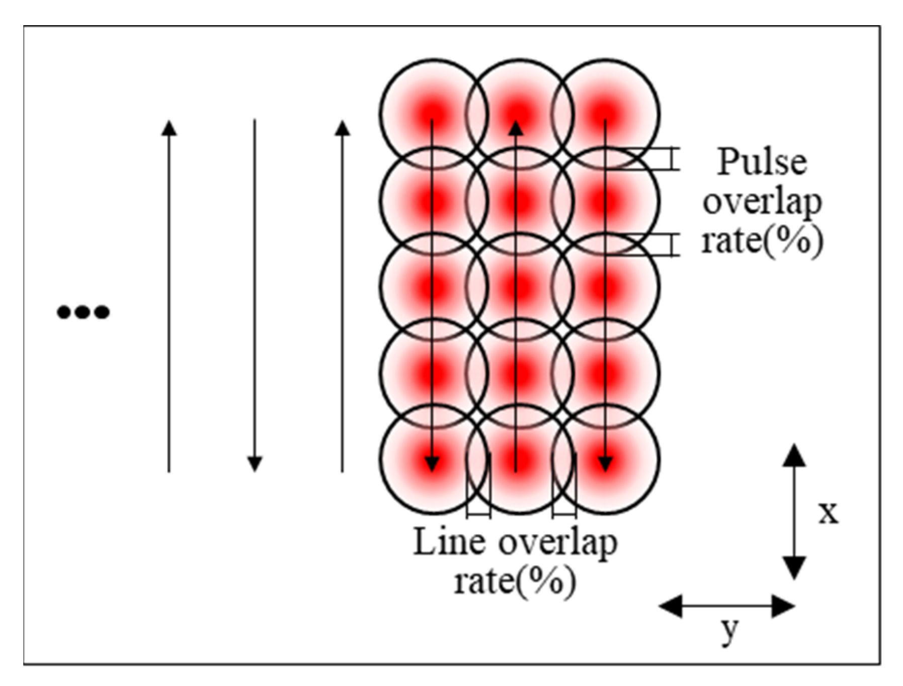
3.2. Effect of the Laser Beam Overlap Rates on the Laser Cleaning Performance

In the laser cleaning process for paint removal on the steel surface, laser beam overlap is an important process parameter that must be considered since it greatly affects heat input. Figure 8 shows the number of scans to remove epoxy paint according to the pulse and line overlap rates when the wave clean beam pattern is used. In this study, the pulse overlap rate varied between 50% and 70% while the line overlap rate varied between 20%, 50%, and 70%. When the pulse and line overlap rate were set to the minimum, 50% and 20%, respectively, all of the 320 μm thick epoxy paint was removed during the 13 scans that were performed. After that, the number of scans for removing the epoxy paint decreases even when the overlapping rate is increased. This is because the amount of heat input irradiated to the material increases as the overlap rate increases. In laser cleaning using a pulse laser, the overlap rate R is obtained through Equation (1) [25]. Here, v is the scan speed (mm/s), d is the beam diameter (mm), and f is the pulse frequency (Hz).
R = [ 1 ( v d × f ) ] × 100
Therefore, the scan speed decreases as the overlap rate increases. The number of pulses in a spot (NOP) is derived on this basis. The NOP is calculated by Equation (2) [26].
NOP = d v f
When the overlap ratio is 20%, the NOP is about 1; when it is 50%, the NOP is about 2; when it is 70%, the NOP is about 3. As a result, as the overlap rate increases, the number of laser pulses irradiated per unit area increases, thereby increasing the amount of heat input.
The mechanism of the laser cleaning process can be divided into a quantum process that does not involve heat and a thermal process. The mechanism of the quantum process is based on removal processing by laser shock waves [4,27]. For removal processing, ultra-short pulse duration times of ps and fs and high peak powers of GW and MW are required [4,27]. This mechanism is mainly applied in the electric and semiconductor industries that do not involve heat. On the other hand, since a high-speed and large-area process is required for paint removal on the surface of the steel during shipbuilding, it is efficient to use a thermal process mechanism using a laser heat source in parallel with a quantum process. In this laser cleaning process, as can be seen from the experimental results above, the laser cleaning performance may be significantly affected by the difference in the amount of heat input according to the laser beam overlap rate.
After laser cleaning, the surface roughness and the microstructure of the cleaned area were analyzed to identify the damage to the base metal and the thermal effect on the substrate. Figure 9 shows a micrographic and cross-sectional image of the laser-cleaned surface according to the line overlap rate and the number of scans when the pulse overlap rate is 50%. First, when the epoxy paint remains and when the line overlap rate is 20% and 50%, a rough cleaned surface in which a wave clean beam pattern appears is observed. When the line overlap rate is 70%, a relatively smooth surface can be confirmed due to a decrease in the distance between the lines. When all the paint is removed, the base metal underneath the coating is exposed. Figure 10 shows the surface roughness values of the specimen shown in Figure 9. When the laser is irradiated to the specimen, evaporation of the epoxy coating occurs, and the unevenness of the surface increases. Therefore, the surface roughness value increases compared to what it was before laser cleaning. In particular, when the line overlap rate is 50%, since the laser beam is repeatedly irradiated to the same location during laser scanning, a deep valley is formed, and the surface roughness value is at its highest. After the paint is completely removed, the roughness of the cleaned surface is similar to that of the base metal. This is because only the paint is selectively evaporated and removed without damage to the base metal due to the difference in properties between the epoxy paint and the base metal. Even when the pulse overlap rate is 70%, similar trends can be confirmed in the conditions of paint residual and removal, as shown in Figure 10, with a pulse overlap rate of 50%. However, as the overlap rate increases, the valleys formed on the surface collapse once the laser is scanned, resulting in a relatively low roughness value. Figure 11 shows the microstructure of the laser-cleaned specimen before and after the intervention, as well as that of the base metal. Compared with before cleaning, almost no molten layer is observed on the surface of the laser-cleaned specimen. In addition, there is no change in its grain size compared to that of the base metal in the depth direction from the surface. As a result, no damage to the base metal was observed after laser cleaning, and a laser-cleaned area free from thermal effects such as heat-affected zones and melted layers was obtained.

3.3. Laser-Induced Plume/Plasma Behavior Analysis

In this section, we compare the plume/plasma behavior according to the material reacting with the laser beam to confirm the removal of the epoxy paint. Figure 12 shows the laser-induced plume/plasma images under the paint residual and removal conditions, respectively, during laser cleaning with a wave clean beam pattern. As illustrated in Figure 12a, the epoxy paint absorbs the laser energy that is irradiated according to the beam scanning pattern and excites it while undergoing evaporation. On the other hand, when the paint is completely removed and the surface of the base metal is exposed, a high intensity plume/plasma generated by the evaporation of the metal is observed in Figure 12b.
Figure 13 illustrates the laser-induced plume/plasma images captured with a high-speed camera in the presence of paint residue. The plume/plasma behavior of the box area in the schematic diagram of the beam scanning pattern was analyzed at regular time intervals. With the change in time, it can be observed that the laser beam is irradiated to the specimen while changing its position along the scan path of the wave beam pattern. Additionally, the behavior of the plume/plasma was observed to be stable. This demonstrates that the energy emitted by the laser is readily absorbed by the epoxy paint without much resistance due to its low melting and boiling points, as can be seen in Table 1, causing the paint to vaporize and excite. As a result, since there was a significant difference in the plume/plasma behavior depending on the material that reacts with the laser, it was possible to confirm whether the epoxy paint was removed by laser cleaning just by visually observing the plume/plasma behavior.
In subsequent research, we plan to closely examine the differences in the dynamic behavior and the color change of plume/plasma according to process parameters, types of paints, and main components.

4. Conclusions

The purpose of this study was to determine the cleaning performance of epoxy paint according to process parameters using a Q-switching fiber laser cleaning system with an average power of 100 W that is suitable for small surface area cleaning, which was developed by our team. As a result of the analysis, the following conclusions were drawn.
(1)
The amount of heat input increased at the edge in the case of the line and circle beam patterns, resulting in a removal deviation between the center and the edge. On the other hand, in the case of the infinity and wave clean beam patterns, by designing the scan path of the laser beam in a complicated manner, it was possible to derive effective cleaning results in which removal deviations by area did not occur. As a result, it was found that not only the process parameters but also the scan path of the laser beam has a great influence on the laser cleaning results.
(2)
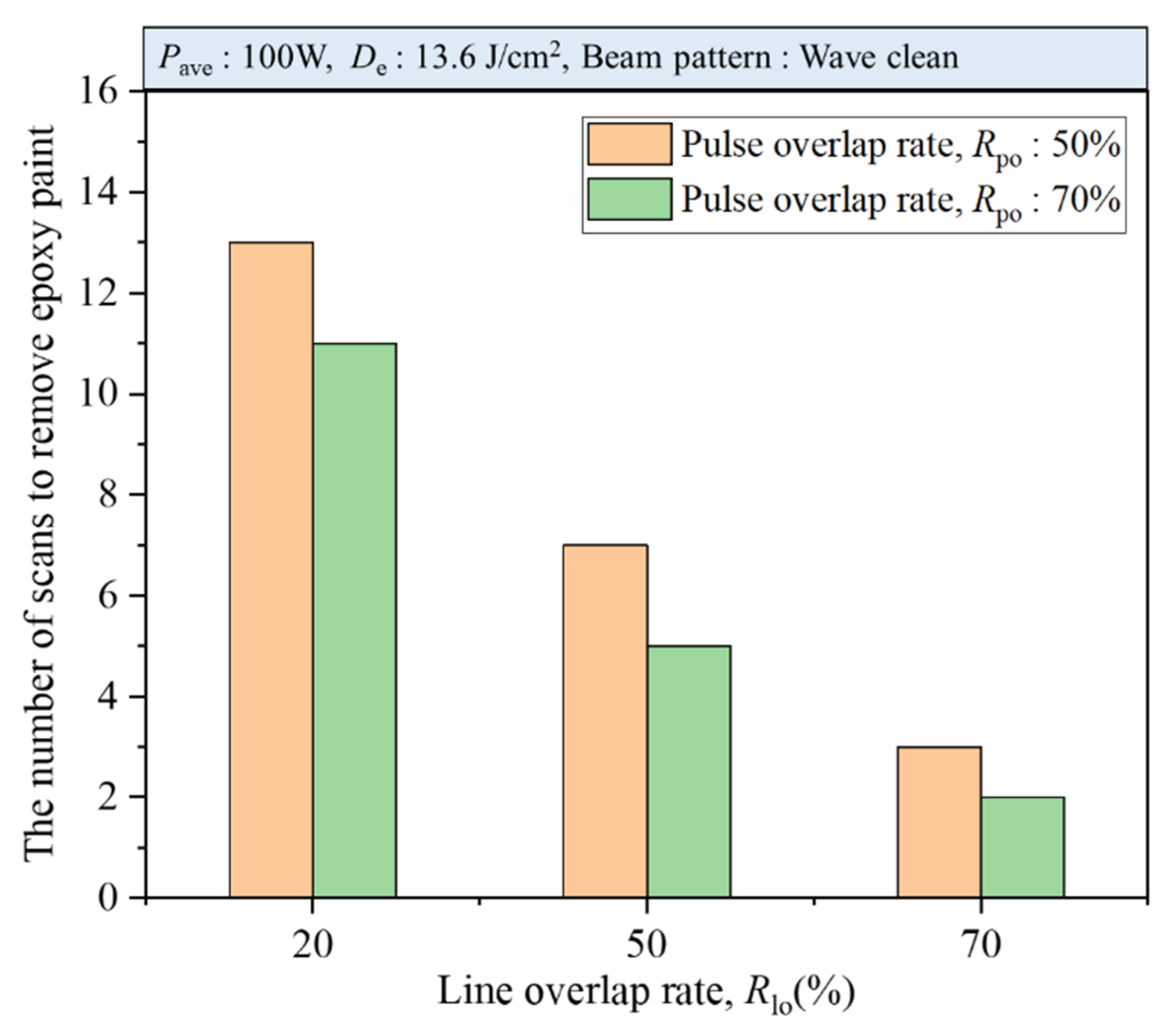
The number of pulses in a spot (NOP) increased when the laser beam overlap rate increased. This increased the amount of heat input to the material and reduced the number of scans required to remove the epoxy paint.
(3)
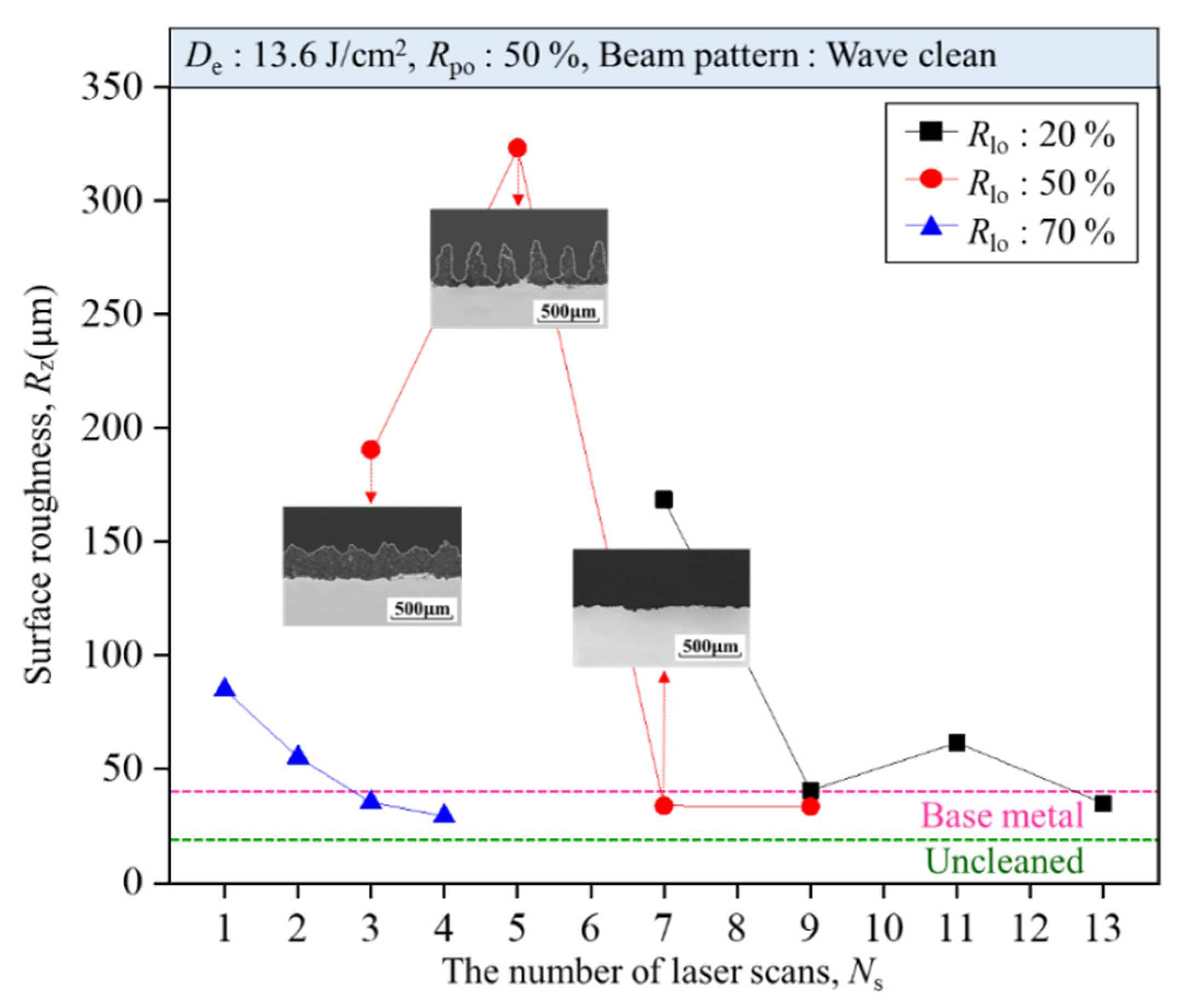
As a result of analyzing the surface roughness and the microstructure of the laser-cleaned area, the roughness of the cleaned specimen and of the base metal was similar after the paint was completely removed. This is because the paint was selectively evaporated and removed due to the difference in properties between the base metal and the paint. In addition, no heat-affected zone or melted layer was observed in the laser-cleaned surface. That is, after laser cleaning, it was possible to obtain a cleaned area without damage to the base metal and with no thermal effect.
(4)
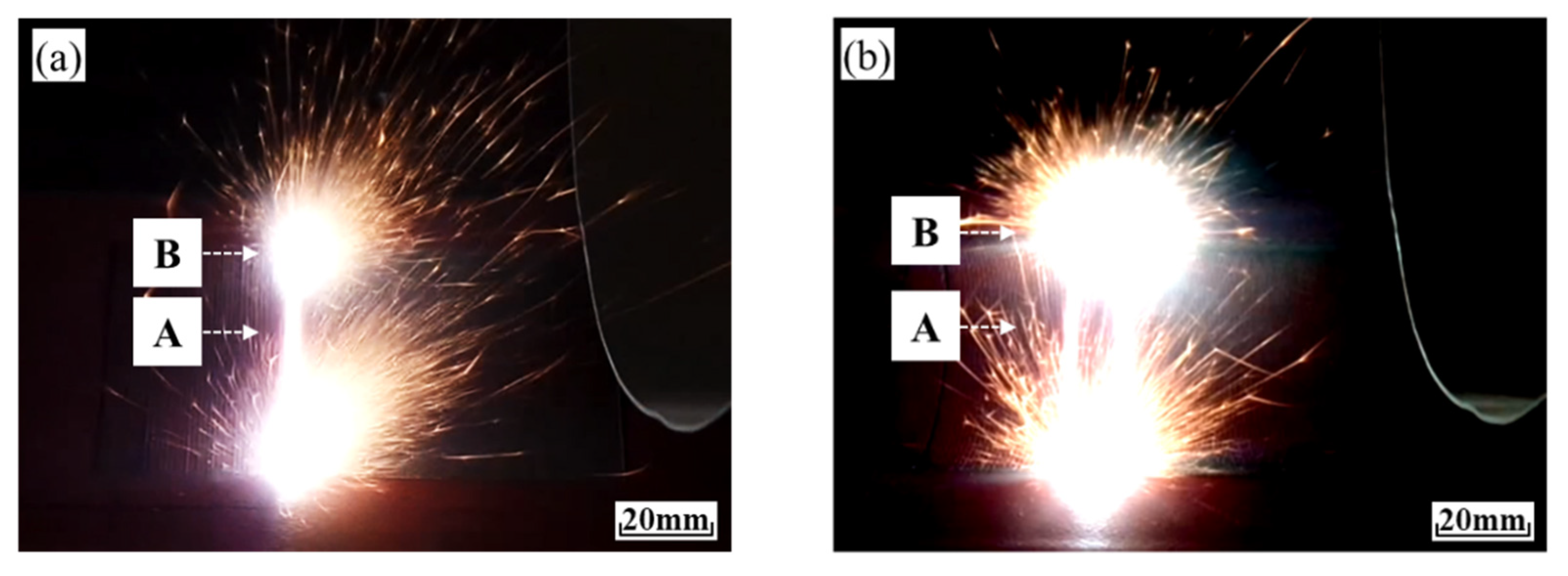
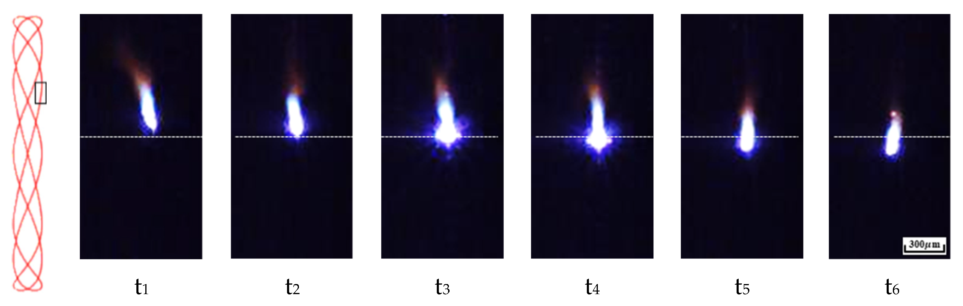
As a result of laser-induced plume/plasma analysis, less plume/plasma was generated as the paint was removed if the epoxy paint remained on the surface. On the other hand, when all of the paint was removed, a plume/plasma of higher brightness generated by evaporation of the bare metal was observed. As a result, it was possible to determine whether cleaning was sufficient by comparing the difference in plume/plasma generated during laser cleaning.
(5)
This study not only reported the effect of beam scanning pattern during laser cleaning, but it also improved cleaning effect and performance during paint removal in a small surface area. Through this, it is expected to change the paradigm of the laser cleaning process with the conventionally used line beam.

Author Contributions

Conceptualization, J.-D.K. and J.-E.K.; Methodology, J.-D.K. and J.-E.K.; Validation, J.-D.K. and J.-E.K.; Investigation, J.-E.K., J.-M.L., J.-H.J.; Resources, J.-H.H., J.-M.L.; Writing—Original Draft Preparation, J.-E.K.; Writing—Review & Editing, J.-D.K.; Visualization, J.-E.K.; Supervision, J.-D.K.; Project Administration, J.-D.K.; Funding Acquisition, J.-D.K. All authors have read and agreed to the published version of the manuscript.

Funding

This research received no external funding.

Institutional Review Board Statement

Not applicable.

Informed Consent Statement

Not applicable.

Data Availability Statement

Not applicable.

Conflicts of Interest

The authors declare no conflict of interest.

References

  1. Kim, J.D.; Kim, J.E.; Song, M.K.; Lee, J.M. A Fundamental Study on the High-Power Fiber Laser Cleaning for Removing the Multi-Layer Coating. J. Weld. Join. 2020, 38, 563–568. [Google Scholar] [CrossRef]
  2. D’Addona, D.M.; Genna, S.; Giordano, A.; Leone, D.M.C.; Nele, L. Laser Ablation of Primer During the Welding Process of Iron Plate for Shipbuilding Industry. Procedia CIRP 2015, 33, 464–469. [Google Scholar] [CrossRef]
  3. Chen, G.X.; Kwee, T.J.; Tan, K.P.; Choo, Y.S.; Hong, M.H. High-Power Fibre Laser Cleaning for Green Ship-building. J. Laser Micro/Nanoeng. 2012, 7, 249–253. [Google Scholar] [CrossRef] [Green Version]
  4. Razaba, M.K.A.A.; Noorb, A.M.; Jaafarc, M.S.; Abdullahb, N.H.; Suhaimid, F.M.; Mohamedb, M.; Adame, N.; Yusuf, N.A.A.N. A review of incorporating Nd:YAG laser cleaning principal in automotive industry. J. Radiat. Res. Appl. Sci. 2018, 11, 393–402. [Google Scholar] [CrossRef] [Green Version]
  5. Marimuthu, S.; Sezer, H.K.; Kamara, A.M. Applications of Laser Cleaning Process in High Value Manufacturing Industries. Dev. Surf. Contam. Clean. 2019, 11, 251–288. [Google Scholar]
  6. Tang, Q.H.; Zhou, D.; Wang, Y.L.; Liu, G.F. Laser cleaning of sulfide scale on compressor impeller blade. Appl. Surf. Sci. 2015, 355, 334–340. [Google Scholar] [CrossRef]
  7. Kim, J.-E.; Kim, J.-D. A study on the removal of paint and oxide layer on the steel surface by laser beam scanning method. Int. J. Mod. Phys. B 2021, 2021, 2140006. [Google Scholar] [CrossRef]
  8. Turner, M.W.; Crouse, P.L.; Li, L.; Smith, A.J.E. Investigation into CO2 laser cleaning of titanium alloys for gas-turbine component manufacture. Appl. Surf. Sci. 2006, 252, 4798–4802. [Google Scholar] [CrossRef]
  9. Zhu, G.; Wang, S.; Cheng, W.; Ren, Y.; Wen, D. Corrosion and wear performance of aircraft skin after laser cleaning. Opt. Laser Technol. 2020, 132, 1–14. [Google Scholar] [CrossRef]
  10. AlShaer, A.W.; Li, L.; Mistry, A. The effects of short pulse laser surface cleaning on porosity formation and reduction in laser welding of aluminium alloy for automotive component manufacture. Opt. Laser Technol. 2014, 64, 162–171. [Google Scholar] [CrossRef]
  11. Zhu, G.; Wang, S.; Cheng, W.; Wang, G.; Liu, W.; Ren, Y. Investigation on the Surface Properties of 5A12 Aluminum Alloy after Nd: YAG Laser Cleaning. Coatings 2019, 9, 578. [Google Scholar] [CrossRef] [Green Version]
  12. Hu, C.; He, G.; Chen, J.; Fang, Z.; Yang, Z.; Zhang, Z. Research on Cleaning Mechanism of Anti-Erosion Coating Based on Thermal and Force Effects of Laser Shock. Coatings 2020, 10, 638. [Google Scholar] [CrossRef]
  13. Kim, J.E.; Song, M.K.; Lee, J.M.; Hyun, J.H.; Kim, J.D. A Study on the Effect of Overlap Rate on Laser Beam Cleaning Characteristics while Cleaning Paint Using a Low Power Pulsed Laser(I). J. Weld. Join. 2019, 37, 435–440. [Google Scholar] [CrossRef] [Green Version]
  14. Kim, J.E.; Song, M.K.; Lee, J.M.; Hyun, J.H.; Kim, J.D. A Study on the Effect of Overlap Rate on Laser Beam Cleaning Characteristics while Cleaning Paint Using a Low Power Pulsed Laser(II). J. Weld. Join. 2019, 37, 441–447. [Google Scholar] [CrossRef]
  15. Kim, J.D.; Kim, J.E.; Song, M.K.; Lee, J.M.; Han, M.S. A Study on Laser Cleaning Efficiency of Epoxy Paint According to Process Parameters (I). Trans. Korean Soc. Mech. Eng. A 2020, 44, 199–205. [Google Scholar] [CrossRef]
  16. Kim, J.D.; Kim, J.E.; Song, M.K.; Lee, J.M.; Han, M.S. A Study on Laser Cleaning Efficiency of Epoxy Paint According to Process Parameters (II). Trans. Korean Soc. Mech. Eng. A 2020, 44, 207–212. [Google Scholar] [CrossRef]
  17. Kim, J.E.; Han, M.S.; Kim, J.D. Removal characteristics of shop-primer paint by laser energy density in Q-switching fiber laser cleaning. Mod. Phys. Lett. B 2020, 34, 1–6. [Google Scholar] [CrossRef]
  18. Han, J.; Cui, X.; Wang, S.; Feng, G.; Deng, G.; Hu, R. Laser effects based optimal laser parameter identifications for paint removal from metal substrate at 1064 nm: A multi-pulse model. J. Mod. Opt. 2017, 64, 1947–1959. [Google Scholar] [CrossRef]
  19. Shamsujjoha, M.; Agnew, S.R.; Melia, M.A.; Brooks, J.R.; Tyler, T.J.; Fitz-Gerald, J.M. Effects of laser ablation coating removal (LACR) on a steel substrate: Part 1: Surface profile, microstructure, hardness, and adhesion. Surf. Coat. Technol. 2015, 281, 193–205. [Google Scholar] [CrossRef]
  20. Shamsujjoha, M.; Agnew, S.R.; Brooks, J.R.; Tyler, T.J.; Fitz-Gerald, J.M. Effects of laser ablation coating removal (LACR) on a steel substrate: Part 2: Residual stress and fatigue. Surf. Coat. Technol. 2015, 281, 206–214. [Google Scholar] [CrossRef]
  21. Schmidt, M.J.J.; Li, L.; Spencer, J.T. An investigation into the feasibility and characteristics of using a 2.5 kW high power diode laser for paint stripping. J. Mater. Process. Technol. 2003, 138, 109–115. [Google Scholar] [CrossRef]
  22. Kuang, Z.; Guo, W.; Li, J.; Jin, Y.; Qian, D.; Ouyang, J.; Fu, L.; Fearon, E.; Hardacre, R.; Liu, Z.; et al. Nanosecond fibre laser paint stripping with suppression of flames and sparks. J. Mater. Process. Technol. 2019, 266, 474–483. [Google Scholar] [CrossRef]
  23. Litchfield, R.E.; Critchlow, G.W.; Wilson, S. Surface cleaning technologies for the removal of crosslinked epoxide resin. Int. J. Adhes. Adhes. 2006, 26, 295–303. [Google Scholar] [CrossRef] [Green Version]
  24. Kmar, M.; Bhargava, P.; Biswas, A.K.; Sahu, S.; Mandloi, V.; Ittoop, M.O.; Khattak, B.Q.; Tiwari, M.K.; Kukreja, L.M. Epoxy-paint stripping using TEA CO2 laser: Determination of threshold fluence and the process parameters. Opt. Laser Technol. 2013, 46, 29–36. [Google Scholar] [CrossRef]
  25. Taheri, M.; Razavi, M.; Kashani-Bozorg, S.F.; Torkamany, M.J. Relationship between solidification and liquationcracks in the joining of GTD-111 nickel-basedsuperalloy by Nd:YAG pulsed-laser weld. J. Mater. Res. Technol. 2021, 15, 5635–5649. [Google Scholar] [CrossRef]
  26. See, T.L.; Liu, Z.; Cheetham, S.; Dilworth, S.; Li, L. Laser abrading of carbon fibre reinforced composite for improving paint adhesion. Appl. Phys. A 2014, 117, 1045–1054. [Google Scholar] [CrossRef]
  27. Liu, Y.; Liu, W.; Zhang, D.; Tian, Z.; Sun, X.; Wei, Z. Experimental investigations into cleaning mechanism of ship shell plant surface involved in dry laser cleaning by controlling laser power. Appl. Phys. A Mater. Sci. Process. 2020, 126, 866. [Google Scholar] [CrossRef]
Figure 1. (a) The cross-sectional image of the specimen and (b) the topographic color distribution and roughness of the base metal before painting.
Coatings 11 01510 g001
Figure 2. Experimental setup for the laser cleaning experiment using a portable fiber laser cleaning system.
Coatings 11 01510 g002
Figure 3. Schematic of the laser beam scanning direction and high-speed camera photography based on beam scanning patterns; (a) Line, (b) Circle, (c) Infinity, (d) Wave clean.
Coatings 11 01510 g003
Figure 4. Schematic of the experimental approach based on the laser beam overlap rate.
Coatings 11 01510 g004
Figure 5. Laser-cleaned surfaces of epoxy-painted steel with the laser beam scanning patterns.
Coatings 11 01510 g005
Figure 6. Laser-induced plume/plasma images according to the beam scanning patterns during the laser cleaning process when using (a) a line beam pattern, and (b) a circle beam pattern.
Coatings 11 01510 g006
Figure 7. XRD analysis results of the specimen before and after laser cleaning using a wave clean beam pattern.
Coatings 11 01510 g007
Figure 8. The number of scans to remove epoxy paint according to the laser beam overlap rates.
Coatings 11 01510 g008
Figure 9. Micrography and cross-section of the laser-cleaned surfaces at a pulse overlap rate of 50%.
Coatings 11 01510 g009
Figure 10. Variation of roughness in the laser-cleaned surfaces according to the line overlap rates.
Coatings 11 01510 g010
Figure 11. Comparison of microstructure of the laser-cleaned specimen (a) before and (b) after laser cleaning and (c) that of the base metal.
Coatings 11 01510 g011
Figure 12. Laser-induced plume/plasma images under the (a) paint residual and (b) removal conditions during laser cleaning with wave clean beam pattern.
Coatings 11 01510 g012
Figure 13. Laser-induced plume/plasma images taken with a high-speed camera in the presence of the paint residue.
Coatings 11 01510 g013
Table 1. Properties of the experimental materials.
PropertyMain ComponentMelting Point * (°C)Boiling Point * (°C)Thickness (mm)
Material
EpoxyBisphenol epoxy A1582200.32
SS400Fe153828623
* The melting and boiling points mentioned here are the values of the main components of each material.
Table 2. The fixed laser parameters for the laser cleaning experiment.
Laser ParameterValue
Laser typeQ-switching fiber laser
Average power, Pave100 W
Wave length1070 ± 5 nm
Energy density(fluence), De13.6 J/cm2
Pulse duration time150 ns
Pulse frequency, f100 kHz
Beam diameter, d97 µm
Publisher’s Note: MDPI stays neutral with regard to jurisdictional claims in published maps and institutional affiliations.

