Article

Plasma Enhanced Atomic Layer Deposition of Ruthenium Films Using Ru(EtCp)2 Precursor

Valiev Institute of Physics and Technology of RAS, Nakhimovsky av. 36/1, 117218 Moscow, Russia
*
Author to whom correspondence should be addressed.
Coatings 2021, 11(2), 117; https://doi.org/10.3390/coatings11020117
Submission received: 19 December 2020 / Revised: 14 January 2021 / Accepted: 15 January 2021 / Published: 21 January 2021

Abstract

:
Ruthenium thin films were deposited by plasma-enhanced atomic layer deposition (PEALD) technology using Ru(EtCp)2 and oxygen plasma on the modified surface of silicon and SiO2/Si substrates. The crystal structure, chemical composition, and morphology of films were characterized by grazing incidence XRD (GXRD), secondary ion mass spectrometry (SIMS), and atomic force microscopy (AFM) techniques, respectively. It was found that the mechanism of film growth depends crucially on the substrate temperature. The GXRD and SIMS analysis show that at substrate temperature T = 375 °C, an abrupt change in surface reaction mechanisms occurs, leading to the changing in film composition from RuO2 at low temperatures to pure Ru film at higher temperatures. It was confirmed by electrical resistivity measurements for Ru-based films. Mechanical stress in the films was also analyzed, and it was suggested that this factor increases the surface roughness of growing Ru films. The lowest surface roughness ~1.5 nm was achieved with a film thickness of 29 nm using SiO2/Si-substrate for deposition at 375 °C. The measured resistivity of Ru film is 18–19 µOhm·cm (as deposited).

1. Introduction

Thin ruthenium films are highly demanded in a wide range of applications. Ruthenium is a leading candidate for next-generation integrated circuit (IC) interconnection [1,2,3,4], as an ultra-thin layer of ruthenium has an electrical conductivity higher than other competing metals [5], does not require special barrier layers, and can be deposited in narrow trenches by atomic deposition (ALD) [6,7]. Ruthenium is also a promising candidate for the electrodes of the dynamic random-access memory (DRAM) capacitors [8], gate electrodes in metal oxide semiconductor transistors (MOSFETs) [9], and high conductive coating for MEMS devices [10,11]. It is also widely used in heterogeneous catalysis [12]. For example, it acts as a catalyst in Fischer Tropsch [13] and ammonia decomposition reactions [14,15]. Thin ruthenium films are also essential for soft X-ray [16,17,18] and extreme ultraviolet (EUV) optics [18,19]. To a large extent, considerable interest in ruthenium can be explained by comparably low prices for this noble metal.
There are a few articles about the chemical vapor deposition (CVD) of ruthenium [20,21,22,23,24]. However, the most interest is concentrated on conformal thin and ultrathin Ru and RuO2 films, and the best way to get them is an atomic layer deposition (ALD) technique [25,26,27,28,29,30,31]. A lot of organometallic precursors have been developed for ruthenium deposition [32]. The most frequently used precursors are bis(cyclopentadienyl)ruthenium(II) (or RuCp2) [25,33] and bis(ethylcyclopentadienyl)ruthenium(II) (or Ru(EtCp)2) [8,18,34]. Ru(EtCp)2 is a relatively inexpensive, commercially available liquid precursor. Thermal and plasma-enhanced ALD (PEALD) processes have been presented for this precursor. Moreover, a wide variety of co-reactants can be selected for Ru(EtCp)2, such as O2 [6,33], O3 gases [8], and NH3 plasma [33]. Using Ru(EtCp)2, it is possible to get high density (12.3 g·cm−3) [18] ruthenium thin films with low surface roughness (0.9 nm) and low resistivity (up to 16 µOhm·cm) [33].
This article presents the investigations of structural and electrical properties of ruthenium-based thin films deposited by PEALD on silicon and silicon dioxide in the extended range of substrate temperature (200–400 °C). The influence of post-process annealing at 400 °C on film properties is also analyzed. The maximum process temperature of 400 °C seems to be the typical thermal budget for most applications.

2. Experimental

Atomic-layer deposition of films was carried out on the substrates of p-type boron-doped monocrystalline silicon wafers (10 Ohm·cm) with a diameter of 100 mm, a thickness of 460 μm, with a surface orientation of (100). In other sets of experiments, Ru-based films were also deposited on the same silicon wafers with a preliminary deposited by PECVD SiO2 layer of 300 nm thick for electrical measurements and comparison of PEALD growth features with deposition on a bare silicon surface.
The deposition process was carried out on a commercial FlexAl system (Oxford Instruments Plasma Technology, Yatton, UK) in a plasma-enhanced mode using a 13.56 MHz ICP remote plasma source. The chamber was evacuated with the turbo-molecular pump to a base pressure of 1.2 × 10⁻⁶ Torr.
The process was performed in the range of growth temperature of 200–400 °C using an alternating dosage of Ru(EtCp)2 and O2 plasma into the chamber. Argon and oxygen used in the process were 99.9999% quality grade. Chamber walls and precursor feeding pipes, as well as the vacuum system, were pre-heated to 100–120 °C to prevent precursor condensation. The chamber pressure was kept at 65 mTorr during the plasma step in the PEALD cycle. Ru(EtCp)2 was contained in a bubbler, which was pre-heated to 70 °C. Its saturated vapor was delivered to the reactor chamber by argon carrier gas at the flow rate of 150 sccm.
One deposition cycle of PEALD for Ru-films consisted of six steps: (i) dosage of Ru(EtCp)2 during 2 s; (ii) pump out the chamber during 1 s; (iii) purge pulse with 150 sccm of Ar for 4 s; (iv) 2 s step of oxygen pressure stabilization in the chamber; (v) O2 plasma ignition and exposure during 1 s, and (vi) another chamber purge with 150 sccm of Ar for 4 s. The remote ICP plasma was powered at 75 Watt with 60 sccm of oxygen flow.
The bare silicon wafer with native oxide or silicon oxide surface ruthenium growth started from the formation of random nuclei instead of normal monolayer-by-monolayer mode, and therefore a growing film had no integrity at the beginning of growth and large roughness after the process was complete. Since it is known [33] that the introduction of sub-layers of transition metal nitrides can significantly improve nucleation of Ru, the possibilities of using the underlying sub-1 nm TiN and TaN layers were previously investigated. The material of the sub-layers, their thickness (as minimal as possible), and the resulting roughness of the layers were optimized. It was found that the best nucleation condition for Ru film at the first PEALD cycle is provided by a surface with tantalum nitride film interlayer (IL) applied in the same chamber without breaking the vacuum [35]. The dependence of the stack Ru/IL TaN roughness on the thickness of TaN sub-layer was separately investigated. The tantalum nitride layer obtained at five cycles is sufficient enough for good Ru-nucleation, and the resulting roughness of 0.4 nm was obtained, which is comparable to the substrate surface roughness. A further increase in the thickness of the tantalum nitride interlayer leads to a rise in the surface roughness.
In this study, PEALD of tantalum nitride IL employed organometallic precursor tertiary-butylimido-tris-(diethylamino)-tantalum (TBTDET) with the linear formula Ta[N(C2H5)2]3[=NC(CH3)3]. The bubbler was heated to a temperature of 70 °C. It is known that plasma-enhanced ALD of tantalum nitrides from organometallic precursors makes it possible to obtain a range of nitrides of different stoichiometry and conductivity (from metallic TaN to dielectric Ta3N5) [36,37]. Our goal was to deposit the conducting seed layer. Therefore, the optimization of the PEALD reaction of TBTDET with hydrogen plasma was aimed at obtaining the stoichiometric composition of sub-layer TaN. Increasing the plasma exposure time for adsorbed TBTDET provides the decline of the specific film resistance due to the removal of the excess of nitrogen; however, the ALD cycle duration significantly increases. The resistivity of tantalum nitride obtained in optimized PEALD process was about 2–3 mΩ·cm (measured by the four probe method) that correspond with literature data [38].
Summarizing, we note that all films of ruthenium and its oxide studied in this work were deposited on samples with 0.3 nm tantalum nitride sub-layer which was pre-deposited using the recipe for ALD cycle as follows: (i) dosage of TBTDET for 3 s with 200 sccm of Ar as carrier gas through bubbler; (ii) chamber purge step with 200 sccm of Ar flow during 5 s; (iii) pump out the chamber during 2 s; (iv) hydrogen chamber pressure stabilization for 2 s; (v) H2 plasma ignition and exposure at the pressure 15 mTorr and RF power of 100 Watt with 40 sccm of gas flow for 30 s, and (vi) another purge with 200 sccm of Ar flow for 2 s. The chamber pressure was kept at 80 mTorr, excluding plasma steps (15 mTorr). Tantalum nitride was always deposited at 400 °C, and the substrate temperature for subsequent ruthenium layer growth was varied. Such extremely small thickness of sub-layer can be described as a delicate surface modification for Si or SiO2/Si substrates.
The thickness of the deposited Ru-based films was measured ex-situ using spectroscopic ellipsometry (Woollam M-2000X, Lincoln, NE, USA), scanning electron microscopy (SEM, Carl Zeiss Ultra-55, Oberkochen, Germany), and X-ray reflectometry (XRR, SmartLab, Rigaku, Tokyo, Japan). SEM images were obtained on cross-sections made by scribing hand tools used for manual cleaving of silicon wafers. The measurements demonstrate reproducible results with high uniformity of Ru films over the area of a 100 mm wafer. The difference in thicknesses was ±5% on a sample with 70 nm film (1500 ALD cycles).
Some samples were additionally post-annealed at 400 °C for 1–3 h in N2 using rapid thermal processing (RTP) system Annealsys AS-One 100 (Montpellier, France). The base vacuum of the RTP system was 10−2 Torr. Annealing processes were carried out in the N2 (99,999%) at atmospheric pressure. The samples were annealed in the graphite container covered with CVD SiC.
The crystal structure, chemical composition, and morphology of films were characterized by grazing incidence XRD (GXRD, SmartLab, Rigaku, Tokyo, Japan), secondary ion mass spectrometry (SIMS) at TOF.SIMS5 tool, and by atomic force microscopy (AFM, Nanopics 2100, SII Nanotechnology Inc, Chiba, Japan). All results on film electrical resistivity present in the paper were obtained by four-probe method (Cascade Alessi four-probe station at Keithley 4200-SCS) on the films deposited SiO2(300 nm)/Si-wafer.
X-ray diffraction studies were performed to investigate the phase composition of samples and the evolution of film crystallinity by using copper radiation with SmartLab (Rigaku) diffractometer. To suppress the signal from a substrate, the incoming X-ray beam was directed at a grazing angle θi = 0.5 deg to the film surface (a little more than the critical angle for total external reflection). Scattering X-ray intensity at large in-plane diffraction angles 2θ = 10–80 degrees (GID-scheme) were studied. The scattered signal was collected by scintillation counter with Soller slit 0.114 degrees.
Stress analysis of samples with Ru-based films was carried out using a Zygo New view 5000 interference microscope (Zygo Corporation, Middlefield, CT, USA). At the first step, the pristine substrates were checked for deflection parameter within tolerance. Then, after applying the film, the deflection of the films on the substrates was measured. The mechanical stress in the film of ruthenium or its oxide was calculated using the Stoney formula [39]:
σ = E S 6 ( 1 v s ) h s 2 h f ( 1 R 1 R 0 ) ,
where ES is Young’s modulus, νs is the Poisson’s ratio, hs is the thickness of the substrate, hf is the thickness of the film, and R and R0 isthe curvature radii of the substrate after and before deposition, respectively.
SIMS analysis was performed by TOF.SIMS5 system utilizing the Cs+ ions (1 keV, 75 nA, 300 × 300 µm2) for sputtering. For probing, pulsed Bi+ ion beam was used (25 keV, 50 × 50 µm2). A pulsed e-beam (20 eV) was used for charging compensation. Film morphology was characterized by contact-mode AFM technique with SII Nanopics 2100.

3. Results and Discussion

3.1. Influence of Substrate Temperature on ALD

On bare silicon and silicon oxide surface, 3D growth of ruthenium films was observed in the PEALD process and was attributed to poor nucleation. It was observed that, island growth of Ru films on untreated Si or SiO2 surface continues for the thickness of a few dozen nanometers. Earlier, we have found that the tantalum nitride underlayer obtained after five ALD cycles is optimal for the nucleation process of ruthenium on it [35]. The estimate of the thickness of such a layer from the known growth rate of a tantalum nitride film in the ALD process is about 0.3 nm, which is, in order of magnitude, one monolayer. It is possible to consider this as a surface modification leading to more efficient nucleation for Ruthenium film.
After ALD of Ru-based films, all the samples were comprehensively characterized. The thickness and electrical resistivity of the samples of films are presented in Table 1.
To obtain reliable results on all samples, thickness measurement methods based on different principles were applied. Samples 1 and 2 could not be measured in SEM with acceptable accuracy due to low contrast; the thickness of the films on them was determined by spectral ellipsometry. For samples 3–7, SEM measurements on cross-section made it possible to obtain accurate estimates of the thickness and resolve their polycrystalline morphology. On samples 3–5, the films had the grain size of the order the film thickness, while on samples 6 and 7, the films had a columnar structure, and the lateral grain size was about 10–15 nm. For samples 6 and 7, it was possible to obtain accurate results when simulating the XRR curves, making it possible to estimate the roughness (root mean square (RMS) = 1.5 nm) and density of the deposited ruthenium (12.0 ± 0.2 g·cm−3). At 375–400 °C, the growth rate per ALD cycle was about 0.045–0.050 nm.
The electrical resistance of films thinner than 10 nm is influenced by low-dimensional effects [2] and does not allow estimating the bulk resistivity of the material; therefore, the values presented for the resistivity of the film on samples 1 and 2 should be considered as an upper estimate.
In Figure 1a, the scatterplot of the resistivity vs. deposition temperature is presented. It appears that the resistivity linearly decreases with deposition temperature growth. At the deposition temperature of 375 °C, it reaches the minimum.
In Figure 1b–d, the SIMS yield of 18O, 102Ru, and C-containing ions from the coatings deposited at different temperatures are presented. For the oxygen yield, it can be seen that there are two temperature ranges for the composition of the film (1) rich in oxygen at 200–350 °C samples and (2) having an oxygen yield at the detection limit of the SIMS technique at 375–400 °C samples. It can be concluded that pure ruthenium film is formed only at T > 350 °C, and at lower temperatures, a film enriched with oxygen is deposited. The reduced yield of oxygen and ruthenium for samples deposited at very low substrate temperatures can be attributed to an ion yield dependence on matrix material (pure metal or oxide) in SIMS analysis. The yield for carbon, as seen from the graph, decreases with increasing temperature. This confirms the assumption about the incomplete reaction of the deposited material with oxygen plasma; apparently, the films, in this case, contain organic residues along with oxygen.
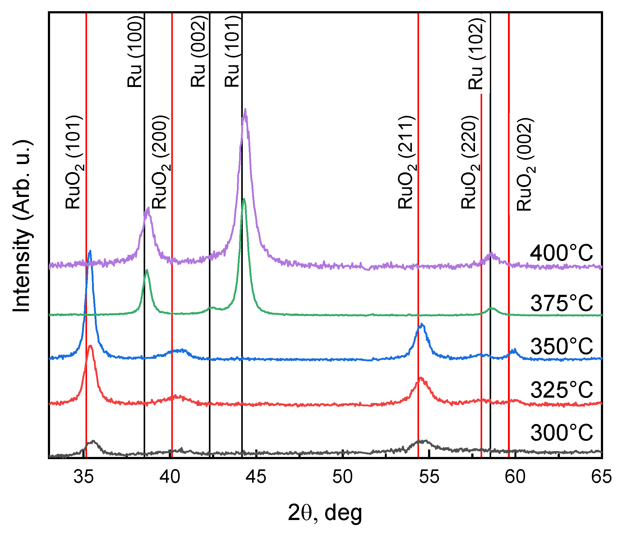
The GXRD spectra obtained for the coatings deposited at the temperatures 300–400 °C and reference peak positions (vertical lines) for Ru [40] and RuO2 [41] in the randomly oriented powders are presented in Figure 2. It can be seen that the spectra of samples 3–5 contain only the peaks that are in line with the randomly oriented tetragonal RuO2 phase (P42/mnm). On the other hand, the spectra of samples 6 and 7 contain the peaks that coincide only with the randomly oriented hexagonal Ru phase (P63/mmc). It shows that at a deposition temperature of 375 °C, an abrupt change in surface reaction mechanisms takes place, leading to the changing in film composition and structure from polycrystalline RuO2 at low temperatures to pure Ru film at higher temperatures. However, it should be noted that the resistivity of our RuO2 films is significantly larger than the values reported earlier [42]. The possible reason is the noticeable carbon contamination of ruthenium oxide. All the peaks of RuO2 are displaced to higher angles. This can be explained by the compressive stress in the coatings. The mechanical stress analysis will be presented in the next section.

3.2. Mechanical Stress

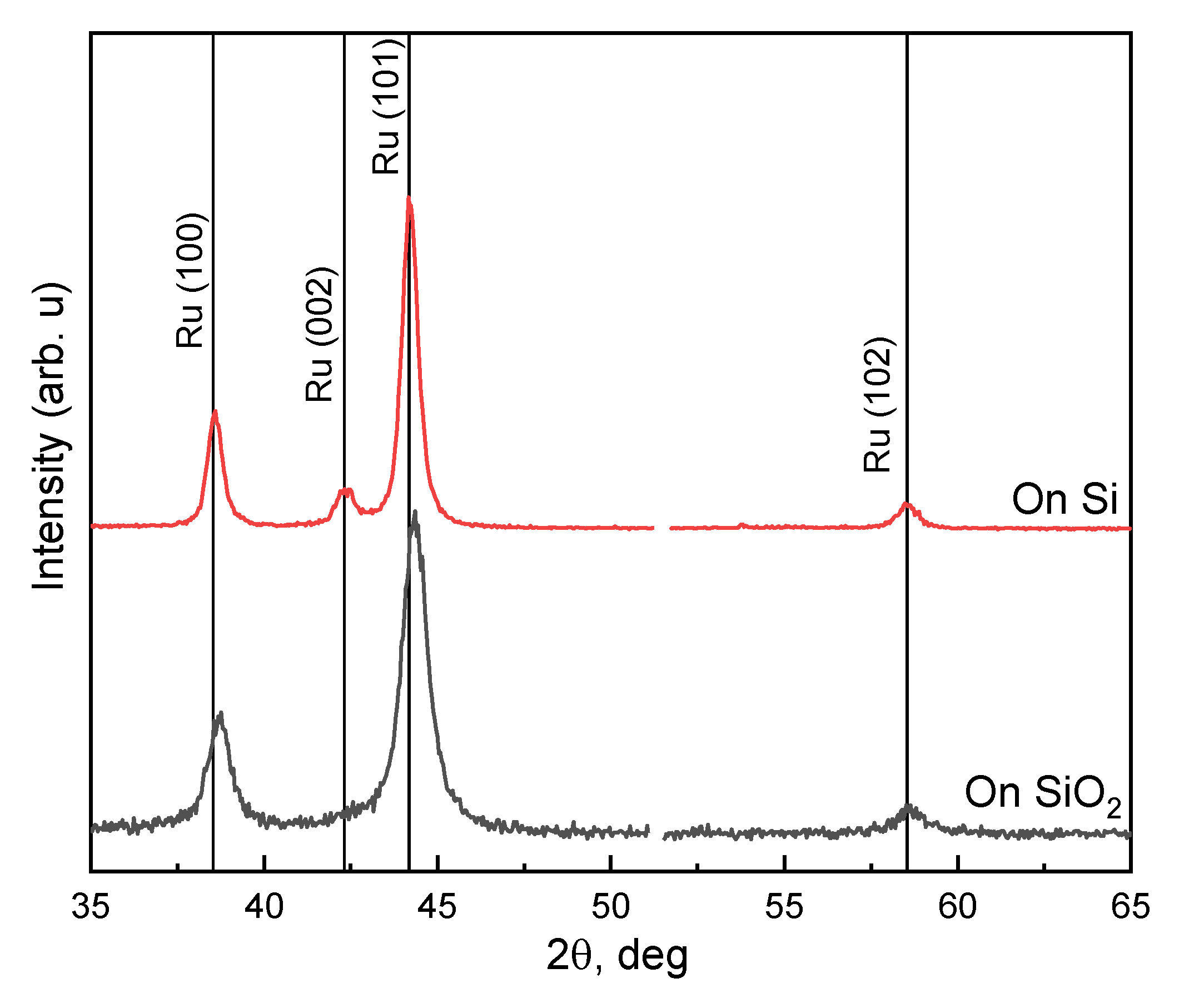
Comparison of the X-ray diffraction curves (Figure 3) on films deposited on Si-wafer and on SiO2(850 nm)/Si-wafer shows a different state of the crystal lattice deformation in the films. The shift of the peaks relative to the reference values shows that Ru film on silicon is in a stressed state. On a sample with an SiO2 film as a surface for Ru deposition, ruthenium film is relaxed with a layer of silicon oxide. The shift in the position of the peaks makes it possible to estimate the Ru lattice deformation on SiO2 of about 0.0039. These data are confirmed by observing the deflection of the substrates under the action of stress in the film. Profilometry of deflection for all films gives stress values of 2.8–4.6 GPa (on Si).
The mechanism of relaxation of the ruthenium film on a single-crystal silicon surface is associated with the formation of blisters. We have observed such ruthenium films blistering on Si-substrate (Figure 4a). It allows us to conclude that the compression stress in these films relaxes significantly, and since no blister of Ru-film is formed on the silicon oxide layer (Figure 4b), the films Ru/SiO2/Si-substrate remains stressed with compression. It is consistent with GXRD data (Figure 3) where Ru-peaks from the films on Si has a smaller shift than ones on SiO2/Si. This different behaviour can be attributed to the different adhesion of films on Si and SiO2 surfaces.
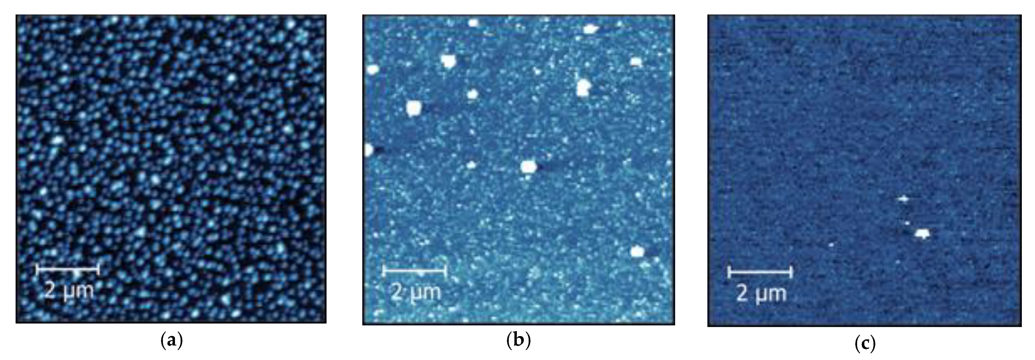
Mechanical stress data are also consistent with the roughness of the films. According to the AFM data, the samples with silicon substrates have a very high surface roughness (RMS = 17.1 nm), due to the formation of blisters (Figure 5a). On samples where there is an upper layer of silicon oxide, the blistering is much less (Figure 5b,c). As was found, the optimal substrate temperature in the ALD process for minimizing the blister formation is 375 °C. In this case, the absence of blistering manifests itself in the minimum surface roughness (RMS = 1.48 nm). It should be noted that blistering also decreases with decreasing film thickness and does not occur at any thickness lower than 10 nm.

3.3. Post Annealing of Films

The deposition of 33 nm thick Ru film by PEALD at 400 °C takes about 3 h. The thermal budget of some applications (for example, interconnects of ICs) is not high enough for such a process. It looks attractive to deposit the film at a lower temperature and then modify it by post-annealing. Samples 3–5 were annealed at 400 °C for 1–2 h. It was found that the thickness of the Ru-based films deposited at low temperature by PEALD reduces substantially during post-annealing (Table 2). This effect was not observed for films produced by PEALD at 375–400 °C.
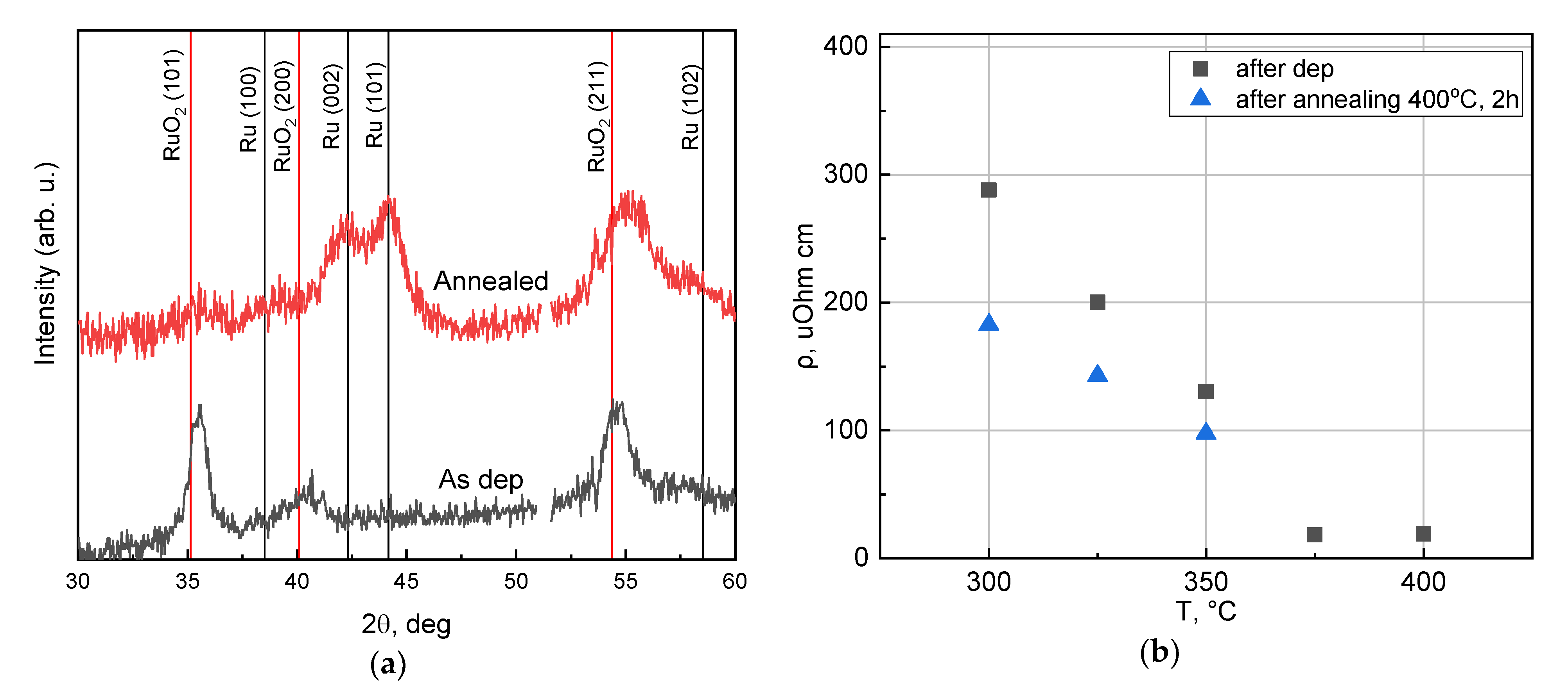
In Figure 6a, GXRD spectra of sample 3 before and after annealing at 400 °C in N2 for 1 h are presented. It can be seen from the graph that during annealing, the composition and the structure of the coating remarkably changed. Polycrystalline tetragonal RuO2 structure changed to a polycrystalline hexagonal Ru film. It appears that during annealing, RuO2 decomposes. The disproportionation reaction with the formation of volatile RuO4 also appears to be possible.
This phase transition was accompanied by electrical resistivity reduction. In Figure 6b, the samples’ resistivity before and after annealing at 400 °C in N2 for 2 h is presented. Nevertheless, in all the cases, the films’ resistivity after annealing remains higher than one for high-temperature samples 6 and 7. For some low-temperature samples, post-annealing led to a resistivity decrease up to 50–60 µOhm·cm. These values are close to the values reported for RuO2 earlier [42].

4. Conclusions

It is possible to deposit ruthenium using both thermal and plasma-enhanced ALD, but almost all authors noted that using PEALD with oxygen plasma leads to lower GPC or absence of the growth at all [18]. This can be explained by oxygen plasma competitive etching of ruthenium in the ALD process producing volatile RuO4 oxide. On the other hand, using PEALD with NH3 plasma, where such mechanism of etching is excluded, amazingly smooth ruthenium films were formed [33].
In a remote plasma ALD system, we have fabricated Ruthenium thin films by PEALD technology using Ru(EtCp)2 and oxygen plasma on silicon and SiO2 surfaces modified by TaN 0.3 nm sub-layer. High uniformity and integrity of films as well as reasonable GPC rate were achieved over the area of 100 mm silicon wafer. Two different ALD regimes of surface reaction between precursors were found in the deposition temperature range of 200–400 °C. At temperatures below 375 °C, polycrystalline ruthenium oxide films were grown. At a higher temperature, pure polycrystalline metal ruthenium coatings were formed.
For 29 nm thick ruthenium coating, it was possible to obtain the surface roughness with RMS = 1.48 nm. It is much lower than films formed by thermal ALD from popular precursors (RMS = 2.6–3.5 nm). To a great extent, the surface roughness of ALD ruthenium films with thickness more than 10 nm can be explained by consequences of mechanical stress in the films.

Author Contributions

Conceptualization, A.R., A.M., and K.R.; PEALD, E.S. and A.M.; XRR and GXRD measurements, A.L.; SIMS measurements and analysis S.S.; AFM measurements, A.R.; optical profilometry, A.M., writing—original draft preparation, A.R. and A.M.; writing—review and editing, A.R., A.M., E.S., and K.R.; supervision, K.R.; project administration, A.R., A.M., and K.R.; funding acquisition, A.R., A.M., and K.R. All authors have read and agreed to the published version of the manuscript.

Funding

The reported study was funded by RFBR according to the research project no. 18-29-27029 and by the Program no. 0066-2019-0004 of the Ministry of Science and Higher Education of Russian Federation for Valiev Institute of Physics and Technology of RAS.

Institutional Review Board Statement

Not applicable.

Informed Consent Statement

Not applicable.

Data Availability Statement

The data presented in this study are available on request from the corresponding author.

Acknowledgments

The authors thank Andrey Tatarintsev for SEM measurements.

Conflicts of Interest

The authors declare no conflict of interest. The funders had no role in the design of the study; in the collection, analyses, or interpretation of data; in the writing of the manuscript, or in the decision to publish the results.

References

  1. Dutta, S.; Kundu, S.; Gupta, A.; Jamieson, G.; Granados, J.F.G.; Bömmels, J.; Wilson, C.J.; Tőkei, Z.; Adelmann, C. Highly Scaled Ruthenium Interconnects. IEEE Electron. Device Lett. 2017, 38, 949–951. [Google Scholar] [CrossRef]
  2. Van der Veen, M.H.; Heyler, N.; Pedreira, O.V.; Ciofi, I.; Decoster, S.; Gonzalez, V.V.; Jourdan, N.; Struyf, H.; Croes, K.; Wilson, C.J.; et al. Damascene Benchmark of Ru, Co and Cu in Scaled Dimensions. In Proceedings of the 2018 IEEE International Interconnect Technology Conference (IITC), Santa Clara, CA, USA, 4–7 June 2018; pp. 172–174. [Google Scholar] [CrossRef]
  3. Croes, K.; Adelmann, C.; Wilson, C.J.; Zahedmanesh, H.; Pedreira, O.V.; Wu, C.; Leśniewska, A.; Oprins, H.; Beyne, S.; Ciofi, I.; et al. Interconnect Metals beyond Copper: Reliability Challenges and Opportunities. In Proceedings of the 2018 IEEE International Electron Devices Meeting (IEDM), San Francisco, CA, USA, 1–5 December 2018; pp. 5.3.1–5.3.4. [Google Scholar] [CrossRef]
  4. Bernasconi, R.; Magagnin, L. Review—Ruthenium as Diffusion Barrier Layer in Electronic Interconnects: Current Literature with a Focus on Electrochemical Deposition Methods. J. Electrochem. Soc. 2018, 166, D3219. [Google Scholar] [CrossRef]
  5. Liang, G.W.; Adelmann, C.; Pedreira, O.V.; Dutta, S.; Popovici, M.; Briggs, B.; Heylen, N.; Vanstreels, K.; Wilson, C.J.; Elshocht, S.V.; et al. Ruthenium Metallization for Advanced Interconnects. In Proceedings of the 2016 IEEE International Interconnect Technology Conference / Advanced Metallization Conference (IITC/AMC), San Jose, CA, USA, 23–26 May 2016; pp. 34–36. [Google Scholar] [CrossRef]
  6. Kwon, O.-K.; Kim, J.-H.; Park, H.-S.; Kang, S.-W. Atomic Layer Deposition of Ruthenium Thin Films for Copper Glue Layer. J. Electrochem. Soc. 2004, 151, 109–112. [Google Scholar] [CrossRef]
  7. Li, Z.; Tian, Y.; Teng, C.; Cao, H. Recent Advances in Barrier Layer of Cu Interconnects. Materials (Basel) 2020, 13, 5049. [Google Scholar] [CrossRef]
  8. Kim, J.-Y.; Kil, D.-S.; Kim, J.-H.; Kwon, S.-H.; Ahn, J.-H.; Roh, J.-S.; Park, S.-K. Ru Films from Bis(Ethylcyclopentadienyl)Ruthenium Using Ozone as a Reactant by Atomic Layer Deposition for Capacitor Electrodes. J. Electrochem. Soc. 2012, 159, 560–564. [Google Scholar] [CrossRef]
  9. Misra, V.; Lucovsky, G.; Parsons, G. Issues in High-K Gate Stack Interfaces. MRS Bull. 2002, 27, 212–216. [Google Scholar] [CrossRef]
  10. Karabanov, S.; Karabanov, A.S.; Suvorov, D.V.; Grappe, B.; Coutier, C.; Sibuet, H.; Sazhin, B.N.; Krutilin, A.A. Nanoscale Ruthenium Coatings of MEMS Switches Contacts. MRS Online Proc. Libr. (OPL) 2010, 1249. [Google Scholar] [CrossRef]
  11. Basu, A.; Hennessy, R.; Adams, G.; McGruer, N. Reliability in Hot Switched Ruthenium on Ruthenium MEMS Contacts. In Proceedings of the 2013 IEEE 59th Holm Conference on Electrical Contacts (Holm 2013), Newport, RI, USA, 22–25 September 2013; pp. 1–8. [Google Scholar] [CrossRef]
  12. Axet, M.R.; Philippot, K. Catalysis with Colloidal Ruthenium Nanoparticles. Chem. Rev. 2020, 120, 1085–1145. [Google Scholar] [CrossRef]
  13. Ordomsky, V.V.; Khodakov, A.Y.; Legras, B.; Lancelot, C. Fischer–Tropsch Synthesis on a Ruthenium Catalyst in Two-Phase Systems: An Excellent Opportunity for the Control of Reaction Rate and Selectivity. Catal. Sci. Technol. 2014, 4, 2896–2899. [Google Scholar] [CrossRef]
  14. Amano, A.; Taylor, H. The Decomposition of Ammonia on Ruthenium, Rhodium and Palladium Catalysts Supported on Alumina. J. Am. Chem. Soc. 1954, 76, 4201–4204. [Google Scholar] [CrossRef]
  15. Hayashi, F.; Toda, Y.; Kanie, Y.; Kitano, M.; Inoue, Y.; Yokoyama, T.; Hara, M.; Hosono, H. Ammonia Decomposition by Ruthenium Nanoparticles Loaded on Inorganic Electride C12A7:E−. Chem. Sci. 2013, 4, 3124–3130. [Google Scholar] [CrossRef]
  16. Sergey, Y. Multilayer Coatings for EUV/Soft X-ray Mirrors. In Optical Interference Coatings; Kaiser, N., Pulker, H.K., Eds.; Springer: Berlin, Germany, 2003; p. 299. [Google Scholar] [CrossRef]
  17. Scholze, F.; Tümmler, J.; Ulm, G. High-Accuracy Radiometry in the EUV Range at the PTB Soft x-Ray Beamline. Metrologia 2003, 40, 224. [Google Scholar] [CrossRef]
  18. Müller, R.; Ghazaryan, L.; Schenk, P.; Wolleb, S.; Beladiya, V.; Otto, F.; Kaiser, N.; Tünnermann, A.; Fritz, T.; Szeghalmi, A. Growth of Atomic Layer Deposited Ruthenium and Its Optical Properties at Short Wavelengths Using Ru(EtCp)2 and Oxygen. Coatings 2018, 8, 413. [Google Scholar] [CrossRef] [Green Version]
  19. Hill, S.B.; Ermanoski, I.; Tarrio, C.; Lucatorto, T.B.; Madey, T.E.; Bajt, S.; Fang, M.; Chandhok, M. Critical Parameters Influencing the EUV-Induced Damage of Ru-Capped Multilayer Mirrors. Proc. SPIE 2007, 6517. [Google Scholar] [CrossRef] [Green Version]
  20. Smith, K.C.; Sun, Y.-M.; Mettlach, N.R.; Hance, R.L.; White, J.M. Evaluation of Precursors for Chemical Vapor Deposition of Ruthenium. Thin Solid Films 2000, 376, 73–81. [Google Scholar] [CrossRef]
  21. Nabatame, T.; Hiratani, M.; Kadoshima, M.; Shimamoto, Y.; Matsui, Y.; Ohji, Y.; Asano, I.; Fujiwara, T.; Suzuki, T. Properties of Ruthenium Films Prepared by Liquid Source Metalorganic Chemical Vapor Deposition Using Ru(EtCp)2 with Tetrahydrofuran Solvent. Jpn. J. Appl. Phys. 2000, 39, L1188. [Google Scholar] [CrossRef]
  22. Sysoev, S.V.; Kuzin, T.M.; Zelenina, L.N.; Zherikova, K.V.; Gelfond, N.V. Thermodynamic Characterization of Ruthenium β-Diketonate Complex Ru(Thd)3 as a Precursor for the CVD Preparation of Coatings. Russ. J. Inorg. Chem. 2020, 65, 747–751. [Google Scholar] [CrossRef]
  23. Senzaki, Y.; Gladfelter, W.L.; McCormick, F.B. Chemical Vapor Deposition of Ruthenium and Osmium Thin Films Using (Hexafluoro-2-Butyne)Tetracarbonylruthenium and –Osmium. Chem. Mater. 1993, 5, 1715–1721. [Google Scholar] [CrossRef]
  24. Papadatos, F.; Consiglio, S.; Skordas, S.; Eisenbraun, E.T.; Kaloyeros, A.E.; Peck, J.; Thompson, D.; Hoover, C. Chemical Vapor Deposition of Ruthenium and Ruthenium Oxide Thin Films for Advanced Complementary Metal-Oxide Semiconductor Gate Electrode Applications. J. Mater. Res. 2004, 19, 2947–2955. [Google Scholar] [CrossRef]
  25. Aaltonen, T.; Alén, P.; Ritala, M.; Leskelä, M. Ruthenium Thin Films Grown by Atomic Layer Deposition. Chem. Vap. Depos 2003, 9, 45–49. [Google Scholar] [CrossRef]
  26. Lee, J.; Song, Y.W.; Lee, K.; Lee, Y.; Jang, H.K. Atomic Layer Deposition of Ru by Using a New Ru-Precursor. ECS Trans. 2006, 2, 1–11. [Google Scholar] [CrossRef]
  27. Kukli, K.; Aarik, J.; Aidla, A.; Jõgi, I.; Arroval, T.; Lu, J.; Sajavaara, T.; Laitinen, M.; Kiisler, A.-A.; Ritala, M. Atomic Layer Deposition of Ru Films from Bis(2,5-Dimethylpyrrolyl)Ruthenium and Oxygen. Thin Solid Films 2012, 520, 2756–2763. [Google Scholar] [CrossRef]
  28. Yeo, S.; Choi, S.-H.; Park, J.-Y.; Kim, S.-H.; Cheon, T.; Lim, B.-Y.; Kim, S. Atomic Layer Deposition of Ruthenium (Ru) Thin Films Using Ethylbenzen-Cyclohexadiene Ru (0) as a Seed Layer for Copper Metallization. Thin Solid Films 2013, 546, 2–8. [Google Scholar] [CrossRef]
  29. Minjauw, M.M.; Dendooven, J.; Capon, B.; Schaekers, M.; Detavernier, C. Atomic Layer Deposition of Ruthenium at 100 °C Using the RuO4-Precursor and H2. J. Mater. Chem. C 2015, 3, 132–137. [Google Scholar] [CrossRef]
  30. Kukli, K.; Kemell, M.; Puukilainen, E.; Aarik, J.; Aidla, A.; Sajavaara, T.; Laitinen, M.; Tallarida, M.; Sundqvist, J.; Ritala, M. Atomic Layer Deposition of Ruthenium Films from (Ethylcyclopentadienyl)(Pyrrolyl)Ruthenium and Oxygen. J. Electrochem. Soc. 2011, 158, 158. [Google Scholar] [CrossRef]
  31. Leick-Marius, N. Atomic Layer Deposition of Ruthenium Films: Properties and Surface Reactions. Ph.D. Thesis, Technische Universiteit Eindhoven, Eindhoven, The Netherlands, 2014. [Google Scholar]
  32. Hämäläinen, J.; Ritala, M.; Leskelä, M. Atomic Layer Deposition of Noble Metals and Their Oxides. Chem. Mater. 2014, 26, 786–801. [Google Scholar] [CrossRef]
  33. Park, S.-J.; Kim, W.-H.; Lee, H.-B.-R.; Maeng, W.J.; Kim, H. Thermal and Plasma Enhanced Atomic Layer Deposition Ruthenium and Electrical Characterization as a Metal Electrode. Microelectron. Eng. 2008, 85, 39–44. [Google Scholar] [CrossRef]
  34. Lu, J.; Elam, J.W. Low Temperature ABC-Type Ru Atomic Layer Deposition through Consecutive Dissociative Chemisorption, Combustion, and Reduction Steps. Chem. Mater. 2015, 27, 4950–4956. [Google Scholar] [CrossRef]
  35. Smirnova, E.A.; Miakonkikh, A.V.; Rogozhin, A.E.; Rudenko, K.V. Atomic Layer Deposition of Ruthenium on Different Interfaces for an Advanced Metallization System of ICs. J. Phys. Conf. Ser. 2020, 1695, 012045. [Google Scholar] [CrossRef]
  36. Yim, S.-S.; Lee, D.-J.; Kim, K.-S.; Kim, S.-H.; Yoon, T.-S.; Kim, K.-B. Nucleation Kinetics of Ru on Silicon Oxide and Silicon Nitride Surfaces Deposited by Atomic Layer Deposition. J. Appl. Phys. 2008, 103, 113509. [Google Scholar] [CrossRef]
  37. Somani, S.; Mukhopadhyay, A.; Musgrave, C. Atomic Layer Deposition of Tantalum Nitride Using A Novel Precursor. J. Phys. Chem. C 2011, 115, 11507–11513. [Google Scholar] [CrossRef]
  38. Rudenko, K.V.; Myakon’kikh, A.V.; Rogozhin, A.E.; Gushchin, O.P.; Gvozdev, V.A. Atomic Layer Deposition in the Production of a Gate HkMG Stack Structure with a Minimum Topological Size of 32 Nm. Russ. Microelectron 2018, 47, 1–10. [Google Scholar] [CrossRef]
  39. Ardigo, M.R.; Ahmed, M.; Besnard, A. Stoney Formula: Investigation of Curvature Measurements by Optical Profilometer. AMR 2014, 996, 361–366. [Google Scholar] [CrossRef] [Green Version]
  40. Morozkin, A.V.; Seropegin, Y.D. Sm–Ru–Ge System at 1070 K. J. Alloys Compd. 2004, 365, 168–172. [Google Scholar] [CrossRef]
  41. Foo, M.L.; Huang, Q.; Lynn, J.W.; Lee, W.L.; Klimczuk, T.; Hagemann, I.S.; Ong, N.P.; Cava, R.J. Synthesis, Structure and Physical Properties of Ru Ferrites: BaMRu5O11 (M=Li and Cu) and BaM′2Ru4O11 (M′=Mn, Fe and Co). J. Solid State Chem. 2006, 179, 563–572. [Google Scholar] [CrossRef]
  42. Austin, D.Z.; Jenkins, M.A.; Allman, D.; Hose, S.; Price, D.; Dezelah, C.L.; Conley, J.F. Atomic Layer Deposition of Ruthenium and Ruthenium Oxide Using a Zero-Oxidation State Precursor. Chem. Mater. 2017, 29, 1107–1115. [Google Scholar] [CrossRef]
Figure 1. (a) Resistivity vs. deposition temperature; (bd) secondary ion mass spectrometry (SIMS) yield of 18O, 102Ru, and carbon-containing ions in the coatings deposited at different temperatures, respectively.
Coatings 11 00117 g001
Figure 2. Grazing incidence XRD (GXRD) spectra obtained for the coatings deposited at temperatures 300–400 °C.
Coatings 11 00117 g002
Figure 3. GXRD pattern of as grown Ru deposited at substrate temperature 400 °C on Silicon and SiO2(850 nm)/Si substrates.
Coatings 11 00117 g003
Figure 4. SEM image of ruthenium film on Silicon (a) and SiO2(850 nm)/Si (b) substrates.
Coatings 11 00117 g004
Figure 5. Atomic force microscopy (AFM) images of the surface of (a) ruthenium film deposited at 400 °C on silicon (vertical scale—90 nm, surface roughness RMS = 17.1 nm); (b) ruthenium film deposited at 400 °C on SiO2 (vertical scale—12 nm, blisters are out of scale, surface roughness RMS = 5.05 nm); (c) ruthenium film deposited at 375 °C on SiO2 (vertical scale—8 nm, blisters are out of scale, surface roughness RMS = 1.48 nm).
Coatings 11 00117 g005
Figure 6. (a) GXRD spectra obtained for the film, deposited at 300 °C, before and after additional annealing at 400 °C in N2 for 1 h; (b) resistivity of the samples before and after post-annealing at 400 °C in N2 for 2 h vs. deposition temperature.
Coatings 11 00117 g006
Table 1. Parameters of the samples.
Sample ## of TaN Cycles# of Ru CyclesDep Temp, °CThickness, nmResistivity, µOhm·cm
157502006 ± 1 *652.6 ± 1.5
257502509 ± 1 *508.5 ± 1.5
3575030017 ± 2288.0 ± 1.0
4575032520 ± 2200.2 ± 1.0
5575035025 ± 2130.5 ± 1.0
6575037527 ± 1 **18.2 ± 0.8
7575040033 ± 1 **19.1 ± 0.8
* Measured by spectroscopic ellipsometry on Si; ** Measured by scanning electron microscopy (SEM) and X-ray reflectometry (XRR).
Table 2. Thicknesses of the films immediately after deposition and after annealing at 400 °C in N2 for 2 h.
# of SampleThickness after Deposition, nmThickness after Annealing, nm
317 ± 29 ± 2
420 ± 210.7 ± 2
525 ± 214.7 ± 2
Publisher’s Note: MDPI stays neutral with regard to jurisdictional claims in published maps and institutional affiliations.