Article

Durable Soft Mold for Imprinting of High-Adhesive Resin

1
School of Mechanical Engineering, Kyungpook National University, Daegu 41566, Korea
2
Electrical Electronics and Computer Science, University of Michigan, Ann Arbor, MI 48105, USA
*
Author to whom correspondence should be addressed.
Coatings 2021, 11(2), 137; https://doi.org/10.3390/coatings11020137
Submission received: 17 December 2020 / Revised: 16 January 2021 / Accepted: 21 January 2021 / Published: 27 January 2021

Abstract

:
A variety of polymer resins have been used to fabricate micro/nano structures via imprint lithography. In addition, with an interest in productivity, there is an increasing demand for the study of the process of easily demolding a cured resin from a mold for continuous fabrication of micro/nanostructures applying imprint lithography to the roll-type equipment. Among these polymer resins, Norland optical adhesive (NOA) in particular is widely used to fabricate micro/nano structure-based functional surfaces because of its shape memory characteristics, biocompatibility, and great optical characteristics. However, the cured NOA is originally used as an epoxy-based adhesive with its high adhesion. NOA has many advantages as a UV-curable adhesive, but as a resin in the imprint process, such adhesion brings a limitation. This high adhesion of cured NOA causes defects in the mold during the demolding process, so it is difficult to apply it to the continuous fabrication process. Here, we present a durable polyurethane acrylate (PUA) soft mold capable of clean demolding of an epoxy-based polymer resin having high adhesion by depositing metal on a surface. Au and Ni were deposited to a thickness of 100 Å by using an E-beam evaporator. To verify the surface characteristics, each metal-deposited soft mold was compared with the previously used soft mold by measuring the contact angle and calculating surface energy. To test a performance of our soft mold, we imprinted nanoline pattern with NOA as a resin using metal-deposited soft mold in roll to roll (R2R) process for more than 240 replications for 90 min of operation time. It is expected that this study can be used for mass production of pattern with epoxy-based patterns required in many fields.

1. Introduction

For general replication of micro/nano structures using the imprint process, the acrylate-based polyurethane acrylate (PUA) has been used frequently as a photo-curable polymer resin because it is transparent and flexible [1]. Therefore, PUA is often used in the roll to roll (R2R) imprint process owing to its special properties for the UV imprint lithography process. Recently, various polymer resins with specific properties are used to fabricate micro/nano structures. Among these polymers, the epoxy-based Norland optical adhesive (NOA), known as an ultraviolet (UV) curable adhesive due to its strong adhesive characteristic is studied in bioscience. Microfluidic chips are fabricated with NOA [2,3] and NOA is being used for cell culturing and characterization [4,5,6] and selective cultivation of microorganisms [7] because of its non-toxic property for bio. Furthermore, the shape memory characteristics of NOA are being studied [6,8,9,10].
Like PUA and polydimethylsiloxane (PDMS), NOA polymers are generally imprinted using PUA soft molds and PDMS soft molds [4,5,7,11]. However, when NOA polymer is used in the imprinting process with PUA soft molds that are not surface-treated, it often causes damage to the PUA soft molds as shown in Figure 1. Figure 1a shows that the PUA pattern is detached from the PUA soft mold. Furthermore, the PUA soft mold is peeled off from the imprint roll in the R2R imprinter as shown in Figure 2b. These soft mold defects are caused by the high adhesion of NOA mentioned above. The structure of a soft mold fabricated with PDMS can be collapsed by high pressure, the resolution of nanostructure replication is not high, and it is difficult to attach to an imprint roll. Therefore, the epoxy-based NOA polymer resin is difficult to apply to the R2R imprint process due to its high adhesion after curing and defects of soft molds.
In previous studies, to reduce the surface energy of soft molds, various surface treatment methods have been studied. PDMS layer coating to soft molds [12] is one of the surface treatments good for NOA imprinting, but it has a disadvantage in that it makes it difficult to control the coating thickness of PDMS. Furthermore, there are other surface treatments where the surface of soft molds are coated using a fluoropolymer [11,13,14], or passivated with a fluorinated silane [15,16]. In the fluorinated silane coating, the strong bonding between a substrate and a coating layer is due to the covalent bond between silane groups of the oxidized substrate and the coating materials. However, fluorinated silane is very sensitive to water and it can lead to non-uniform coating and surface roughening of the fluorinated silane layer because of the copolymerization of the fluorinated silane [12]. In general, there are problems in that the surface performance treated fluorinated silane deteriorates after consecutive uses in short time. We confirmed surface performance of each surface treatment using NOA in R2R imprinting process. The fluorinated silane method is a relatively simple process condition, but the soft mold was detached from the imprint roll before five replications in the R2R continuous fabrication process. In the passivation process, the soft mold was detached before ten replications. In the case of the PDMS layer coating, it was difficult to control the PDMS coating thickness in the fabrication process, and the surface was not clean due to the process of washing out the unreacted PDMS.
To improve the above disadvantages, we present a semi-permanent PUA soft mold capable of clean demolding of an epoxy-based polymer resin having high adhesion by depositing metal on a surface. We checked that fabricated metal-deposited PUA soft mold has similar surface compared to PDMS mold by measuring contact angles. Furthermore, it was demonstrated that the fabricated metal-deposited PUA soft mold can be imprinted several times in R2R imprint process using NOA resin for a long time without defects on the PUA soft mold even with single metal deposition.

2. Materials and Methods

2.1. Fabrication of PUA Soft Mold

Soft molds were fabricated with PUA which has a fast curing speed and excellent properties, allows self-replication, and can easily shape and transfer patterns of several nanometers. For easy attachment of a soft mold to an imprint roll, sticker type polyethylene terephthalate (PET) film with one side coated with urethane and the other side treated with an adhesive was used. After applying an appropriate amount of the photo-curable polymer PUA to a 6-inch silicon master mold, it was covered with the sticker type PET film. PUA between PET film and the master mold was squeezed by applying appropriate pressure with a rubber roller. As the UV dose of PUA is 150 mJ/cm2, the pressurized polymer resin was placed in a UV curing device at the intensity of 10 mW/cm2 and cured by irradiating UV light for 15–20 s. The cured soft mold was released from the master mold. For durability and self-replication of fabricated nanostructures, over-curing process to remove the residual solvent inside PUA was performed for at least 8 h in a UV curing equipment.

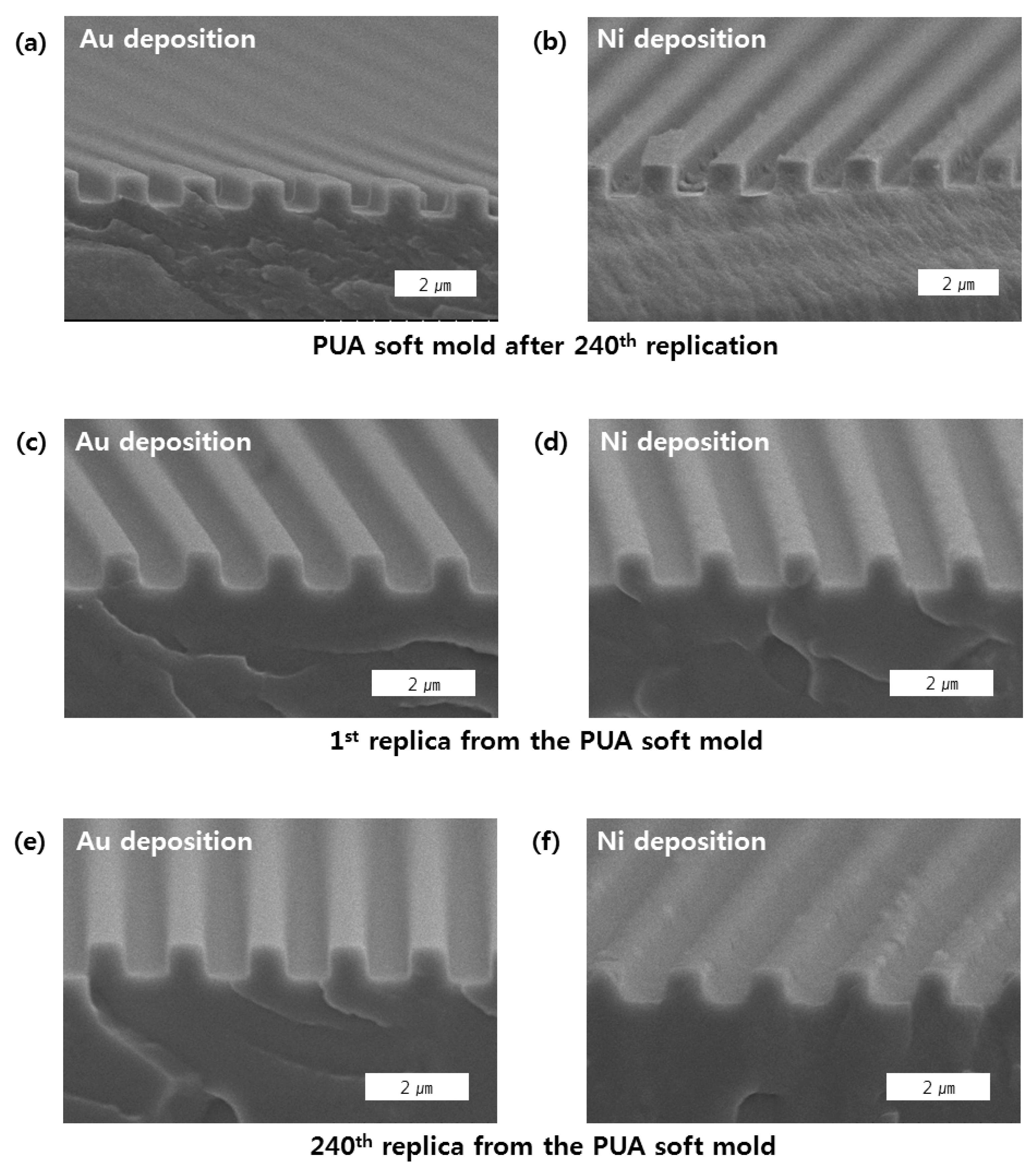
2.2. Metal Deposition on PUA Soft Mold

For surface treatment to enhance the durability of the soft mold made of the photo-curable polymer resin PUA, the metals Au and Ni were deposited at 100 Å using an e-beam evaporator from SORONA (Anseong, Korea). Au and Ni were deposited with pressure of 2 Pa, temperature of 25 °C, voltage of 9.9 kV, and current of 88 mA for 150 s. Figure 2a shows a scanning electron microscope (SEM) image of the cross-section of the PUA soft mold without surface treatment. Figure 2b,c show the images of the Au and Ni depositions at 100 Å. These images using SEM from Hitachi High-Technologies (Tokyo, Japan) confirm that the surface structure of the metal-deposited soft mold has no problem.

2.3. Self-Assembled Monolayer (SAM) Treatment on PUA Soft Mold

For the fabricated soft molds, the vapor deposition of perfluorinated silane was performed to lower the surface energy. Before vapor deposition, the surfaces of the soft molds were modified for 45 s under a pressure of 244 Pa at 150 W and 50 kHz in a plasma processor from FEMTO SCIENCE (Hwaseong, Korea). The surface-modified soft mold was sealed and vapor-deposited for 3 min at 70 °C after one drop of perfluorinated silane was dropped on a petri dish.

2.4. Attaching PUA Soft Mold on Imprint Roll

The window tinting method of vehicles was used to prevent air bubbles, which can be easily generated when attaching the sticker type PUA soft mold on the imprint roll. The adhesive surface of the PUA soft mold was soaked in soap water. The soap water was squeezed by rolling the imprint roll and the PUA soft mold was attached on the imprint roll without air bubbles during the rolling process simultaneously. Finally, the liquid soap water was evaporated for 24 h at room temperature or for 1 h in an oven at 70 °C to complete the attachment process.

2.5. Contact Angle Measurement

The contact angles on the surfaces of the PDMS mold, Au- and Ni-deposited molds, and PUA mold were measured using 5 µL of deionized (DI) water with a contact angle measuring instrument from FEMTOBIOMED (Seongnam, Korea). For the nanoline pattern, θ and θ were the contact angles measured parallel and perpendicular to the nanoline by dropping DI water, respectively.

3. Results and Discussion

For the NOA series of epoxy-based polymer resin, micro/nanostructures were imprinted using PDMS soft molds with a low surface energy due to high viscosity before curing and adhesiveness after curing. However, PDMS could not be used for continuous fabrication due to deformation at high pressures, difficulty of adjusting the thickness of soft molds, and the difficulty of attachment to the imprint roll [17]. In the present study, firm and flexible soft molds whose micro/nanostructures do not collapse even under high pressure were fabricated by depositing metals on PUA-based patterns. In addition, the surface changes of the fabricated metal-deposited soft mold were measured and compared, and the surface energy was calculated by obtaining the calibrated contact angle.
The pattern used in the soft mold was a line pattern with a width of 771 mm, a period of 848 nm, and a height of 603 nm. When a liquid is dropped to measure the contact angle, the liquid spreads along the line pattern. Thus, both the contact angles of parallel ( θ ) and perpendicular ( θ ) to nanoline were measured. The surface changes of the metal-deposited soft mold can be verified by the measured contact angle, and the surface energy can be compared simply with other soft molds through the Girifalco–Good–Fowkes–Young model. This model is a relatively simple equation for measuring the contact angle and obtaining the surface energy of the soft mold using one measuring liquid. It can be derived as follows.
The energy between two surfaces can be simply expressed using the Berthelot geometric mean equation as follows [18,19]:
γ S L = ( γ S V γ L V ) 2
Furthermore, Young’s equation can be expressed by the Fowkes equation [20] as follows:
cos   θ =   γ S V γ S L γ L V
When the above two equations are combined to predict the surface energy of the soft mold, we obtain the following Girifalco–Good–Fowkes–Young equation [18]:
γ S V =   γ L V ( 1 + cos   θ ) 2 4
where γ S L denotes the interfacial energy between the soft mold and the measuring liquid, γ L V denotes the surface energy of the measuring liquid, and γ S V denotes the surface energy of the soft mold. In this study, the γ L V value is fixed at 72.8 mJ/m2 because DI water was used for measuring the contact angle. From Equation (3), the surface energy of the soft mold decreases as the contact angle of the liquid increases, and vice versa. Accordingly, the magnitude of surface energy can be simply compared by measuring θ and θ of each soft mold.
The measured angles are shown in Figure 3. Furthermore, there is a difference in the contact angles for an anisotropic surface of each soft mold. Figure 3a shows contact angles of the PDMS soft mold, which has been traditionally used for patterning epoxy-based NOA series polymer resin.   θ and θ of PDMS soft mold were measured at 129.9° and 115.2°, respectively. As the patterning durability of PDMS soft mold has been proven in previous studies, the measured contact angles were used as the reference values for comparing the performances of other soft molds. Figure 3b shows the over-cured PUA soft mold, which is often used when fabricating micro/nanostructures, for which θ and θ were measured at 97.4° and 60.5°, respectively. When compared with the PDMS soft mold, it has a relatively high surface energy and it can be predicted that a problem can be caused in the imprinting process using NOA resin. Figure 3c,d show the surface contact angles of the soft molds fabricated by depositing the metals Au and Ni at 100 Å. θ and θ of the Au-deposited PUA soft mold were measured at 148.5° and 113.2°, respectively, and those of the Ni-deposited mold were measured at 142.8° and 67°, respectively. Thus, when metal-deposited PUA soft mold was compared with the PUA soft mold with no deposition, the measured θ and θ were higher than them, respectively which proves that the surface of the metal-deposited soft mold was modified. The degree of wetting anisotropy can be defined as θ Δ ( θ θ ) [21]. θ Δ of Ni-deposited PUA soft mold was measured at 75.8°; it is much bigger than θ Δ of Au-deposited PUA soft mold (35.3°). This result indicates a difference of effect for Au and Ni deposition. Tanaka et al. reported that the surface treatment of a 1D structure directly influences the wettability parallel to the nanoline, although the wettability perpendicular to the nanoline is influenced by the formation of a free-energy barrier. Because the free-energy barrier formation slightly depends on the surface treatment, the surface treatment influences θ more directly that it influences θ [21]. Thus, θ of Ni-deposited mold is much bigger than θ of Au-deposited mold; this suggests that the Ni-deposited surface has stronger energy and wettability than the Au-deposited surface.
From the movement of liquid along the nanoline pattern in Figure 3, the contact angles can be considered to have been measured in Wenzel state [22,23,24,25,26,27]. To derive the accurate surface energy of the soft molds, a process of calibrating the contact angle measured in Wenzel state to a contact angle on a flat surface is required. This can be achieved by the following equation:
cos   θ w = r   cos   θ
where θ w denotes the contact angle in Wenzel state and r denotes the roughness factor of a structure. The roughness factor r is defined as the ratio of actual surface area to that of a projected area [28,29,30]. Here, from the literature, the equation for calculating the roughness factor of a nanoline pattern is as follows [27,31]:
r = 1 +   2 h ( l + a ) l ( a + b )
here h denotes the height of the nanoline, l denotes the length of the nanoline, a denotes the width of the nanoline, and b denotes the spacing of nanolines. Usually, nanoline pattern is composed of much larger l compared to other factors (a, b, h). Thus, the a factor in numerator of Equation (5) is a neglectable value and (l + a) in numerator can be considered as just l. Therefore, Equation (5) can be simplified further as Equation (6) and the roughness factor of the nanoline pattern can be calculated more easily.
r   1 +   2 ( h / a ) ( 1 + b / a )
The values of h, a, and b were measured at 603 nm, 771 nm, and 848 nm, respectively. When these values are substituted in Equation (6), the r value is calculated as 1.745. The calibrated contact angles can be determined by substituting the r value and the contact angles of the soft molds in Wenzel state in Figure 3. Table 1 outlines the surface energies calculated by substituting the contact angles of each soft mold in Wenzel state and the calibrated contact angles in Equation (3). As observed from the above contact angle measurement result, the PUA soft mold with no deposition had the highest surface energy. Among the soft molds fabricated by metal deposition, the Au-deposited PUA soft mold had the lowest surface energy at 4.8 mJ/m2, and the surface energy of the Ni-deposited soft mold was measured at 5.4 mJ/m2. These surface energies were lower than the surface energy of the untreated PDMS soft mold (7.3 mJ/m2), which is the reference mold for patterning polymer resins with high viscosity and adhesion after curing, such as the epoxy-based NOA series. This verifies that metal-deposited PUA soft molds have a higher performance and can be sufficiently used as a substitute soft mold for the PDMS soft mold.
To evaluate the performance of the metal-deposited PUA soft molds in the R2R imprint continuous fabrication process, we performed continuous replications using the automatic R2R imprint equipment in Figure 4, which we had produced to enable the mass production of micro/nanostructures. The process conditions were set as follows: an imprint speed of 2.5 cm/s, a UV intensity of 1050 mW/cm2, and a tension force of the film of 58.8~68.6 N.
In the PUA soft mold with no metal deposition in the R2R imprint continuous process, the mold was detached from the imprint roll after four replications. This is presumably caused by the high surface energy that is approximately three times higher than those of other soft molds as shown in Table 1. In the case of the soft molds fabricated by depositing Au and Ni metals, the replications were performed cleanly with no detachment of the soft mold from the imprint roll for approximately 240 continuous replications for a process time of 90 min. After the above process, the surfaces of the metal-deposited PUA soft mold and its replicas were observed using SEM. Figure 5a,c,e show the SEM images of the surfaces of the first and 240th replicas as well as after the 240th continuous replications of the Au-deposited PUA soft mold, respectively. The surface of the Au-deposited PUA soft mold after the 240 continuous replications was not considerably different from the surface of the initial soft mold as shown in Figure 5a. It can be observed that the first to 240th replicas were demolded successfully with no structural changes as shown in Figure 5c,e.
Figure 5b,d,f show the surface SEM images of the Ni-deposited PUA soft mold after 240 replications and the first and 240th replicas, respectively. The surface image of the Ni-deposited PUA soft mold after 240 replications shows many contaminations compared with the soft mold before the replication process as shown in Figure 5b. Furthermore, it can be observed that the surface of the first replica is clean (Figure 5d), but the surface of the 240th replica (Figure 5e) is more contaminated. This appears to be caused by the high value of the surface energy of the Ni-deposited PUA soft mold in Table 1, which is higher by 0.6 mJ/m2 than that of the Au-deposited PUA soft mold. As shown by the result of a polyimide polymer resin peeling experiment in metal-deposited films with a thickness of 5000 Å performed by other researchers [32,33], the forces required for peeling polymer resin from the Ni-deposited and Au-deposited films were measured at 86 g/mm and 31 g/mm, respectively. This suggests that it has been experimentally proven that the Ni-deposited surface requires a higher force for peeling the polymer resin than the Au-deposited surface. Accordingly, it is presumed that the durability of the Ni-deposited soft mold decreases due to the higher surface energy than that of the Au-deposited soft mold as the number of replications increases. Hence, it can be predicted that, to perform more than 240 continuous replications, the Au-deposited PUA soft mold is more appropriate than the Ni-deposited PUA soft mold. We demonstrated that Au-deposited PUA soft mold is enough to substitute for the PDMS mold in R2R continuous imprint process using NOA through the comparison of surface energy using contact angle measurement and the performance experiment in the R2R imprint process.

4. Conclusions

We produced metal-deposited PUA soft molds of the sticker type for the continuous fabrication of micro/nanostructures using NOA76, which is a photo-curable adhesive having high viscosity and adhesion after curing. Furthermore, the surface energies were compared by measuring the contact angles of a PDMS soft mold, which is often used for the replication of NOA-series polymer resins, and a PUA soft mold with no metal deposition. The result confirmed that the metal-deposited PUA soft mold can sufficiently replace the PDMS soft mold. In addition, the metal-deposited PUA soft mold was attached to an R2R continuous fabrication equipment, and the SEM images of the replicas produced by continuous replications for 90 min and the PUA soft mold were compared. As the durability of the fabricated Au-deposited soft mold was higher than that of the Ni-deposited soft mold, it was predicted that the Au-deposited soft mold would be more advantageous in the continuous replication process of the epoxy-based polymer resins for a long time. By using metal-deposited PUA soft mold, we expect a mass production of epoxy-based nano/micro patterns required in many fields.

Author Contributions

Conceptualization, M.K.K., J.L., and S.H.L.; methodology, M.K.K., J.L., and S.H.L.; investigation, M.K.K., J.L., and S.H.L.; writing—original draft preparation, M.K.K. and J.L.; writing—review and editing, M.K.K., J.L., and S.H.L.; supervision, M.K.K.; All authors have read and agreed to the published version of the manuscript.

Funding

This work was supported by the Korea Institute of Planning and Evaluation for Technology in Food, Agriculture and Forestry funded by the Ministry of Agriculture, Food and Rural Affairs (119056-2) and the National Research Foundation of Korea grant (NRF-2020R1A4A1018652 and 2019R1A2C1086766), which was funded by the Korean government.

Data Availability Statement

Not applicable.

Conflicts of Interest

The authors declare no conflict of interest.

References

  1. Choi, S.-J.; Kim, H.N.; Bae, W.G.; Suh, K.-Y. Modulus-and surface energy-tunable ultraviolet-curable polyurethane acrylate: Properties and applications. J. Mater. Chem. 2011, 21, 14325–14335. [Google Scholar] [CrossRef]
  2. Ding, H.; Li, X.; Lv, X.; Xu, J.; Sun, X.; Zhang, Z.; Wang, H.; Deng, Y. Fabrication of micro free-flow electrophoresis chip by photocurable monomer binding microfabrication technique for continuous separation of proteins and their numerical simulation. Analyst 2012, 137, 4482–4489. [Google Scholar] [CrossRef] [PubMed]
  3. Dupont, E.P.; Luisier, R.; Gijs, M.A. NOA 63 as a UV-curable material for fabrication of microfluidic channels with native hydrophilicity. Microelectron. Eng. 2010, 87, 1253–1255. [Google Scholar] [CrossRef]
  4. Carson, D.; Hnilova, M.; Yang, X.; Nemeth, C.L.; Tsui, J.H.; Smith, A.S.; Jiao, A.; Regnier, M.; Murry, C.E.; Tamerler, C. Nanotopography-induced structural anisotropy and sarcomere development in human cardiomyocytes derived from induced pluripotent stem cells. ACS Appl. Mater. Interfaces 2016, 8, 21923–21932. [Google Scholar] [CrossRef] [Green Version]
  5. Jeon, H.; Tsui, J.H.; Jang, S.I.; Lee, J.H.; Park, S.; Mun, K.; Boo, Y.C.; Kim, D.-H. Combined effects of substrate topography and stiffness on endothelial cytokine and chemokine secretion. ACS Appl. Mater. Interfaces 2015, 7, 4525–4532. [Google Scholar] [CrossRef] [Green Version]
  6. Davis, K.A.; Burke, K.A.; Mather, P.T.; Henderson, J.H. Dynamic cell behavior on shape memory polymer substrates. Biomaterials 2011, 32, 2285–2293. [Google Scholar] [CrossRef]
  7. Lee, N.Y.; Lim, J.R.; Kim, Y.S. Selective patterning and immobilization of biomolecules within precisely-defined micro-reservoirs. Biosens. Bioelectron. 2006, 21, 2188–2193. [Google Scholar] [CrossRef]
  8. DiOrio, A.M.; Luo, X.; Lee, K.M.; Mather, P.T. A functionally graded shape memory polymer. Soft Matter 2011, 7, 68–74. [Google Scholar] [CrossRef] [Green Version]
  9. Kim, C.-L.; Lee, J.-J.; Oh, Y.-J.; Kim, D.-E. Smart wearable heaters with high durability, flexibility, water-repellent and shape memory characteristics. Compos. Sci. Technol. 2017, 152, 173–180. [Google Scholar] [CrossRef]
  10. Nam, S.; Song, M.; Kim, D.-H.; Cho, B.; Lee, H.M.; Kwon, J.-D.; Park, S.-G.; Nam, K.-S.; Jeong, Y.; Kwon, S.-H. Ultrasmooth, extremely deformable and shape recoverable Ag nanowire embedded transparent electrode. Sci. Rep. 2014, 4, 4788. [Google Scholar] [CrossRef] [Green Version]
  11. Kim, Y.S.; Lee, N.Y.; Lim, J.R.; Lee, M.J.; Park, S. Nanofeature-patterned polymer mold fabrication toward precisely defined nanostructure replication. Chem. Mater. 2005, 17, 5867–5870. [Google Scholar] [CrossRef]
  12. Lee, M.J.; Lee, N.Y.; Lim, J.R.; Kim, J.B.; Kim, M.; Baik, H.K.; Kim, Y.S. Antiadhesion Surface Treatments of Molds for High-Resolution Unconventional Lithography. Adv. Mater. 2006, 18, 3115–3119. [Google Scholar] [CrossRef]
  13. Hirai, Y.; Yoshida, S.; Okamoto, A.; Tanaka, Y.; Endo, M.; Irie, S.; Nakagawa, H.; Sasago, M. Mold surface treatment for imprint lithography. J. Photopolym. Sci. Technol. 2001, 14, 457–462. [Google Scholar] [CrossRef]
  14. Zhang, T.; Kobrin, B.; Wanebo, M.; Nowak, R.; Yi, R.; Chinn, J.; Bender, M.; Fuchs, A.; Otto, M. Vapor Deposited Release Layers for Nanoimprint Lithography; Emerging Lithographic Technologies X; International Society for Optics and Photonics: San Jose, CA, USA, 2006; p. 615117. [Google Scholar]
  15. Resnick, D.; Dauksher, W.; Mancini, D.; Nordquist, K.; Bailey, T.; Johnson, S.; Stacey, N.; Ekerdt, J.G.; Willson, C.G.; Sreenivasan, S. Imprint lithography for integrated circuit fabrication. J. Vac. Sci. Technol. B Microelectron. Nanometer Struct. Process. Meas. Phenom. 2003, 21, 2624–2631. [Google Scholar] [CrossRef] [Green Version]
  16. Jung, G.-Y.; Li, Z.; Wu, W.; Chen, Y.; Olynick, D.L.; Wang, S.-Y.; Tong, W.M.; Williams, R.S. Vapor-phase self-assembled monolayer for improved mold release in nanoimprint lithography. Langmuir 2005, 21, 1158–1161. [Google Scholar] [CrossRef]
  17. Lötters, J.C.; Olthuis, W.; Veltink, P.H.; Bergveld, P. The mechanical properties of the rubber elastic polymer polydimethylsiloxane for sensor applications. J. Micromech. Microeng. 1997, 7, 145. [Google Scholar] [CrossRef]
  18. Good, R.J.; van Oss, C.J. The modern theory of contact angles and the hydrogen bond components of surface energies. In Modern Approaches to Wettability; Springer: Berlin/Heidelberg, Germany, 1992; pp. 1–27. [Google Scholar]
  19. Good, R.J. Surface free energy of solids and liquids: Thermodynamics, molecular forces, and structure. J. Colloid Interface Sci. 1977, 59, 398–419. [Google Scholar] [CrossRef]
  20. Smith, R.; Pitrola, R. Influence of casting substrate on the surface free energy of various polyesters. J. Appl. Polym. Sci. 2002, 83, 997–1008. [Google Scholar] [CrossRef]
  21. Tanaka, D.; Buenger, D.; Hildebrandt, H.; Moeller, M.; Groll, J. Unidirectional control of anisotropic wetting through surface modification of PDMS microstructures. Langmuir 2013, 29, 12331–12336. [Google Scholar] [CrossRef]
  22. Murakami, D.; Jinnai, H.; Takahara, A. Wetting transition from the Cassie–Baxter state to the Wenzel state on textured polymer surfaces. Langmuir 2014, 30, 2061–2067. [Google Scholar] [CrossRef] [PubMed]
  23. Forsberg, P.S.; Priest, C.; Brinkmann, M.; Sedev, R.; Ralston, J. Contact line pinning on microstructured surfaces for liquids in the Wenzel state. Langmuir 2009, 26, 860–865. [Google Scholar] [CrossRef] [PubMed]
  24. Peters, A.; Pirat, C.; Sbragaglia, M.; Borkent, B.; Wessling, M.; Lohse, D.; Lammertink, R.G. Cassie-Baxter to Wenzel state wetting transition: Scaling of the front velocity. Eur. Phys. J. E 2009, 29, 391–397. [Google Scholar] [CrossRef] [PubMed]
  25. Manukyan, G.; Oh, J.; Van Den Ende, D.; Lammertink, R.G.; Mugele, F. Electrical switching of wetting states on superhydrophobic surfaces: A route towards reversible Cassie-to-Wenzel transitions. Phys. Rev. Lett. 2011, 106, 014501. [Google Scholar] [CrossRef] [PubMed] [Green Version]
  26. Forsberg, P.; Nikolajeff, F.; Karlsson, M. Cassie–Wenzel and Wenzel–Cassie transitions on immersed superhydrophobic surfaces under hydrostatic pressure. Soft Matter 2011, 7, 104–109. [Google Scholar] [CrossRef]
  27. Jeong, H.E.; Lee, S.H.; Kim, J.K.; Suh, K.Y. Nanoengineered multiscale hierarchical structures with tailored wetting properties. Langmuir 2006, 22, 1640–1645. [Google Scholar] [CrossRef]
  28. Wenzel, R.N. Resistance of solid surfaces to wetting by water. Ind. Eng. Chem. 1936, 28, 988–994. [Google Scholar] [CrossRef]
  29. Rudawska, A. Assessment of surface preparation for the bonding/adhesive technology. In Surface Treatment in Bonding Technology; Elsevier: Amsterdam, The Netherlands, 2019; pp. 227–275. [Google Scholar]
  30. Advincula, R.C. Conducting polymers with superhydrophobic effects as anticorrosion coating. In Intelligent Coatings for Corrosion Control; Elsevier: Amsterdam, The Netherlands, 2015; pp. 409–430. [Google Scholar]
  31. He, B.; Patankar, N.A.; Lee, J. Multiple equilibrium droplet shapes and design criterion for rough hydrophobic surfaces. Langmuir 2003, 19, 4999–5003. [Google Scholar] [CrossRef]
  32. Lee, L.-H. Fundamentals of Adhesion; Springer Science & Business Media: Berlin/Heidelberg, Germany, 2013. [Google Scholar]
  33. Kim, Y.-H.; Kim, J.; Walker, G.; Feger, C.; Kowalczyk, S. Adhesion and interface investigation of polyimide on metals. J. Adhes. Sci. Technol. 1988, 2, 95–105. [Google Scholar] [CrossRef]
Figure 1. Optical images of the defects due to the high adhesion of the cured NOA76 in demolding process using polyurethane acrylate (PUA) soft mold without surface treatment. (a) The PUA pattern detached from the PUA soft mold; (b) The PUA soft mold peeled off from imprint roll in roll to roll (R2R) imprinter.
Coatings 11 00137 g001
Figure 2. Scanning electron microscope (SEM) image of the surface of PUA soft molds. (a) No deposition. (b) Au deposition (100 Å). (c) Ni deposition (100 Å).
Coatings 11 00137 g002
Figure 3. Contact angles of parallel ( θ ) and perpendicular ( θ ) to the nanoline for various soft molds.
Coatings 11 00137 g003
Figure 4. Optical image of the automatic R2R imprint equipment.
Coatings 11 00137 g004
Figure 5. SEM images of metal deposition PUA soft mold and its replica after imprinting process. (a,b) PUA soft mold after 240th replication. (c,d) 1st replica. (e,f) 240th replica. (Left: Au deposition, Right: Ni deposition).
Coatings 11 00137 g005
Table 1. Calibrated contact angle of DI water and surface energy on various soft molds.
Type of Soft Mold Wenzel State
Contact Angle (°)
Calibrated
Contact Angle (°)
Surface Energy
(mJ/m2)
PDMS soft mold129.9 ± 4.0111.67.3
PUA soft mold
(No deposition)
97.4 ± 7.894.215.6
PUA soft mold
(Au deposition)
148.5 ± 3.2119.24.8
PUA soft mold
(Ni deposition)
142.8 ± 2.8117.25.4
Publisher’s Note: MDPI stays neutral with regard to jurisdictional claims in published maps and institutional affiliations.

