Abstract
We evaluated the adhesion of polycrystalline metallic coatings using the laser shock-wave adhesion test (LaSAT). This study used Cu plating on stainless steel as a coating model. The adhesion strength and toughness were successfully estimated using LaSAT and finite element method with cohesive zone model. Next, repeated LaSAT was conducted to apply cyclic loading to evaluate adhesion fatigue life, i.e., the number of loading cycles required for delamination. Furthermore, this study performed molecular dynamics (MD) simulations to elucidate the adhesion mechanism for the Cu/Fe interface. To verify our model, the interfacial fracture toughness was computed using the MD simulation and compared with the results of LaSAT. Next, cyclic loading was applied to the MD model to investigate crack initiation around the interface. We found that dislocations are generated from the internal grain and are accumulated at grain boundaries. This accumulation results in fatigue crack initiation due to stress concentration.
1. Introduction
Metallic and conductive coatings are widely used in electronic devices to improve the electrical properties of materials. One common coating is copper (Cu) plating, a metal with high electrical conductivity that is widely used in industry as a surface mount device for electronic substrates [1,2,3,4,5]. However, during usage, the coating may become delaminated because of difference in the coefficients of thermal expansion between the substrate and the coating and when subjected to repeated loading. Therefore, it is important to evaluate the adhesion strength of the coating, especially the adhesion durability when it is subjected to cyclic loading. Previously, various tests such as the uniaxial tensile test [6,7,8] and the four-point bending test [9,10] have been used to investigate adhesion strength and durability. In uniaxial tensile testing, cylindrical specimens are adhered together with an adhesive and subjected to uniaxial loading. Although uniaxial tensile testing is the simplest method, delamination is likely to occur from the interfacial edge, and the stress singularity field at the edge becomes a serious problem for evaluating the adhesive. This can result in large scattering during quantitative evaluation. Therefore, evaluating the adhesion durability by fatigue delamination using cyclic tensile testing is generally difficult. The four-point bending test is a more convenient method for evaluating adhesion durability than the uniaxial tensile test. However, the testing results are generally highly dependent on the pre-crack introduced to the specimen. In addition, stress concentration at the interfacial edge can still occur, and the contact conditions of the pins under four-point bending may cause scattering in the testing results. To solve these problems, a non-contact testing method using pulsed laser-induced shock waves may be favorable [11]. This technique, called the laser shock adhesion test (LaSAT), was initially developed by Vossen [12] and then improved by Gupta [13]. Strong shock waves produced by laser ablation are used to cause interfacial fracture (delamination) and can be used to evaluate the adhesion strength of films and coatings. This technique enables the local evaluation of the film and coating adhesion because the laser is irradiated on a spot area (the laser diameter is 2–3 mm). Because of the many advantages of this method, LaSAT has been developed by various groups to improve the evaluation of adhesives in films, coatings, and composite materials [14,15,16,17]. Recently, our group improved LaSAT to enable high-cycle laser irradiation and interfacial fatigue testing [18]. This technique has potential for evaluating the adhesion durability of coatings against cyclic loading.
As mentioned above, it is important to evaluate interfacial fatigue for electrical devices, but this can be difficult. Some experiments have been conducted to characterize interfacial fatigue. Most of these studies focused on interfacial fatigue crack growth [10,19], but the evaluation of interfacial fatigue strength (for crack initiation) is still rare. However, we previously used our LaSAT method to successfully evaluate the interfacial fatigue strength of the Cu coating on stainless steel [18], which indicates a clear tendency for fatigue. We could then evaluate the interfacial fatigue life quantitatively. During the initiation of fatigue cracking in metallic or interfacial materials, the fatigue crack initiates from the intrusion and extrusion of slip bands at the free surface and the interface edge. Thus, interfacial fatigue initiation requires interfacial free edges. However, LaSAT is a local adhesion experiment with no interfacial free edges. Indeed, our recent LaSAT study reported that Cu plating showed a fatigue tendency, even though the interfacial specimen could be considered infinite and there was no interfacial edge [18]. Therefore, the mechanism for the fatigue tendency in LaSAT experiments is unknown, and this may be necessary for the evaluation of adhesives and the material design of films or coatings. This insight will increase the reliability of LaSAT experiments and their future improvements.
Experimentally, it is difficult to observe fatigue crack initiation (especially interfacial crack) because it occurs in a very small region (smaller than a grain or on the scale of several nanometers). Molecular dynamics (MD) is a useful method for simulating the deformation process at the atomistic scale, allowing us to investigate the mechanism for fatigue fracture even for interfacial materials. For example, the interfacial fracture of a Cu/Ti/SiO2/Si structure was investigated by Lin et al. [20] in order to model a plated film on an integrated circuit. The interaction forces calculated from the MD simulations were used for finite element method (FEM) computations, so that they compared it with interfacial fracture property obtained from micro-indentation tests. Yashiro et al. [21] also performed an MD simulation of Ni plating on aluminum alloys and discussed the interfacial fracture behavior of Ni coating and the effect of phosphorus on the fracture strength. In a study of fatigue loading using MD, Lei Ma et al. [22] investigated the fatigue crack growth characteristics of pre-cracked single-crystal bcc iron under repeated loading with strain control. In addition, Wu et al. [23] performed a strain-controlled cyclic loading test on single-crystal Ni and discussed the slip zone and stress field at the crack tip. As mentioned above, many MD simulations have been performed to evaluate the adhesion strength of interfacial materials, as well as the fatigue behavior of metallic materials. However, few comprehensive studies have investigated fatigue failure at the coating interface using MD and experiments. As mentioned above, the mechanism of interfacial fatigue failure due to repeated LaSAT is still unknown; however, MD simulations may elucidate this process.
In this study, we conducted repeated LaSAT to evaluate the interfacial fatigue failure (adhesion durability), and we investigated the mechanism of crack initiation using MD simulation. We also summarize our previous results for repeated LaSAT on Cu plating to determine the adhesion durability [18]. For our interfacial model, we used a specimen containing Cu plating on steel. To verify our MD simulation, we first conducted an interfacial crack growth test using an LaSAT experiment to evaluate the interfacial fracture toughness. Next, we conducted an MD simulation to investigate the interfacial crack growth and to evaluate the interfacial fracture toughness. We compared these findings with the experimental result of LaSAT. Finally, we performed MD simulations for cyclic loading on a Cu/Fe interfacial polycrystalline model to elucidate interfacial fatigue failure. This may be useful to increase the reliability of our method of repeated LaSAT and will provide useful material design from the atomistic scale.
2. Experimental Methods and Specimen
2.1. LaSAT
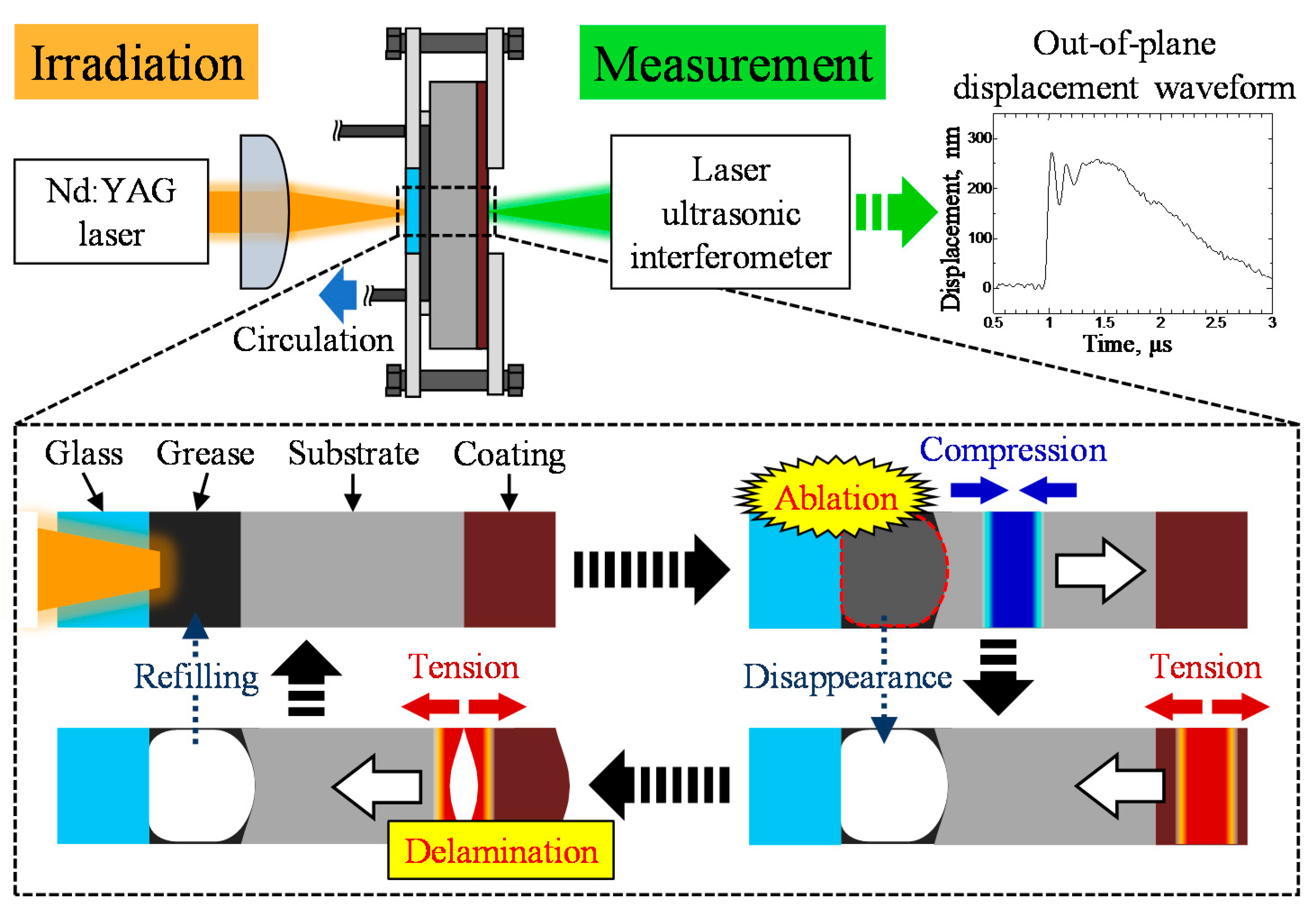
Figure 1 shows an overview of our LaSAT. Although a detailed explanation can be found in a previous work [18], we will summarize the method here. As shown in Figure 1, laser ablation was generated using an energy absorption layer (grease layer) formed on the back surface of the substrate. The thickness of the confined grease layer was 200 μm. A pulsed Nd:YAG laser (Tempest 300, New Wave Research, 1064 nm wavelength, 3–5 ns pulse duration, 2.3 mm laser diameter) was concentrated by a convex lens and irradiated into the grease layer in order to generate laser ablation. Because of the rapid volume expansion resulting from the laser ablation, a strong compressive elastic wave was excited on the back surface of the substrate. When this elastic wave propagated in the substrate and reached the coating’s free surface, free end reflection occurs, and a tensile-stress wave formed. This reflected tensile wave reached the interface again, resulting in the delamination of the coating. Simultaneously, an out-of-plane displacement waveform on the coating’s free surface was recorded by using a laser ultrasonic interferometer (Tempo-1D, Bossa Nova Technologies, 532 nm wavelength, continuous wave, 100 μm laser beam diameter). Using this waveform, we conducted a numerical simulation of the wave propagation to calculate the interfacial tensile stress. To detect the coating’s delamination, we used a previous method [24] in which the correlation coefficient for the out-of-plane displacement waveform on the coating surface was investigated to capture changes in the waveform resulting from delamination. The effectiveness of this method was demonstrated in previous research [18,24]. This method uses changes in the out-of-plane displacement waveform, which occurs when a material is delaminated. This is because the elastic wave reflects or diffracts at the delaminated interface. This method was verified by visually observing the cross section where delamination may or may not have occurred [18].
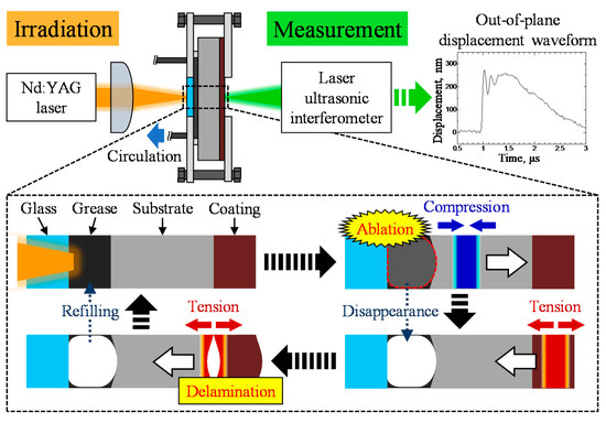
Figure 1.
Overview of laser shock-wave adhesion test (LaSAT).
2.2. Specimen
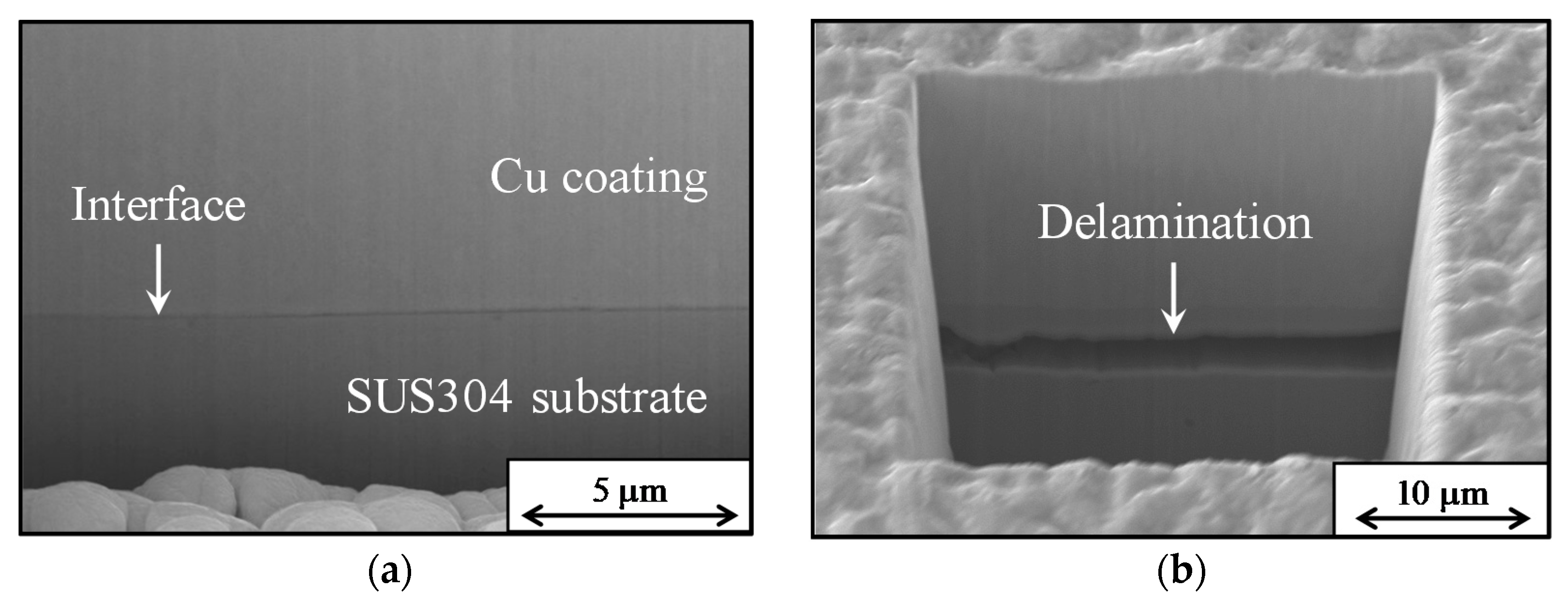
In this study, we used Cu plating as a model for interfacial materials such as films or coatings. Cu coating was deposited on a stainless-steel (SUS304) substrate using an electroplating method. Electroplating was performed using a copper sulfate bath as the plating bath and a phosphorus-containing copper plate as the cathode. Cu was deposited on the substrate surface in a layer with a thickness of 20 μm. The substrate was a flat plate with dimensions of 50 mm × 70 mm × 3 mm. After Cu deposition, a focused ion beam was used to remove the specimen surface, and the coating thickness was measured by observing the cross-sections using scanning electron microscopy (SEM). Figure 2 shows the results of cross-sectional observations before and after the LaSAT experiment [18]. Before laser irradiation, we observed sufficient adhesion between the coating and the substrate. By contrast, after the LaSAT, a clear delamination at the interface was observed. Table 1 shows the physical properties of the SUS304 substrate and the Cu coating. These properties were later used for the numerical simulation of elastic-wave propagation.
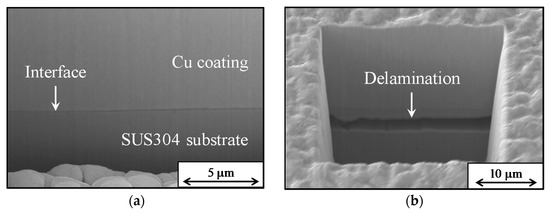
Figure 2.
SEM cross-sectional images of the specimen before (a) and after LaSAT (b) [18].

Table 1.
Material properties of stainless-steel (SUS304) substrate and electroplated Cu coating [18].
3. Results
3.1. Interfacial Crack Growth
3.1.1. Laser Ultrasonic Scanning (LUS)
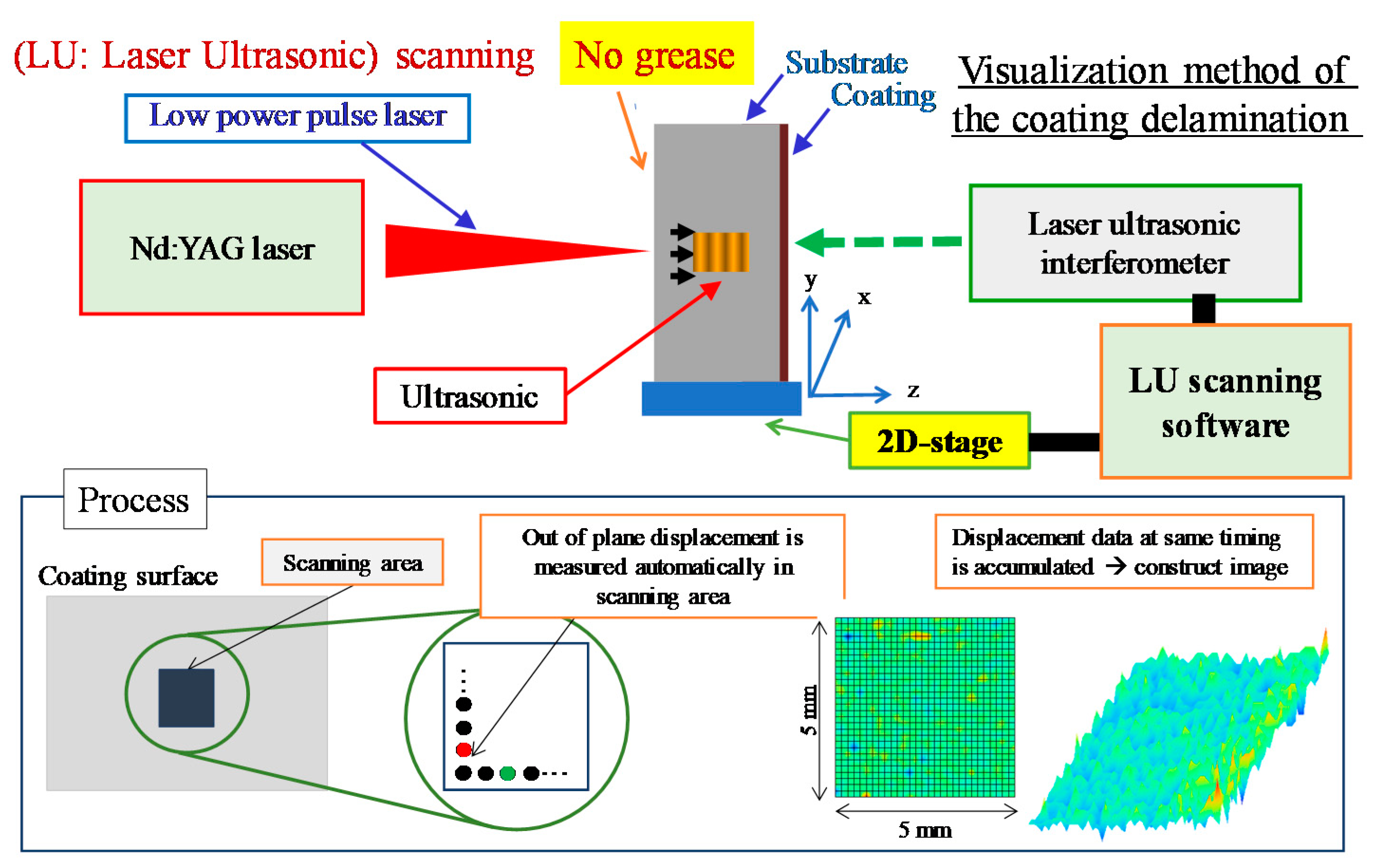
To evaluate interfacial fracture toughness, we conducted an experiment on interfacial crack growth, using LaSAT. We first introduced an initial interfacial crack (initial delamination) using LaSAT and then conducted additional LaSAT to enhance the initial crack growth (i.e., interfacial crack extension). Thus, it is necessary to identify the initial crack (delamination area) before additional LaSAT. However, the delamination area cannot be visually observed from the coating surface without destroying the material. Therefore, we used LUS [25] to nondestructively identify the delamination area. As shown in Figure 3, laser irradiation without grease was used to generate an elastic wave, and the wave was detected using a laser ultrasonic interferometer (out-of-plane velocity waveforms). The propagated elastic waves changed because of delamination (interfacial crack). This process of laser irradiation and wave detection were conducted multiple times to scan for in-plane motion using an automated X–Y stage. The scanning area was 5 mm × 5 mm on the coating surface. A total of 1600 pulsed lasers were irradiated throughout this area, and the out-of-plane velocity waveforms were acquired at each point of the coating surface. We previously reported that the reflection and diffraction of elastic waves at the delaminated interface caused a change in the wave propagation, resulting in a delaminated area that could be readily identified [25]. Therefore, changes in the waveform could be quantified using a correlation coefficient. When we obtained the out-of-plane velocity waveforms with correlation coefficient of 0.8 or less consecutively during scanning, we determined that delamination occurred at that point.
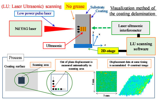
Figure 3.
Overview of LUS for delamination identification.
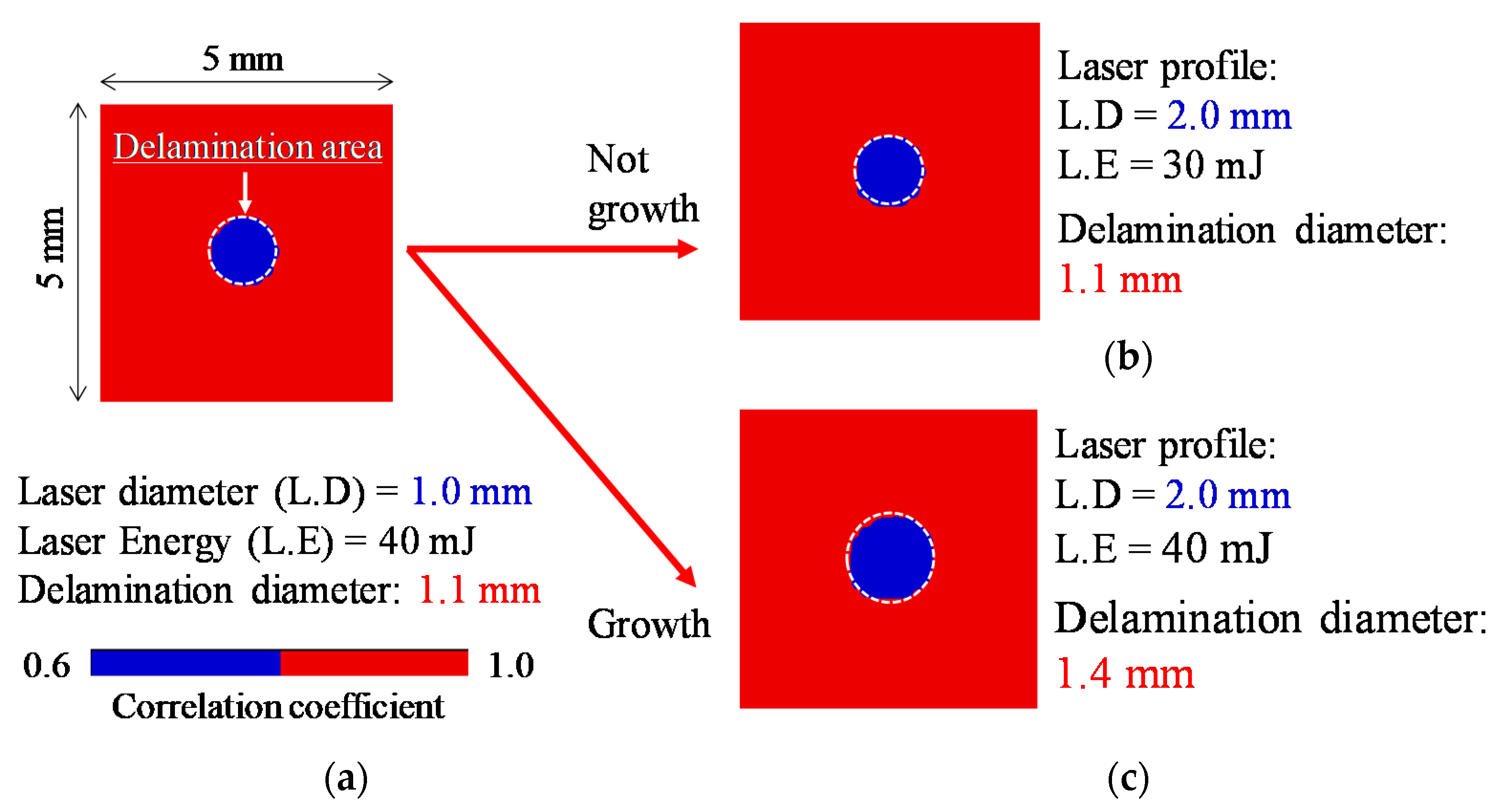
Figure 4 shows an example of interfacial crack growth test visualized by LUS. First, the specimen was irradiated with a single shot of the laser to create an initial delamination. Figure 4a shows the scanning result after irradiation with a laser having a diameter of 1.0 mm and a laser energy of 40 mJ. The blue area indicates the delamination area. We found that the delamination diameter was 1.1 mm. Next, we irradiated the same point again with a laser pulse to expand the delamination area (interfacial crack growth). This second irradiation was conducted using a single pulse of a laser having a diameter of 2 mm and a laser energy of 30 mJ. The result of LUS is shown in Figure 4b. Compared with Figure 4a, there was no change in the delamination diameter, suggesting no delamination growth. By contrast, Figure 4c shows that the delamination diameter increased when the experimental condition included a pulsed laser with a laser diameter of 2 mm and laser energy that was slightly little higher than 40 mJ. Therefore, the initial delamination, which was 1.1 mm in diameter, was increased by 300 µm to a final diameter of 1.4 mm when 40 mJ pulsed laser was used for irradiation. These results were then used for the numerical simulation, which was used to evaluate the interfacial fracture toughness.
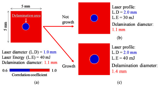
Figure 4.
Visualization of delamination area by LUS. (a) is initial delamination and (b,c) is result of additional LaSAT. Note that (b) shows no delamination growth and (c) is delamination growth.
3.1.2. FEM with Cohesive Zone Model (CZM)
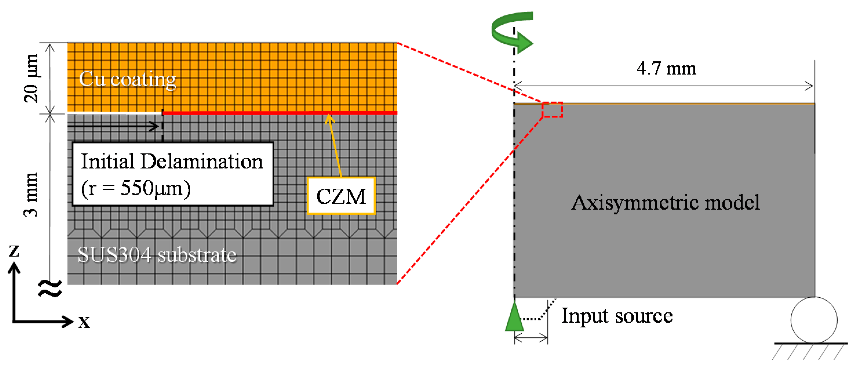
In LaSAT, elastic waves are usually reflected at the free surface of the coating and the interface with different acoustic impedances; this results in the complex interference of elastic waves. It is difficult to theoretically determine the interfacial stress, so we performed wave propagation simulations using the finite-difference time-domain method and FEM [18]. In this study, we created an FEM model as shown in Figure 5, in which the substrate thickness was 3 mm and the Cu coating thickness was 20 μm, as in the experiments. This axisymmetric model included fine meshes around the interface and coating. Here, minimum mesh size is 2.5 μm in this model. The material properties are shown in Table 1. In this model, an interfacial crack with a height of 550 nm and a radius of 550 µm (same dimensions as in the experiment shown in Figure 4a) was introduced at the interface for initial delamination. To simulate interfacial crack propagation, we used a CZM at the interface, as shown in Figure 5. In this study, we used the exponential form of the traction-separation law introduced by Smith–Ferrante as the cohesive force model; this form is typically used for film interfaces [26]. Equations (1) and (2) are equations for the energy release rate, GC, and the traction-separation law (exponential type) [26], respectively. Here, σmax is the maximum traction stress, VC is the crack opening displacement (COD) at σmax, KC is the fracture toughness used as stress intensity factor, and ν is Poisson’s ratio.

Figure 5.
Finite element method (FEM) model of coating and substrate with Cohesive Zone Model (CZM).
E and ν are elastic properties, also known as materials parameters. σmax is the interfacial strength (245 MPa), which was evaluated by LaSAT [18] in our previous study. According to the previous study [26], GC could be used to evaluate the fracture toughness KC.
To simulate the elastic wave from the laser ablation, the input source wave is required. In our model, the input source was a laser ablation excited by pulsed laser irradiation (see Figure 1). However, the physical phenomena of laser ablation are complex and difficult to evaluate experimentally. Therefore, we used the transfer function method to determine the input sources in the physical experiments by deconvolution. A detailed method for determining input waves was described in a previous study [27]. Here, we assumed that the energy distribution of the input sources had a trapezoidal shape by referring to the energy distribution of the Nd:YAG laser. This numerical approach can successfully evaluate the interfacial stress during LaSAT [18,27].
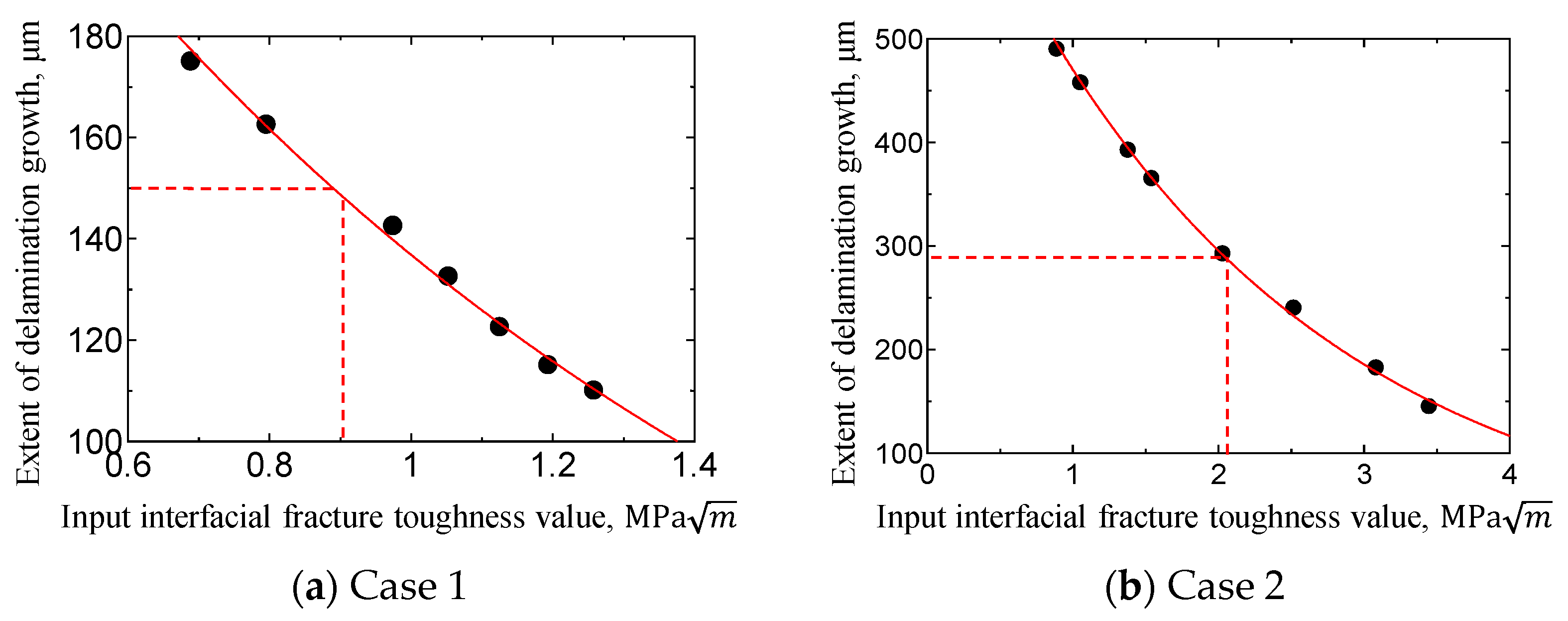
Using the method described above, this study simulated interfacial crack propagation to evaluate the interfacial fracture toughness. The computed interfacial crack growth is dependent on GC according to Equation (2). Thus, the interfacial fracture toughness Kc (converted from Equation (1)) varied from 0.69 to 1.26 MPa√m (Case 1) according to the parametric FEM computations. The computed results were compared with the delamination (interfacial crack) growth observed during LaSAT. Figure 6a shows the relationships between the input interfacial fracture toughness values and the extent of delamination growth (i.e., interfacial crack length). As shown Figure 4c, the extent of delamination was 150 μm as radius; we then determined the interfacial fracture toughness values of the Cu coating/stainless-steel (SUS304) substrate to be 0.91 MPa√m as plotted with red dash line (in Figure 6a). To ensure reproducibility, another LaSAT experiment (like the one shown in Figure 4) was conducted with additional laser energy of 60 mJ. In this experiment, the amount of delamination was 280 μm. Similarly, we conducted a parametric FEM study to simulate delamination growth, which we then compared with the experimental result (280 μm), as shown in Figure 6b. From this figure, we found that the interfacial fracture toughness was 2.14 MPa√m. The estimation was relatively scattered (0.91 MPa√m. and 2.14 MPa√m). We attributed the scattering to the brittle characteristics of the interface, since the interfacial strength ranged from 140 to 250 MPa [18]. Thus, we estimated the interfacial fracture toughness to be about 1.53 MPa√m (from 1 to 2 MPa√m). This value was similar to the values reported in previous studies [25,28].

Figure 6.
Relationships between the input interfacial fracture toughness value and the extent of delamination growth (a) Case1 and (b) Case 2.
3.2. Cyclic Irradiation Test
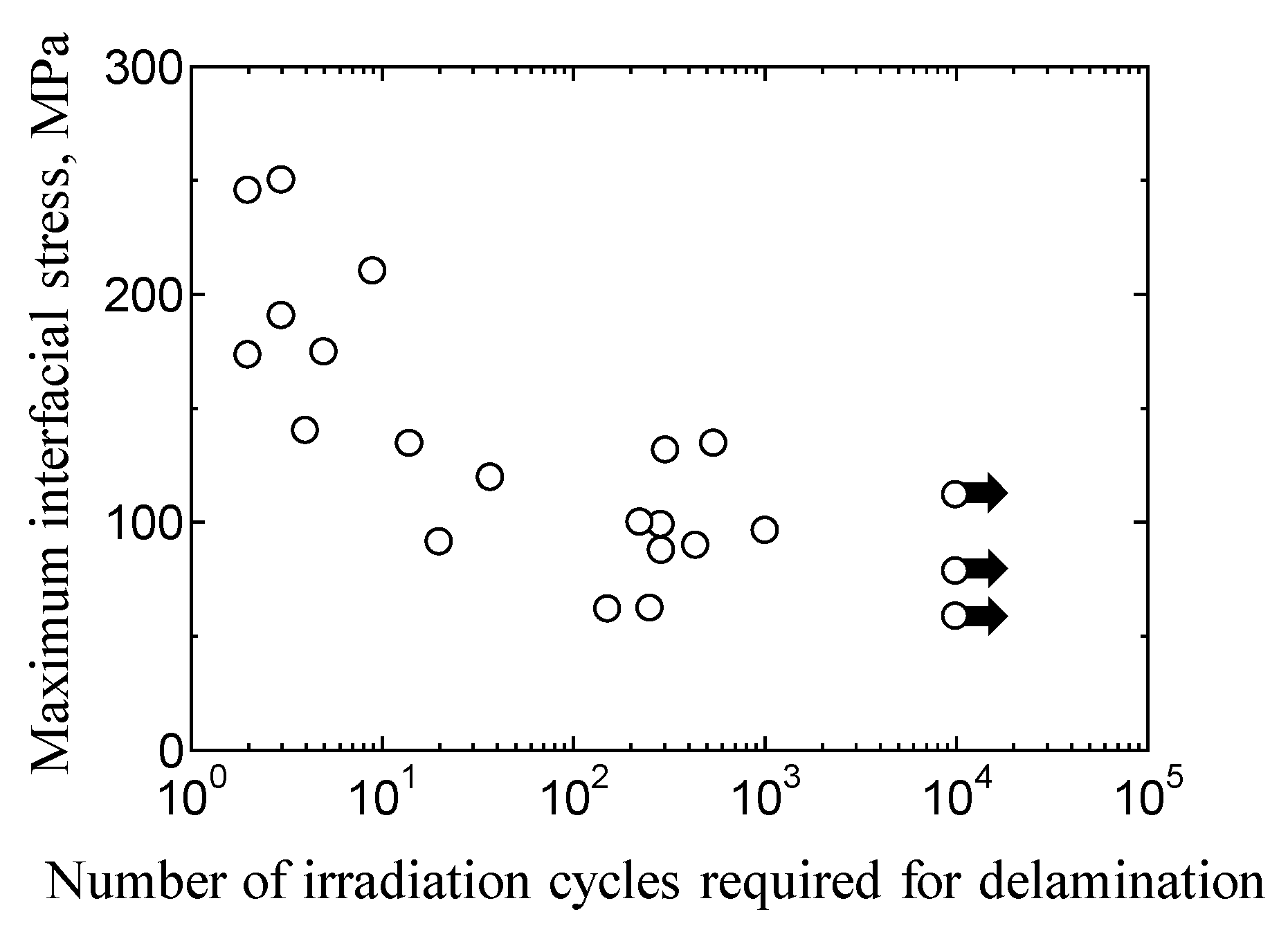
Similar to the interfacial strength evaluation test reported in Section 3.1 (Figure 1), we performed cyclic irradiation tests using LaSAT, called as repeated LaSAT [18]. This is a fatigue test used for evaluating interfacial strength and yielding adhesion durability. We showed the experimental setup and results of this method in a previous study [18] Repeated LaSAT was performed while the energy absorption layer (grease) was filled using a roller pump. The laser energy was changed from 40 to 70 mJ in order to vary the applied interfacial stress. The delamination initiation in the cyclic irradiation tests was determined from the correlation coefficient from the out-of-plane velocity waveform. Figure 7 shows the relationship between maximum interfacial stress (maximum tensile stress applied to the interface) and number of irradiation cycles required for delamination, including cracking (S–N curve). As shown in Figure 7, we also observed a tendency to reach fatigue in this test, in which the number of loading cycles required for fatigue delamination (crack) increased as the maximum tensile stress applied to the interface decreased. As described in the introduction, LaSAT is a spot experiment used to evaluate coating adhesion; the interfacial fracture initiates from the inside along the interface (not initiated from an interfacial edge). The mechanism of fatigue fracture in the interfacial case is unclear. To elucidate the fracture mechanism, we conducted MD simulation.

Figure 7.
Relationship between maximum interfacial stress and the number of irradiation cycles required for delamination in LaSAT [18].
4. MD Study
4.1. Crack Growth Simulation by MD
4.1.1. Simulation Condition
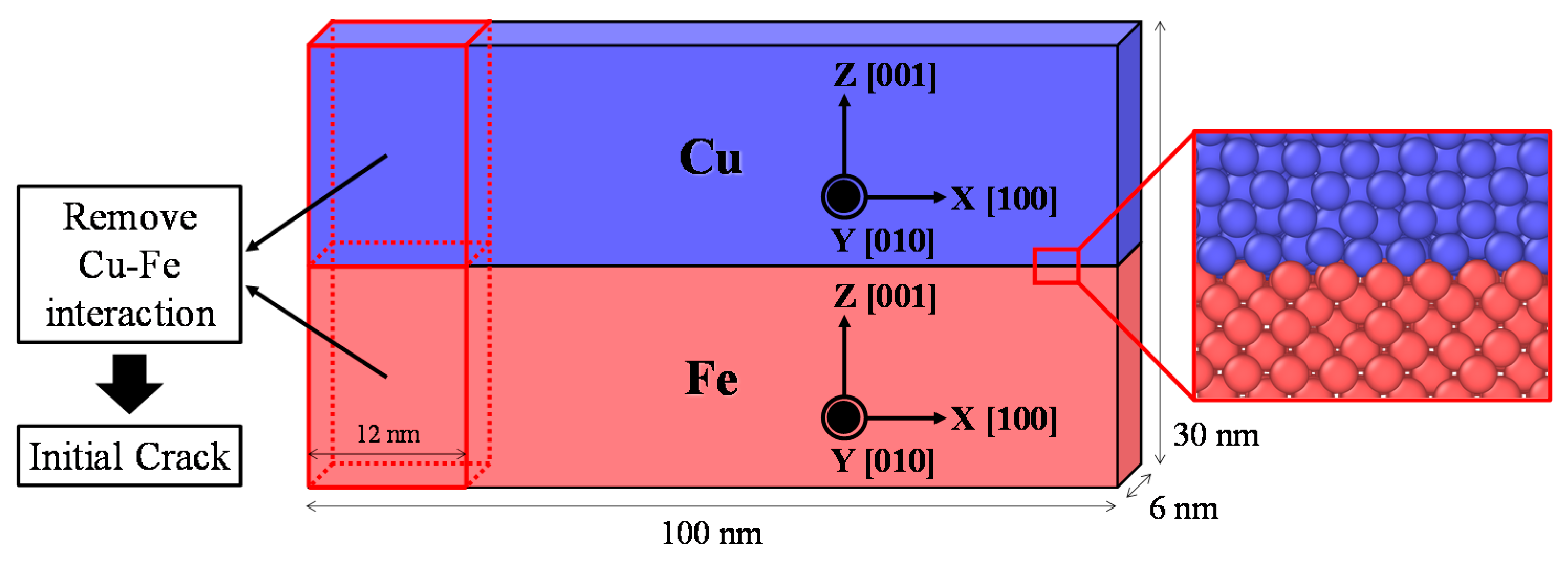
To elucidate the mechanisms for interfacial fracture during LaSAT, MD simulations were performed using the LAMMPS (Large Scale Atomic/Molecular Massively Parallel Simulator, Sandia National Laboratories, PA, USA) software package [29]. We performed this computation partially using the Exabyte.io platform, a web-based computational ecosystem for the development of new materials and chemicals [30]. Figure 8 shows an example of the Cu/Fe interface model (Model 1) used to simulate crack growth. The model dimensions are 100 nmL × 6 nmW × 30 nmH. Simulations were performed under plane strain conditions, in which the periodic boundary condition was applied in the Y-axis. In the X- and Z-directions, free boundary conditions were applied. The Cu model consisted of 781,694 atoms, and the Fe model consisted of 769,545 atoms in a crystal coordinate system with x [100], y [10], and z [1].
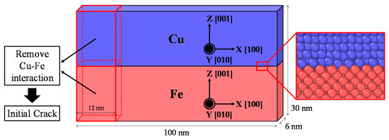
Figure 8.
Cu/Fe interface model used in delamination growth simulation (Model 1).
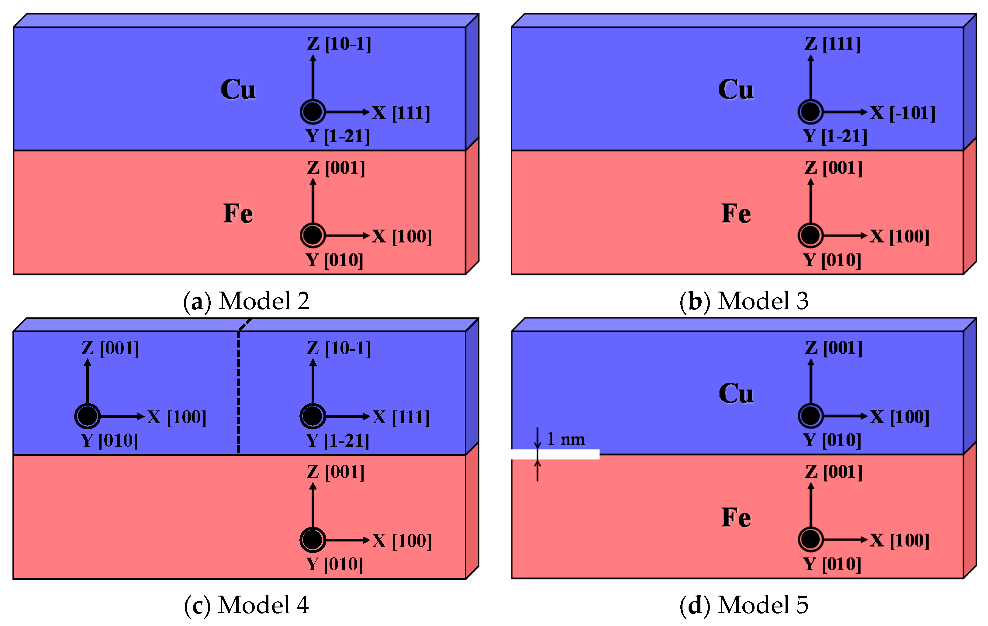
To investigate the effect of the crystalline orientation, grain boundary, and distance of crack surfaces, we also created different models (designated as Models 2, 3, 4, and 5) shown in Figure 9 to compare the deformation and crack propagation behavior among them. This is because the crystalline structure in the experimental conditions is unknown since Cu plating was conducted without controlling the crystal orientation (random orientation). To simulate interfacial pre-cracking in these models, the interactions between the Cu and Fe atoms in the region 12 nm from the interface edge (left) were removed, as shown in Figure 8. We used the Embedded Atom Method (EAM) potential proposed by Bonny et al. [31] as the interatomic potential.

Figure 9.
Other models with different crystal orientations (a,b), grain boundaries (c), and crack surfaces (d).
To reduce the number of strain mismatches near the interface of the interface models, we performed structural optimization using the conjugate gradient method, followed by a 50 ps relaxation in the NVT ensemble (constant number of atoms, cell volume, and temperature). Subsequently, uniaxial tensile loading simulations were performed by moving upward only the top constrained region of the model at a velocity of 30 m/s. Noted that the upper and lower parts within 0.5 nm from the model edge were constrained for the X- and Y-directions, and the upper part was moved upper direction (Z-direction).
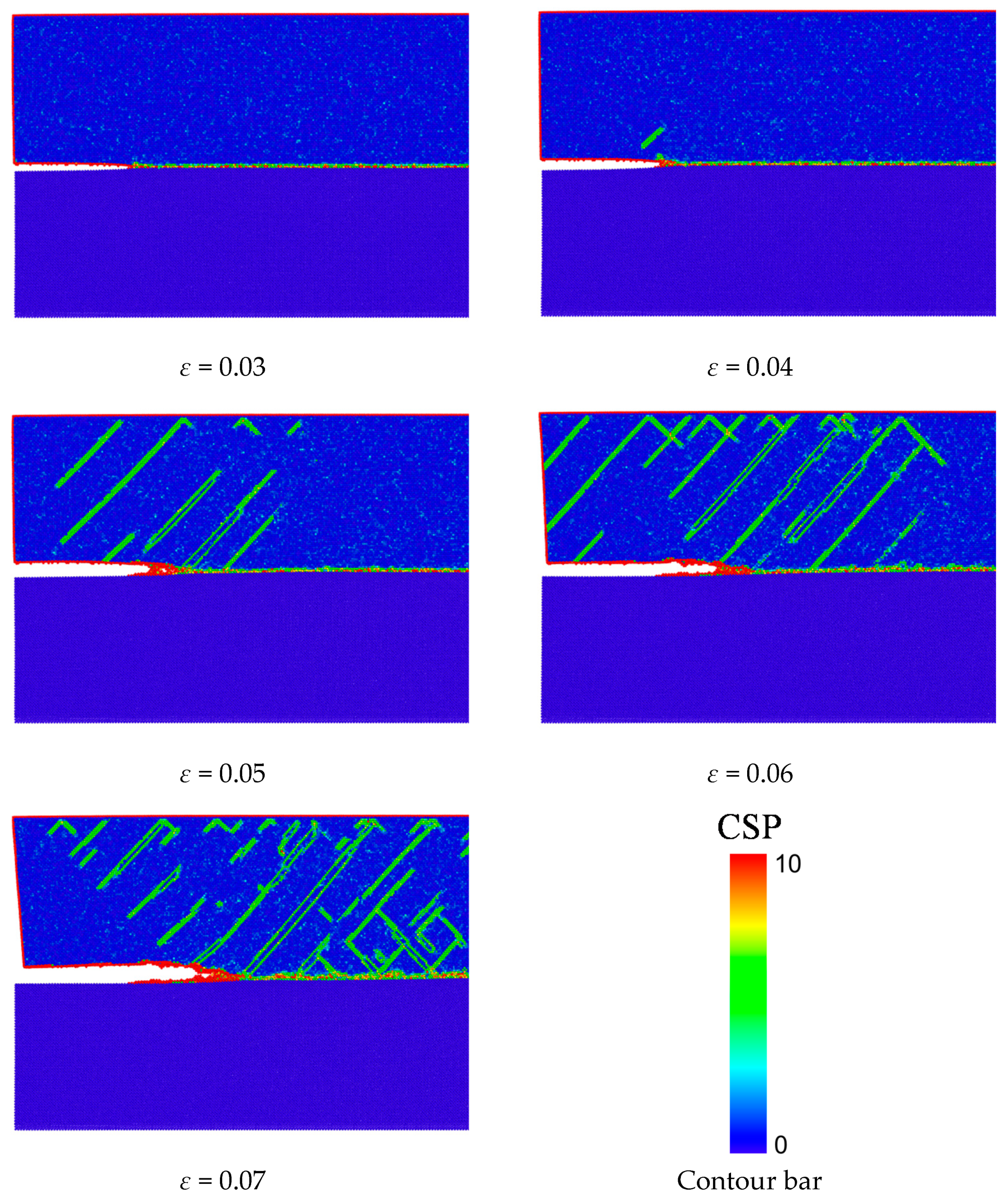
Figure 10 shows the contour diagram of the centro-symmetry parameter (CSP) [32] for tensile strains of 0.03, 0.04, 0.05, 0.06, and 0.07. CSP is represented by Equation (3), where N is the number of neighboring atoms, and r is the vector pointing from the central atom to each neighboring atom.

Figure 10.
Contour diagram of the CSP in Model 1.
The closer the crystalline structure is to a perfect crystal, the closer the CSP is to approaching zero. The CSP value becomes positive when the adjacent structures become non-periodic, such as in a dislocation, interface, or surface. From Figure 10, we found that the dislocations were emitted from the crack tip along about 45° direction toward the Cu layer ([111] direction) when the loading strain increased. These dislocations propagated in multiple directions with the growth of the interfacial crack. This stable interfacial crack propagation resulted in the final fracture of this model.
4.1.2. Estimation of Interfacial Fracture Toughness
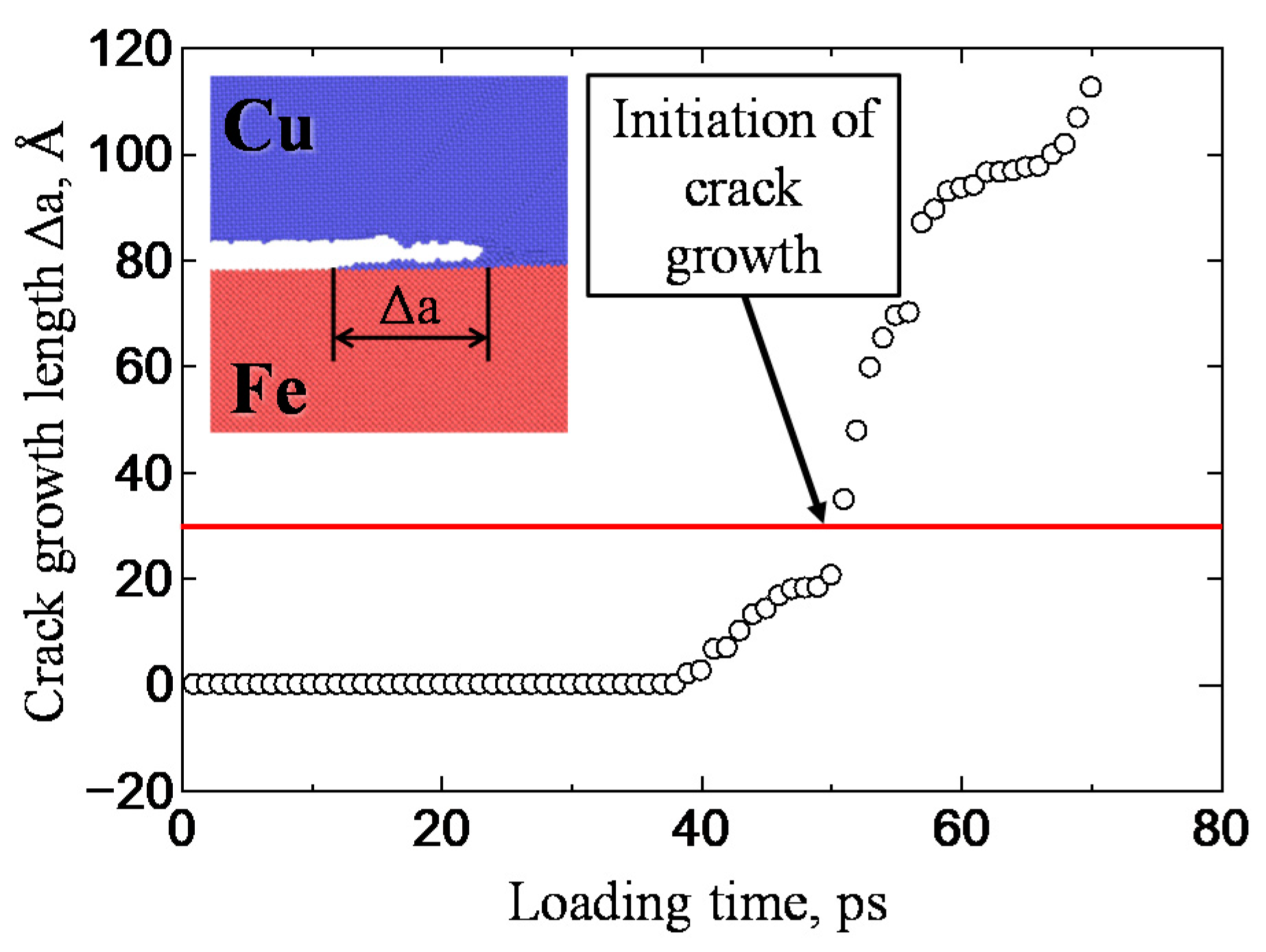
To verify our MD simulation model, the interfacial fracture toughness was estimated and quantitatively compared with the toughness obtained from the LaSAT experiment (Figure 6). To estimate the interfacial fracture toughness using MD simulation, we focused on the COD at the crack tip during crack growth in the MD simulations. Figure 11 shows the relationship between the loading time and crack growth length in Model 1 of Figure 8. Although it is difficult to define the timing of crack growth at an atomistic length scale, we assumed that crack propagation began when the initial crack growth reached 30 Å (∆a = 30 Å) because Figure 11 shows crack propagation remarkably after 30 Å. This is the critical timing for crack propagation, corresponding to interfacial fracture toughness (i.e., when the driving force reaches interfacial fracture toughness, crack propagation starts).
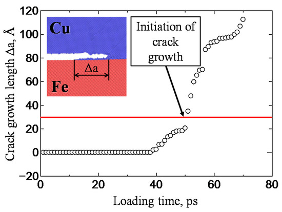
Figure 11.
Relationship between loading time and crack growth length in Model 1.
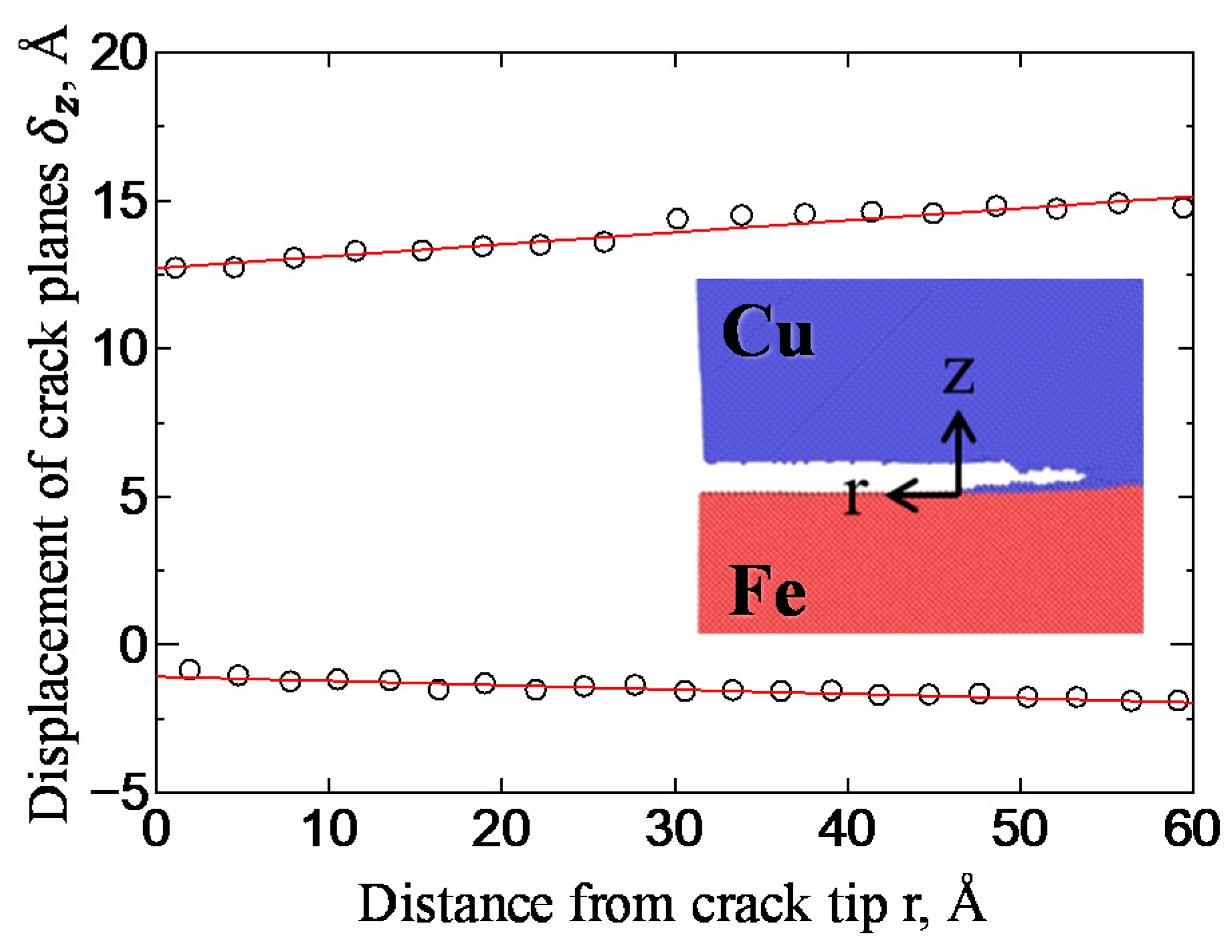
Figure 12 shows the crack tip shape at the beginning of crack growth. The crack shape (COD along the Z-direction) is plotted along the interface. The relative opening displacements of the crack surface (δx and δz for the X- and Z-directions, respectively) were obtained around the crack tip. As shown by the red line in Figure 12, the COD at the crack tip could be obtained. From the COD (Figure 12), the interfacial fracture toughness was calculated using the displacement extrapolation method proposed by Yuuki et al. [28]. The extrapolation equations for the stress intensity factor are shown as Equations (4) and (5):
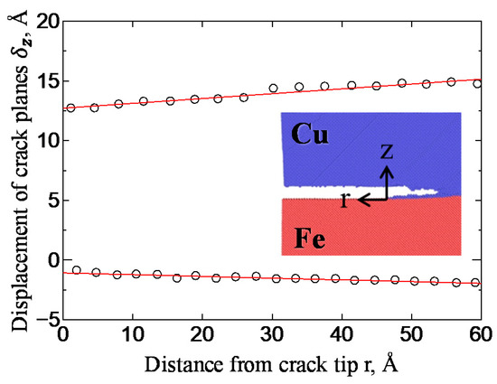
Figure 12.
Crack shape at initiation of crack growth.
Here, KI and KII are the stress intensity factors in mode I and mode II, respectively; C and ε are constants determined by the Poisson’s ratio and the shear modulus of each material; and Q is a function expressed by ε and the distance r from the crack tip. Table 2 shows the fracture toughness values for each model in the MD simulation estimated using Equations (4)–(6). The fracture toughness values obtained by MD simulations ranged from 1.59 to 2.97 MPa√m, which is comparable to the fracture toughness values obtained by LaSAT as mentioned above. This suggests that the delamination growth at the interface was dominated by the local plastic deformation of a nanometer-scale small region around the crack tip. Our MD simulations were thus verified with the experimental results.

Table 2.
Fracture toughness values for each model in the molecular dynamics (MD) simulation.
4.2. Fatigue Loading Simulation
4.2.1. Simulation Condition
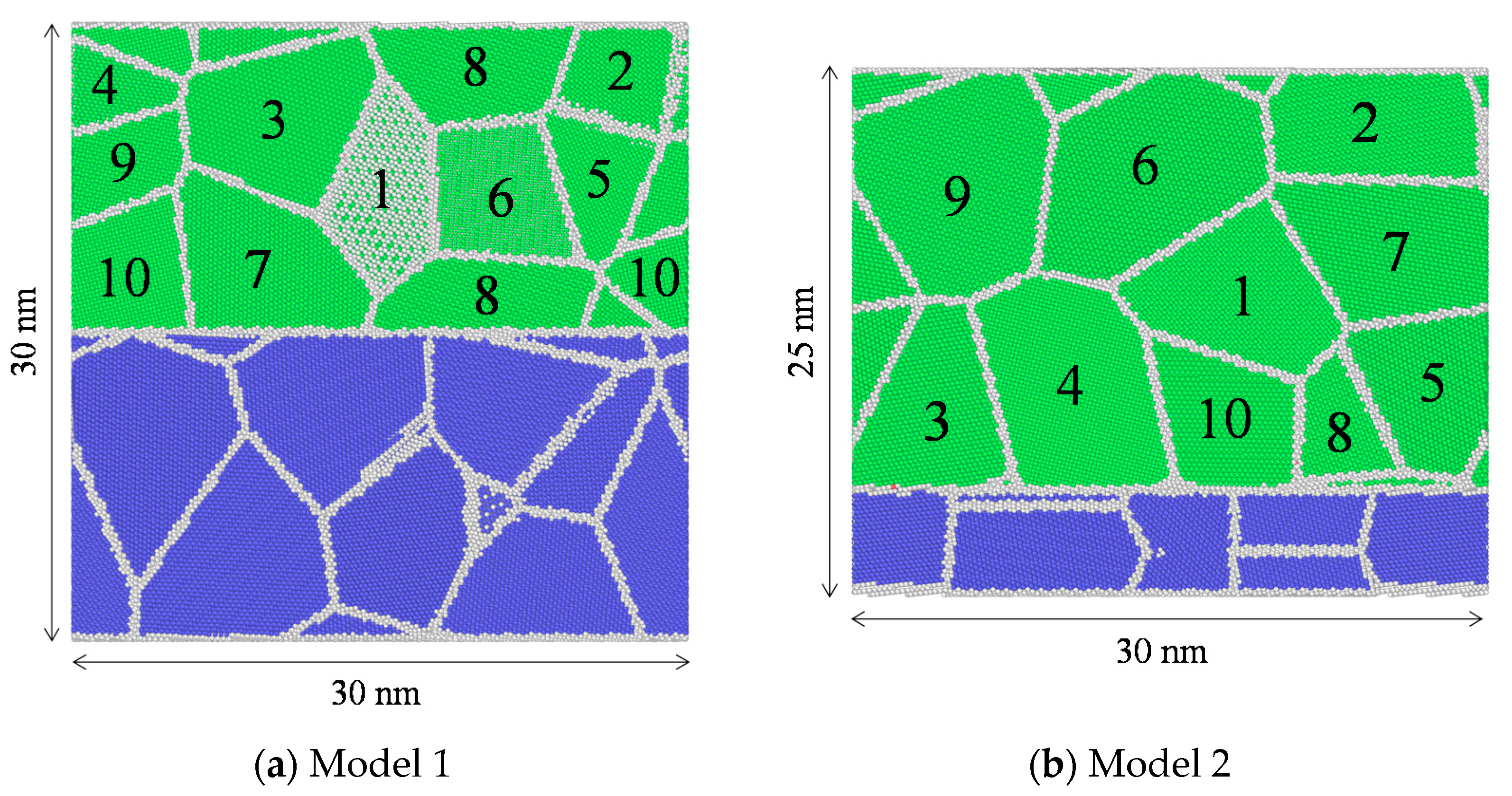
Next, fatigue loading simulations were performed using MD to investigate the mechanism for interfacial fatigue fracture, which was experienced during LaSAT (Figure 7). Figure 13 shows two types of interfacial models, which were created using Atomsk [33]. In this study, we created a crystalline model, which mimicked the random crystalline structure (representing the conditions of the experiment). Model 1 consisted of 10 grains in both the Cu and Fe layers, while Model 2 consisted of 10 and 4 grains in the Cu and Fe layers, respectively. The dimensions of both models were 30 nmL × 6 nmW × 30 nmH. The periodic boundary conditions were applied in the X- and Y-directions, and free boundary condition was applied in the Z-direction; this resulted in an infinite bi-material model without interface edges. The numbers shown in Figure 13 are used for the identification of each grain. Table 3 lists the maximum Schmidt factor (MSF) for each grain and slip system for both models. MSFs with large absolute values are shown in red letters.
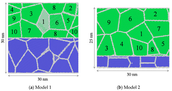
Figure 13.
Two types of interfacial models for fatigue fracture.

Table 3.
Maximum Schmidt factor (MSF) in each grain and slip system, which takes the MSF in Model 1 (a) and Model 2 (b). MSFs with large absolute values are shown in red letters.
In order to obtain stable structures for the interface models, we performed a structural optimization using the conjugate gradient method, followed by a 50 ps relaxation in the NPT ensemble (constant number of atoms, cell pressure, and temperature). The model was loaded according to the same conditions reported in Section 4.1, but when the tensile stress in the model reached the set maximum tensile stress, the tensile loading was released. During unloading, the tensile stress in the model reached the set minimum tensile stress, and tensile deformation began again. This process is known as stress-controlled cyclic (fatigue) loading.
The grain size of MD simulation was different from that in the physical experiment because of model size limitations. However, the purpose of this study is to elucidate the fracture mechanism and not to quantitatively compare the MD simulation and LaSAT.
4.2.2. Simulation Results
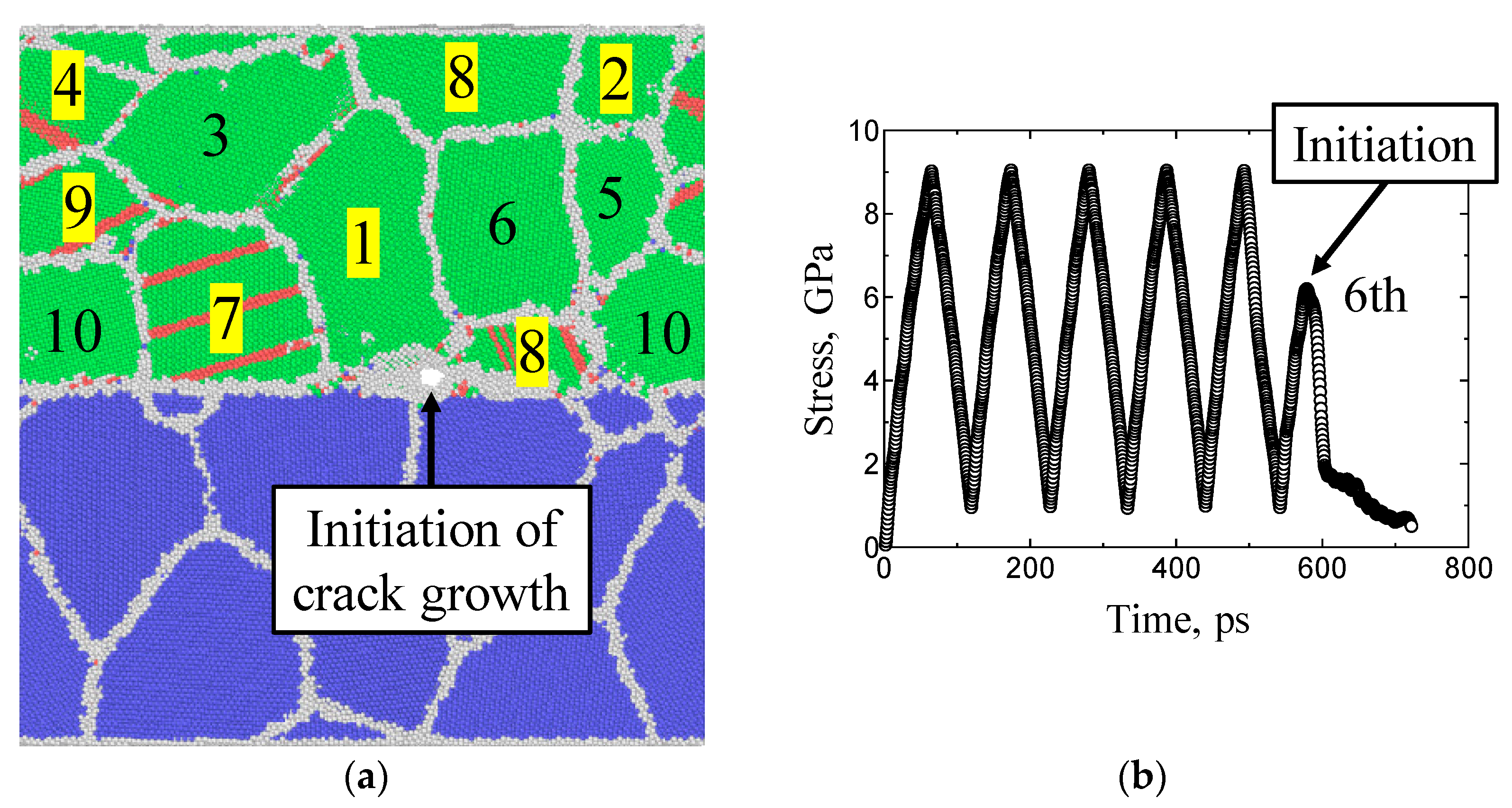
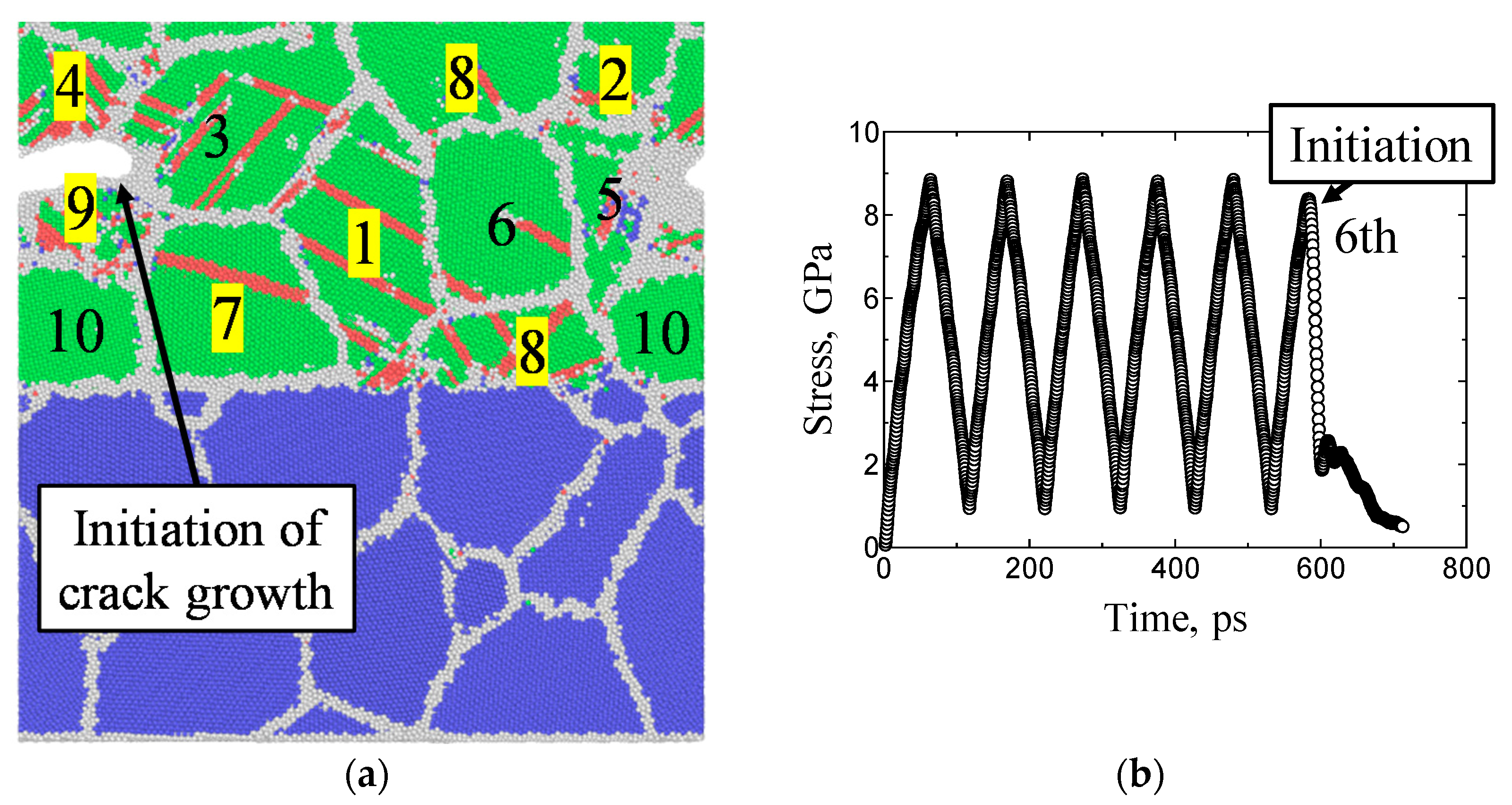
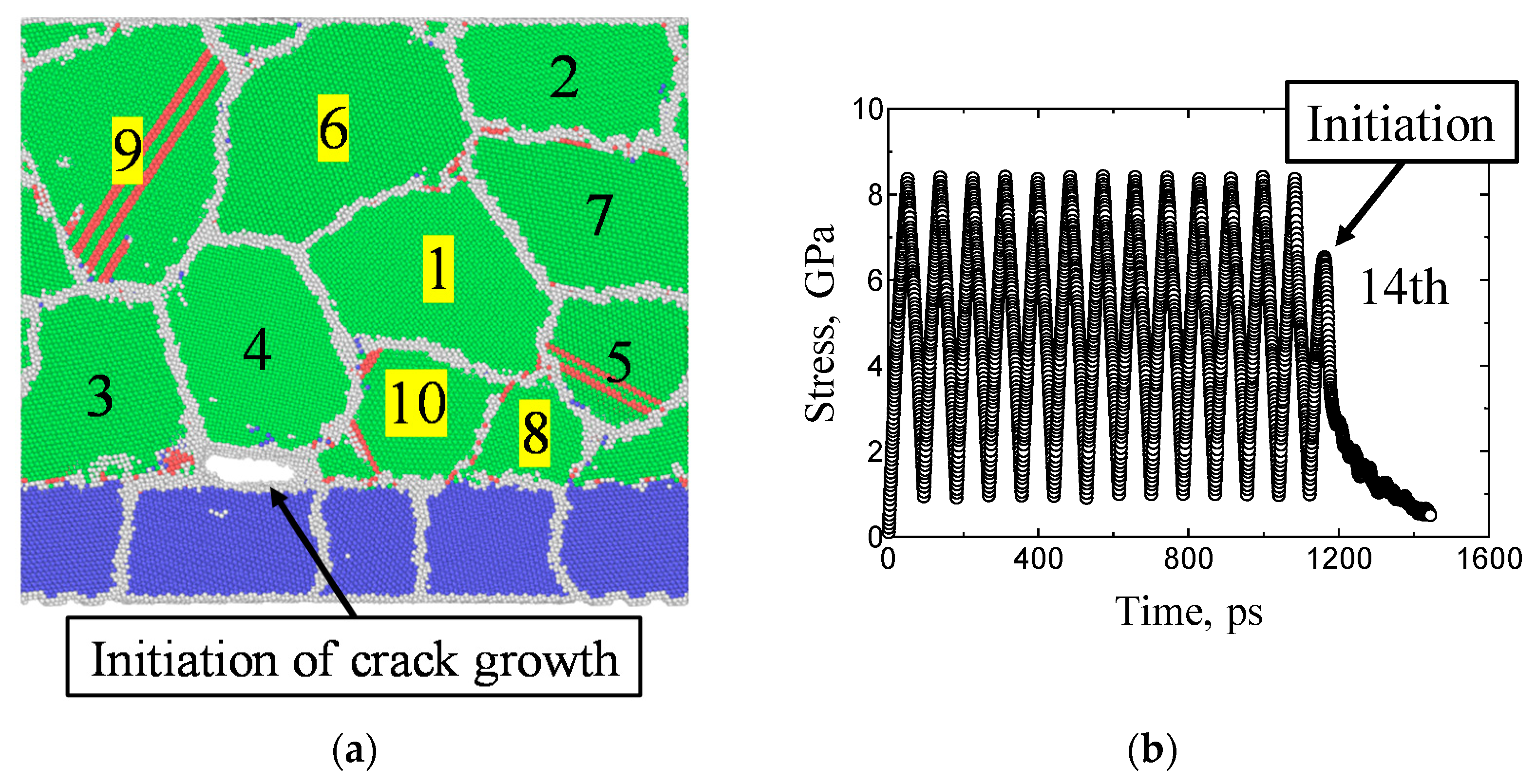
Figure 14 shows a snapshot of Model 1 at the initiation of crack growth (Figure 14a) and the transition of stress during loading (Figure 14b) when the maximum tensile stress of 9.00 GPa was repeatedly applied until the initiation of cracking. In Figure 14a, the dislocation generated regions as determined from CSP are shown in red, and the grain numbers with high absolute MSF (in Table 3) are highlighted in yellow. Figure 14b shows that a crack initiated at the grain boundary between grains No. 1 and No. 8 during the sixth tensile loading. Similarly, Figure 15 shows a snapshot of Model 1, in which a maximum tensile stress of 8.80 GPa was repeatedly applied. Figure 15b shows that a crack initiated at the grain boundary between grains No. 4 and No. 9 during the sixth tensile loading.

Figure 14.
Snapshot at the time of fatigue crack initiation (a) and the transition of stress during cyclic loading (b) when a maximum tensile stress of 9.00 GPa was applied to Model 1.
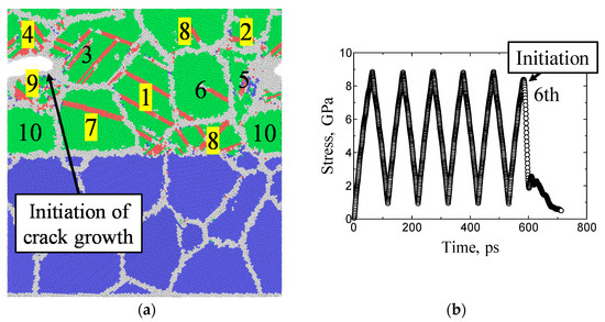
Figure 15.
Snapshot at the time of fatigue crack initiation (a) and transition of stress during cyclic loading (b) when a maximum tensile stress of 8.80 GPa was applied to Model 1.
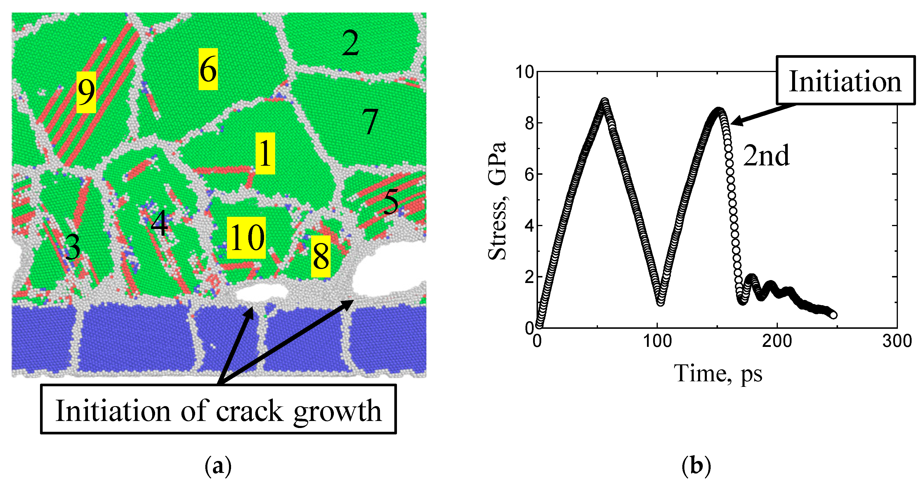
Figure 16 shows a snapshot of Model 2, to which a maximum tensile stress of 8.80 GPa was repeatedly applied, and Figure 16b shows that cracks initiated at the grain boundaries between grains No. 3 and No. 5 and between grains No. 8 and No. 10 during the second tensile loading. Figure 17 shows a snapshot of Model 2 when a maximum tensile stress of 8.35 GPa was repeatedly applied, and Figure 17b shows that cracks initiated at the grain boundary between grains No. 3 and No. 4 and between grains No. 4 and No. 10 during the 14th tensile loading. From Figure 14a, Figure 15a, Figure 16a and Figure 17a, it can be seen that in the grains for which the absolute MSF was high (highlighted in yellow), dislocations preferentially occurred and reached the grain boundaries. In addition, we found that the number of loading cycles to fracture changed according to the applied maximum tensile stress.
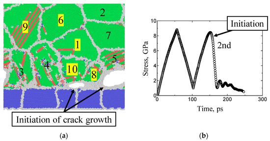
Figure 16.
Snapshot at the time of fatigue crack initiation (a) and transition of stress during cyclic loading (b) when a maximum tensile stress of 8.80 GPa was applied to Model 2.
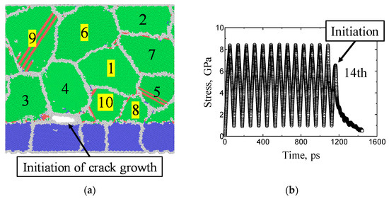
Figure 17.
Snapshot at the time of fatigue crack initiation (a) and transition of stress during cyclic loading (b) when a maximum tensile stress of 8.35 GPa was applied to Model 2.
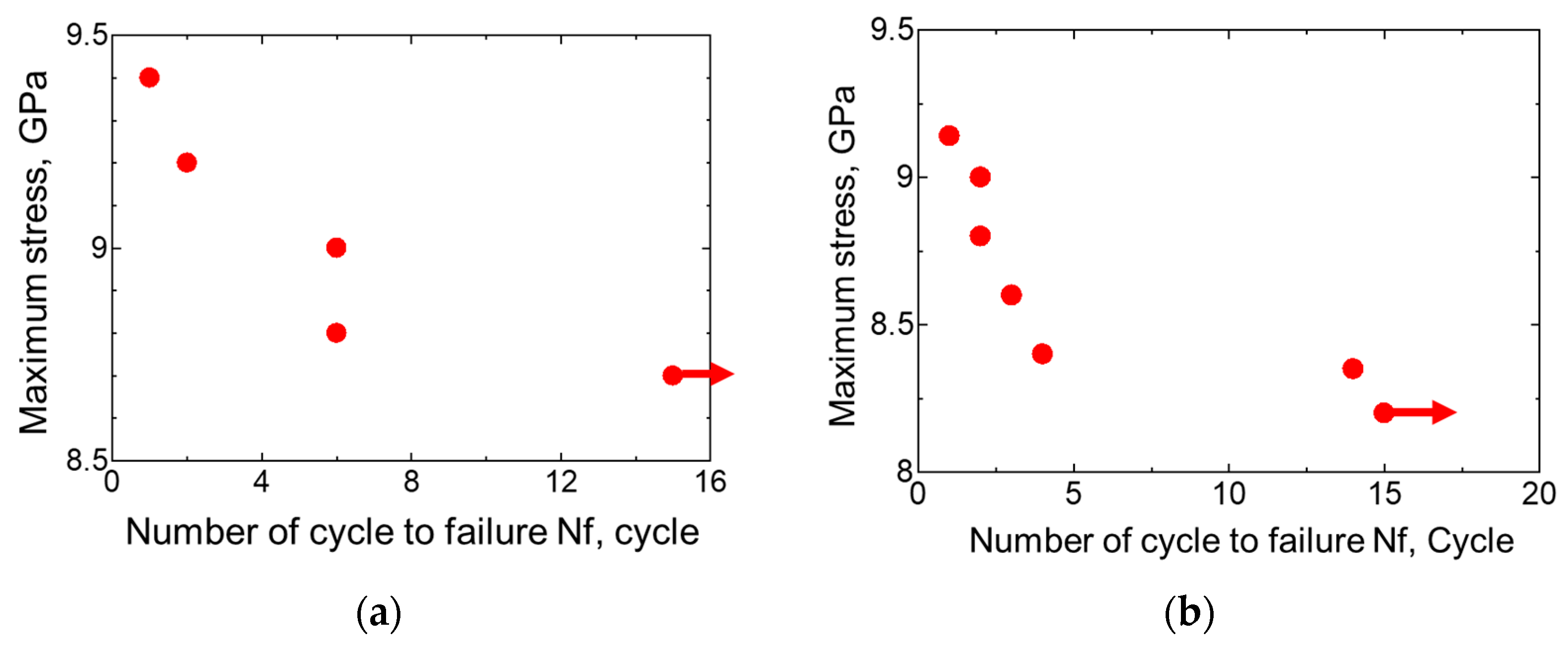
Similarly, fatigue loading simulations were conducted under various conditions to investigate the relationship between maximum tensile stress (interfacial strength) and the number of loading cycles required for crack initiation. Figure 18 shows the relationship between interfacial strength and the number of loading cycles required for crack initiation (S–N curve, Wöhler curve) according to MD. A clear fatigue trend could be observed, namely, the number of loading cycles to crack initiation tended to increase with lower maximum tensile stress values. This trend is similar to the experimental results obtained using LaSAT shown in Figure 7. As shown in Figure 13, this interfacial polycrystalline model does not include an interfacial edge; rather, an interfacial crack initiated inside the material along the interface (in Figure 14, Figure 15, Figure 16 and Figure 17).

Figure 18.
Relationship between interfacial strength and the number of loading cycles required for crack initiation in Model 1 (a) and Model 2 (b) according to MD simulations.
4.2.3. Discussion
From these results, we discuss the mechanism of fatigue fracture, i.e., fatigue crack initiation, for a polycrystalline interface model without interface edges. Table 3 and Figure 14a, Figure 15a, Figure 16a and Figure 17a show that even during macroscopic elastic deformation in the Cu coating, some grains showed plastic deformation, since slip deformation in some grains was preferentially active due to a higher MSF (attributed to the difference in resistance to plastic deformation from each grain at the microscopic level). This is due to the random polycrystalline structure. Subsequently, dislocations nucleate in the grains and reach the grain boundary, resulting in an accumulation at the grain boundaries. Because of an accumulation in the dislocations and the larger dislocation density, grain boundary become a source of stress concentration, resulting in the initiation of fatigue cracks. We indeed discovered dislocations in many grains under a large stress (Figure 16a). By contrast, under the small stress shown in Figure 17a, dislocation nucleation only occurred in some grains. This suggests that even under a relatively small stress, dislocations gradually accumulate at grain boundaries and interface under cyclic loading, resulting in fatigue fracture. Therefore, our MD simulation clarifies that repeated LaSAT produces fatigue crack initiation around the interface, resulting in interfacial fatigue fracture.
As shown in Figure 13, the microstructure of MD simulation model is not completely same with the actual material (Cu coating on SUS304). Due to a limitation of MD simulation, actual size and actual internal structure of material cannot be created accurately, since many factors (i.e., solute atoms, defect, dislocation, grain boundary) should be considered. Thefore, we created a simple model, having a typical polycrystalline structure in the MD model as shown in Table 3. We clearly found that crystalline structure of Cu coating plays a key role of fatigue crack initiation around the interface. Thus, interfacial edge is not necessary for interfacial fatigue crack initiation, which is the same phenomenon in our LaSAT experiment. This indicates that our simple model of MD simulation predicts the physical mechanism of interfacial fatigue crack initiated by LaSAT experiment. However, as shown in Figure 18, stress level and fatigue life are different from the experiment (Figure 7). One main reason is the sample size, i.e., macroscopic experiment vs. nanoscopic simulation. In other words, our MD simulation focuses on ultrasmall region around the interface in order to elucidate the physical mechanism of fatigue crack initiation. Thus, we cannot predict fatigue failure life from our MD simulation. This will be addressed in the future.
5. Conclusions
This study quantitatively evaluated the interfacial strength and durability of Cu plate coating, using the LaSAT. The fatigue failure mechanisms were elucidated with MD simulations. The findings are summarized below.
- (1)
- To evaluate interfacial fracture toughness, delamination growth tests for a Cu plate on SUS substrate were conducted using LaSAT. First, an initial delamination was created using LaSAT, and an additional LaSAT was conducted to enhance the initial delamination growth. The delamination area could be visualized non-destructively using LUS. FEM computation was carried out to compute the interfacial stress due to LaSAT. In addition, a CZM was used to estimate Kc.
- (2)
- Repeated LaSAT was conducted to evaluate the adhesion durability of Cu coating. The tests were performed at various laser energies to investigate the number of loading cycles required for delamination. The results indicated a fatigue fracture tendency similar to that of a common homogeneous metal material: The coating life of delamination increased as the applied stress decreased.
- (3)
- Using MD simulations of the Cu/Fe interface, we calculated the interfacial fracture toughness using the displacement extrapolation method. The interfacial fracture toughness ranged from 1.6 to 3.0 MPa√m, values that are comparable to those calculated from the LaSAT experiment, 0.91 MPa√m and 2.0 MPa√m. This suggests that the delamination growth at the interface is dominated by local plastic deformation in a small region on the nanometer scale around the crack tip. In addition, we verified our MD simulation from the LaSAT experiments.
- (4)
- MD simulations were also done to perform stress-controlled cyclic loadings in a Cu/Fe interfacial polycrystalline model. This model was an infinite-flat-plate interface model without interface edges. Unlike conventional fatigue mechanisms, the model did not induce any intrusion or extrusion. Even in the interface model, we found that the accumulation of microscopic plastic deformations (dislocations) in each grain resulted in fatigue fracture.
- (5)
- We found that there are active grains that preferentially slip, and dislocations in the grains propagate up toward the grain boundaries and/or interface. This results in an accumulation of dislocations, increasing the dislocation density. Therefore, a source of stress concentration forms, resulting in the initiation of fatigue cracks. Thus, interfacial fatigue cracks may initiate from the inside along the interface, and interfacial edges are not always necessary for interfacial fatigue fracture.
Author Contributions
K.K. and S.T. developed the theoretical background and performed the MD simulations. Y.K. performed experiments. K.K. and A.Y. took the lead in writing the manuscript. A.Y. supervised the project. All authors have read and agreed to the published version of the manuscript.
Funding
This work is supported by The Amada Foundation (grant no. AF-2017023) and JSPS KA-KENHI (grant no. 20K20966) from the Japan Society for the Promotion of Science.
Institutional Review Board Statement
Not applicable.
Informed Consent Statement
No applicable.
Data Availability Statement
Data available on request due to restrictions.
Conflicts of Interest
The authors declare no conflict of interest.
References
- Li, N.; Jia, R.; Zhang, H.; Sha, W.; Li, Y.; Jiang, Z. In-situ Cu Coating on Steel Surface after Oxidizing at High Temperature. Materials 2019, 12, 3536. (In English) [Google Scholar] [CrossRef] [PubMed]
- Fukumoto, S.; Ohta, K.; Yanagimoto, T.; Kashiba, Y.; Kikuchi, M.; Matsushima, M.; Fujimoto, K. Characteristics and Microstructural Development of Cold-Sprayed Copper Coating on Aluminum. Mater. Trans. 2019, 60, 602–610. [Google Scholar] [CrossRef]
- Wan, Y.; Hu, X.; Xu, T.; Li, Y.; Jiang, X. Interfacial IMC growth of SAC305/Cu joint with a novel dual-layer of Ni(P)/Cu plating during solid-state aging. Microelectron. Eng. 2018, 199, 69–79. [Google Scholar] [CrossRef]
- Yang, L.; Atanasova, T.; Radisic, A.; Deconinck, J.; West, A.C.; Vereecken, P. Wafer-scale Cu plating uniformity on thin Cu seed layers. Electrochim. Acta 2013, 104, 242–248. [Google Scholar] [CrossRef]
- Lee, P.T.; Wu, Y.S.; Lin, P.C.; Chen, C.C.; Hsieh, W.Z.; Ho, C.E. High-speed Cu electrodeposition and its solderability. Surf. Coat. Technol. 2017, 320, 559–567. [Google Scholar] [CrossRef]
- Watanabe, M.; Kuroda, S.; Yokoyama, K.; Inoue, T.; Gotoh, Y. Modified tensile adhesion test for evaluation of interfacial toughness of HVOF sprayed coatings. Surf. Coat. Technol. 2008, 202, 1746–1752. [Google Scholar] [CrossRef]
- Dayani, S.B.; Shaha, S.K.; Ghelichi, R.; Wang, J.F.; Jahed, H. The impact of AA7075 cold spray coating on the fatigue life of AZ31B cast alloy. Surf. Coat. Technol. 2018, 337, 150–158. [Google Scholar] [CrossRef]
- Piveteau, L.-D.; Gasser, B.; Schlapbach, L. Evaluating mechanical adhesion of sol–gel titanium dioxide coatings containing calcium phosphate for metal implant application. Biomaterials 2000, 21, 2193–2201. [Google Scholar] [CrossRef]
- Mead, J.L.; Lu, M.; Huang, H. Inducing stable interfacial delamination in a multilayer system by four-point bending of microbridges. Surf. Coat. Technol. 2017, 320, 478–482. [Google Scholar] [CrossRef]
- Hirakata, H.; Kitazawa, M.; Kitamura, T. Fatigue crack growth along interface between metal and ceramics submicron-thick films in inert environment. Acta Mater. 2006, 54, 89–97. [Google Scholar] [CrossRef]
- Ito, H.; Kiminami, S.; Cho, H. Evaluation of adhesion quality of oxide scale on low carbon steel at high temperature using a laser spallation technique. Trans. JSME 2015, 81, 14-00493. (In Japanese) [Google Scholar] [CrossRef]
- Mittal, K.L. Adhesion Measurement of Thin Films, Thick Films, and Bulk Coatings; ASTM International: West Conshohocken, PA, USA, 1978. [Google Scholar]
- Yuan, J.; Gupta, V. Measurement of interface strength by the modified laser spallation technique. I. Experiment and simulation of the spallation process. J. Appl. Phys. 1993, 74, 2388–2396. [Google Scholar] [CrossRef]
- Berthe, L.; Arrigoni, M.; Boustie, M.; Cuq-Lelandais, J.P.; Broussillou, C.; Fabre, G.; Jeandin, M.; Guipont, V.; Nivard, M. State-of-the-art laser adhesion test (LASAT). Nondestruct. Test. Eval. 2011, 26, 303–317. [Google Scholar] [CrossRef]
- Bolis, C.; Berthe, L.; Boustie, M.; Arrigoni, M.; Barradas, S.; Jeandin, M. Physical approach to adhesion testing using laser-driven shock waves. J. Phys. D Appl. Phys. 2007, 40, 3155–3163. [Google Scholar] [CrossRef]
- Bégué, G.; Fabre, G.; Guipont, V.; Jeandin, M.; Bilhe, P.; Guedou, J.Y.; Lepoutre, F. Laser Shock Adhesion Test (LASAT) of EB-PVD TBCs: Towards an industrial application. Surf. Coat. Technol. 2013, 237, 305–312. [Google Scholar] [CrossRef]
- Arrigoni, M.; Kruger, S.E.; Blouin, A.; Lévesque, D.; Arsenault, B.; Monchalin, J.P.; Boustie, M.; Berthe, L. Adhesive Bond Testing By Laser Induced Shock Waves. In Proceedings of the 17th World Conference on Nondestructive Testing, Shanghai, China, 25–28 October 2008. [Google Scholar]
- Kanamori, K.; Saito, Y.; Yamada, T.; Yonezu, A.; Chen, X. Development of Adhesion Durability Evaluation of Surface Coatings Using Repeated Laser Shock-wave Adhesion Test. J. Nondestruct. Eval. 2020, 39, 87. [Google Scholar] [CrossRef]
- Ostrowicki, G.T.; Sitaraman, S.K. Cyclic magnetic actuation technique for thin film interfacial fatigue crack propagation. Eng. Fract. Mech. 2016, 168, 1–10. [Google Scholar] [CrossRef]
- Lin, P.; Shen, F.; Yeo, A.; Liu, B.; Xue, M.; Xu, H.; Zhou, K. Characterization of interfacial delamination in multi-layered integrated circuit packaging. Surf. Coat. Technol. 2017, 320, 349–356. [Google Scholar] [CrossRef]
- Yashiro, K.; Nimura, K.; Naito, K. Molecular Dynamics Study on Adhesion of Various Ni/Al Interface for Ni-Plated Aluminum Alloys. Mater. Trans. 2018, 59, 1753–1760. [Google Scholar] [CrossRef]
- Ma, L.; Xiao, S.; Deng, H.; Hu, W. Molecular dynamics simulation of fatigue crack propagation in bcc iron under cyclic loading. Int. J. Fatigue 2014, 68, 253–259. [Google Scholar] [CrossRef]
- Wu, W.-P.; Li, Y.-L.; Sun, X.-Y. Molecular dynamics simulation-based cohesive zone representation of fatigue crack growth in a single crystal nickel. Comput. Mater. Sci. 2015, 109, 66–75. [Google Scholar] [CrossRef]
- Kanamori, K.; Kimoto, Y.; Toriumi, S.; Yonezu, A. Evaluation of Adhesion Durability of Ni–P Coating using Repeated Laser Shock Adhesion Test. Surf. Coat. Technol. 2020, 396, 125953. [Google Scholar]
- Watanabe, Y.; Yonezu, A.; Chen, X. Measurement of interfacial fracture toughness of surface coatings using pulsed-laser-induced ultrasonic waves. J. Nondestruct. Eval. 2018, 37, 2. [Google Scholar] [CrossRef]
- van Hal, B.; Peerlings, R.H.; Geers, M.G.; van der Sluis, O. Cohesive zone modeling for structural integrity analysis of IC interconnects. Microelectron. Reliab. 2007, 47, 1251–1261. [Google Scholar] [CrossRef]
- Watanabe, Y.; Fujisawa, S.; Yonezu, A.; Chen, X. Quantitative evaluation of adhesion quality of surface coating by using pulse laser-induced ultrasonic waves. Surf. Coat. Technol. 2016, 286, 231–238. [Google Scholar] [CrossRef]
- Yuuki, R.; Liu, J.-Q.; Xu, J.-Q.; Ohara, T.; Ono, T. Evaluation of the Fatigue Strength of Adhesive Joints Based on Interfacial Fracture Toughness. J. Soc. Mat. Sci. Jpn. 1992, 41, 1299–1304. [Google Scholar] [CrossRef]
- Plimpton, S. Fast Parallel Algorithms for Short-Range Molecular Dynamics. J. Comput. Phys. 1995, 117, 1–19. [Google Scholar] [CrossRef]
- Bazhirov, T. Data-centric online ecosystem for digital materials science. arXiv 2019, arXiv:1902.10838. [Google Scholar]
- Bonny, G.; Pasianot, R.C.; Castin, N.; Malerba, L. Ternary Fe–Cu–Ni many-body potential to model reactor pressure vessel steels: First validation by simulated thermal annealing. Philos. Mag. 2009, 89, 3531–3546. [Google Scholar] [CrossRef]
- Kelchner, C.L.; Plimpton, S.J.; Hamilton, J.C. Dislocation nucleation and defect structure during surface indentation. Phys. Rev. B 1998, 58, 11085–11088. [Google Scholar] [CrossRef]
- Hirel, P. Atomsk: A tool for manipulating and converting atomic data files. Comput. Phys. Commun. 2015, 197, 212–219. [Google Scholar] [CrossRef]
Publisher’s Note: MDPI stays neutral with regard to jurisdictional claims in published maps and institutional affiliations. |
© 2021 by the authors. Licensee MDPI, Basel, Switzerland. This article is an open access article distributed under the terms and conditions of the Creative Commons Attribution (CC BY) license (http://creativecommons.org/licenses/by/4.0/).

