
Laser Coatings via State-of-the-Art Additive Manufacturing: A Review

 , ,
, ,  ,
,
Abstract
:1. Introduction
1.1. Various Additive Manufacturing Processes
1.2. Laser Additive Manufacturing (LAM) Processes: Selective Laser Sintering and Melting
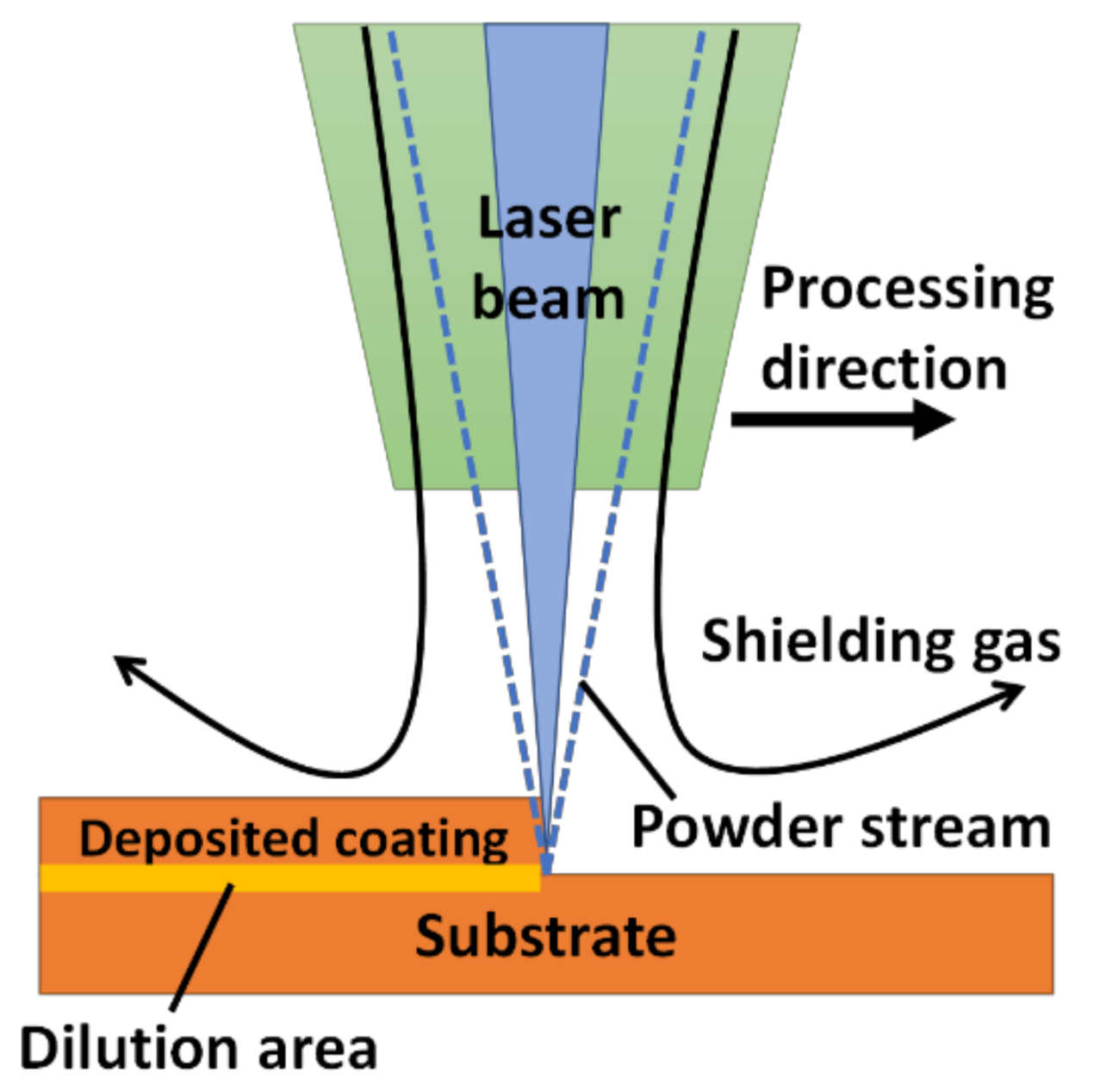
1.3. Laser Additive Manufacturing (LAM) Process: Laser Melting Deposition (LMD)
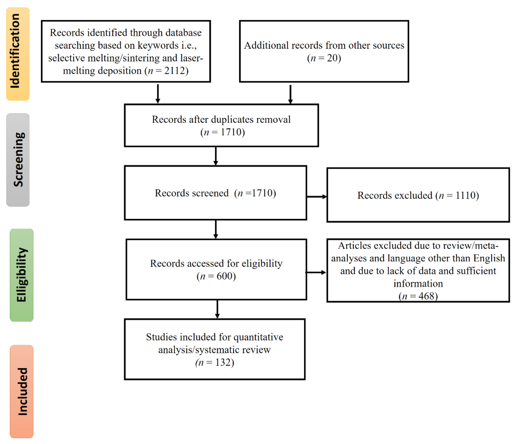
2. Methodology
3. Coatings by LMD
3.1. Ceramics-Based Coatings: Compositions and Properties
3.1.1. Alumina-Based Coatings
3.1.2. Hydroxyapatite-Based Coatings
3.1.3. Zirconia-Based Coatings
3.1.4. Silicon Carbide-Based Coatings
3.1.5. Applications of Ceramic-Based Coatings: Wear, Biomedical, and Chemical
3.2. Ceramics Reinforced Metal Matrix Composites (CMMCs)-Based Coatings: Compositions and Properties
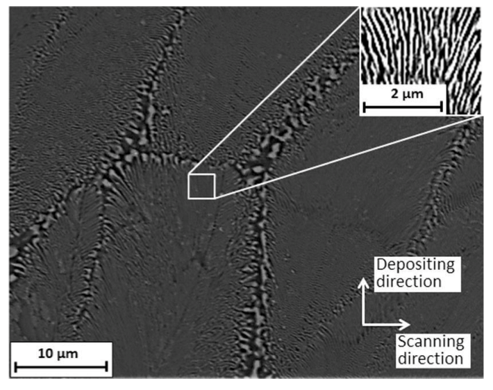
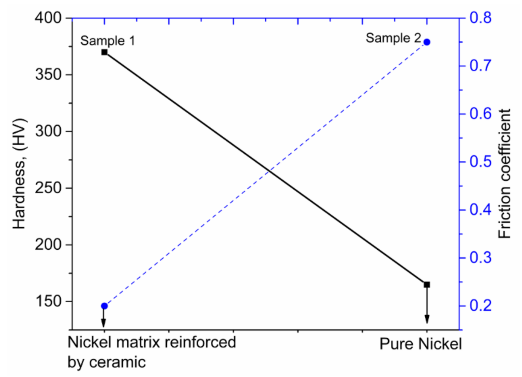
3.2.1. Nickel-Based CMMCs
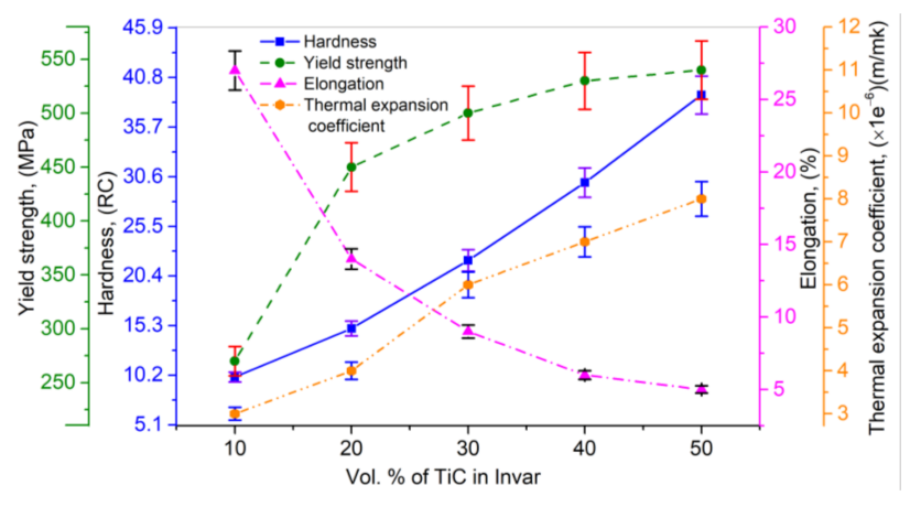
3.2.2. Inconel and Invar-Based CMMCs
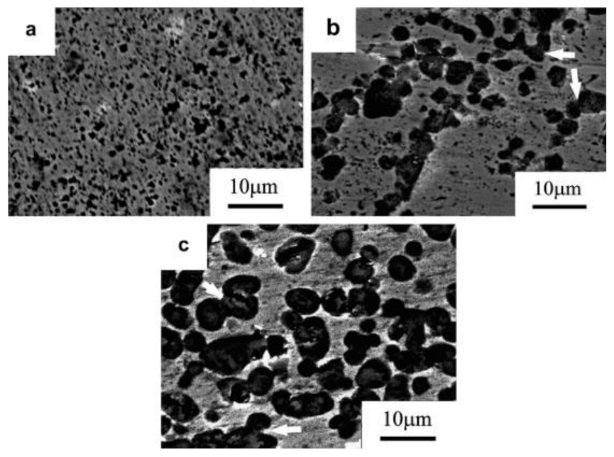
3.2.3. Titanium-Based CMMCs
3.2.4. Applications of Ceramics Reinforced Metal Matrix Composites (CMMCs)-Based Coatings: Wear, Biomedical, Chemical, and Electrochemical
4. Modelling Approaches
5. Coatings by LMD: Existing Difficulties, Solutions, and Future Trends
6. Conclusions
- Selective laser sintering (SLS), selective laser melting (SLM), and laser melting deposition (LMD) are commonly used laser additive manufacturing techniques. LMD has demonstrated capabilities to process materials with high hardness and elevated melting points due to the use of high intensity laser beams. In comparison to SLS and SLM, the LMD process presents the advantages of low work intensity and high fabrication efficiency.
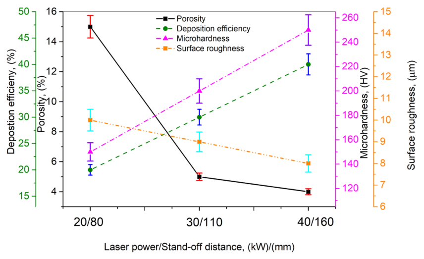
- For LMD coatings, the proper selection of process parameters results in increasing the melting degree and in the uniformization of deposited coating properties. In addition, the side effects of high thermal stress and part distortion can be reduced or even eliminated by process optimization.
- LMD demonstrated viability to process ceramics and CMMCs. The coatings growing on surfaces of bulk materials improve their characteristics and bring biological and/or chemical attributes to the materials. Fabricated samples can be utilized in aerospace, biomedical, chemical, and electrochemical industries.
- In LMD, the good adherence of the deposited ceramics or CMMCs layers to the substrate is of great importance for obtaining high quality coatings. To achieve the desired adherence strength, one should optimize correspondingly the processing parameters. Whenever the process optimization fails, a buffer layer can be introduced in between coating and substrate, possibly in combination with ultrasonic vibrations.
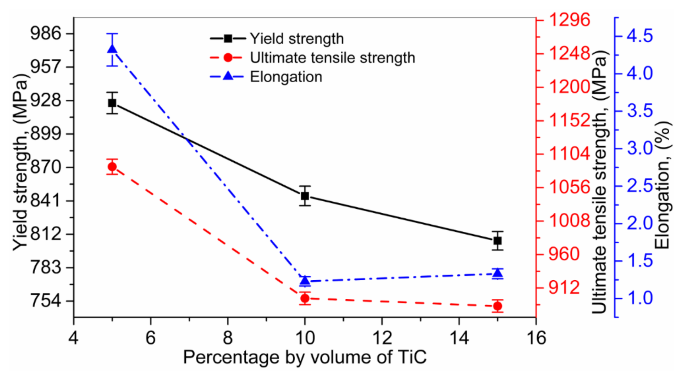
- LMD CMMCs coatings exhibit remarkable features, including high strength at elevated temperatures, improved hardness, better fatigue resistance, and creep characteristics, which makes them appropriate for advanced technological applications.Opposite behavior of the elongation had been observed, while UTS and YS showed random behaviors. The interfacial bonding between the matrix and reinforcement is therefore mandatory to obtain better UTS and YS. The weak adhesion between phases limits the load transfer from matrix to reinforcement, thus decreasing UTS and YS. Consequently, a careful selection of reinforcement and their fraction (wt.%) in combination with the metal matrix is necessary to achieve optimum physical, thermal, and mechanical properties.
- In LMD, cracks are usually initiated by the large thermal gradient, resulting in coatings with weak mechanical properties and a short life span. Their number and size can be reduced by process optimization, pre-/post-heating of the substrate, additive materials, and/or the LMD integration with ultrasonic vibrations.
- In the case of CMMCs, LMD coating meets with major difficulties due to lowered toughness and ductility. These issues can be solved by tailoring suitable microstructures within the deposited coating.
- Any kind of post-processing would require special tools and high energy, thus increasing the fabrication cost, which limits the availability of CMMCs to niche applications. One should therefore identify the best balance between appropriate thermo-mechanical properties and low production cost in order to effectively promote the MMCs.
- New materials with improved properties could be fabricated by the optimum addition of matrix and reinforcement in powder form. Moreover, coatings with complex architecture such as multilayered structures or gradient composition can be easily obtained via in situ CMMCs. One should also explore the manufacturing of the precise composition of CMMCs using different laser sources by properly modifying the microstructure and mechanical, thermal, and electrical properties.
- LMD is expected to allow for sub-mm resolution and hence for an increased accuracy of the MMCs printed via LMD.
- The latest technique is to utilize an enhanced topology design. The coatings dimensions, restrictions, and the acting forces are specified in this case by the CAD/CAM user. The software calculates based upon the maximum resistance to stress and the most appropriate shape, in accordance with user requirements. The resulting shape is, however, in most cases unconventional and convoluted. 3D printing proved suitable to fabricate such coatings. LMD can further push forward the field by using CMMCs.
Author Contributions
Funding
Institutional Review Board Statement
Informed Consent Statement
Acknowledgments
Conflicts of Interest
References
- Niu, F.; Wu, D.; Ma, G.; Wang, J.; Guo, M.; Zhang, B. Nanosized microstructure of Al2O3-ZrO2 (Y2O3) eutectics fabricated by laser engineered net shaping. Scr. Mater. 2015, 95, 39–41. [Google Scholar] [CrossRef]
- Hu, Y.; Ning, F.; Cong, W.; Li, Y.; Wang, X.; Wang, H. Ultrasonic vibration-assisted laser engineering net shaping of ZrO2-Al2O3 bulk parts: Effects on crack suppression, microstructure, and mechanical properties. Ceram. Int. 2018, 44, 2752–2760. [Google Scholar] [CrossRef]
- Hu, Y.; Cong, W.; Wang, X.; Li, Y.; Ning, F.; Wang, H. Laser deposition-additive manufacturing of TiB-Ti composites with novel three-dimensional quasi-continuous network microstructure: Effects on strengthening and toughening. Compos. Part B Eng. 2018, 133, 91–100. [Google Scholar] [CrossRef]
- Wang, H.M.; Wang, C.M.; Cai, L.X. Wear and corrosion resistance of laser clad Ni2Si/NiSi composite coatings. Surf. Coatings Technol. 2003, 168, 202–208. [Google Scholar] [CrossRef]
- Tucker, T.R.; Clauer, A.H.; Wright, I.G.; Stropki, J.T. Laser-processed composite metal cladding for slurry erosion resistance. Thin Solid Films 1984, 118, 73–84. [Google Scholar] [CrossRef]
- Man, H.C.; Zhang, S.; Cheng, F.T.; Guo, X. In situ formation of a TiN/Ti metal matrix composite gradient coating on NiTi by laser cladding and nitriding. Surf. Coatings Technol. 2006, 200, 4961–4966. [Google Scholar] [CrossRef]
- Höland, W.; Schweiger, M.; Watzke, R.; Peschke, A.; Kappert, H. Ceramics as biomaterials for dental restoration. Expert Rev. Med. Devices 2008, 5, 729–745. [Google Scholar] [CrossRef] [PubMed]
- Nevelos, J.E.; Ingham, E.; Doyle, C.; Nevelos, A.B.; Fisher, J. The influence of acetabular cup angle on the wear of “BIOLOX Forte” alumina ceramic bearing couples in a hip joint simulator. J. Mater. Sci. Mater. Med. 2001, 12, 141–144. [Google Scholar] [CrossRef] [PubMed]
- Miracle, D.B. Metal matrix composites—From science to technological significance. Compos. Sci. Technol. 2005, 65, 2526–2540. [Google Scholar] [CrossRef]
- Kurtz, A.D.; Mallon, J., Jr.; Nunn, T.A. Transducer structures employing ceramic substrates and diaphragms. U.S. Patent US4481497A, 6 11 1984. [Google Scholar]
- He, X.; Zhang, A.Y.Z.; Mansell, A.J.P.; Su, A.B. Zirconia toughened alumina ceramic foams for potential bone graft applications: Fabrication, bioactivation, and cellular responses. J. Mater. Sci. Mater. Med. 2008, 19, 2743–2749. [Google Scholar] [CrossRef]
- Mandal, N.; Doloi, B.; Mondal, B. Predictive modeling of surface roughness in high speed machining of AISI 4340 steel using yttria stabilized zirconia toughened alumina turning insert. Int. J. Refract. Met. Hard Mater. 2013, 38, 40–46. [Google Scholar] [CrossRef]
- Oane, M.; Mahmood, M.A.; Popescu, A.C.; Banica, A.; Ristoscu, C.; Mihailescu, I.N. Thermal nonlinear klein-gordon equation for nano-micro-sized metallic particle-attosecond laser pulse interaction. Materials 2021, 14, 857. [Google Scholar] [CrossRef]
- Bansal, N.P.; Boccaccini, A.R. Ceramics and Composites Processing Methods; John Wiley & Sons: Hoboken, NJ, USA, 2012; ISBN 9781118176658. [Google Scholar]
- Zhang, B.; Zheng, X.L.; Tokura, H.; Yoshikawa, M. Grinding induced damage in ceramics. J. Mater. Process. Technol. 2003, 132, 353–364. [Google Scholar] [CrossRef]
- Rosso, M. Ceramic and metal matrix composites: Routes and properties. J. Mater. Process. Technol. 2006, 175, 364–375. [Google Scholar] [CrossRef]
- Zeng, W.M.; Li, Z.C.; Pei, Z.J.; Treadwell, C. Experimental observation of tool wear in rotary ultrasonic machining of advanced ceramics. Int. J. Mach. Tools Manuf. 2005, 45, 1468–1473. [Google Scholar] [CrossRef]
- Mahmood, M.A.; Popescu, A.C.; Mihailescu, I.N. Metal Matrix Composites Synthesized by Laser-Melting Deposition: A Review. Materials 2020, 13, 2593. [Google Scholar] [CrossRef]
- ASTM F2792 − 12a. Stand. Terminol. Addit. Manuf. Technol. 2013, 10.04. [CrossRef]
- Ning, F.; Cong, W.; Hu, Y.; Wang, H. Additive manufacturing of carbon fiber-reinforced plastic composites using fused deposition modeling: Effects of process parameters on tensile properties. J. Compos. Mater. 2017, 51, 451–462. [Google Scholar] [CrossRef]
- Huang, S.H.; Liu, P.; Mokasdar, A.; Hou, L. Additive manufacturing and its societal impact: A literature review. Int. J. Adv. Manuf. Technol. 2013, 67, 1191–1203. [Google Scholar] [CrossRef]
- Prokhorov, A.M. Laser Heating of Metals; CRC Press: Boca Raton, FL, USA, 2018. [Google Scholar]
- Bandyopadhyay, A.; Panda, R.K.; McNulty, T.F.; Mohammadi, F.; Danforth, S.C.; Safari, A. Piezoelectric ceramics and composites via rapid prototyping techniques. Rapid Prototyp. J. 1998, 4, 37–49. [Google Scholar] [CrossRef]
- Bandyopadhyay, A.; Atisivan, R.; Kuhn, G.; Yeruva, S. Mechanical properties of interconnected phase alumina-Al composites. In Proceedings of the International Solid Freeform Fabrication Symposium, Austin, TX, USA, 7–9 August 2000; pp. 24–31. [Google Scholar]
- Chartier, T.; Chaput, C.; Doreau, F.; Loiseau, M. Stereolithography of structural complex ceramic parts. J. Mater. Sci. 2002, 37, 3141–3147. [Google Scholar] [CrossRef]
- Corcione, C.E.; Greco, A.; Montagna, F.; Licciulli, A.; Maffezzoli, A. Silica moulds built by stereolithography. J. Mater. Sci. 2005, 40, 4899–4904. [Google Scholar] [CrossRef]
- Waetjen, A.M.; Polsakiewicz, D.A.; Kuhl, I.; Telle, R.; Fischer, H. Slurry deposition by airbrush for selective laser sintering of ceramic components. J. Eur. Ceram. Soc. 2009, 29, 1–6. [Google Scholar] [CrossRef]
- Scheithauer, U.; Bergner, A.; Schwarzer, E.; Richter, H.J.; Moritz, T. Studies on thermoplastic 3D printing of steel-zirconia composites. J. Mater. Res. 2014, 29, 1931–1940. [Google Scholar] [CrossRef]
- Klosterman, D.A.; Chartoff, R.P.; Osborne, N.R.; Graves, G.A.; Lightman, A.; Han, G.; Bezeredi, A.; Rodrigues, S. Development of a curved layer LOM process for monolithic ceramics and ceramic matrix composites. Rapid Prototyp. J. 1999, 5, 61–71. [Google Scholar] [CrossRef]
- Bertrand, P.; Bayle, F.; Combe, C.; Goeuriot, P.; Smurov, I. Ceramic components manufacturing by selective laser sintering. Appl. Surf. Sci. 2007, 254, 989–992. [Google Scholar] [CrossRef]
- Ghosh, S.K.; Saha, P. Crack and wear behavior of SiC particulate reinforced aluminium based metal matrix composite fabricated by direct metal laser sintering process. Mater. Des. 2011, 32, 139–145. [Google Scholar] [CrossRef]
- Attar, H.; Bönisch, M.; Calin, M.; Zhang, L.C.; Scudino, S.; Eckert, J. Selective laser melting of in situ titanium-titanium boride composites: Processing, microstructure and mechanical properties. Acta Mater. 2014, 76, 13–22. [Google Scholar] [CrossRef]
- Wilkes, J.; Hagedorn, Y.C.; Meiners, W.; Wissenbach, K. Additive manufacturing of ZrO2-Al2O3 ceramic components by selective laser melting. Rapid Prototyp. J. 2013, 19, 51–57. [Google Scholar] [CrossRef]
- Borkar, T.; Gopagoni, S.; Nag, S.; Hwang, J.Y.; Collins, P.C.; Banerjee, R. In situ nitridation of titanium-molybdenum alloys during laser deposition. J. Mater. Sci. 2012, 47, 7157–7166. [Google Scholar] [CrossRef]
- Balla, V.K.; Bose, S.; Bandyopadhyay, A. Processing of bulk alumina ceramics using laser engineered net shaping. Int. J. Appl. Ceram. Technol. 2008, 5, 234–242. [Google Scholar] [CrossRef]
- Li, Y.; Hu, Y.; Cong, W.; Zhi, L.; Guo, Z. Additive manufacturing of alumina using laser engineered net shaping: Effects of deposition variables. Ceram. Int. 2017, 43, 7768–7775. [Google Scholar] [CrossRef]
- Hu, Y.; Ning, F.; Wang, H.; Cong, W.; Zhao, B. Laser engineered net shaping of quasi-continuous network microstructural TiB reinforced titanium matrix bulk composites: Microstructure and wear performance. Opt. Laser Technol. 2018, 99, 174–183. [Google Scholar] [CrossRef]
- Lee, H.; Lim, C.H.J.; Low, M.J.; Tham, N.; Murukeshan, V.M.; Kim, Y.J. Lasers in additive manufacturing: A review. Int. J. Precis. Eng. Manuf. - Green Technol. 2017, 4, 307–322. [Google Scholar] [CrossRef]
- Kruth, J.P.; Levy, G.; Klocke, F.; Childs, T.H.C. Consolidation phenomena in laser and powder-bed based layered manufacturing. CIRP Ann. - Manuf. Technol. 2007, 56, 730–759. [Google Scholar] [CrossRef]
- Hu, Y.; Li, J. Selective laser alloying of elemental titanium and boron powder: Thermal models and experiment verification. J. Mater. Process. Technol. 2017, 249, 426–432. [Google Scholar] [CrossRef]
- Balla, V.K.; Bandyopadhyay, P.P.; Bose, S.; Bandyopadhyay, A. Compositionally graded yttria-stabilized zirconia coating on stainless steel using laser engineered net shaping (LENSTM). Scr. Mater. 2007, 57, 861–864. [Google Scholar] [CrossRef]
- Hu, Y.; Wang, H.; Ning, F.; Cong, W. Laser Engineered net Shaping of Commercially Pure Titanium: Effects of Fabricating Variables; ASME International: New York, NY, USA, 2016. [Google Scholar]
- Gu, D.D.; Meiners, W.; Wissenbach, K.; Poprawe, R. Laser additive manufacturing of metallic components: Materials, processes and mechanisms. Int. Mater. Rev. 2012, 57, 133–164. [Google Scholar] [CrossRef]
- Weng, F.; Chen, C.; Yu, H. Research status of laser cladding on titanium and its alloys: A review. Mater. Des. 2014, 58, 412–425. [Google Scholar] [CrossRef]
- Wu, Q.; Li, W.; Zhong, N.; Gang, W.; Haishan, W. Microstructure and wear behavior of laser cladding VC-Cr7C3 ceramic coating on steel substrate. Mater. Des. 2013, 49, 10–18. [Google Scholar] [CrossRef]
- Emamian, A.; Corbin, S.F.; Khajepour, A. Effect of laser cladding process parameters on clad quality and in-situ formed microstructure of Fe-TiC composite coatings. Surf. Coatings Technol. 2010, 205, 2007–2015. [Google Scholar] [CrossRef]
- Gao, Y.L.; Wang, C.S.; Yao, M.; Liu, H. bin The resistance to wear and corrosion of laser-cladding Al2O3 ceramic coating on Mg alloy. Appl. Surf. Sci. 2007, 253, 5306–5311. [Google Scholar] [CrossRef]
- Weidong, Z.; Qibin, L.; Min, Z.; Xudong, W. Biocompatibility of a functionally graded bioceramic coating made by wide-band laser cladding. J. Biomed. Mater. Res. Part A 2008, 87A, 429–433. [Google Scholar] [CrossRef]
- Wu, D.; Guo, M.; Ma, G.; Niu, F. Dilution characteristics of ultrasonic assisted laser clad yttria-stabilized zirconia coating. Mater. Lett. 2015, 141, 207–209. [Google Scholar] [CrossRef]
- Alumina Chemical Compound Britannica. Available online: https://www.britannica.com/science/alumina (accessed on 22 July 2020).
- Balakrishnan, P.; Thomas, S. Inert ceramics. In Fundamental Biomaterials: Ceramics; Elsevier Inc.: Amsterdam, The Netherlands, 2018; pp. 117–127. ISBN 9780081022047. [Google Scholar]
- Wu, D.; Sun, B.; Niu, F.; Ma, G.; Zhang, Y.; Jin, Z. Microstructure and crack in color Al2O3 samples by laser engineered net shaping. Kuei Suan Jen Hsueh Pao J. Chin. Ceram. Soc. 2013, 41, 1621–1626. [Google Scholar] [CrossRef]
- Niu, F.; Wu, D.; Zhou, S.; Ma, G. Power prediction for laser engineered net shaping of Al2O3 ceramic parts. J. Eur. Ceram. Soc. 2014, 34, 3811–3817. [Google Scholar] [CrossRef]
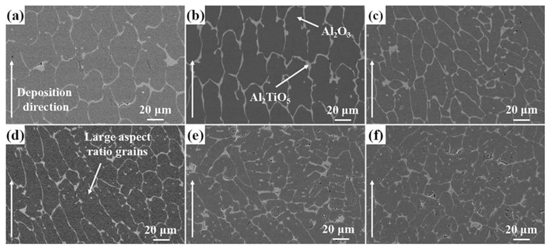
- Huang, Y.; Wu, D.; Zhao, D.; Niu, F.; Zhang, H.; Yan, S.; Ma, G. Process optimization of melt growth alumina/aluminum titanate composites directed energy deposition: Effects of scanning speed. Addit. Manuf. 2020, 35, 101210. [Google Scholar] [CrossRef]
- Dorozhkin, S. Calcium Orthophosphate Cements and Concretes. Materials 2009, 2, 221–291. [Google Scholar] [CrossRef] [Green Version]
- Xia, L.; Lin, K.; Jiang, X.; Xu, Y.; Zhang, M.; Chang, J.; Zhang, Z. Enhanced osteogenesis through nano-structured surface design of macroporous hydroxyapatite bioceramic scaffolds via activation of ERK and p38 MAPK signaling pathways. J. Mater. Chem. B 2013, 1, 5403–5416. [Google Scholar] [CrossRef] [PubMed]
- Tabrizian, M. Expression of concern: Nanodimensional and Nanocrystalline apatites and other calcium orthophosphates in biomedical engineering, biology and medicine. Materials 2009, 2, 1975–2045. Materials 2016, 9, 752. [Google Scholar] [CrossRef] [Green Version]
- Vallet-Regí, M.; González-Calbet, J.M. Calcium phosphates as substitution of bone tissues. Prog. Solid State Chem. 2004, 32, 1–31. [Google Scholar] [CrossRef]
- Okabayashi, R.; Nakamura, M.; Okabayashi, T.; Tanaka, Y.; Nagai, A.; Yamashita, K. Efficacy of polarized hydroxyapatite and silk fibroin composite dressing gel on epidermal recovery from full-thickness skin wounds. J. Biomed. Mater. Res. Part B Appl. Biomater. 2009, 90B, 641–646. [Google Scholar] [CrossRef] [PubMed]
- Shin, Y.; Aoki, H.; Yoshiyama, N.; Akao, M.; Higashikata, M. Surface properties of hydroxyapatite ceramic as new percutaneous material in skin tissue. J. Mater. Sci. Mater. Med. 1992, 3, 219–221. [Google Scholar] [CrossRef]
- Ji, D.Y.; Kuo, T.F.; Wu, H.D.; Yang, J.C.; Lee, S.Y. A novel injectable chitosan/polyglutamate polyelectrolyte complex hydrogel with hydroxyapatite for soft-tissue augmentation. Carbohydr. Polym. 2012, 89, 1123–1130. [Google Scholar] [CrossRef]
- Liu, M.; Zhou, G.; Song, W.; Li, P.; Liu, H.; Niu, X.; Fan, Y. Effect of nano-hydroxyapatite on the axonal guidance growth of rat cortical neurons. Nanoscale 2012, 4, 3201–3207. [Google Scholar] [CrossRef]
- Uskoković, V.; Uskoković, D.P. Nanosized hydroxyapatite and other calcium phosphates: Chemistry of formation and application as drug and gene delivery agents. J. Biomed. Mater. Res. Part B Appl. Biomater. 2011, 96 B, 152–191. [Google Scholar] [CrossRef] [Green Version]
- Rodríguez-Ruiz, I.; Delgado-López, J.M.; Durán-Olivencia, M.A.; Iafisco, M.; Tampieri, A.; Colangelo, D.; Prat, M.; Gómez-Morales, J. PH-responsive delivery of doxorubicin from citrate-apatite nanocrystals with tailored carbonate content. Langmuir 2013, 29, 8213–8221. [Google Scholar] [CrossRef]
- Lin, K.; Liu, P.; Wei, L.; Zou, Z.; Zhang, W.; Qian, Y.; Shen, Y.; Chang, J. Strontium substituted hydroxyapatite porous microspheres: Surfactant-free hydrothermal synthesis, enhanced biological response and sustained drug release. Chem. Eng. J. 2013, 222, 49–59. [Google Scholar] [CrossRef]
- Lin, K.; Chen, L.; Liu, P.; Zou, Z.; Zhang, M.; Shen, Y.; Qiao, Y.; Liu, X.; Chang, J. Hollow magnetic hydroxyapatite microspheres with hierarchically mesoporous microstructure for pH-responsive drug delivery. CrystEngComm 2013, 15, 2999–3008. [Google Scholar] [CrossRef]
- Zhu, S.H.; Huang, B.Y.; Zhou, K.C.; Huang, S.P.; Liu, F.; Li, Y.M.; Xue, Z.G.; Long, Z.G. Hydroxyapatite nanoparticles as a novel gene carrier. J. Nanoparticle Res. 2004, 6, 307–311. [Google Scholar] [CrossRef]
- Li, J.; Chen, Y.C.; Tseng, Y.C.; Mozumdar, S.; Huang, L. Biodegradable calcium phosphate nanoparticle with lipid coating for systemic siRNA delivery. J. Control. Release 2010, 142, 416–421. [Google Scholar] [CrossRef] [Green Version]
- Hilbrig, F.; Freitag, R. Isolation and purification of recombinant proteins, antibodies and plasmid DNA with hydroxyapatite chromatography. Biotechnol. J. 2012, 7, 90–102. [Google Scholar] [CrossRef]
- Morrison, C.J.; Gagnon, P.; Cramer, S.M. Purification of monomeric mAb from associated aggregates using selective desorption chromatography in hydroxyapatite systems. Biotechnol. Bioeng. 2011, 108, 813–821. [Google Scholar] [CrossRef]
- Kozlova, D.; Chernousova, S.; Knuschke, T.; Buer, J.; Westendorf, A.M.; Epple, M. Cell targeting by antibody-functionalized calcium phosphate nanoparticles. J. Mater. Chem. 2012, 22, 396–404. [Google Scholar] [CrossRef]
- Chen, F.; Huang, P.; Zhu, Y.J.; Wu, J.; Cui, D.X. Multifunctional Eu3+/Gd3+ dual-doped calcium phosphate vesicle-like nanospheres for sustained drug release and imaging. Biomaterials 2012, 33, 6447–6455. [Google Scholar] [CrossRef]
- Epple, M.; Ganesan, K.; Heumann, R.; Klesing, J.; Kovtun, A.; Neumann, S.; Sokolova, V. Application of calcium phosphate nanoparticles in biomedicine. J. Mater. Chem. 2010, 20, 18–23. [Google Scholar] [CrossRef]
- Tlotleng, M.; Akinlabi, E.; Shukla, M.; Pityana, S. Microstructures, hardness and bioactivity of hydroxyapatite coatings deposited by direct laser melting process. Mater. Sci. Eng. C 2014, 43, 189–198. [Google Scholar] [CrossRef]
- Du, H.; Huo, W.; Gao, H.; Wang, L.; Qiu, S.; Liu, J. Influence of Zirconia on Hydroxyapatite Coating on Ti-Alloy by Laser Cladding. J. Tianjin Univ. English Ed. 2003, 9, 292–295. [Google Scholar]
- Zeng, H.; Lacefield, W.R. The study of surface transformation of pulsed laser deposited hydroxyapatite coatings. J. Biomed. Mater. Res. 2000, 50, 239–247. [Google Scholar] [CrossRef]
- Hasan, M.F.; Wang, J.; Berndt, C.C. Effect of power and stand-off distance on plasma sprayed hydroxyapatite coatings. Mater. Manuf. Process. 2013, 28, 1279–1285. [Google Scholar] [CrossRef]
- Farid, S.B.H. Structure, microstructure, and properties of bioceramics. In Bioceramics: For Materials Science and Engineering; Elsevier: Amsterdam, The Netherlands, 2019; pp. 39–76. [Google Scholar]
- Gutknecht, D.; Chevalier, J.; Garnier, V.; Fantozzi, G. Key role of processing to avoid low temperature ageing in alumina zirconia composites for orthopaedic application. J. Eur. Ceram. Soc. 2007, 27, 1547–1552. [Google Scholar] [CrossRef]
- Ganesh, I.; Olhero, S.M.; Torres, P.M.C.; Alves, F.J.; Ferreira, J.M.F. Hydrolysis-induced aqueous gelcasting for near-net shape forming of ZTA ceramic composites. J. Eur. Ceram. Soc. 2009, 29, 1393–1401. [Google Scholar] [CrossRef]
- Wang, J.; Stevens, R. Zirconia-toughened alumina (ZTA) ceramics. J. Mater. Sci. 1989, 24, 3421–3440. [Google Scholar] [CrossRef]
- Denry, I.; Kelly, J.R. State of the art of zirconia for dental applications. Dent. Mater. 2008, 24, 299–307. [Google Scholar] [CrossRef]
- Yan, S.; Wu, D.; Niu, F.; Ma, G.; Kang, R. Al2O3-ZrO2 eutectic ceramic via ultrasonic-assisted laser engineered net shaping. Ceram. Int. 2017, 43, 15905–15910. [Google Scholar] [CrossRef]
- Hu, Y.; Wang, H.; Cong, W.; Zhao, B. Directed energy deposition of zirconia-toughened alumina ceramic: Novel microstructure formation and mechanical performance. J. Manuf. Sci. Eng. 2020, 142. [Google Scholar] [CrossRef]
- Harris, G.L. PROPERTIES OF Silicon Carbide; INSPEC, The Institution of Electrical Engineers: London, UK, 1995; ISBN 0852968701. [Google Scholar]
- Ji, R.; Liu, Y.; Zhang, Y.; Cai, B.; Li, X.; Zheng, C. Effect of machining parameters on surface integrity of silicon carbide ceramic using end electric discharge milling and mechanical grinding hybrid machining. J. Mech. Sci. Technol. 2013, 27, 177–183. [Google Scholar] [CrossRef]
- Adebiyi, I.; Fatoba, O.; Pityana, S.; Popoola, P. Parameters Optimization, Microstructure and Micro-Hardness of Silicon Carbide Laser Deposited on Titanium Alloy. In Proceedings of the International Conference on Surface Modification Technologies, Milan, Italy, 29 June–1 July 2016. [Google Scholar]
- Dutta Majumdar, J.; Ramesh Chandra, B.; Nath, A.K.; Manna, I. Studies on compositionally graded silicon carbide dispersed composite surface on mild steel developed by laser surface cladding. J. Mater. Process. Technol. 2008, 203, 505–512. [Google Scholar] [CrossRef]
- Lusquiños, F.; Pou, J.; Quintero, F.; Pérez-Amor, M. Laser cladding of SiC/Si composite coating on Si-SiC ceramic substrates. Surf. Coatings Technol. 2008, 202, 1588–1593. [Google Scholar] [CrossRef]
- Wang, H.M.; Yu, Y.L.; Li, S.Q. Microstructure and tribological properties of laser clad CaF2/Al2O3 self-lubrication wear-resistant ceramic matrix composite coatings. Scr. Mater. 2002, 47, 57–61. [Google Scholar] [CrossRef]
- Xu, X.; Han, J.; Wang, C.; Huang, A. Laser cladding of composite bioceramic coatings on titanium alloy. J. Mater. Eng. Perform. 2016, 25, 656–667. [Google Scholar] [CrossRef]
- Roy, M.; Vamsi Krishna, B.; Bandyopadhyay, A.; Bose, S. Laser processing of bioactive tricalcium phosphate coating on titanium for load-bearing implants. Acta Biomater. 2008, 4, 324–333. [Google Scholar] [CrossRef] [PubMed]
- Khanna, A.S.; Kumari, S.; Kanungo, S.; Gasser, A. Hard coatings based on thermal spray and laser cladding. Int. J. Refract. Met. Hard Mater. 2009, 27, 485–491. [Google Scholar] [CrossRef]
- Kumar, B.K.A.G.; Ananthaprasad, M.; GopalaKrishna, K. A review on mechanical and tribological behaviors of nickel matrix composites. Indian J. Sci. Technol. 2016, 9, 1–7. [Google Scholar] [CrossRef]
- Gopagoni, S.; Hwang, J.Y.; Singh, A.R.P.; Mensah, B.A.; Bunce, N.; Tiley, J.; Scharf, T.W.; Banerjee, R. Microstructural evolution in laser deposited nickel-titanium-carbon in situ metal matrix composites. J. Alloys Compd. 2011, 509, 1255–1260. [Google Scholar] [CrossRef]
- Li, Y.; Bai, P.; Wang, Y.; Hu, J.; Guo, Z. Effect of TiC content on Ni/TiC composites by direct laser fabrication. Mater. Des. 2009, 30, 1409–1412. [Google Scholar] [CrossRef]
- Hong, C.; Gu, D.; Dai, D.; Alkhayat, M.; Urban, W.; Yuan, P.; Cao, S.; Gasser, A.; Weisheit, A.; Kelbassa, I.; et al. Laser additive manufacturing of ultrafine TiC particle reinforced Inconel 625 based composite parts: Tailored microstructures and enhanced performance. Mater. Sci. Eng. A 2015, 635, 118–128. [Google Scholar] [CrossRef]
- Li, X.C.; Stampfl, J.; Prinz, F.B. Mechanical and thermal expansion behavior of laser deposited metal matrix composites of Invar and TiC. Mater. Sci. Eng. A 2000, 282, 86–90. [Google Scholar] [CrossRef]
- Liu, D.; Zhang, S.Q.; Li, A.; Wang, H.M. Microstructure and tensile properties of laser melting deposited TiC/TA15 titanium matrix composites. J. Alloys Compd. 2009, 485, 156–162. [Google Scholar] [CrossRef]
- Mahamood, R.M.; Akinlabi, E.T.; Shukla, M.; Pityana, S. Scanning velocity influence on microstructure, microhardness and wear resistance performance of laser deposited Ti6Al4V/TiC composite. Mater. Des. 2013, 50, 656–666. [Google Scholar] [CrossRef]
- Tamirisakandala, S.; Miracle, D.B.; Srinivasan, R.; Gunasekera, J.S. Titanium Alloyed with Boron. Adv. Mater. Process. 2006, 164, 41. [Google Scholar]
- Ochonogor, O.F.; Meacock, C.; Pityana, S.L.; PopoolaI, P.A.I.; Majumder, J.D. Microstructure characterization of laser-deposited titanium carbide and zirconium-based titanium metal matrix composites. J. South. African Inst. Min. Metall. 2012, 112, 905–910. [Google Scholar]
- Das, M.; Balla, V.K.; Basu, D.; Manna, I.; Sampath Kumar, T.S.; Bandyopadhyay, A. Laser processing of in situ synthesized TiB-TiN-reinforced Ti6Al4V alloy coatings. Scr. Mater. 2012, 66, 578–581. [Google Scholar] [CrossRef]
- Van Acker, K.; Vanhoyweghen, D.; Persoons, R.; Vangrunderbeek, J. Influence of tungsten carbide particle size and distribution on the wear resistance of laser clad WC/Ni coatings. In Proceedings of the Wear; Elsevier: Amsterdam, The Netherlands, 2005; Volume 258, pp. 194–202. [Google Scholar]
- Das, M.; Balla, V.K.; Kumar, T.S.S.; Manna, I. Fabrication of Biomedical Implants using Laser Engineered Net Shaping (LENSTM). Trans. Indian Ceram. Soc. 2013, 72, 169–174. [Google Scholar] [CrossRef]
- Balla, V.K.; Bhat, A.; Bose, S.; Bandyopadhyay, A. Laser processed TiN reinforced Ti6Al4V composite coatings. J. Mech. Behav. Biomed. Mater. 2012, 6, 9–20. [Google Scholar] [CrossRef] [PubMed] [Green Version]
- Das, M.; Balla, V.K.; Kumar, T.S.S.; Bandyopadhyay, A.; Manna, I. Tribological, electrochemical and in vitro biocompatibility properties of SiC reinforced composite coatings. Mater. Des. 2016, 95, 510–517. [Google Scholar] [CrossRef]
- Acharya, R.; Sharon, J.A.; Staroselsky, A. Prediction of microstructure in laser powder bed fusion process. Acta Mater. 2017, 124, 360–371. [Google Scholar] [CrossRef]
- Fergani, O.; Berto, F.; Welo, T.; Liang, S.Y. Analytical modelling of residual stress in additive manufacturing. Fatigue Fract. Eng. Mater. Struct. 2017, 40, 971–978. [Google Scholar] [CrossRef]
- Chen, Q.; Guillemot, G.; Gandin, C.A.; Bellet, M. Three-dimensional finite element thermomechanical modeling of additive manufacturing by selective laser melting for ceramic materials. Addit. Manuf. 2017, 16, 124–137. [Google Scholar] [CrossRef] [Green Version]
- Yu, T.; Li, M.; Breaux, A.; Atri, M.; Obeidat, S.; Ma, C. Experimental and numerical study on residual stress and geometric distortion in powder bed fusion process. J. Manuf. Process. 2019, 46, 214–224. [Google Scholar] [CrossRef]
- Mahmood, M.A.; Popescu, A.C.; Hapenciuc, C.L.; Ristoscu, C.; Visan, A.I.; Oane, M.; Mihailescu, I.N. Estimation of clad geometry and corresponding residual stress distribution in laser melting deposition: Analytical modeling and experimental correlations. Int. J. Adv. Manuf. Technol. 2020, 111, 77–91. [Google Scholar] [CrossRef]
- Mahmood, M.A.; Popescu, A.C.; Oane, M.; Ristoscu, C.; Chioibasu, D.; Mihai, S.; Mihailescu, I.N. Three-jet powder flow and laser–powder interaction in laser melting deposition: Modelling versus experimental correlations. Metals 2020, 10, 1113. [Google Scholar] [CrossRef]
- Arif, M.; Popescu, A.C.; Oane, M.; Chioibasu, D.; Popescu-pelin, G.; Ristoscu, C.; Mihailescu, I.N. Grain refinement and mechanical properties for AISI304 stainless steel single-tracks by laser melting deposition:Mathematical modelling versus experimental results. Results Phys. 2021, 22, 103880. [Google Scholar] [CrossRef]
- Buc, A.M.; Oane, M.; Mahmood, M.A.; Mih, I.N.; Popescu, A.C.; Sava, B.A.; Ristoscu, C. Non-fourier estimate of electron temperature in case of femtosecond laser pulses interaction with metals. Metals 2020, 10, 606. [Google Scholar] [CrossRef]
- Asif, U.R.; Sglavo, V.M. 3D printing of geopolymer-based concrete for building applications. Rapid prot. 2020, 26, 1783–1788. [Google Scholar] [CrossRef]
- Mahmood, M.A.; Han, C.F.; Chu, H.Y.; Sun, C.C.; Wu, W.H.; Lin, W.J.; Liu, L.C.; Lai, J.Y.; Mihailescu, I.N.; Lin, J.F. Effects of roll pattern and reduction ratio on optical characteristics of A1008 cold–rolled steel specimens: Analytical approach and experimental correlations. Int. J. Adv. Manuf. Technol. 2020, 111, 2001–2020. [Google Scholar] [CrossRef]
- Mahmood, M.A.; Tsai, T.Y.; Hwu, Y.J.; Lin, W.J.; Liu, L.C.; Lai, J.Y.; Pan, J.W.; Li, W.L.; Lin, J.F. Effect of fractal parameters on optical properties of cold rolled aluminum alloy strips with induced surface deflection: Simulations and experimental correlations. J. Mater. Process. Technol. 2020, 279, 116554. [Google Scholar] [CrossRef]
- Bucă, A.M.; Oane, M.; Mihăilescu, I.N.; Mahmood, M.A.; Sava, B.A.; Ristoscu, C. An analytical multiple-temperature model for flash laser irradiation on single-layer graphene. Nanomaterials 2020, 10, 1319. [Google Scholar] [CrossRef]
- Mahmood, M.A.; Visan, A.I.; Ristoscu, C.; Mihailescu, I.N. Artificial neural network algorithms for 3D printing. Materials 2021, 14, 163. [Google Scholar] [CrossRef] [PubMed]
- Sayyad Amin, J.; Nikooee, E.; Ayatollahi, S.; Alamdari, A. Investigating wettability alteration due to asphaltene precipitation: Imprints in surface multifractal characteristics. Appl. Surf. Sci. 2010, 256, 6466–6472. [Google Scholar] [CrossRef]
- Yang, Y.; Lan, J.; Li, X. Study on bulk aluminum matrix nano-composite fabricated by ultrasonic dispersion of nano-sized SiC particles in molten aluminum alloy. Mater. Sci. Eng. A 2004, 380, 378–383. [Google Scholar] [CrossRef]
- Ning, F.; Hu, Y.; Liu, Z.; Wang, X.; Li, Y.; Cong, W. Ultrasonic vibration-assisted laser engineered net shaping of inconel 718 Parts: Microstructural and mechanical characterization. J. Manuf. Sci. Eng. Trans. ASME 2018, 140. [Google Scholar] [CrossRef]
- Abramov, O.V. Action of high intensity ultrasound on solidifying metal. Ultrasonics 1987, 25, 73–82. [Google Scholar] [CrossRef]
- Cong, W.; Ning, F. A fundamental investigation on ultrasonic vibration-assisted laser engineered net shaping of stainless steel. Int. J. Mach. Tools Manuf. 2017, 121, 61–69. [Google Scholar] [CrossRef]
- Moraru, L. Ultrasound action on strength properties of polycrystalline metals. In The Annals of University “Dunărea De Jos “of Galaţi Fascicle VIII; Galati University Press: Galati, Romania, 2006; pp. 73–76. [Google Scholar]
- Munz, D.; Fett, T. Ceramics: Mechanical Properties, Failure Behaviour, Materials Selection Illustrate; Springer Science & Business Media: Berlin/Heidelberg, Germany, 1999; ISBN 9783540653769. [Google Scholar]
- Quazi, M.M.; Fazal, M.A.; Haseeb, A.S.M.A.; Yusof, F.; Masjuki, H.H.; Arslan, A. Effect of rare earth elements and their oxides on tribo-mechanical performance of laser claddings: A review. J. Rare Earths 2016, 34, 549–564. [Google Scholar] [CrossRef]
- Zhou, S.; Huang, Y.; Zeng, X.; Hu, Q. Microstructure characteristics of Ni-based WC composite coatings by laser induction hybrid rapid cladding. Mater. Sci. Eng. A 2008, 480, 564–572. [Google Scholar] [CrossRef]
- Triantafyllidis, D.; Li, L.; Stott, F.H. Crack-free densification of ceramics by laser surface treatment. Surf. Coatings Technol. 2006, 201, 3163–3173. [Google Scholar] [CrossRef]
- Hu, Y.; Zhao, B.; Ning, F.; Wang, H.; Cong, W. In-situ ultrafine three-dimensional quasi-continuous network microstructural TiB reinforced titanium matrix composites fabrication using laser engineered net shaping. Mater. Lett. 2017, 195, 116–119. [Google Scholar] [CrossRef]
- Huang, L.J.; Geng, L.; Peng, H.X. Microstructurally inhomogeneous composites: Is a homogeneous reinforcement distribution optimal? Prog. Mater. Sci. 2015, 71, 93–168. [Google Scholar] [CrossRef]


| Composition | Al2O3 + MgO | |
| Properties (Units) | Porosity (%) | <0.10 |
| Purity (%) | 99.9 | |
| Density (g/cm3) | 3.0–4.0 | |
| Young’s modulus (GPa) | 350–380 | |
| Bending strength (MPa) | 7500 | |
| Poisson’s ratio | 0.23 | |
| Hardness (HV 0.1) | 2100–2200 | |
| Coefficient of thermal expansion (×10−6/K) | 8.0 | |
| Formula | Ca5(PO4)3(OH) |
| Composition | Ca + P |
| Theoretical density | 3.156 (g/cm3) |
| Hardness | 500–800 (HV) |
| Tensile strength | 40–100 (MPa) |
| Bend strength | 20–80 (MPa) |
| Compressive strength | 100–900 (MPa) |
| Fracture toughness | 1.0 (MPam1/2) |
| Young’s modulus | 70–120 (GPa) |
| Properties (Units) | Zirconia |
|---|---|
| Chemical composition | ZrO2 + Y2O3 + MgO |
| Porosity (%) | <0.10 |
| Purity (%) | 95.0–97.0 |
| Density (g/cm3) | 5.0–6.0 |
| Young’s modulus (GPa) | 200–220 |
| Bending strength (MPa) | 500–1000 |
| Poisson’s ratio | 0.30 |
| Hardness (HV 0.1) | 1200–1250 |
| Coefficient of thermal expansion (×10−6/k) | 11.0 |
| Properties (Units) | Silicon Carbide |
|---|---|
| Chemical composition | SiC + FC + Fe2O3 |
| Max. service temperature (°C) | 1380 |
| Density (g/cm3) | 3.02 |
| Bending strength (MPa) | 280 (1200 °C) |
| Elastic modulus (GPa) | 300 (1200 °C) |
| Thermal conductivity (W/mk) | 45 (1200 °C) |
| Thermal expansion coefficient (×10−6/k) | 4.5 |
| Mohs hardness | 13 |
| Powder Type | Manufacturer | Particle Size | Images | References |
|---|---|---|---|---|
| Alumina | VAW aluminium AG | 3–6 (µm) | 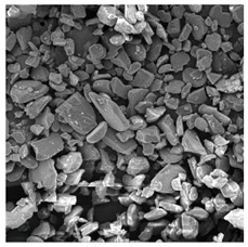 | [35] |
| Hydroxyapatite | Sigma Aldrich | 20 (nm) | 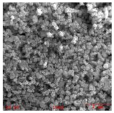 | [57] |
| Zirconia | Fanmeiya Advanced Materials | 0.16–0.60 (µm) | 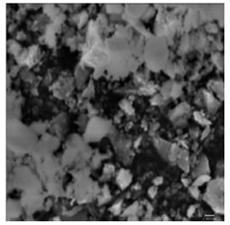 | [78] |
| Silicon carbide | Leading Manufacturer | 50–75 (µm) | 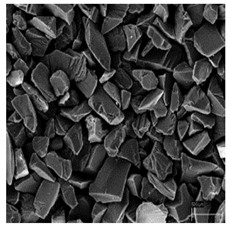 | [85] |
| Technique | Illustration | References |
|---|---|---|
| Integrating the ultrasonic technology with LMD process | With periodical positive–negative pressure, ultrasonic vibration produces two non-linear actions of acoustic streaming and transient cavitation. The absorption of acoustic oscillations in liquid materials generates a stable flow, also known as acoustic streaming. Transient cavitation assists the formation, growth, pulsation, and collapse of the micro-sized bubbles. These two non-linear actions facilitate material movement within the liquid, which is beneficial for regulating material dispersion. This in return reduces the thermal gradient, stresses, or cracks, and refines grain formation in the deposited coating. | [122,123,124,125,126] |
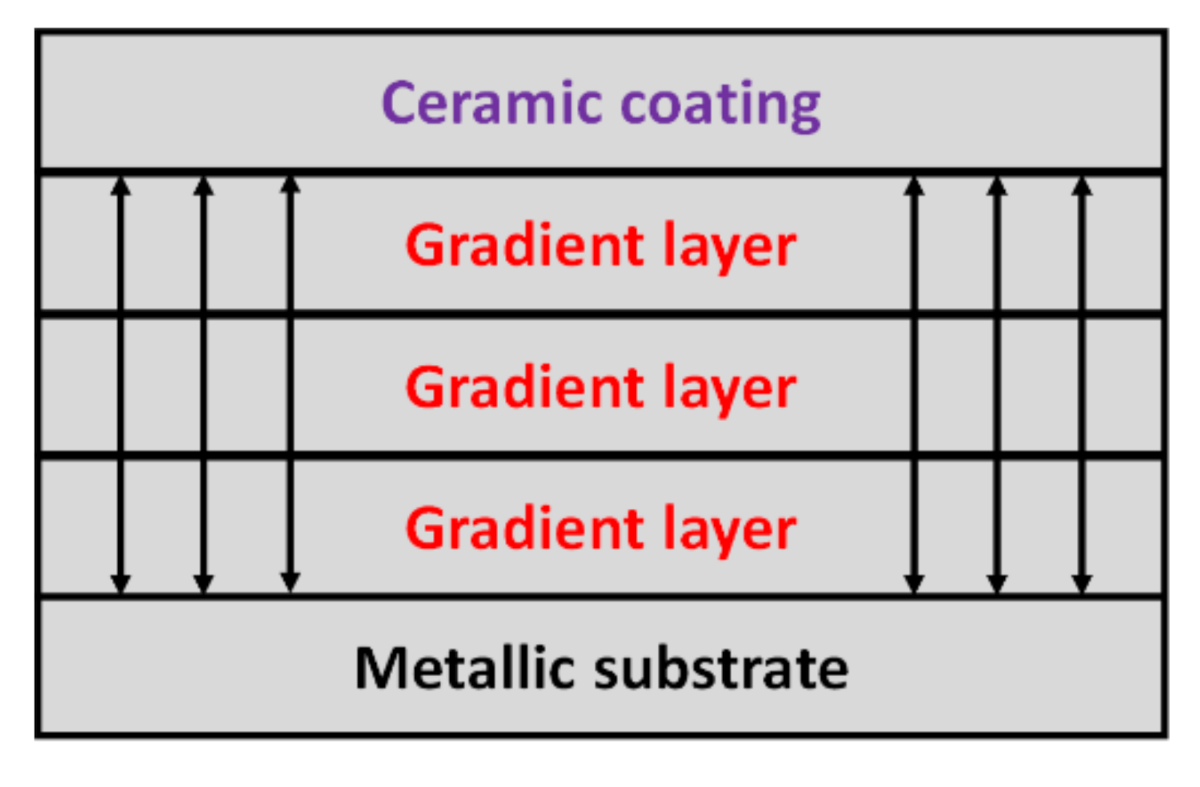
| Adding a buffer or functionally graded layer | Adding a buffer layer proved efficient for enhancing the compatibility between the deposited ceramic coatings and metallic substrate, thus rendering a firm bonding between them, as shown in Figure 16. | [47,48] |
| Technique | Illustration | References |
|---|---|---|
| Addition of rare earth oxides | Rare earth oxides can change the dynamics of melt pool and are capable of preventing crack initiation and propagation via preventing dislocation movements. | [128] |
| Pre-/post-heating of substrate | The main purpose is to decrease the thermal gradient between the deposited coating and substrate. This process has been proved to successfully suppress the cracks in the LMD process. However, such treatments are time- and cost-consuming, requiring supplementary procedures and equipment. Further, this technique may even alter the required properties of the coated material. | [105,129] |
Publisher’s Note: MDPI stays neutral with regard to jurisdictional claims in published maps and institutional affiliations. |
© 2021 by the authors. Licensee MDPI, Basel, Switzerland. This article is an open access article distributed under the terms and conditions of the Creative Commons Attribution (CC BY) license (http://creativecommons.org/licenses/by/4.0/).
Share and Cite
Mahmood, M.A.; Bănică, A.; Ristoscu, C.; Becherescu, N.; Mihăilescu, I.N. Laser Coatings via State-of-the-Art Additive Manufacturing: A Review. Coatings 2021, 11, 296. https://doi.org/10.3390/coatings11030296
Mahmood MA, Bănică A, Ristoscu C, Becherescu N, Mihăilescu IN. Laser Coatings via State-of-the-Art Additive Manufacturing: A Review. Coatings. 2021; 11(3):296. https://doi.org/10.3390/coatings11030296
Chicago/Turabian StyleMahmood, Muhammad Arif, Alexandra Bănică, Carmen Ristoscu, Nicu Becherescu, and Ion N. Mihăilescu. 2021. "Laser Coatings via State-of-the-Art Additive Manufacturing: A Review" Coatings 11, no. 3: 296. https://doi.org/10.3390/coatings11030296