Article

Prediction of Thermal Spray Coatings Performance in Marine Environments by Combination of Laboratory and Field Tests

1
School of Engineering, University of Leicester, University Road, Leicester LE1 7RH, UK
2
NSIRC, Granta Park, Cambridge CB21 6AL, UK
3
TWI, Granta Park, Cambridge CB21 6AL, UK
4
LaSIE, UMR 7356 CNRS-La Rochelle Université, Avenue Michel Crépeau, 17000 La Rochelle, France
5
Centro Tecnológico CTC, C/Isabel Torres 1, 39011 Santander, Spain
*
Author to whom correspondence should be addressed.
Coatings 2021, 11(3), 320; https://doi.org/10.3390/coatings11030320
Submission received: 24 February 2021 / Revised: 4 March 2021 / Accepted: 8 March 2021 / Published: 11 March 2021
(This article belongs to the Special Issue Coatings Challenges in Harsh Environments)

Abstract

:
Cost-effective corrosion mitigation of offshore steel structures can be achieved by thermal spray coatings. These coatings, when comprised of Al, Zn and their alloys, provide a physical barrier against the environment when intact, and cathodic protection to underlying steel when damaged. Due to the complexity of marine environments, laboratory tests should be combined with field work in order to understand the corrosion protection offered by these coatings. The work presented here was carried out with thermal spray coatings of aluminum alloys (AA1050, AA1100, Al-5Mg) and Zn-15Al prepared by Twin Wire Arc Spray onto low carbon steel substrates. The resulting coatings were ~300 μm in thickness, and 5% of surface area defects were artificially machined in order to expose the steel substrate, simulating mechanical damage or erosion of the coating. Electrochemical data collected over a 90 days period showed a good correlation between laboratory and real marine environment results. Aluminum alloys showed better corrosion protection in fully immersed conditions, while zinc alloys performed better in atmospheric and splash zones. Overall, these results aim to improve design of thermal spray coatings to protect carbon steel in marine environments.

Graphical Abstract

1. Introduction

Marine environments are highly corrosive to metals, resulting in premature failure of offshore structures, ships, pipelines and bridges. Here, carbon steel is commonly used due to its high yield strength and low cost, albeit its resistance to corrosion is less than desirable. Thermal spray (TS) coatings have been used to mitigate marine corrosion for decades [1,2,3]. Since their introduction into the market, only limited improvements have been reported. Further optimization should be developed taking into account the effect of the environment which will aid the design of safer, low-cost offshore structures with low maintenance.
Coatings are used nowadays in many different forms and with a wide range of applications, providing protection to the underlying material against physical or chemical degradation. Focusing on thermal spray coatings, they are made by finely dispersed deposition of molten or semi-molten particles onto a substrate. The general process consists of a high temperature and high velocity gas stream directing the coating material towards the substrate, where different types of heat source lead to different techniques: Flame spray, electric (or wire) arc spray and plasma arc spray [4].
After TS coatings became popular for offshore structures during the late 1900s, zinc, aluminum and their alloys were introduced as corrosion protection strategies for marine environments. Due to the simplicity, low operation cost and high efficiency of thermal spray (wire arc), it was rapidly considered as one of the most appropriate methods by industry to prevent corrosion failures [1]. Properties such as microstructure, adhesion strength or surface roughness depend on the spraying method and parameters. For example, porosity and oxide content differ significantly between air plasma sprayed, wire arc sprayed and high velocity oxy-fuel coatings. In addition, Thermal Spray Aluminum (TSA) and Thermal Spray Zinc (TSZ) are usually combined with other corrosion protection systems for offshore service either by connection to additional sacrificial anodes or by developing more complex coating systems by combination with epoxy paints [3]. Another common method to protect steel from corrosion is hot dip galvanizing in Zn baths with various alloying additives such as Mg, Pb or Sn [5]. However, due to the large dimensions of offshore structures this technique is less frequently observed in marine environments.
The corrosion mitigation performance of these coatings depends on their electrochemical, physical and mechanical properties. A significant amount of literature has been published over the last 50 years on the physical and mechanical properties of these coatings [6,7,8,9,10]. However, electrochemical understanding of the corrosion mechanism, especially in the presence of defects, is largely unknown. Laboratory tests have shown how different types of Zn/Al coatings protected steel against corrosion by electrochemical methods [1,11,12]. Open circuit potential (OCP) values are below −0.90 V (vs Ag/AgCl) after a few days of exposure, and the corrosion rates reported suggest that TSA/TSZ can offer protection for over two decades. For immersed conditions, comparing pure Al (99.5 wt.%) with pure Zn coatings, as well as alloys containing different ratios of these metals, the commercially pure Al coating was reported as the one with the best corrosion performance [13]. The addition of other alloying elements such as Mg or In has also been studied [14]. These additions enhance the corrosion performance by increasing the polarization effect of the coatings into the cathodic direction. For atmospheric conditions, however, Zn coatings appear to be more suitable as a corrosion protection thermal spray coating based on previous data reported from thermally sprayed coated structures in service in marine environments [12,13].
Due to the early industrial implementation of these coatings, decommissioning of offshore structures with TSA/TSZ has provided evidence about their service life and performance. Offshore platforms coated by flame and arc spray with different compositions, thicknesses and post-spraying treatments (epoxy sealants) have been exposed to marine environments in the North Sea and Japan for over 18 years [2,15]. Characterization of the materials after exposure showed good conditions in terms of appearance (no rust) and coating thickness, although the aluminum coating had some damage in the splash zone.
As a result of the interaction with the environment, corrosion products precipitate on top of the coating and the steel substrate (when exposed through defects on the coating). For TSA/TSZ, the corrosion products block the pores favoring the corrosion resistance properties of the coatings in immersed conditions. Therefore, understanding the formation, nature and stability of the corrosion deposits plays a significant role on the performance of the coatings. Oxides and hydroxides of Al and Zn can be found on top of the coatings as a result of the corrosion protection mechanism. In addition, hydrotalcite, a type of Layered Double Hydroxide (LDH), has also been identified on both coatings after exposure to immersed conditions [12]. Hydrotalcite is formed from the substitution of Mg2+ ions in brucite [Mg(OH)2] by Al3+ or Fe3+ ions. This results in a positively charged hydroxide layer compensated by CO32− or SO42− ions in the interlayer. It presents the general formula [M2+1−xM3+x(OH)2]Az+x/z·yH2O with a wide range of combinations possible [16].
On top of steel, it is well established that under cathodic protection calcium and magnesium compounds precipitate acting as a protective barrier against corrosion. The hydroxide ions from cathodic reactions released near the metal surfaces modify the pH and solubility products of Mg(OH)2 and CaCO3. Their nature, nucleation and growth depend on potential, current density, time of exposure, pressure, temperature and seawater chemistry [17]. The effect of the ions (present in seawater) on the performance of TSA revealed the formation of the calcareous deposits bilayer on artificial defects at ambient temperature [18], as well as at 60 °C [19].
This paper aims to provide a better understanding of the long-term offshore corrosion performance of TSA and TSZ (Zn-15Al) coatings. Artificial defects on the coatings are machined post spraying in order to simulate erosion or damage of the coatings and study the formation of the calcareous deposits on top of the steel. Due to the complexity of the marine environment, samples exposed to controlled laboratory tests are compared to the ones obtained through exposure to real marine environments by means of electrochemical measurements and surface characterization of the deposits formed.

2. Materials and Methods

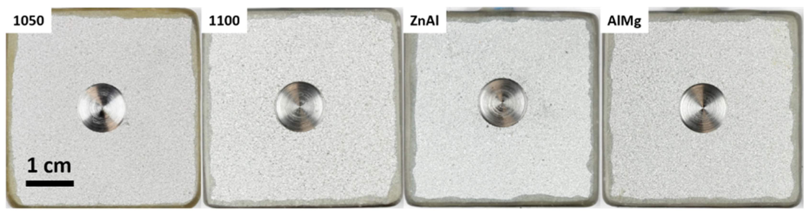
2.1. Thermal Spray Samples

Low carbon steel coupons with nominal composition shown in Table 1 were used as substrates for the ~300 μm coatings. Dimensions of samples varied depending on the exposure environment, specified in the following subsection.
Prior to the thermal spray process, angular alumina (NK36 type, 0.250–0.297 mm) at 100 psi (690 KPa) pressure was used for the grit blasting of the steel substrates in order to achieve a standard cleanliness of SA 2.5. These substrates were coated with four alloys in wire form (2.3 mm Ø) and chemical compositions are shown in Table 2. For each thermally sprayed sample, two identical wires were used during deposition. The use of four different alloy wires resulted in four thermal spray coatings designated as AA1150, AA1100, ZnAl and AlMg. These coatings were deposited by twin wire arc spray (TWAS) with an ARC140 gun (Metallisation Ltd., Dudley, UK) using parameters shown in Table 3. The process consisted of creating an electric arc between two charged wires (one positive, one negative), with a stream of compressed air directing the molten (or semi molten) particles towards the substrate. The deposition efficiency of the coating production process was between 40–50%. Circular artificial defects were machined post-spray with a flat (slot) drill at the center of each sample (~5% of sample surface area) in order to simulate coating failure.
The roughness of the prepared substrates and TS coatings was measured by 3D profilometry (Alicona InfiniteFocusSL and Alicona Imaging GmbH Software, Bruker Alicona, Graz, Austria). These measurements were repeated three times. The grit-blasted steel surface showed a value of Ra = 3.5 ± 0.5 μm, while TS coatings showed values of Ra between 15–25 μm.

2.2. Simulated Environment Tests
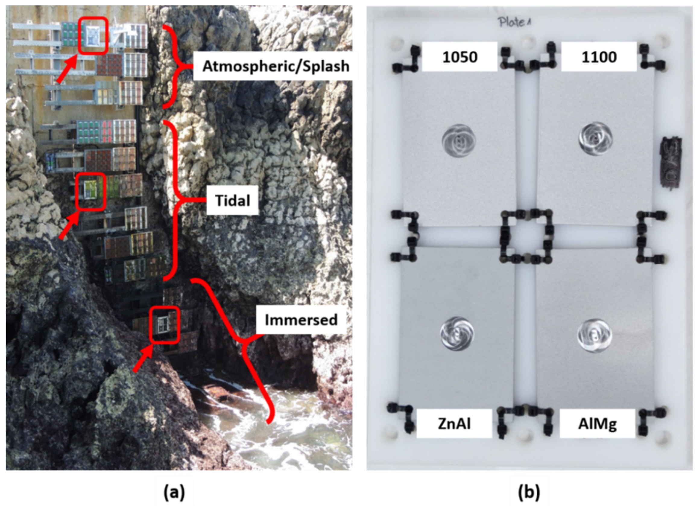
Thermal spray (TS) samples used for laboratory tests were 40 × 40 × 6 mm3, with a 5% of surface area defect and threaded rods inserted on one side of the samples to be used as the electrical connection with the potentiostat. All sides (except the TS-coated one) were covered by type 45 stopping-off lacquer to expose only the TS-coated side of the sample to artificial seawater. Figure 1 shows the appearance of the four types of TS-coated samples prepared for laboratory tests. Electrochemical measurements were carried out with an Autolab PGSTAT204 (Metrohm, Herisau, Switzerland) and analyzed with Nova 2.1 software provided by the same company. All electrochemical measurements were carried out using a three-electrode cell configuration. TS samples were used as a static working electrode, Ag/AgCl (KCl sat.) as a reference and a platinum/titanium wire as counter electrode. Individual cells open to the air were kept at ambient temperature of 20 ± 5 °C, using artificial seawater ASTM D1141 [21] as electrolyte. All potentials in this work are referred to the Ag/AgCl (Sat. KCl) electrode (Eref = +0.199 V vs. SHE, i.e., −0.045 V vs. SCE at 20 °C).
Electrochemical characterization of the samples was carried out by polarization curves in order to obtain corrosion potential (Ecorr), corrosion current density (jcorr) and Tafel coefficients (βa and βc) according to the Butler–Volmer equation (Equation (1)). Samples were immersed for 24 h to reach a stable state before recording the potential versus current curves. Samples were polarized to ± 250 mV from the corrosion potential (Ecorr), at 10 mV min−1 scan rate.
I = I corr   ( e 2.303 ( E E corr ) β a e 2.303 ( E E corr ) β c )
Electrochemical monitoring of samples exposed for 50 days in the laboratory was carried out by Open Circuit Potential (OCP) and Linear Polarization Resistance (LPR) measurements every 24 h. LPR scans were performed in the range of ± 15 mV from Ecorr, with a 10 mV·min−1 scan rate. Short-term tests such as polarization curves were repeated twice for reproducibility, while long-term tests were carried out once due to limited resources.

2.3. Field Trials

TS AA1050 samples (40 × 40 × 6 mm3) with 5% of surface area defects were immersed at “Les Minimes”, La Rochelle (France). Sea temperature was 13 ± 3 °C. Samples were in immersed conditions for 90 days (February 2019–April 2019), monitored every 10 days by Open Circuit Potential (OCP) and Linear Polarization Resistance (LPR) measurements with a ±15 mV range from OCP at 10 mV·min−1. Electrochemical measurements were carried out with a Gamry Interface1000 potentiostat/galvanostat and Gamry Analyst software for analysis (Gamry Instruments, Warminster, PA, USA). A platinum mesh was used as a counter electrode and an Ag/AgCl (sat. KCl) as a reference electrode, as shown in Figure 2.
In order to study the performance of TS coatings in different marine zones, four different alloys were exposed at “El Bocal” (Santander, Spain). These samples were 150 × 100 × 6 mm3, TS-coated on all surfaces and with a 5% of surface area defect on both top and bottom surfaces of the samples. TS samples were grouped in four to be exposed to the different marine environments as shown in Figure 3. Exposure time for these samples was 6 months (November 2018–May 2019) to atmospheric/splash, tidal and immersed conditions. It should be noted that during very low tides (less than 10% of the total exposure time), the water level goes below the samples exposed in the immersed zone as shown in Figure 3. Monitoring of the samples was carried out by photographs taken periodically. Seawater temperature was 14 ± 3 °C.

2.4. Surface Characterization

Surface topography and chemical composition of the samples were evaluated after exposure to different environments. Corrosion products formed on the surface of the specimens were characterized by scanning electron microscopy and energy dispersive X-ray spectroscopy (SEM/EDX), Raman spectroscopy and X-ray diffraction (XRD).
Topographical and chemical analyses were performed using an EVO LS15 SEM/EDX (Zeiss, Obekochen, Germany) using 20 kV voltage, 4.5 μm spot size, 8.5 mm working distance and backscattered electron detector. Micro-Raman spectra were recorded using a Jobin–Yvon Raman spectrometer (LabRAM-HR, Horiba, Tokyo, Japan) equipped with an Olympus-BX41 microscope (Olympus, Tokyo, Japan) and a Peltier-based cooled charge coupled device (CCD) detector (Horiba, Tokyo, Japan). Spectra were recorded at room temperature, with excitation provided by a He-Ne laser (632.8 nm) with reduced power between 25% and 1% to prevent excessive heating. X-ray diffraction (XRD) analysis was performed with an Inel EQUINOX 6000 diffractometer (Thermo Fisher Scientific, Waltham, MA, USA) equipped with a CPS 590 curved detector. This detector is designed for the simultaneous detection of the diffracted photons on a 2θ range of 90°. Acquisition was made with a constant angle of incidence (5°) for 45 min using Co-Kα radiation (λ = 0.17903 nm). The various phases were identified via the ICDD-JCPDS (International Center for Diffraction Data-Joint Committee on Powder Diffraction Standards) database [22].
For examination of cross sections, samples were cold mounted with Epofix resin (Struers Inc., Cleveland, OH, USA) and cut through the middle with a vertical abrasive cutting saw (Buehler Abrasmatic 300, Lake Bluff, IL, USA). The surface was then ground with SiC abrasive papers going from P120 to P2500, and polished successively with 3, 1 and 0.25 µm diamond paste.

3. Results

3.1. Simulated Environments Tests

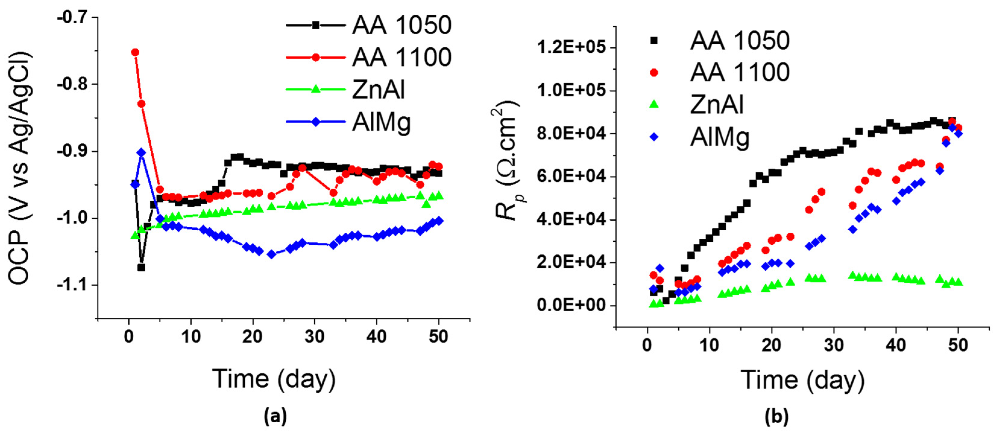
3.1.1. Electrochemical Characterization of Coatings

Initial characterization of the materials was carried out by potentiodynamic polarization. Figure 4 shows the polarization curves of the four samples recorded in artificial seawater after 24 h of immersion, and Table 4 shows the corrosion parameters obtained from these. Here, Tafel slopes were converted to Tafel coefficients (ba,c = ln(10)/βa,c) for comparison with the literature data. Corrosion potential (Ecorr) values of AA1050, AA1100 and AlMg are all within the range of −0.97 ± 0.01 V, whereas Ecorr of ZnAl alloy decreases to −1.10 V due to the higher nobility of aluminum than that of zinc. These are all mixed potential values due to the presence of defects on all coatings. When steel is exposed to seawater, a cathodic reaction, Equation (2), happens mainly on its surface while an anodic reaction happens on the coatings, Equations (3) and (4):
O 2 ( g ) + 2 H 2 O ( l ) + 4 e 4 OH ( aq )   E o =   +   0.40   V
Al ( s ) Al 3 + ( aq ) + 3 e   E o =   +   1.66   V
Zn ( s ) Zn 2 + ( aq ) + 2 e   E o =   +   0.76   V
Current density values obtained through Tafel analysis increase in two orders of magnitude from the Al alloys to the ZnAl alloy (Table 4). This is due to the tendency of Al alloys to passivate in seawater [8,23], whereas the Zn-based alloy shows an active behavior. The current density values of aluminum alloys (AA 1050, AA 1100 and AlMg) tend to reach a limiting current density as potential values shift towards less negative values. This is due to the passivation of aluminum in seawater which reduces material degradation and translates into lower corrosion current densities and corrosion rates. It should be noted that the breakdown of the aluminum passive film is not observed due to the limited range of the potentiodynamic sweep. When wider limits of potentiodynamic scans are applied for TSA coatings in seawater (above −0.75 V and below −1.45 V vs. Ag/AgCl), the film breakdown is observed, as it has been reported in the previous literature [24,25]. For the ZnAl alloy however, the correlation between potential and current density values corresponds to a typical active material [8,26], since current density increases significantly as the potential is swept towards less negative values. The formation of a protective layer of corrosion products is less efficient for Zn alloys, as zinc chlorides dissolve in aqueous solution [27]. As a result, aluminum alloys are expected to give longer service life than zinc alloys in immersed conditions.
Looking at the cathodic branches of the polarization curves, the slopes of all curves present similar values. As the cathodic reaction happens mainly on the steel surface, the area of which is identical in all samples, this is expected.

3.1.2. Long-Term Tests

Long-term corrosion protection provided by thermal spray coatings in artificial seawater was evaluated by OCP and LPR monitoring over 50 days of exposure. Figure 5 shows the data collected for the four different alloys used to obtain the thermal spray coatings. In all cases, OCP values show a mixed potential, due to the presence of defects on the samples, and significant changes over the initial 10 days of exposure. Fluctuations of potential values in this initial stage correspond to changes on the surface of the coatings. Upon immersion, the air-formed oxide layer dissolves and the new aqueous oxide layer begins to form [18,19]. The formation of the aqueous oxide layer leads to passivation of the coatings, which helps to reduce the self-corrosion. From Figure 5a, the cathodic polarization effect of the four coatings can be observed as OCP values of all samples are below −0.90 V after 20 days of exposure. After this time, all samples present small fluctuations in potential values, which are mainly attributed to temperature changes and solution electrolyte top up. By the end of the test, after 50 days of exposure, both aluminum alloys (AA1050 and AA1100) present a similar potential value around −0.93 V, whereas ZnAl and AlMg alloys present values of −0.97 and −1.00 V, respectively. The more negative potentials obtained for the latter alloys are due to the more anodic (active) behavior of Zn and Mg elements present [14].
Polarization resistance values obtained through LPR measurements continuously increase over the entire duration of the tests for the three alloys containing Al as the main element (AA1050, AA1100 and AlMg). The AA1050 alloy shows the fastest and highest increase of Rp, reaching values over 85 kΩ·cm2 after 35 days of exposure. AA1100 and AlMg present an increasing tendency of Rp values as well, reaching a similar maximum value of Rp to AA1050 after 50 days of exposure. For the ZnAl alloy however, Rp values are significantly lower. For the alloy with Zn as the majority element, Rp values reach a maximum of 14 kΩ·cm2 after 35 days of exposure, with slight changes occurring during the rest of the exposure period. Therefore, as lower Rp values translate into higher corrosion rates, the corrosion rates of the ZnAl alloy would be significantly higher than those of Al alloys. Overall, from the data presented in Figure 5, the better performance of Al alloys can be observed. Even though the four alloys tested are able to polarize and protect the steel substrate in artificial seawater, the alloys containing Al in a higher proportion to Zn perform better as they present higher Rp values. As a result, Al alloys are more suitable for offshore structures in marine environments under immersed conditions.

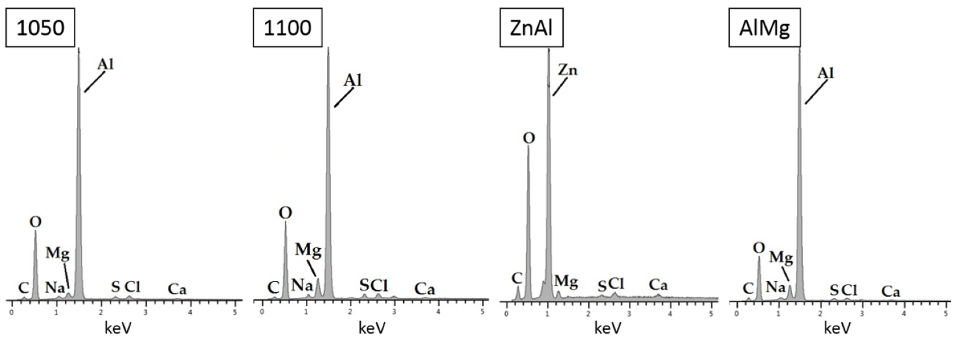
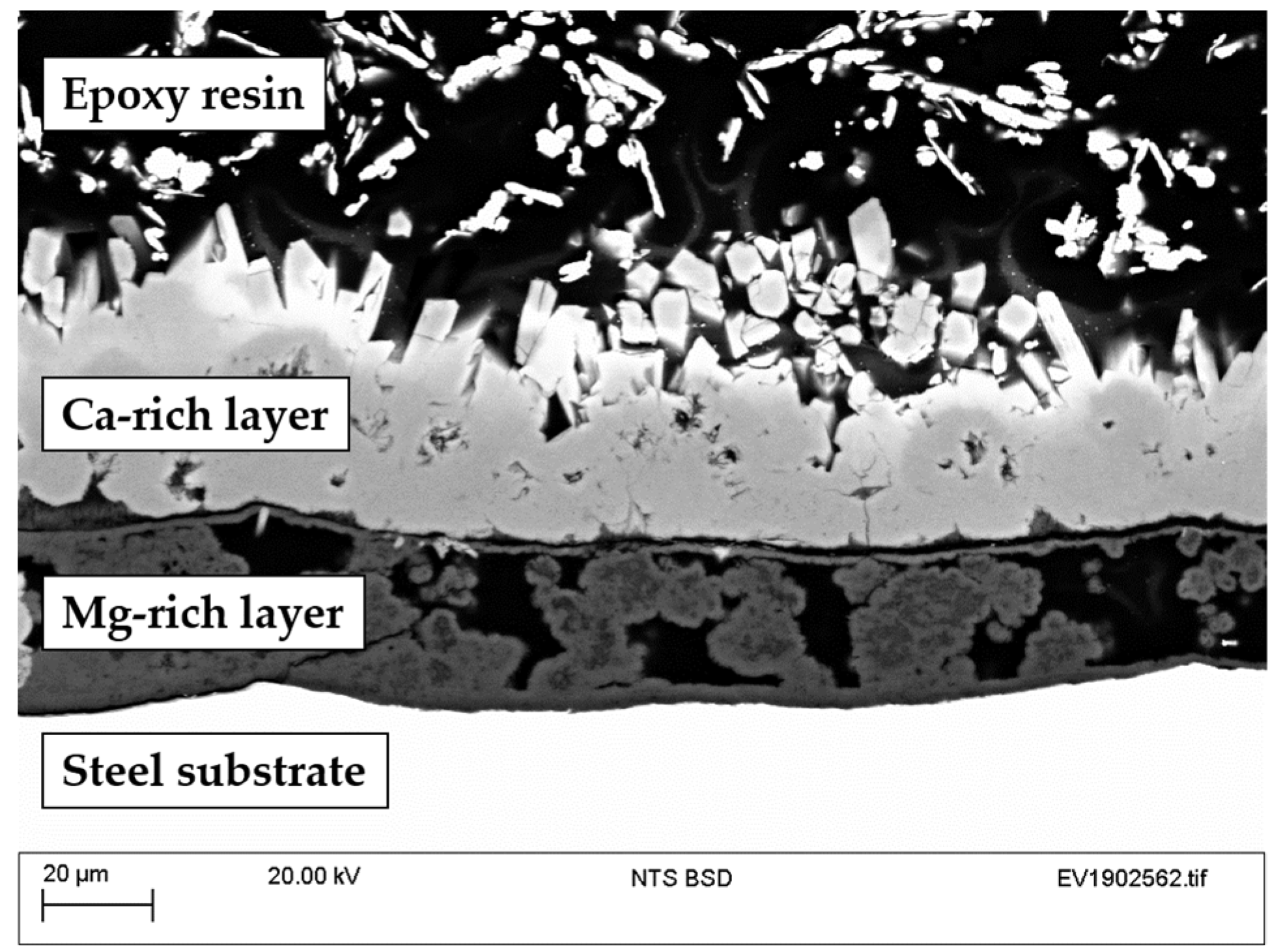
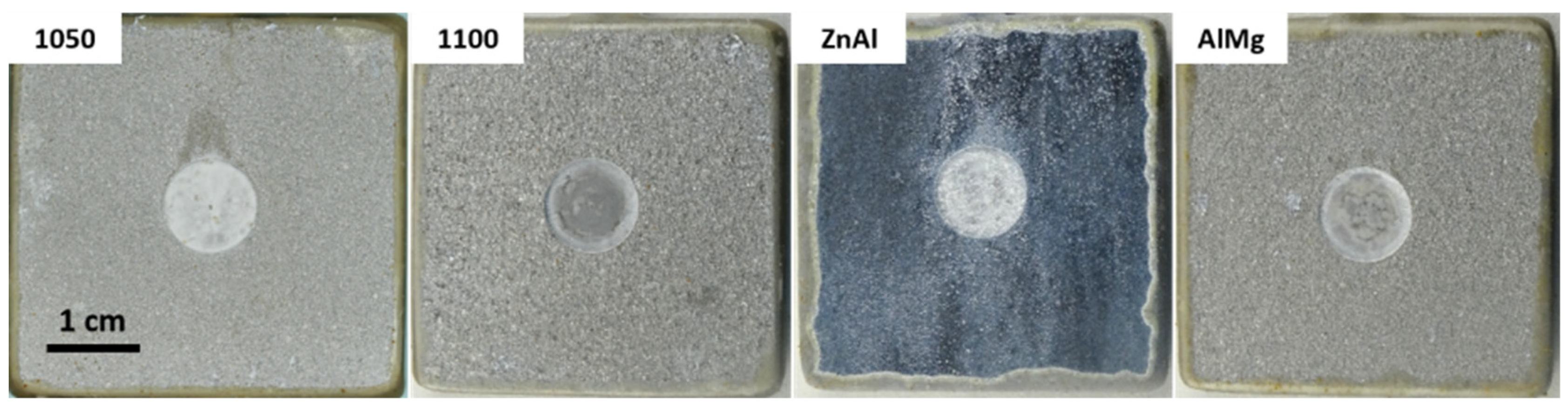
3.1.3. Surface Characterization

Figure 6 shows photographs of TS-coated samples after exposure to controlled laboratory tests with artificial seawater for 50 days. Here, it can be observed how the sample sprayed with the ZnAl alloy presents the more prominent coating color change and largest amount of white deposits on top of it. This is attributed to the formation of the Zn oxides/hydroxides/chlorides [12,27].
Samples were also examined by SEM/EDX, Raman and XRD analysis to identify corrosion deposits formed on top of the coatings and on top of the steel on defect areas. From the SEM/EDX analysis, all the Al alloys (AA1050, AA1100 and AlMg) revealed Al oxides/hydroxides on the surface (Figure 7). The small amount of Mg identified from EDX could be due to the presence of hydrotalcite.
On the defect areas, white deposits can be observed on all samples in Figure 6. Based on the literature, these are expected to be a bi-layer of calcareous deposits with brucite [Mg(OH)2] in the inner layer and aragonite (CaCO3) in the outer layer. This was confirmed by SEM/EDX of the cross sections of all samples. Figure 8 shows the defect area on the cross section of Al sample 1100 as an example of the calcareous deposits formation.
In addition, Raman and XRD analysis validated the presence of aragonite as shown in Figure 9. On the Raman spectra, the peaks at 152, 254, 705 and 1085 cm−1 correspond to the aragonite structure [28]. On the XRD pattern obtained, aragonite and halite were identified. The presence of brucite however could not be confirmed by Raman or XRD analysis. This is believed to be due to the small amounts present and the formation of aragonite on top of it.

3.2. Field Trials

In order to provide a better understanding of the performance of TS coatings to protect carbon steel structures in marine environments, laboratory tests were complemented with field tests by performing electrochemical tests on site on TS AA1050 samples with defects at Les Minimes (La Rochelle, France) and exposing TS-coated samples with defects in different zones of marine environments at El Bocal (Santander, Spain).

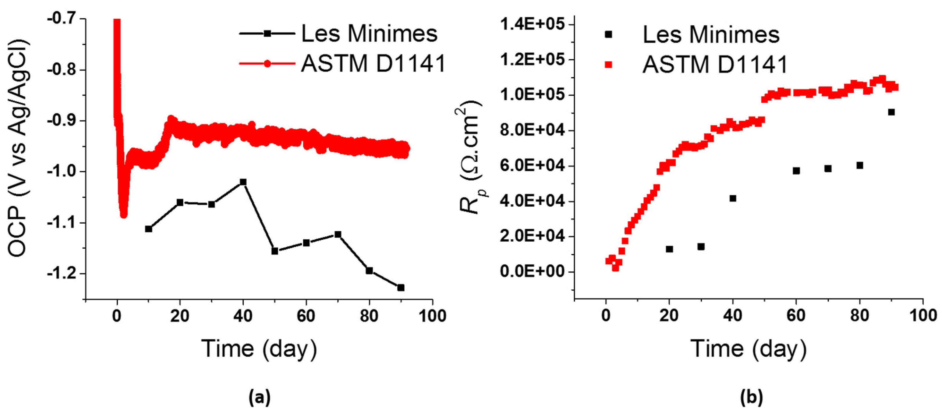
3.2.1. Electrochemical Tests In Situ

The influence of the environment on the long-term performance of TS coatings was studied by electrochemical measurements recorded in situ in a real marine environment (Les Minimes, France). As it was not feasible to perform the measurements under these conditions for all coatings and all marine exposure zones due to material and time limitations, the TS AA1050 was selected for these tests. These results were compared to the ones obtained through controlled laboratory tests with artificial seawater.
OCP and LPR data were collected over 90 days of exposure with TS AA1050 (Figure 10). Laboratory tests in artificial seawater start recording values of −0.70 V, reaching a minimum of −1.10 V and then increasing to stabilize around −0.95 V. This trend correlates with data from the literature [18,19], as discussed on Section 3.1.2 of this article. Initial values of samples exposed to a real marine environment could not be recorded due to technical problems with reference and counter electrodes. Measurements performed after 10 days of exposure show more negative potentials than the ones recorded under controlled environment in the laboratory. This could be explained due to the defect area covered by deposits more rapidly in real marine environments. The combination of living organisms and more O2 access can influence the kinetics of the calcareous deposit formation on top of steel [29,30]. Therefore, the cathodic reaction on the steel surface decreases, and occurs on the TS coating instead. As a result, the potential observed for samples exposed to real marine environment become more negative. This is also reflected on polarization resistance values recorded by LPR. For the samples exposed to a real marine environment, even though Rp values increase over time as well, these are smaller than the values obtained from samples exposed to controlled laboratory tests. Overall, from Figure 10 it can be observed that the TSA coating is providing cathodic protection for the underlying steel substrate throughout the entire duration of the test and in both cases Rp values increase, which translates into a decrease in corrosion rate over time.

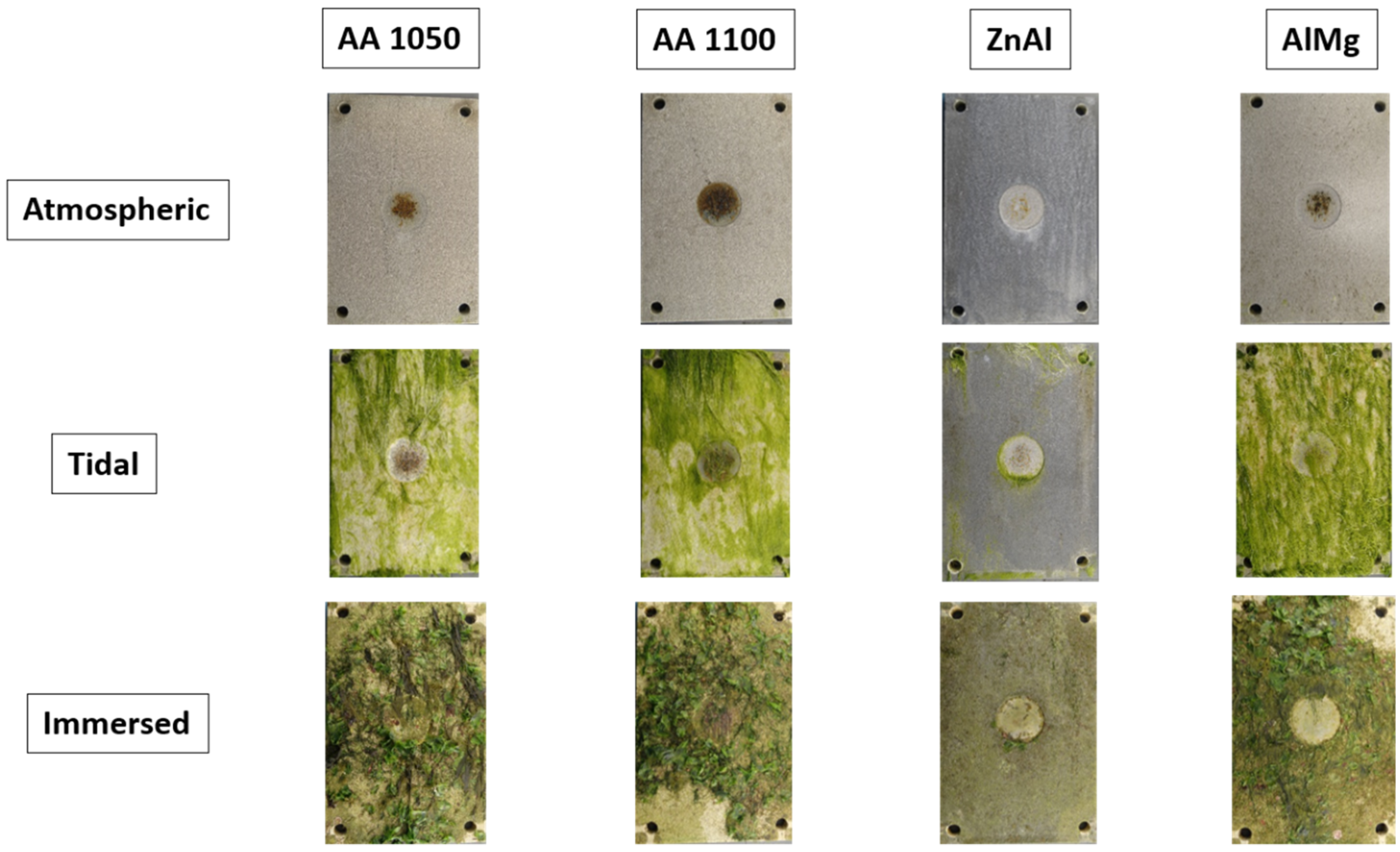
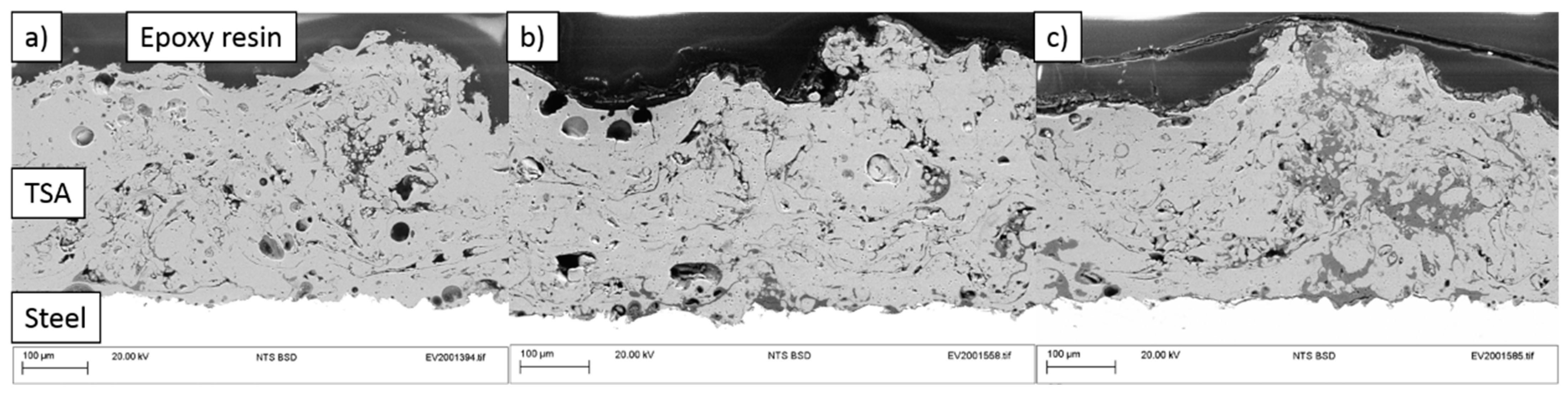
3.2.2. Long-Term Exposure of TS Coatings

Thermal spray-coated samples with four Al/Zn alloys were exposed to three different zones of marine environments at the Marine Corrosion Test Site “El Bocal” in Santander (Spain): Atmospheric/splash, tidal and immersed, as shown in Figure 3. The total exposure period was 6 months and evolution of samples over time was carried out by periodic photographs. Figure 11 shows the images of the four alloys tested in atmospheric, tidal and immersed conditions at the end of the tests. Initial analysis of the corrosion performance of the coatings was based on appearance, looking into TS coating deposits (oxides, hydroxides of Zn or Al), biofouling, rusting and calcareous deposits. Overall blistering, additional damage or rust was not observed on top of the TS coatings tested. The alloys with Al as the main constituent do not present significant changes in terms of coating appearance or deposits over the 6-month exposure period. For the ZnAl alloy however, the coating appearance presents changes in color as exposure time increases and corrosion deposits on top of the coatings are visible on samples in atmospheric and tidal conditions. In all cases, biofouling on exposed samples increases from the atmospheric to the immersed zones, with the ZnAl alloy showing the least amount.
Rust is visible in the defect areas of the Al alloys in atmospheric and tidal regions (AA1050, AA1100 and AlMg). The ZnAl alloy does not present signs of rust on any of three exposure zones. This suggests that Zn alloys are more efficient in atmospheric/splash zones than Al alloys. White deposits observed in the defect areas are assumed to be calcareous in nature based on the literature and prior studies by the authors. This was also confirmed by SEM/EDX analysis. Overall, from visual inspection no major corrosion/degradation were observed on this set of samples.
From cross sections of these samples, the microstructure of the coatings and their thickness was evaluated. Figure 12 shows the cross section of a TS AA1050-coated steel sample before corrosion tests. The microstructure of this coating presents low porosity and a rough surface.
SEM images of the cross sections of TS coatings after 6 months of exposure at El Bocal revealed uniform microstructure of coatings, with no signs of cracking or delamination on any sample. Figure 13 shows an example of TS AA1050 coating exposed to atmospheric/splash, tidal and immersed conditions. Here, the amount of corrosion products filling the pores in the TS coating increase from Figure 13a–c. Coating thickness measurements performed by image analysis revealed a decreasing tendency from samples exposed to atmospheric (320 ± 10 μm) conditions to the ones exposed to immersed conditions (280 ± 10 μm). However, there were no major signs of corrosion at the steel–coating interface. These observations were also found to be true for the remaining three coatings tested (please find the link provided in Data Availability Statement).

4. Conclusions

Offshore structures are expected to perform for at least 25 years with minimal maintenance in order to minimize risks and costs. However, the complexity of marine environments makes offshore testing challenging for researchers. Recreating this environment through laboratory experiments always implies making some assumptions, as conditions vary from different geographical locations. These results provide an insight into the real life performance of TSA and TSZ (Zn-15Al) coatings by combination of laboratory and field tests including electrochemical measurements. The following conclusions could be drawn from the work presented in this paper:
  • The four coating types tested showed that they provided cathodic protection for steel in marine environments based on laboratory and field tests.
  • The laboratory tests performed with different Al alloys (AA1050, AA1100, Al-5Mg) and Zn-15Al coatings confirmed that although TS Zn-15Al is able to polarize steel to more negative potentials, it provides a shorter lifetime under immersed conditions as evidenced from the Rp values. Therefore, for the design of offshore structures, the exposure zone (atmospheric, tidal or immersed) should be considered in order to choose the coating that provides the best protection.
  • Surface characterization of samples revealed the formation of aluminum and zinc oxides/hydroxides on top of the coatings and calcareous deposits on the steel surface in the defect areas.
  • The comparison of electrochemical data for TS AA1050 in controlled laboratory tests and field tests substantiates a good correlation in terms of OCP and Rp.
  • TSA and TSZ (Zn-15Al) samples with defects showed no significant signs of corrosion after a 6-month exposure to the different zones of marine environments (atmospheric, tidal and immersed).

Author Contributions

Conceptualization, R.G.-E. and S.P.; methodology, R.G.-E., S.P., P.R., M.J. and A.R.; formal analysis, R.G.-E.; writing—original draft preparation, R.G.-E.; writing—review and editing, R.G.-E., S.P., P.R., R.T. and A.R.; supervision, S.P. and R.T. All authors have read and agreed to the published version of the manuscript.

Funding

This publication was made possible by the sponsorship and support of Lloyd’s Register Foundation, a charitable foundation helping to protect life and property by supporting engineering-related education, public engagement and the application of research. The work was enabled through, and undertaken at, the National Structural Integrity Research Centre (NSIRC), a postgraduate engineering facility for industry-led research into structural integrity established and managed by TWI through a network of both national and international universities. Authors gratefully acknowledge financial support from the Centre for Doctoral Training in Innovative Metal Processing (IMPaCT) funded by the UK Engineering and Physical Sciences Research Council (EPSRC), Grant reference E/L016206/1.

Institutional Review Board Statement

Not applicable.

Informed Consent Statement

Not applicable.

Data Availability Statement

The data presented in this study are openly available at https://doi.org/10.25392/leicester.data.14049647.

Acknowledgments

The authors are grateful for all the support provided by the teams working at TWI, LaSIE and Centro Tecnologico CTC.

Conflicts of Interest

The authors declare no conflict of interest.

References

  1. Presuel-Moreno, F.; Jakab, M.; Tailleart, N.; Goldman, M.; Scully, J. Corrosion-resistant metallic coatings. Mater. Today 2008, 11, 14–23. [Google Scholar] [CrossRef]
  2. Momber, A.; Plagemann, P.; Stenzel, V. Performance and integrity of protective coating systems for offshore wind power structures after three years under offshore site conditions. Renew. Energy 2015, 74, 606–617. [Google Scholar] [CrossRef]
  3. Lee, H.S.; Ismail, M.A.; Choe, H.B. Arc thermal metal spray for the protection of steel structures: An overview. Corros. Rev. 2015, 33, 31–61. [Google Scholar] [CrossRef]
  4. Herman, H.; Sulit, R.A. Thermal spray coatings. Weld. Brazing Solder. 1993, 6, 1004–1009. [Google Scholar] [CrossRef]
  5. Shibli, S.; Meena, B.; Remya, R. A review on recent approaches in the field of hot dip zinc galvanizing process. Surf. Coat. Technol. 2015, 262, 210–215. [Google Scholar] [CrossRef]
  6. Paredes, R.; Amico, S.; D’Oliveira, A. The effect of roughness and pre-heating of the substrate on the morphology of aluminium coatings deposited by thermal spraying. Surf. Coat. Technol. 2006, 200, 3049–3055. [Google Scholar] [CrossRef]
  7. Shrestha, S.; Sturgeon, A. Characteristics and electrochemical corrosion behaviour of thermal sprayed aluminium (TSA) coat-ings prepared by various wire thermal spray processes electrochemical polarization. EUROCORR 2005, 2005, 1–8. [Google Scholar]
  8. López-Ortega, A.; Arana, J.; Rodríguez, E.; Bayón, R. Corrosion, wear and tribocorrosion performance of a thermally sprayed aluminum coating modified by plasma electrolytic oxidation technique for offshore submerged components protection. Corros. Sci. 2018, 143, 258–280. [Google Scholar] [CrossRef]
  9. López-Ortega, A.; Bayón, R.; Arana, J. Evaluation of protective coatings for offshore applications. Corrosion and tribocorrosion behavior in synthetic seawater. Surf. Coat. Technol. 2018, 349, 1083–1097. [Google Scholar] [CrossRef]
  10. Malek, M.H.A.; Saad, N.H.; Abas, S.K.; Roselina, N.N.; Shah, N.M. Performance and microstructure analysis of 99.5% aluminium coating by thermal arc spray technique. Procedia Eng. 2013, 68, 558–565. [Google Scholar] [CrossRef] [Green Version]
  11. Moon, K.-M.; Kim, Y.-H.; Lee, M.-H.; Baek, T.-S. Polarization characteristics of four types of coating films by thermal spray in seawater solution. Mod. Phys. Lett. B 2015, 29, 1–6. [Google Scholar] [CrossRef]
  12. Azevedo, M.S.; Allély, C.; Ogle, K.; Volovitch, P. Corrosion mechanisms of Zn (Mg, Al) coated steel: 2. The effect of Mg and Al alloying on the formation and properties of corrosion products in different electrolytes. Corros. Sci. 2015, 90, 482–490. [Google Scholar] [CrossRef]
  13. Katayama, H.; Kuroda, S. Long-term atmospheric corrosion properties of thermally sprayed Zn, Al and Zn–Al coatings exposed in a coastal area. Corros. Sci. 2013, 76, 35–41. [Google Scholar] [CrossRef]
  14. Quale, G.; Årtun, L.; Iannuzzi, M.; Johnsen, R. Cathodic protection by distributed sacrificial anodes—A new cost-effective solution to prevent corrosion of subsea structures. Corros. NACE 2017, 2017, 1–15. [Google Scholar]
  15. Fischer, K.P.; Thomason, W.H.; Rosbrook, T.; Murali, J. Performance history of thermal-sprayed aluminum coatings in off-shore service. Mater. Perform. 1995, 34, 27–35. [Google Scholar]
  16. Frost, R.L.; Weier, M.L.; Kloprogge, J.T. Raman spectroscopy of some natural hydrotalcites with sulphate and carbonate in the interlayer. J. Raman Spectrosc. 2003, 34, 760–768. [Google Scholar] [CrossRef] [Green Version]
  17. Hartt, W.H.; Culberson, C.H.; Smith, S.W. Calcareous deposits on metal surfaces in seawater—A critical review. Corrosion 1984, 40, 609–618. [Google Scholar] [CrossRef]
  18. Echaniz, R.G.; Paul, S.; Thornton, R. Effect of seawater constituents on the performance of thermal spray aluminum in marine environments. Mater. Corros. 2019, 1–9. [Google Scholar] [CrossRef] [Green Version]
  19. Ce, N.; Paul, S. The effect of temperature and local pH on calcareous deposit formation in damaged thermal spray aluminum (TSA) coatings and its implication on corrosion mitigation of offshore steel structures. Coatings 2017, 7, 52. [Google Scholar] [CrossRef] [Green Version]
  20. BS EN 10025-1:2004. Hot Rolled Products of Structural Steels—Part 1: General Technical Delivery Conditions; BSI: London, UK, 2004. [Google Scholar]
  21. ASTM D1141-98. Standard Practice for the Preparation of Substitute Ocean Water; ASTM International: West Conshohocken, PA, USA, 2013. [Google Scholar]
  22. Gates-rector, S.; Blanton, T. The powder diffraction file: A quality materials characterization database. Powder Diffr. 2019, 34, 352–360. [Google Scholar] [CrossRef] [Green Version]
  23. Lee, H.-S.; Singh, J.K.; Park, J.H. Pore blocking characteristics of corrosion products formed on aluminum coating produced by arc thermal metal spray process in 3.5 wt.% NaCl solution. Constr. Build. Mater. 2016, 113, 905–916. [Google Scholar] [CrossRef]
  24. Dehnavi, V.; Shoesmith, D.W.; Luan, B.L.; Yari, M.; Liu, X.Y.; Rohani, S. Corrosion properties of plasma electrolytic oxidation coatings on an aluminium alloy–The effect of the PEO process stage. Mater. Chem. Phys. 2015, 161, 49–58. [Google Scholar] [CrossRef]
  25. Silva, F.; Bedoya, J.; Dosta, S.; Cinca, N.; Cano, I.; Guilemany, J.; Benedetti, A. Corrosion characteristics of cold gas spray coatings of reinforced aluminum deposited onto carbon steel. Corros. Sci. 2017, 114, 57–71. [Google Scholar] [CrossRef] [Green Version]
  26. Esfahani, E.A.; Salimijazi, H.; Golozar, M.A.; Mostaghimi, J.; Pershin, L. Study of corrosion behavior of arc sprayed aluminum coating on mild steel. J. Therm. Spray Technol. 2012, 21, 1195–1202. [Google Scholar] [CrossRef]
  27. Liu, S.; Zhao, X.; Zhao, H.; Sun, H.; Chen, J. Corrosion performance of zinc coated steel in seawater environment. Chin. J. Oceanol. Limnol. 2016, 35, 423–430. [Google Scholar] [CrossRef]
  28. De La Pierre, M.; Carteret, C.; Maschio, L.; André, E.; Orlando, R.; Dovesi, R. The raman spectrum of CaCO3 polymorphs calcite and aragonite: A combined experimental and computational study. J. Chem. Phys. 2014, 140, 164509. [Google Scholar] [CrossRef] [PubMed] [Green Version]
  29. Refait, P.; Jeannin, M.; Sabot, R.; Antony, H.; Pineau, S. Electrochemical formation and transformation of corrosion products on carbon steel under cathodic protection in seawater. Corros. Sci. 2013, 71, 32–36. [Google Scholar] [CrossRef]
  30. Barchiche, C.; Deslouis, C.; Festy, D.; Gil, O.; Refait, P.; Touzain, S.; Tribollet, B. Characterization of calcareous deposits in artificial seawater by impedance techniques: 3-Deposit of CaCO3 in the presence of Mg (II). Electrochim. Acta 2003, 48, 1645–1654. [Google Scholar] [CrossRef]
Figure 1. Thermally sprayed coated samples with 5% of surface area defect before exposure.
Coatings 11 00320 g001
Figure 2. Experimental setup to carry out electrochemical measurements at Les Minimes (La Rochelle, France).
Coatings 11 00320 g002
Figure 3. (a) Marine corrosion test site El Bocal (Santander, Spain), pointing out the location of TS (thermal spray) samples. (b) TS samples before exposure at El Bocal.
Coatings 11 00320 g003
Figure 4. Polarization curves of Al/Zn alloys in artificial seawater.
Coatings 11 00320 g004
Figure 5. Electrochemical monitoring of long-term performance of TS coatings in artificial seawater by (a) OCP (Open Circuit Potential) measurements and (b) LPR (Linear Polarization Resistance) measurements.
Coatings 11 00320 g005
Figure 6. Images of TS samples after 50 days exposure to laboratory tests.
Coatings 11 00320 g006
Figure 7. EDX (energy dispersive X-ray spectroscopy) results obtained from top view analysis of TS coatings after 50 days of exposure to artificial seawater in controlled laboratory conditions.
Coatings 11 00320 g007
Figure 8. SEM (scanning electron microscopy) cross-sectional image of defect area of a TS sample exposed for 50 days to artificial seawater under controlled laboratory conditions.
Coatings 11 00320 g008
Figure 9. Raman and XRD (X-ray diffraction) of defect area of sample exposed to artificial seawater (SW) for 50 days in controlled laboratory conditions.
Coatings 11 00320 g009
Figure 10. (a) OCP and (b) LPR data of TS AA1050 with 5% of surface area defect immersed in artificial seawater ASTM D1141 (lab conditions) and a real marine environment (Les Minimes, France).
Coatings 11 00320 g010
Figure 11. Images of TS samples of Al-Zn alloys with defects after exposure at El Bocal (Spain) for 6 months.
Coatings 11 00320 g011
Figure 12. Cross section SEM image of TSA 1050 coating on a steel substrate prior to corrosion testing.
Coatings 11 00320 g012
Figure 13. Cross-sectional SEM images of TSA1050 samples immersed at El Bocal (Santander, Spain) for 6 months in (a) atmospheric/splash, (b) tidal and (c) immersed conditions.
Coatings 11 00320 g013
Table 1. Nominal composition of steel substrates for thermal spray process (S355N, EN 10025-3:2004 [20]).
ElementsCMnSiPSCrNiCuAlMo
wt.%0.1501.3500.0300.0160.0050.0800.0600.1700.0350.014
Table 2. Chemical composition in weight % of alloys used for thermal spray coatings.
AlloyAl (wt.%)Zn (wt.%)Mg (wt.%)Cu (wt.%)
AA105099.5 min0.050.050.02
AA110099.0 min0.1-0.2 max
ZnAl15.085.0--
AlMg95.0-5.0-
Table 3. Thermal spray process parameters.
AlloyWire Diameter (mm)Wire Feed Rate (m min−1)Spray Distance (mm)Increment Step (mm)Traverse Speed (m s−1)Voltage (V)Current (A)
AA1050
AA1100
AlMg
2.35.095.010.00.4533.0200
ZnAl2.35.095.08.00.4532.0160
Table 4. Corrosion parameter from polarization curves of TS samples in artificial seawater. The error for jcorr and ba,c is estimated at ±20%, while that on Ecorr is ±1 mV.
Coating AlloyEcorr (V)jcorr (A cm−2)ba (mV/dec)bc (mV/dec)
AA1050−0.985.50 × 10−6570180
AA1100−0.976.20 × 10−6510140
ZnAl−1.101.50 × 10−490130
AlMg−0.985.30 × 10−6380150
Publisher’s Note: MDPI stays neutral with regard to jurisdictional claims in published maps and institutional affiliations.

