Article

Investigation into Microstructure, Wear Resistance in Air and NaCl Solution of AlCrCoNiFeCTax High-Entropy Alloy Coatings Fabricated by Laser Cladding

School of Materials Engineering, Shanghai University of Engineering Science, Shanghai 201620, China
*
Author to whom correspondence should be addressed.
Coatings 2021, 11(3), 358; https://doi.org/10.3390/coatings11030358
Submission received: 23 February 2021 / Revised: 14 March 2021 / Accepted: 17 March 2021 / Published: 21 March 2021
(This article belongs to the Special Issue Wear Behavior of Polymer Composites)

Abstract

:
AlCrCoNiFeCTax (x = 0, 0.5 and 1.0) high-entropy alloys coatings were synthesized on 45# steel by laser cladding. The microstructural evolution of the coatings with the change in x was analyzed in detail. The effect of Ta content on the wear behaviors of the coatings at different circumstances (in air and 3.5 wt.% NaCl solution) was especially highlighted. The microstructure presented the following change: equiaxed BCC (Body Centered Cubic) grains + fine MC (carbide, M = Al, Cr, Co and Ni) particles (x = 0) → equiaxed BCC grains + coarse TaC blocks + fine TaC particles (x = 0.5) → flower-like BCC grains + coarse TaC blocks + eutecticum (BCC + TaC) (x = 1.0). The average microhardness of the coatings demonstrated an upward tendency with increasing x due to the combination of the stronger solid solution and dispersion strengthening from the significant difference in atomic radius between Ta and Fe and the formation of TaC with an extremely high hardness. The wear rates of the coatings were gradually reduced both in air and in NaCl solution along with the increase in Ta content, which were lower than those of the substrate. The wear rates of the coatings with x = 0.5 and 1.0 in NaCl solution were slightly reduced by about 17% and 12% when compared with those in air. However, the values of the substrate and the coating without Ta in NaCl solution were sharply enhanced by 191% and 123% when compared with those in air. This indicated that the introduction of Ta contributed to the improvement in wear resistance both in air and in NaCl solution.

1. Introduction

Steel is extensively applied in industrial components such as shaft parts, gear wheels and screws on account of its good machinability, excellent comprehensive mechanical properties and high performance-to-cost ratio [1,2]. However, for some steels (such as 45# steel, Q235 steel and 316L stainless steel) with low hardness, poor wear resistance severely restricts their more extensive applications as friction components in engineering fields [3]. Moreover, when they are used in a harsh corrosive circumstance, the chemical dissolution will further accelerate their failure [4,5]. Many surface modification methods have been utilized to improve the wear resistance of some steels by preparing a high-hardness coatings on them (such as plasma metallizing technique [6], ion chemical heat treatment [7,8], ion deposition [9,10], thermal spraying [11], electroplating [12], magnetron sputtering [13], spark deposition [14] and electron beam treatment [15,16,17]). However, coatings prepared by the above methods usually have loose microstructures, small thickness and poor bonding with the substrate, which limit their applications under harsh circumstances. Laser cladding has aroused wide interest as a promising surface modification technique and presented a rapid development in the last twenty years. The chemical compositions and phase constituents of the coatings can be regulated flexibly by selecting different cladding materials. Their thickness can also be adjusted on a large scale. Most importantly, the coatings have a compact microstructure and demonstrate good metallurgical bonding with the substrate [18,19]. Previous studies mainly focused on the design and preparation of metal matrix composite coatings reinforced by different hard ceramic particles. Those coatings with a high hardness will be endowed with excellent resistance to micro-cutting. However, the toughness will be lost coupled with the high hardness of the coatings. Moreover, residual stress is easily generated in the coatings due to the rapid heating and cooling characteristics of laser cladding. Low toughness and high residual stress result in the coatings possessing high cracking susceptibility. When the coatings serve under a long-term wear condition, the high cracking susceptibility makes cracks easily initiate and propagate in the coatings, resulting in severe brittle-debonding of the coatings from the substrate. Therefore, it is very necessary to design and explore a new alloy coating with a proper balance between hardness and toughness. The concept of high-entropy alloys (HEAs) was proposed by Yeh et al. [20], which rapidly became a research hotspot. This alloy, as a new category, is composed of least five principal elements, which is different from that designed by the traditional philosophy. Ding et al. published an article in Nature (2019) [21] titled “Tuning element distribution, structure and properties by composition in high-entropy alloys”, in which the mechanism of the combination of high strength and excellent plasticity was revealed. This research reveals the coexistence mechanism of high strength and high toughness in high-entropy alloys. This also proposes a new strategy to solve the incompatibility between hardness and toughness involved in hard ceramic particle-reinforced metal matrix coatings prepared by laser cladding—namely, laser cladding high-entropy alloy coatings on steels by optimizing the component and designing the processing.
Considerable research has been carried out to improve the wear resistance of steels by laser cladding high-entropy alloy coatings on them. Juan et al. [22] synthesized an FeCrCoAlNiMo HEA coating on 45# steel by laser cladding. The coating was composed of a single solid solution (BCC), and its microhardness of 706 HV0.2 was 3.5 times that of the substrate (about 200 HV0.2). The average wear volume of the coating was decreased by 187% in comparison with that of the substrate in dry friction. Qiu [23] fabricated a laser-clad CoCrFeNiMo HEA coating on 45# steel. The coating, composed of FCC (Face Centered Cubic), BCC and Laves phase, had high hardness (741 HV), which was far higher than that of the substrate (240 HV). It also demonstrated low weight loss per unit area (0.36 g·mm2) in dry friction, which was only 27% of that of 45# steel. Liang et al. [24] investigated the tribocorrision properties of a laser-clad AlCrFe2Ni2W0.2Mo0.75 HEA coating on Q235 steel in 3.5 wt.% NaCl solution. The coating, containing BCC and ordered B2, demonstrated higher hardness (630.88 HV) than the substrate (137.15 HV). The wear rate of the coating was reduced to 17.82 × 10⁻⁶ mm3·N−1·m−1 when compared with that of the substrate (32.52 × 10⁻⁶ mm3·N−1·m−1). Wen et al. [25] produced a high-hardness FeCrCoAlMn0.5Mo0.1 coating composed of BCC and ordered B2 on 316L stainless steel by laser cladding. The coating possessed lower wear loss (0.3 mg) in 3.5 wt.% NaCl solution, which was only 25% of that of the substrate. Other high-entropy alloy coatings have also been explored and synthesized on different steels to enhance their wear resistance (FeNiCoCrTi0.5 and FeNiCoCrTi0.5Nbx on 45# steel [26,27], AlxFeCoCr on S355 [28] and CoCrFeMnTi0.2 on 45CrMn steel [29]). Based on the above analyses, it can be concluded that present studies mainly aim at the design of high-entropy alloy systems and wear behaviors in air. Cr, Co, Ni and Mn are usually selected as the components of the high-entropy alloys. They have similar atomic radii to that of Fe from the substrate (Cr: 1.27 Å; Co: 1.26 Å; Ni: 1.24 Å; Mn: 1.32 Å; Fe: 1.27 Å), which contributes to the formation of simple solid solutions. The other selected elements (Al: 1.43 Å; Ti: 1.45 Å; Nb: 1.48 Å) have a comparatively large difference with Fe in atomic radius, which can improve the solid solution strengthening to a certain extent. However, an investigation into the effect of Ta on the microstructure and wear resistance of laser-clad high-entropy alloys on steels has not been carried out at present. The introduction of Ta, with a larger atomic radius of 1.48 Å than that of Fe, into the high-entropy alloy system prepared on steels contributes to the improvement in hardness due to the strong solid solution strengthening. On the other hand, Ta with a very strong affinity with traces of C involved in steels results in the easy precipitation of TaC with a very high hardness of 1800 HV, which will be beneficial to the further improvement in hardness of the coating due to the dispersion strengthening of TaC. Finally, Ta can also promote the improvement in corrosion resistance, which is favorable to the enhancement in wear resistance of the coatings in a corrosive circumstance. Our team fabricated TiNi/Ti2Ni matrix coatings reinforced by TiB/TiB2/TiC on Ti6Al4V and investigated the evolution of corrosion resistance in HCl solution with the introduction of Ta [30]. The results indicated that the corrosion potential of the coatings presented an increasing tend and the passive current density demonstrated a decreasing tend with increasing the content of TaC due to the formation of Ta2O5. With the increase in content of TaC, the formation of more Ta2O5 efficiently retarded the breakdown of the passive films.
Therefore, AlCrCoNiTax was selected as the cladding material to laser clad high-entropy alloy coatings of AlCrCoNiFeCTax on 45# steel, and the effect of Ta on the microstructure and mechanical properties (especially wear behaviors in air and NaCl solution) was investigated comprehensively. The relationship between microstructure and mechanical properties was well established. Finally, the suitable content of Ta was confirmed, with which the coating demonstrated excellent wear resistance both in air and in NaCl solution.

2. Materials and Methods

2.1. Preparation of the Coatings

Round rods of 45# steel (a carbon structural steel Chinese standard: GB699-88 [31]; European standard: C45 [32]; American standard:1045 [33]) with a diameter of 50 mm were fabricated into cylindrical samples as the cladding substrate (50 mm in diameter and 10 mm in thickness) using a DK7730C EDM wire-cutting machine (Haishu Guoding Numerical Control Machinery Co. Ltd., Ningbo, China). Prior to laser cladding, the oxidation film adhering to the samples’ surfaces was removed using abrasive papers, and then, the samples were cleaned in acetone using an ultrasonic cleaner. Commercial Al, Co, Cr, Ni and Ta powders with a high purity of ≥99.5 wt.% were applied as the cladding materials, which were weighted and mixed in the three proportions (AlCrCoNiFeCTax, x = 0, x = 0.5 and x = 1.0) for 10 h using a tumbling mixer.
The substrate surface was firstly covered with a thin layer of 4 wt.% polyvinyl alcohol and then placed into a circular model with an inner diameter of 50.2 mm and a height of 11.0 mm. Then, the mixed powders were uniformly spread on the substrate to form a loose powder layer. Its thickness could be precisely controlled at 1.0 mm equal to the difference in height between the substrate and the model. The loose powder layer with an initial thickness of 1.0 mm was further pressed into a more compact layer with a thickness of about 0.8 mm using a tablet machine. The resultant layer was dried at 80 °C for 2 h before the laser cladding was carried out.
The coatings were fabricated using a YSL-5000 fiber laser system (Charoden Industrial Technology Co., Ltd., Shanghai, China) and the optimum parameters of the laser cladding process parameters were finally determined as follows: the power was 3 kW; the spot diameter was 6 mm and the scanning rate was 5 mm·s−1. The obtained coatings were named as Coating I (x = 0), Coating II (x = 0.5) and Coating III (x = 1.0) according to the different content of Ta in the AlCoCrNi system.

2.2. Microstructure Characterization

The coatings were machined using a wire-cutting machine and the surfaces of the coatings were ground. Then, their phase constituents were detected using a PANalytical X’ Pert Pro X-ray diffractometer (Malvern Panalytical Co. Ltd., Shanghai, China) with Cu Kα radiation (λ = 0.1540560 nm). The cross-sections of the samples were ground using abrasive papers from 240 to 2000# SiC and subsequently polished with 2.5 μm diamond spray polishing agent. Then, the obtained samples subject to etching in the solution (4 mL water, 6 mL HNO3 and 8 drops of HF) for 10 s were applied for microstructural observation using a HITACHI S-3400 scanning electron microscope (SEM, Hitachi Hi-Tech(shaghai) Co. Ltd., Shanghai, China) equipped with a GENESIS EDAX energy-dispersive spectrometer (EDS, Hitachi Hi-Tech(shaghai) Co. Ltd., Shanghai, China).

2.3. Mechanical Properties

The microhardness from the surface of the coating to substrates of the samples was measured using an XHD-1000TMSC/LCD Vickers microhardness tester (Beijing Shiji Kexin Scientific Instrument Co. Ltd., Beijing, China) with the load of 200 gf and the dwell time of 15 s. The measurements were carried out on the different zones, among which 0.1 mm distance was maintained. In order to reduce the accidental errors, three data were collected to obtain the average value at a given zone.
The surfaces of the samples were flattened using a wire-cutting machine and abrasive papers from 240 to 2000# SiC prior to wear tests. Wear tests were performed in air and 3.5 wt.% NaCl solution using the reciprocating friction mode on a CFT-1 ultra-functional wear-test machine with an applied load of 15 N, a sliding time of 120 min, a reciprocating length of 3 mm and a reciprocating rate of 1.8 m·min−1. Si3N4 balls (5 mm in diameter) were applied as the counterparts. The friction coefficients were recorded in real time during friction. The wear volumes of the samples were identified using a surface mapping profile meter. Worn morphologies and distribution of the elements of the samples undergoing wear tests were observed using SEM and EDS. Wear rates (K) of the samples were also obtained using Archard’s Equation [34]:
K = V N × d
where V represents wear volume (mm3), N indicates applied load (N) and d denotes sliding distance (m).

3. Results and Discussion

3.1. XRD Analyses

The XRD patterns of the coatings with different contents of Ta are indicated in Figure 1. Seven peaks can be clearly observed at 43.8°, 44.9°, 50.9°, 66.8°, 74.6°, 82.7° and 90.2° in the XRD pattern of Coating I. By comparing d values in X-ray patterns and those in JCPDS cards, it can be concluded that the coating is mainly composed of a primary solid solution with a BCC structure (NO. 03-065-4899) and a small quantity of MC (NO. 00-031-0619). When Ta was added into AlCoCrNi, it can be observed that the BCC solid solution could still be synthesized. However, clear inspection reveals that the four peaks related to BCC all move slightly toward the left (Table 1), implying that introduction of Ta will cause lattice expansion due to its larger atomic radius than those of Fe, Al, Cr, Co and Ni (Ta: 1.48 Å; Fe: 1.27 Å; Al: 1.43 Å; Cr: 1.27 Å; Co: 1.26 Å; Ni: 1.24 Å). The serious lattice distortion resulting from the Ta introduction will play a positive role in solid solution strengthening, which will contribute to the improvement in hardness and wear resistance. Besides BCC, another new phase named as TaC (NO. 03-065-8795) was also synthesized in Coating II and Coating III, which can be regarded as a secondary solid solution with TaC as the solvent and Fe, Al, Co, Cr and Ni as the solutes. TaC with a very high hardness of about 1800 HV will be beneficial to the improvement in resistance to micro-cutting of the coatings [35,36]. Beside the main peaks, a few diffraction peaks with very weak intensities (such as one at 37.4° and another at 70.3°) cannot be clearly indexed, which may be attributed to the formation of tiny amounts of unknown phases. Laser cladding with a characteristic of rapid heating and cooling belongs to a typical non-equilibrium fabricating technology, during which very complicated reactions may occur and result in the formation of undesired phases [37]. However, the undesired phases produce a negligible effect on the resultant mechanical properties of the coatings due to their tiny amounts. According to the integral area surround by the diffraction peaks related to different phases, their volumes can be roughly calculated as 91.6% for BCC and 8.4% for carbide in Coating I, 96.6% for BCC and 3.4% for carbide in Coating II and 92.8% for BCC and 7.2% for carbide in Coating III.

3.2. Microstructural Characterization

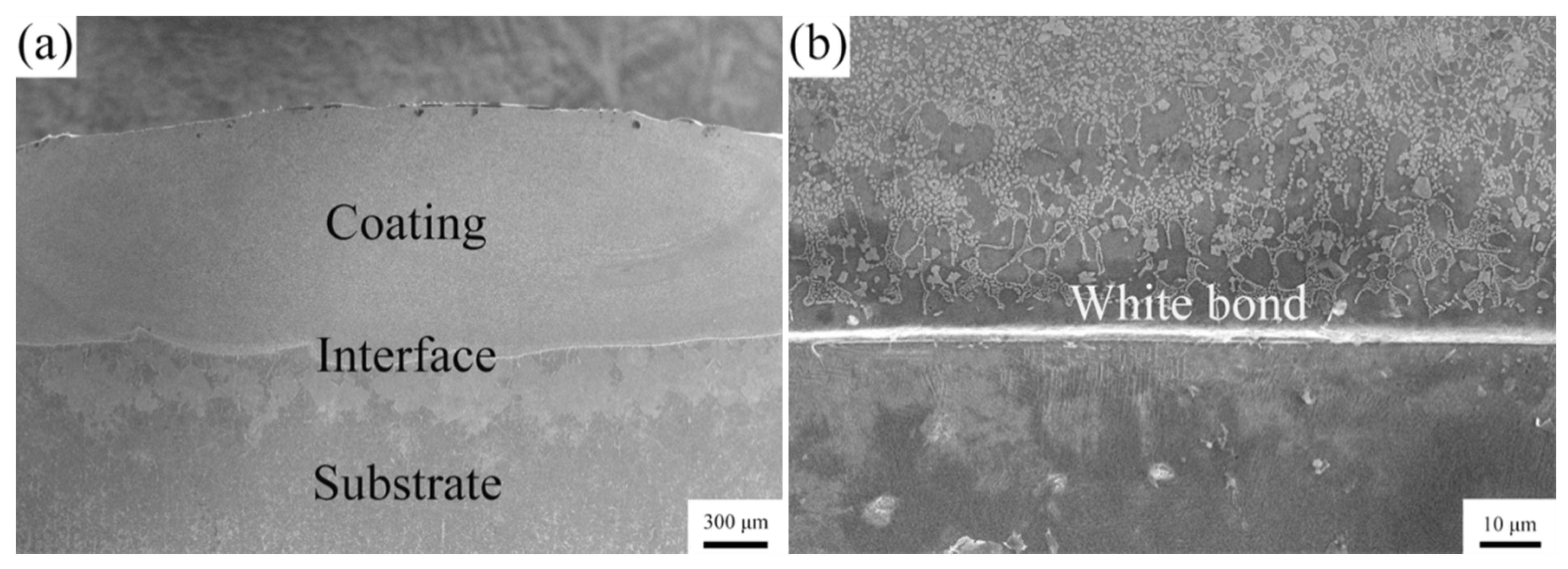
The cross-sectional macro-morphologies of Coating III are indicated in Figure 2. The cross-section of the sample can be clearly divided into two zones: the coating (about 1.1 mm in thickness) and the substrate. The compact coating presents a smooth surface and is free of cracks and pores (Figure 2a). A smooth wave-like interface shows a good metallurgical bond between the coating and the substrate. A highly magnified SEM image (Figure 2b) of the interface indicates that a white band with a thickness of about 3 μm is formed at the bottom of the coating, which is closely associated with the value of G/R (where G denotes the temperature gradient of the liquid phase and R indicates the solidification rate of the solid phase) during solidification. As reported in [38], the G value is greatest, but the R value is smallest at the interface, which means that the greatest G/R value is obtained at the interface. Therefore, the solidification will firstly occur on the substrate surface in the form of epitaxial growth without nucleation. In this condition, the latent heat of crystallization can only dissipate through the solid phase (substrate). The movement of the phase interface was essentially influenced by the heat transfer rate of the solid phase. The growth of the protruding parts into the liquid phase with an extremely high temperature will be seriously inhibited. However, the other parts with a higher supercooling degree own a comparatively fast growth rate. The solid–liquid interphase between the substrate and the molten pool will be maintained in a planar state during solidification, resulting in the formation of a white band at the interface.
Figure 3 reveals the microstructural evolution of the coatings. As shown in Figure 3a, Coating I is composed of equiaxed grains surrounded by the protruded network skeleton, in which some fine spherical particles with a diameter of about 1 μm are uniformly embedded (Figure 3b). The chemical compositions of the three zones marked in Figure 3b were analyzed by EDS (Table 2). Besides Al, Cr, Co, Ni and Ta involved in the cladding material, the other two elements, namely Fe and C, were found in the coatings. During cladding, the cladding material was melted under the radiation of a laser, besides which a thin layer of substrate was melted to participate in the formation of the molten pool. As a result, two elements of Fe and C rich in 45# steel were detected in the coatings. Moreover, polyvinyl alcohol painted on the substrate surface will suffer from decomposition and provide tiny amounts of C. The existence of C will have an important effect on the phase constituent of the coatings as analyzed in the latter. The equiaxed grains and the protruded network skeleton have very similar chemical compositions, which are composed of Fe (about 60–70 at.%) and the other metallic elements (Al, Co, Cr and Ni: about 30–40 at.%). Moreover, traces of C (about 1–2 at.%) were also detected. According to the dilution rate of the coatings, the content of C in the coatings can be approximately calculated as about 0.64 at.% in Coating I, 0.76 at.% in Coating II and 0.84 at.% in Coating III. Based on the XRD results, it can be reasonably concluded that they should correspond to the BCC solid solution. The network skeleton and the grain boundaries protrude from the microstructure when compared with the equiaxed grains after being subject to corrosion in the etchant (4 mL water, 6 mL HNO3 and 8 drops of HF), which could be attributed to the higher content of strong corrosion-resistant Cr in the former. The fine spherical particles are mainly C (about 40 at.%) and Fe (42 at.%), in which the other alloying elements (Al, Co, Cr and Ni) are also involved. They can be identified to be the carbide (MC). When Ta was introduced into AlCoCrNiTax (x = 0.5), the microstructure demonstrated a significant change. The equiaxed grains could also be observed; however, the continuous network skeleton was transformed into a discontinuous one which is composed of fine equiaxed or strip-like particles. Moreover, some comparatively coarse blocky particles were observed to be scattered in the microstructure (Figure 3c). An enlarged image composed of a SE image and a BSE image is shown in Figure 3d. The SE image clearly displays the morphological characteristics of two kinds of particles with different morphologies, and the BSE image demonstrates their difference in atomic number. The EDS result indicates that the equiaxed grains should be the BCC solid solution (Zone 4). The coarse blocky particles (Zone 6) are rich in C and Ta, which are determined as the secondary solid solution with TaC as the solvent and Al, Co, Cr, Ni and Fe as the solutes. The fine particles (Zone 5) distributed along the grain boundaries present similar atomic numbers compared to the coarse blocky particle and mainly consist of C, Ta and Fe. Combined with the XRD results, the two kinds of particles with different sizes can be categorized as TaC solid solution with some differences in the content of alloying elements. Previous studies also proved that secondary solid solutions with carbides (such as WC, TaC and TiC) as the solvent and some alloying elements (such as Ni, Co and Nb) as the solutes were synthesized by laser cladding [39,40,41]. Moreover, a portion of alloying elements (Al, Co, Cr, Ni and Fe) detected in TaC may originate from the matrix phase due to the diffusion effect of the electron beam in EDS analyses. When the electron beam is applied to a given surface zone (TaC), it will enter into the inner part of the zone and gradually diffuse to react with the pear-like zones with a larger volume. That means that the characteristic X-rays related to some alloying elements involved in the matrix phase may be excited and collected by EDS, resulting in those elements being detected in TaC. The evolution of the microstructure of laser-clad coatings is very difficult to reveal due to the rapid heating and cooling characteristic (about 106 °C·s−1 cooling rate). Therefore, the microstructural evolution of the laser-clad coatings is mainly described according to the resultant microstructure in present investigation [42,43,44]. During laser cladding, the elemental distribution is considerably inhomogeneous. TaC has a high melting point of about 3800 °C and will be preferentially precipitated in the molten pool. TaC will grow into coarse blocky particles in some zones rich in Ta. However, other fine TaC particles may grow at a comparatively low speed in the other zones poor in Ta. Fine TaC particles will be pushed to the grain boundaries along with the gradual growth of the BCC solid solution, resulting in the formation of a discontinuous skeleton. When x is further increased to 1.0, the coarse blocky TaC particles (Zone 9) can still be precipitated (Figure 3e,f). However, the equiaxed BCC solid solution grains are converted into flower-like grains, coupled with which its volume fraction is greatly reduced. Moreover, the fine TaC particles (Zone 5) in Coating II will be substituted for the high content of lamellar structures (Zone 8) in Coating III. The highly magnified images indicate that the lamellar particles are uniformly distributed within the BCC solid solution as the matrix (Figure 3g,h); therefore, the lamellar structures should belong to the eutectic structure. As shown in Table 2, the structure contains a lower Fe content than BCC and a lower Ta content than TaC, which further provides strong evidence for the formation of the eutectic structure. The formation of TaC with an extremely high hardness of about 1800 HV resulting from the introduction of Ta will produce a strong dispersion strengthening effect, which will contribute to the improvement in wear resistance.

3.3. Mechanical Properties

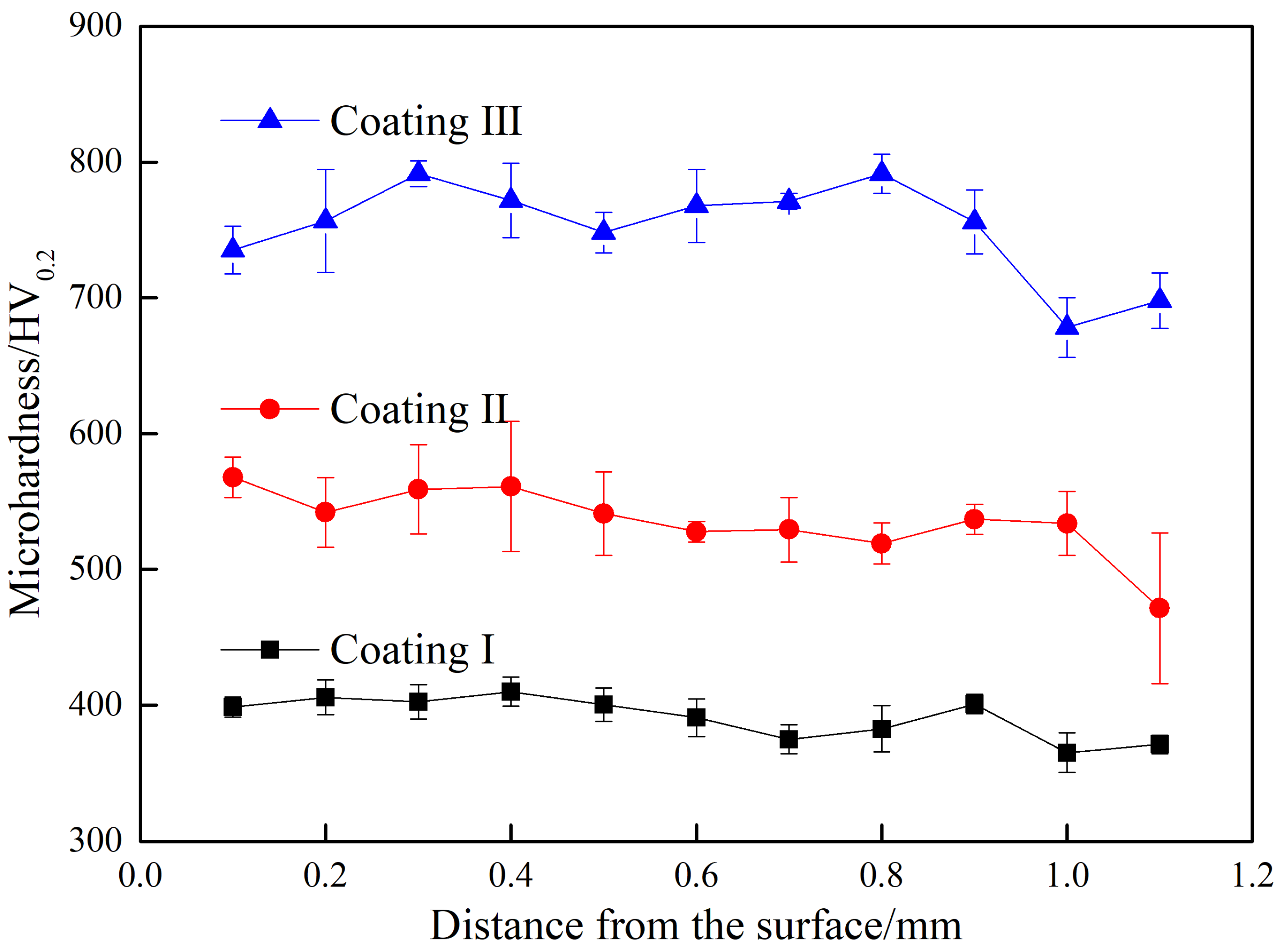
The change in the microhardness of the coatings (about 1.1 mm in thickness) with different contents of Ta is revealed in Figure 4. The microhardness distribution in all of the coatings fluctuates slightly, indicating that the microstructure is comparatively uniform. The average microhardness of Coating I is about 391 HV0.2, which is about two times of that of the substrate (200 HV0.2). This should be the combined result from the solid solution of BCC and dispersion of MC strengthening. When Ta is introduced into AlCoCrNiTax (x = 0.5), the average microhardness of the coating is improved by about 36.8% (535 HV0.2) in comparison with that of Coating I due to the significant difference in atomic radius between Ta and Fe and the formation of TaC with extremely high hardness of 1800 HV. Along with the increase in Ta content (x = 1.0), the average microhardness of the coating is further increased from 535 to 751 HV0.2, which should be attributed to the enhancement in TaC content.
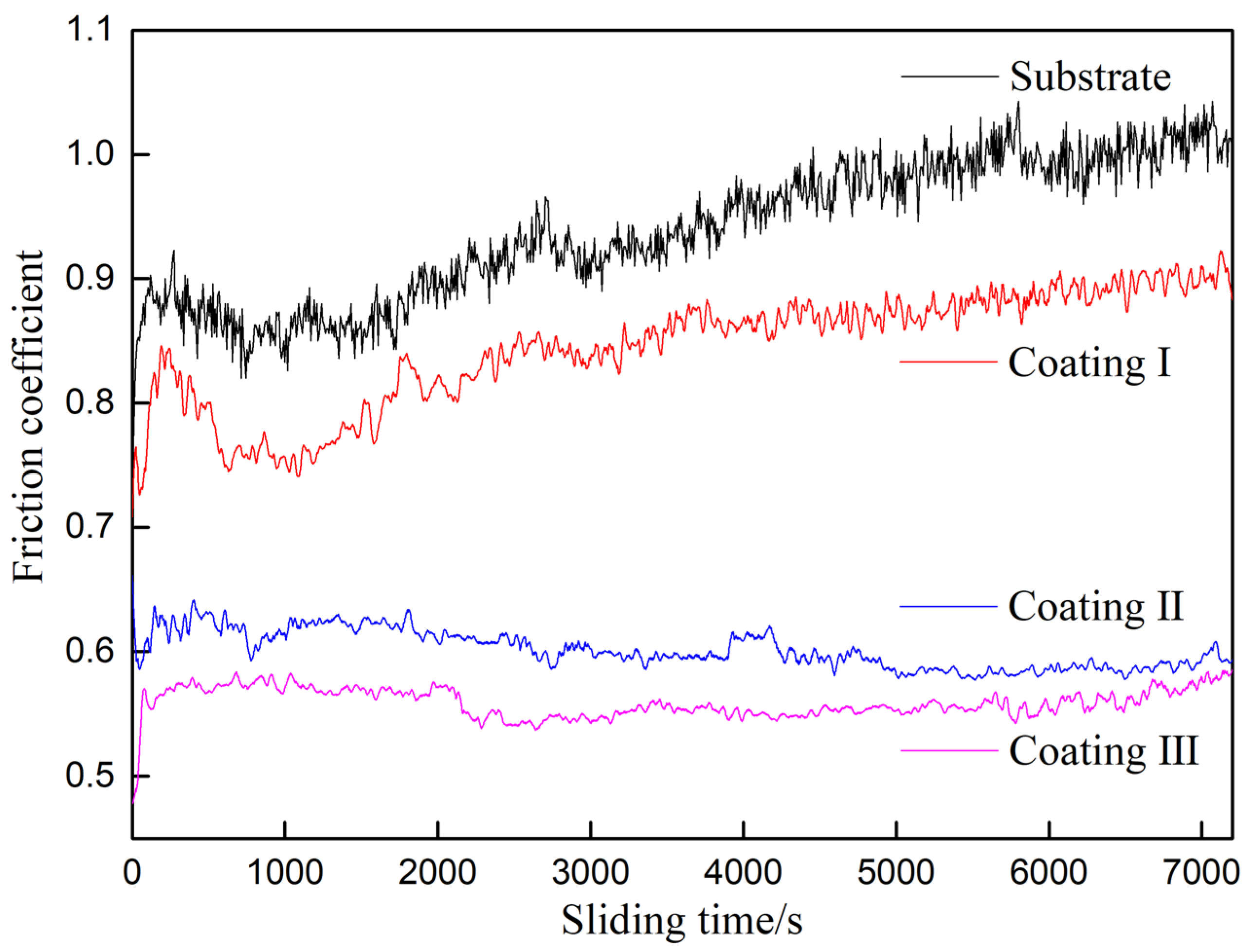
The change in friction coefficient (μ) of the samples with sliding time is indicated in Figure 5. The friction coefficient presents a drastic upward tendency in the initial short time of about 180 s and then enters a comparatively stable state. It is clear that the friction coefficient of the substrate suffers from the most drastic fluctuation with sliding time and the average value is also the highest among all of the samples (substrate: 0.94; Coating I: 0.84; Coating II: 0.60; Coating III: 0.56). After the substrate is modified by laser cladding AlCoCrNi, the change in friction coefficient of the coating with sliding time is very similar to that of the substrate. However, the average value is reduced by about 11%. When Ta is introduced to AlCoCrNi, the friction coefficient is very stable and only has a slight fluctuation during the whole sliding time. Moreover, the average value is greatly reduced by 29% (Coating II, x = 0.5) and 33% (Coating III, x = 1.0) when compared with that (Coating I) without Ta. The change is closely associated to the improvement in hardness of the samples resulting from the introduction of Ta. With respect to the substrate with a comparatively low hardness (200 HV0.2), the protrusions on the contact surface of the counterpart (about 2200 HV0.2) are easily impressed into the substrate surface under the applied compressive force (N). The protrusions deeply embedded into the substrate will suffer from great friction resistance (F) during sliding, resulting in the high friction coefficient obtained (μ = F/N). Moreover, sharp protrusions may produce micro-cutting, and blunt protrusions may cause serious plastic deformation of the substrate surface, which make the contact surface morphology become very complicated and unstable. Consequently, the friction coefficient presents a drastic change with the sliding time. When the substrate was covered with an AlCrCoNiFeC coating with a higher hardness (391 HV0.2), the coating demonstrated a stronger resistance to plastic deformation, implying that the embedded depth of those surface protrusions on the counterpart in the coating surface are correspondingly reduced. As a result, the average friction coefficient will be decreased to a certain extent. With the introduction of Ta into AlCrCoNiFeC, the hardness of the coatings is further enhanced due to the improved solid solution strengthening from the larger difference in atomic radius between Ta and Fe and the strong dispersion strengthening from new synthesized TaC particles. Along with the improvement to micro-cutting resistance, the friction coefficient is significantly reduced and fluctuates slightly along with the sliding time.
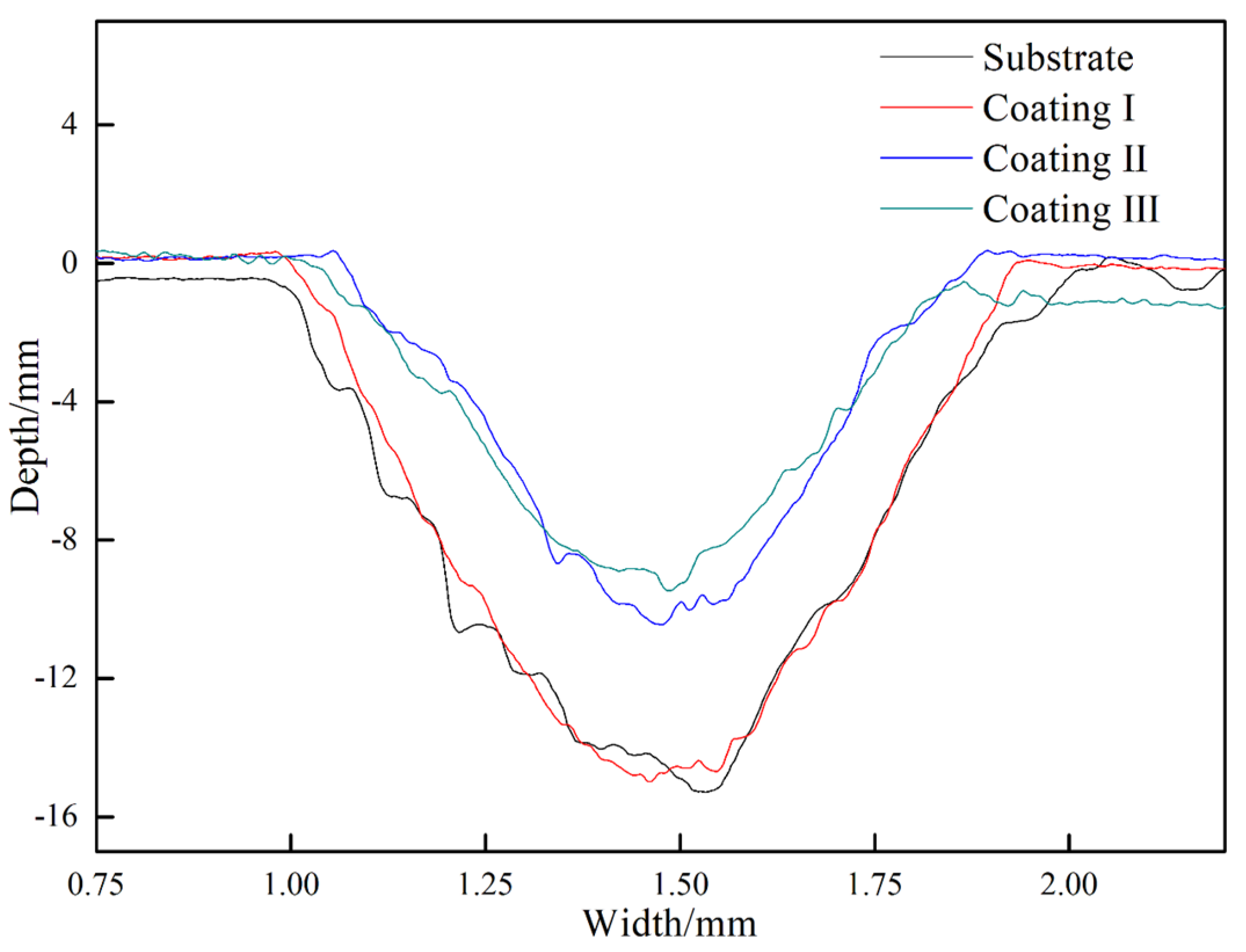
The profiles of worn tracks are indicted in Figure 6, and the corresponding wear rates were also calculated (Table 3). Coating I possesses a slightly lower wear rate when compared with that of the substrate owing to a small difference in hardness between them. However, the wear rates of the coatings containing Ta are drastically reduced by 43% (Coating II) and 52% (Coating III) when compared with that of the Coating I, which should be attributed to the improvement in resistance to micro-cutting as mentioned above. The wear rate of the coatings in air was also compared with those of other similar coatings prepared by laser cladding. As shown in Table 4, the wear rates of other HEA coatings are all higher than that of our work, which indicates that the addition of Ta plays a very positive role in improving the wear resistance of the HEA coatings.
Worn morphologies of the substrate and Coating III are shown in Figure 7. The worn surface of the substrate is wider and rougher than that of Coating III. A large number of furrows can be clearly observed on the substrate surface (Figure 7a), indicating that the substrate surface suffers from serious micro-cutting from the counterpart. Moreover, many grey blocky zones are interlaced with the black protruded zones on the substrate surface. A highly magnified image shows that the grey blocky zones are considerably rough and covered with innumerable fine particles (Figure 7b). The black zones are comparatively smooth; however, some cracks can be clearly recognized on them. EDS was applied to the analyzed chemical compositions related to the two zones (Table 5). The results clearly show that O is rich in the smooth black zones (62.51 at.%) but is poor in rough grey zones (17.64 at.%), indicating that the former undergoes serious oxidation and shields the substrate from micro-cutting as an oxidation layer. Some debris particles may adhere to the worn surface of the substrate during sliding. A portion of them may produce micro-cutting on the substrate surface, and the others may be embedded in the substrate surface. Many particles cluster together to form rough zones. With prolonging the time, the agglomerated particles are rolled into thin films and suffer from serious oxidation due to the produced friction heat (black zone). Oxidation layers with a higher hardness will greatly reduce the wear loss of the substrate. However, the cracks are easily subject to initiating and propagating in the oxidation layer, resulting in it gradually exfoliating from the substrate surface due to the loose binding between the thin layers and the substrate. Comparatively speaking, the surface of Coating III with the highest hardness was smooth, on which only a small quantity of slight scratches and narrow/shallow furrows were observed. This indicates that Coating III underwent weak micro-cutting. Moreover, the two zones corresponding to the grey zone and black zone can also be identified on the worn surface. The EDS results also confirm that the oxidized reactions occur on the surface of Coating III during sliding. It can be concluded that the wear mechanism of the two samples can be classified into a mixture of micro-cutting and oxidation. The oxidation reactions possibly occurring are as follows.
4 Fe + 3 O 2 = 2 Fe 2 O 3
4 Al + 3 O 2 = 2 Al 2 O 3
4 Cr + 3 O 2 = 2 Cr 2 O 3
2 Co + O 2 = 2 CoO
2 Ni + O 2 = 2 NiO
4 Ta + 5 O 2 = 2 Ta 2 O 5
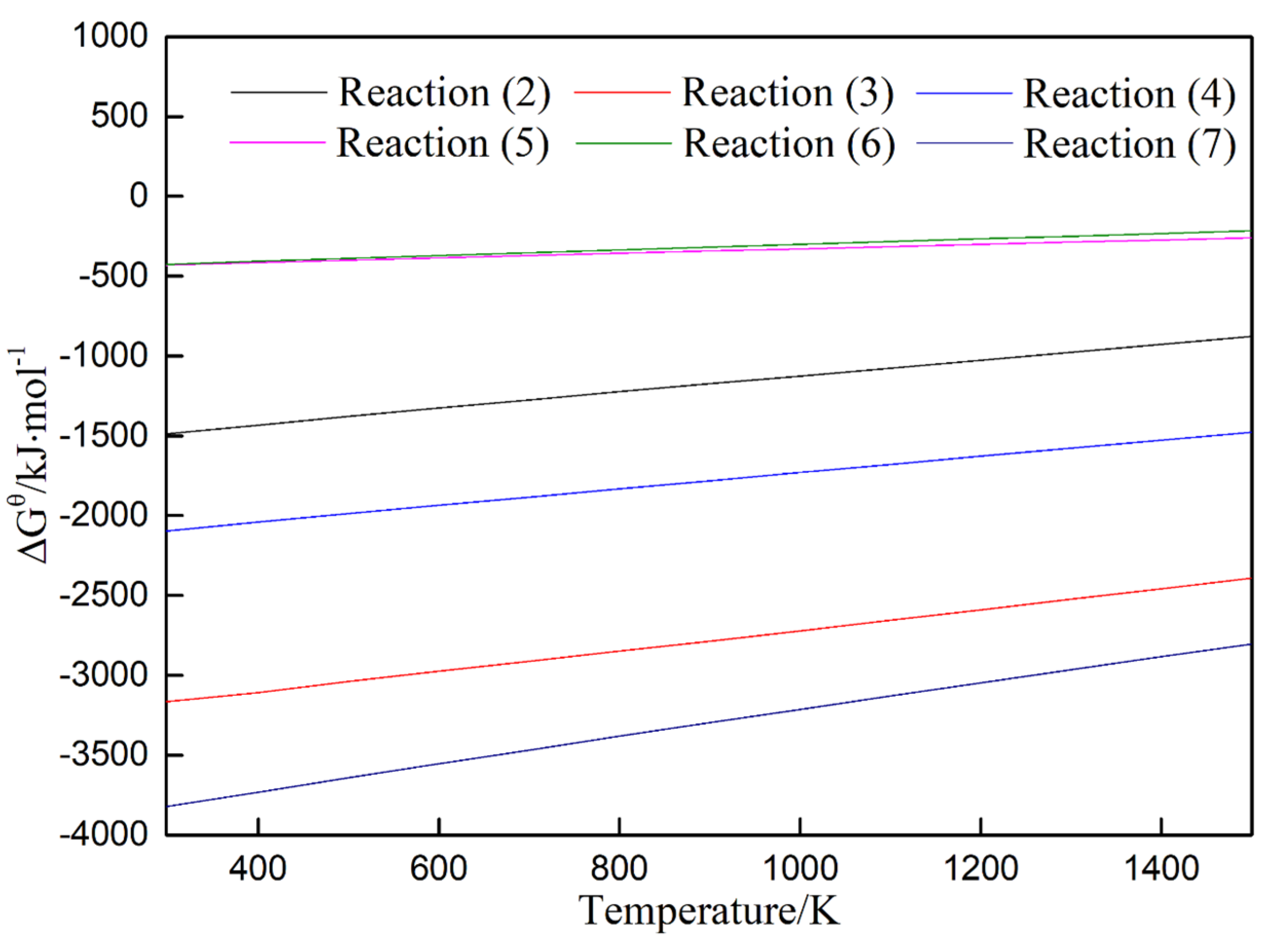
As shown in Figure 8, all of the abovementioned reactions can occur spontaneously due to their negative change in Gibbs free energy (ΔGθ), indicating that the corresponding oxides may be formed at the worn surface of Coating III during sliding.
The wear behaviors of the coatings were also investigated in a corrosive circumstance (3.5 wt.% NaCl). Figure 9 indicates the change in friction coefficient of the substrate and Coating III with the sliding time. The average friction coefficient presents an increasing tendency as follows: substrate (0.49) < Coating I (0.64) < Coatings II and III (0.71). The tendency is contrary to that observed in air, which could be attributed to the existence of a corrosion medium. In terms of the substrate, the debris particles may adhere to the worn surface or be embedded into the substrate during dry sliding friction, which greatly enhances the friction coefficient (0.94) due to the increase in friction force. However, those debris particles may be constantly washed away from the worn surface by the flowing medium through corrosion sliding friction, resulting in the worn surface being comparatively smooth. The average friction coefficient is correspondingly reduced owing to the decrease in friction force. Regarding the coatings, their friction coefficient has no significant differences; however, the value is comparatively higher than that obtained in air. The phenomenon is closely associated with the oxidation layer formed on the worn surfaces. The surfaces of the coatings are exposed to the air and are easily subject to oxidization due to the large amount of friction heat during the dry sliding friction. However, when the friction occurs in a corrosive medium, the generated friction heat can be rapidly dissipated from the worn surface by the corrosive medium, resulting in poor oxidation of the worn surface. Moreover, the content of oxygen in the corrosive medium is considerably lower than that in air, which further postpones the formation of an oxidation layer. Further to the abovementioned factors, the oxidation layer is easily destroyed due to O substituted for Cl- involved in the corrosive medium, causing the dissolution of the oxidation layer. This implies that a compact and intact oxidation film with a good lubrication effect is difficult to form on the worn surface in the corrosion friction circumstance, resulting in the slight increase in friction coefficient when compared with that in air.
Worn profiles of these coatings and the substrate are shown in Figure 10. Their wear rates present a downward tendency as follows: substrate (2.22 × 10⁻⁵ mm3·N−1·m−1) > Coating I (1.67 × 10⁻⁵ mm3·N−1·m−1) > Coating II (3.67 × 10⁻⁶ mm3·N−1·m−1) > Coating III (3.30 × 10⁻⁶ mm3·N−1·m−1). The tendency is also consistent with that obtained in dry sliding, showing that the wear-corrosive resistance can be improved by laser cladding an AlCrCoNiFeCTa coating on 45# steel. By carefully comparing the wear rates in air and in a corrosive circumstance, it can be seen that the corrosive circumstance can accelerate wear of the substrate and Coating I due to the debris particles resulting from the micro-cutting rapidly being removed from their worn surfaces. However, the wear rates of the two coatings with Ta are reduced to a certain extent when compared with those in air, which can be mainly attributed to the combination of their strong resistance to micro-cutting and poor oxidation. Therefore, the wear mechanism of the samples in the corrosive friction circumstance could be confirmed as micro-cutting and slight oxidation. The results indicate that the introduction of Ta into AlCrCoNiFeC can improve wear resistance not only in air but also in a corrosive medium. The wear rates of the coatings prepared in our work in 3.5 wt.% NaCl solution were also compared with those reported in the relative references. As shown in Table 6, even in a harsh corrosive environment, the coating prepared in our work still demonstrates the lowest wear rate, which reveals that the addition of Ta is beneficial to the promotion of the wear resistance in a corrosive environment of the HEA coatings.
Worn surfaces of the samples further provide strong evidence for the above analyses. As shown in Figure 11, the substrate suffered from serious cutting, evidenced by the large number of furrows observed. Some debris particles are loosely dispersed on the worn surface, which are not rolled into the highly oxidized layer tightly adhering to the worn surface like those in air. The worn surface of Coating III is very smooth and almost free of adhering debris particles and furrows. The microstructure of the coating can even be clearly identified on the worn surface, indicating that the oxidation layer is not almost formed. The EDS results also show that the content of O is far lower than that on the worn surface obtained in the dry friction condition (Table 5).

4. Conclusions

(1) Laser-clad AlCrCoNiFeCTax (x = 0, 0.5 and 1.0) HEA coatings were successfully fabricated on 45# steel. The coatings were composed of two phases in terms of BCC and carbide. As x was increased from 0 to 0.5 and, finally, to 1.0, the microstructure was transformed from BCC + fine MC (M = Al, Cr, Co and Ni) particles into BCC + coarse/fine TaC particles and, finally, into BCC + coarse TaC particles + lamellar eutectic (BCC + TaC). Moreover, the volume fraction of BCC presented a downward tendency accompanied with an increase in that of carbide.
(2) The average microhardness of the coatings was higher than that of the substrate (200 HV0.2) and demonstrated an upward tendency (391 HV0.2 for x = 0, 535 HV0.2 for x = 0.5 and 751 HV0.2 for x = 1.0).
(3) The wear rates of the coatings were gradually reduced with the increase in x (7.48 × 10⁻⁶ mm3·N−1·m−1 for x = 0; 4.44 × 10⁻⁶ mm3·N−1·m−1 for x = 0.5 and 3.73 × 10⁻⁶ mm3·N−1·m−1 for x = 1.0) in air friction, which were all lower than that of the substrate (7.62 × 10⁻⁶ mm3·N−1·m−1). The wear resistance of the coatings and the substrate in NaCl solution also showed the same regularity (1.67 × 105 mm3·N−1·m−1 for x = 0; 3.67 × 10⁻⁶ mm3·N−1·m−1 for x = 0.5; 3.30 × 10⁻⁶ mm3·N−1·m−1 for x = 1.0 and 2.22 × 105 mm3·N−1·m−1 for the substrate). It is worth noting that the coating with x = 0 and the substrate showed higher wear rates in NaCl solution compared with them in air; however the contrary change was indicated for the coatings with x = 0.5 and 1.0.
(4) The AlCrCoNiFeCTa demonstrated the outstanding wear resistance both in air and in NaCl solution.

Author Contributions

Investigation, P.Z.; Methodology, J.L. and R.L.; Experiment, P.Z. and R.L.; Formal analysis, P.Z. and R.L.; Resources, J.L.; Supervision, J.L.; Validation. R.L., B.Y. and M.X.; Software, B.Y. and X.L.; Writing—original draft preparation, P.Z.; Writing—review and editing, M.X., X.L. and Y.Z. All authors have read and agreed to the published version of the manuscript.

Funding

This research was funded by the National Natural Science Foundation of China, grant number 51471105, and the Natural Science Foundation of Shanghai, grant number 20ZR1422200.

Institutional Review Board Statement

Not applicable.

Informed Consent Statement

Not applicable.

Data Availability Statement

Data sharing not applicable.

Acknowledgments

This work was financially supported by the National Natural Science Foundation of China (51471105) and the Natural Science Foundation of Shanghai (20ZR1422200).

Conflicts of Interest

We declare that we do not have any commercial or associative interest that represents a conflict of interest in connection with the work submitted.

References

  1. Li, H.X.; Lu, Z.C.; Wang, S.L.; Wu, Y.; Lu, Z.P. Fe-based bulk metallic glasses: Glass formation, fabrication, properties and applications. Prog. Mater. Sci. 2019, 103, 235–318. [Google Scholar] [CrossRef]
  2. Liu, H.X.; Xu, Q.; Wang, C.Q.; Zhang, X.W. Corrosion and wear behavior of Ni60CuMoW coatings fabricated by combination of laser cladding and mechanical vibration processing. J. Alloy. Compd. 2015, 621, 357–363. [Google Scholar] [CrossRef]
  3. Shang, F.M.; Chen, S.Y.; Zhang, C.Y.; Liang, J.; Liu, C.S.; Wang, M. The effect of Si and B on formability and wear resistance of preset-powder laser cladding W10V5Co4 alloy steel coating. Opt. Laser Technol. 2021, 134, 106590. [Google Scholar] [CrossRef]
  4. Panda, J.N.; Wong, B.C.; Medvedovski, E.; Egberts, P. Enhancement of tribo-corrosion performance of carbon steel through boronizing and BN-based coatings. Tribo. Int. 2021, 153, 106666. [Google Scholar] [CrossRef]
  5. Kossman, S.; Coelho, L.B.; Mejias, A.; Montagne, A.; Gorp, A.V.; Coorevits, T.; Touzin, M.; Poorteman, M.; Olivier, M.G.; Iost, A.; et al. Impact of industrially applied surface finishing processes on tribocorrosion performance of 316L stainless steel. Wear 2020, 456–457, 203341. [Google Scholar] [CrossRef]
  6. Zheng, K.; Wang, Y.R.; Wang, R.Y.; Wang, Y.L.; Cheng, F.; Ma, Y.; Hei, H.J.; Gao, J.; Zhou, B.; Wang, Y.S.; et al. Microstructure, oxidation behavior and adhesion of a CoNiCrAlTaY coating deposited on a high Nb–TiAl alloy by plasma surface metallizing technique. Vacuum 2020, 179, 109494. [Google Scholar] [CrossRef]
  7. Attard, B.; Leyland, A.; Matthews, A.; Gutmanas, E.Y.; Gotman, I.; Cassar, G. Improving the surface characteristics of Ti-6Al-4V and Timetal 834 using PIRAC nitriding treatments. Surf. Coat. Technol. 2018, 339, 208–223. [Google Scholar] [CrossRef]
  8. Li, G.M.; Liang, Y.L.; Yin, C.H.; Sun, H.; Zhu, Z.L. Study of M50NiL steel under carburizing and nitriding duplex treatment. Surf. Coat. Technol. 2019, 375, 132–142. [Google Scholar] [CrossRef]
  9. Zhang, J.; Xue, Q.; Li, S.X.; Qin, Z. Microstructure, corrosion and tribological properties of Ti(CN) multilayer coatings on 35CrMo steel by CVD. Rare Met. 2020, 39, 1314–1320. [Google Scholar] [CrossRef]
  10. Dong, C.M.; Cui, Q.F.; Gao, X.M.; Jiang, D.; Fu, Y.L.; Wang, D.S.; Weng, L.J.; Hu, M.; Sun, J.Y. Tribological property of MoS2-Cr3O4 nanocomposite films prepared by PVD and liquid phase synthesis. Surf. Coat. Technol. 2020, 403, 126382. [Google Scholar] [CrossRef]
  11. Wang, Y.W.; Wang, X.Y.; Wang, X.L.; Yang, Y.; Cui, Y.H.; Ma, Y.D.; Sun, W.W. Microstructure and properties of in-situ composite coatings prepared by plasma spraying MoO3–Al composite powders. Ceram. Int. 2021, 47, 1109–1120. [Google Scholar] [CrossRef]
  12. Sassi, W.; Boubaker, H.; Bahar, S.; Othman, M.; Ghorbal, A.; Zrelli, R.; Hihn, J.-Y. A challenge to succeed the electroplating of nanocomposite Ni–Cr alloy onto porous substrate under ultrasonic waves and from a continuous flow titanium nanofluids. J. Alloy. Compd. 2020, 828, 154437. [Google Scholar] [CrossRef]
  13. Ding, Z.L.; Zhou, Q.; Wang, Y.; Ding, Z.Y.; Tang, Y.H.; He, Q.G. Microstructure and properties of monolayer, bilayer and multilayer Ta2O5-based coatings on biomedical Ti-6Al-4V alloy by magnetron sputtering. Ceram. Int. 2021, 47, 1133–1144. [Google Scholar] [CrossRef]
  14. Katinas, E.; Jankauskas, V.; Kazak, N.; Michailov, V. Improving Abrasive Wear Resistance for Steel Hardox 400 by Electro-Spark Deposition. J. Frict. Wear 2019, 40, 100–106. [Google Scholar] [CrossRef]
  15. Guan, Q.F.; Zhang, S.H.; Zheng, H.H.; Li, C.; Zhang, C.L.; Lv, P. Cr surface alloying of 45# steel by high-current pulsed electron beam treatment. J. Jilin Univ. 2018, 48, 1161–1168. [Google Scholar]
  16. Gromov, V.E.; Gorbunov, S.V.; Ivanov, Y.F.; Vorobiev, S.V.; Konovalov, S.V. Formation of surface gradient structural-phase states under electron-beam treatment of stainless steel. J. Surf. Invest. 2011, 5, 974–978. [Google Scholar] [CrossRef]
  17. Zhang, K.; Zou, J.; Grosdidier, T.; Dong, C. Formation and evolution of craters in carbon steels during low-energy high-current pulsed electron-beam treatment. J. Vac. Sci. Technol. A Vac. Surf. Film. 2009, 27, 1217–1226. [Google Scholar] [CrossRef]
  18. Siddiqui, A.A.; Dubey, A.K. Recent trends in laser cladding and surface alloying. Opt. Laser Technol. 2021, 134, 106619. [Google Scholar] [CrossRef]
  19. Li, N.; Huang, S.; Zhang, G.D.; Qin, R.Y.; Liu, W.; Xiong, H.P.; Shi, G.Q.; Blackburn, J. Progress in additive manufacturing on new materials: A review. J. Mater. Sci. Technol. 2019, 35, 242–269. [Google Scholar] [CrossRef]
  20. Yeh, J.W.; Chen, S.K.; Lin, S.J.; Gan, J.Y.; Chin, T.S.; Shun, T.T.; Tsau, C.H.; Chang, S.Y. Nanostructured high-entropy alloys with multiple principal elements: Novel alloy design concepts and outcomes. Adv. Eng. Mater. 2004, 6, 299–303. [Google Scholar] [CrossRef]
  21. Ding, Q.Q.; Zhang, Y.; Chen, X.; Fu, X.Q.; Chen, D.K.; Chen, S.J.; Gu, L.; Wei, F.; Bei, H.B.; Gao, Y.F.; et al. Tuning element distribution, structure and properties by composition in high-entropy alloys. Nature 2019, 574, 223–227. [Google Scholar] [CrossRef]
  22. Juan, Y.F.; Li, J.; Jiang, Y.Q.; Jia, W.L.; Lu, Z.J. Modified criterions for phase prediction in the multi-component laser-clad coatings and investigations into microstructural evolution/wear resistance of FeCrCoNiAlMox laser-clad coatings. Appl. Surf. Sci. 2019, 465, 700–714. [Google Scholar] [CrossRef]
  23. Qiu, X.W. Microstructure and mechanical properties of CoCrFeNiMo high-entropy alloy coatings. J. Mater. Res. Technol. 2020, 9, 5127–5133. [Google Scholar] [CrossRef]
  24. Liang, H.; Miao, J.W.; Gao, B.Y.; Deng, D.W.; Wang, T.M.; Lu, Y.P.; Cao, Z.Q.; Jiang, H.; Li, T.J.; Kang, H.J. Microstructure and tribological properties of AlCrFe2Ni2W0.2Mo0.75 high-entropy alloy coating prepared by laser cladding in seawater, NaCl solution and deionized water. Surf. Coat. Technol. 2020, 400, 126214. [Google Scholar] [CrossRef]
  25. Wen, X.; Cui, X.F.; Jin, G.; Zhang, X.R.; Zhang, Y.; Zhang, D.; Fang, Y.C. Design and characterization of FeCrCoAlMn0.5Mo0.1 high-entropy alloy coating by ultrasonic assisted laser cladding. J. Alloy. Compd. 2020, 835, 155449. [Google Scholar] [CrossRef]
  26. Zhang, Y.; Han, T.F.; Xiao, M.; Shen, Y.F. Effect of process parameters on the microstructure and properties of laser-clad FeNiCoCrTi0.5 high-entropy alloy coating. Int. J. Min. Met. Mater. 2020, 27, 630–639. [Google Scholar] [CrossRef]
  27. Zhang, Y.; Han, T.F.; Xiao, M.; Shen, Y.F. Effect of Nb content on microstructure and properties of laser cladding FeNiCoCrTi0.5Nbx high-entropy alloy coating. Optik 2019, 198, 163316. [Google Scholar] [CrossRef]
  28. Chen, W.; Dejun, K. Effects of Al mass fraction on corrosive wear and electrochemical corrosion of laser cladded AlFeCoCr amorphous coating in 3.5 wt% NaCl solution. Mater. Res. Express 2019, 6, 076552. [Google Scholar] [CrossRef]
  29. Liu, H.; Li, X.J.; Liu, J.; Gao, W.P.; Du, X.T.; Hao, J.B. Microstructural evolution and properties of dual-layer CoCrFeMnTi0.2 high-entropy alloy coating fabricated by laser cladding. Opt. Laser Technol. 2021, 134, 106646. [Google Scholar] [CrossRef]
  30. Hu, L.F.; Li, J.; Tao, Y.F.; Lv, Y.H. Corrosion behaviors of TiNi/Ti2Ni matrix coatings in the environment rich in Cl ions. Surf. Coatings Technol. 2017, 311, 295–306. [Google Scholar] [CrossRef]
  31. Yan, L. Production Practice of Converter Continuous Casting for 45~# Steel. Anhui Metal. 2001, 1, 19–23. [Google Scholar]
  32. Wüstholz, T.; Reinhardt, H.W. Deformation behaviour of self-compacting concrete under tensile loading. Mater. Struct. 2007, 40, 965–977. [Google Scholar]
  33. Gao, K.; Guo, J.Z.; Qin, X.P. Kinetics modeling for austenite transformation inAISI 1045 steel during rapid heating under high frequency electromagnetic field. J. Cent. South Univ. 2020, 27, 1543–1556. [Google Scholar] [CrossRef]
  34. Archard, J.F. Contact and Rubbing of Flat Surfaces. J. Appl. Phys. 1953, 24, 981–988. [Google Scholar] [CrossRef]
  35. Lv, Y.H.; Li, J.; Tao, Y.F.; Hu, L.F. High-temperature wear and oxidation behaviors of TiNi/Ti2Ni matrix composite coatings with TaC addition prepared on Ti6Al4V by laser cladding. Appl. Surf. Sci. 2017, 402, 478–494. [Google Scholar] [CrossRef]
  36. Ren, P.; Wen, M.; Zhang, K.; Du, S.X.; Zhang, Y.D.; Chen, J.H.; Zheng, W.T. Self-assembly of TaC@Ta core-shell-like nanocomposite film via solid-state dewetting: Toward superior wear and corrosion resistance. Acta Mater. 2018, 160, 72–84. [Google Scholar] [CrossRef]
  37. Li, J.; Zhang, H.Y.; Li, W.G.; Zhang, G.J. Microstructure and properties of in situ synthesized TiB2+WC reinforced composite coatings. Rare Met. 2008, 27, 451–456. [Google Scholar] [CrossRef]
  38. Yang, S.; Zhong, M.L.; Liu, W.J. TiC particulate composite coating produced in situ by laser cladding. Mater. Sci. Eng. A 2003, 343, 57–62. [Google Scholar] [CrossRef]
  39. Zhao, S.; Yang, L.; Huang, Y.; Xu, S. A novel method to fabricate Ni/WC composite coatings by laser wire deposition: Processing characteristics, microstructural evolution and mechanical properties under different wire transfer modes. Addit. Manuf. 2021, 38, 101738. [Google Scholar] [CrossRef]
  40. Li, Z.Y.; Yan, H.; Zhang, P.L.; Guo, J.L.; Yu, Z.S.; Ringsberg, J.W. Improving surface resistance to wear and corrosion of nickel-aluminum bronze by laser-clad TaC/Co-based alloy composite coatings. Surf. Coat. Technol. 2021, 405, 126592. [Google Scholar] [CrossRef]
  41. Zhang, M.Y.; Li, M.; Chi, J.; Wang, S.F.; Fang, M.; Zhou, C.; Liang, B.; Xue, J.X. In-situ (Ti,Nb)C reinforced Ni-based coatings: New insights into microstructure evolution, enhanced phase configuration behavior and tribological properties. Ceram. Int. 2020, 46, 14161–14172. [Google Scholar] [CrossRef]
  42. Kuang, S.H.; Zhou, F.; Zheng, S.S.; Liu, Q.B. Annealing-induced microstructure and properties evolution of refractory MoFeCrTiWAlNb3 eutectic high-entropy alloy coating by laser cladding. Intermetallics 2021, 129, 107039. [Google Scholar] [CrossRef]
  43. Wen, X.; Cui, X.F.; Jin, G.; Liu, Y.F.; Zhang, Y.; Fang, Y.C. In-situ synthesis of nano-lamellar Ni1.5CrCoFe0.5Mo0.1Nbx eutectic high-entropy alloy coatings by laser cladding: Alloy design and microstructure evolution. Surf. Coat. Technol. 2021, 405, 126728. [Google Scholar] [CrossRef]
  44. Muvvala, G.; Mullick, S.; Nath, A.K. Development of process maps based on molten pool thermal history during laser cladding of Inconel 718/TiC metal matrix composite coatings. Surf. Coat. Technol. 2020, 399, 126100. [Google Scholar] [CrossRef]
  45. Miao, J.W.; Liang, H.; Zhang, A.J.; He, J.Y.; Meng, J.H.; Lu, Y.P. Tribological behavior of an AlCoCrFeNi2.1 eutectic high entropy alloy sliding against different counterfaces. Tribol. Int. 2021, 153, 106599. [Google Scholar] [CrossRef]
  46. Liu, H.; Sun, S.F.; Zhang, T.; Zhang, G.Z.; Yang, H.F.; Hao, J.B. Effect of Si addition on microstructure and wear behavior of AlCoCrFeNi high-entropy alloy coatings prepared by laser cladding. Surf. Coat. Technol. 2021, 405, 126522. [Google Scholar] [CrossRef]
  47. Moravcikova-Gouvea, L.; Moravcik, I.; Omasta, M.; Veselý, J.; Cizek, J.; Minárik, P.; Cupera, J.; Záděra, A.; Jan, V.; Dlouhy, I. High-strength Al0.2Co1.5CrFeNi1.5Ti high-entropy alloy produced by powder metallurgy and casting: A comparison of microstructures, mechanical and tribological properties. Mater. Charact. 2020, 159, 110046. [Google Scholar] [CrossRef]
  48. Li, Y.Z.; Shi, Y. Microhardness, wear resistance, and corrosion resistance of AlxCrFeCoNiCu high-entropy alloy coatings on aluminum by laser cladding. Opt. Laser Technol. 2021, 134, 106632. [Google Scholar] [CrossRef]
  49. Xiao, J.K.; Wu, Y.Q.; Chen, J.; Zhang, C. Microstructure and tribological properties of plasma sprayed FeCoNiCrSiAlx high entropy alloy coatings. Wear 2020, 448–449, 203209. [Google Scholar] [CrossRef]
  50. Xiao, J.K.; Tan, H.; Chen, J.; Martini, A.; Zhang, C. Effect of carbon content on microstructure, hardness and wear resistance of CoCrFeMnNiCx high-entropy alloys. J. Alloy. Compd. 2020, 847, 156533. [Google Scholar] [CrossRef]
  51. Ayyagari, A.; Barthelemy, C.; Gwalani, B.; Banerjee, R.; Scharf, T.W.; Mukherjee, S. Reciprocating sliding wear behavior of high entropy alloys in dry and marine environments. Mater. Chem. Phys. 2018, 210, 162–169. [Google Scholar] [CrossRef]
  52. Zhao, D.C.; Yamaguchi, T.; Shu, J.F.; Tokunaga, T.; Danjo, T. Rapid fabrication of the continuous AlFeCrCoNi high entropy alloy coating on aluminum alloy by resistance seam welding. Appl. Surf. Sci. 2020, 517, 145980. [Google Scholar] [CrossRef]
  53. Yu, Y.; Xu, N.N.; Zhu, S.Y.; Qiao, Z.H.; Zhang, J.B.; Yang, J.; Liu, W.M. A novel Cu-doped high entropy alloy with excellent comprehensive performances for marine application. J. Mater. Sci. Technol. 2021, 69, 48–59. [Google Scholar] [CrossRef]
Figure 1. X-ray diffraction patterns of the coatings.
Coatings 11 00358 g001
Figure 2. (a) The cross-sectional macro-morphology of Coating III; (b) the interface between Coating III and the substrate.
Coatings 11 00358 g002
Figure 3. (a,b) SE (Secondary electron) images of Coating I; (c) SE image of Coating II; (d) SE image (left) and BSE (Back-scattered electrons) image (right) of Coating II; (eg) SE images of Coating III; (h) BSE image of Coating III.
Coatings 11 00358 g003
Figure 4. The microhardness distribution along the cross-section of the coatings.
Coatings 11 00358 g004
Figure 5. The relationship between friction coefficient and sliding time of the substrate and the coatings subject to friction in air.
Coatings 11 00358 g005
Figure 6. Worn profiles of the substrate and the coatings subject to friction in air.
Coatings 11 00358 g006
Figure 7. Wear tracks of the substrate (a,b) and Coating III (c,d) subject to friction in air.
Coatings 11 00358 g007
Figure 8. Changes in standard Gibbs free energy (ΔGθ) of the reactions (2)–(7) with the tempera–ture.
Coatings 11 00358 g008
Figure 9. The relationship between friction coefficient and sliding time of the substrate and the coatings subject to friction in 3.5 wt.% NaCl solution.
Coatings 11 00358 g009
Figure 10. Worn profiles of the substrate and the coatings subject to friction in 3.5 wt.% NaCl solu–tion.
Coatings 11 00358 g010
Figure 11. Wear tracks of the substrate (a,b) and Coating III (c,d) subject to friction in 3.5 wt.% NaCl solution.
Coatings 11 00358 g011
Table 1. Comparison of d value related to BCC among the coatings.
Crystal FaceTheoretical d Value in JCPDS Card: NO.03-065-4899/nmExperimental d Value/nm
Coating ICoating IICoating III
(110)2.027282.018942.039482.04060
(200)1.433501.399241.441721.44290
(211)1.170451.168091.175141.17840
(220)1.013641.01141.017531.01888
Table 2. Chemical compositions of marked zones shown in Figure 3.
CoatingZonesElements (at.%)
CAlCrCoNiFeTa
Coating I11.006.006.939.576.8569.630
21.587.9011.3011.316.7461.160
339.023.915.436.003.8841.750
Coating II42.325.689.3812.647.2860.262.44
550.672.543.775.622.5017.8217.08
651.946.161.432.200.755.5531.97
Coating III71.569.709.2511.428.6256.932.51
838.663.945.637.415.0831.407.89
967.51.411.360.5504.9824.19
Table 3. Wear volumes and wear rates of the samples subject to friction in air and 3.5 wt.% NaCl solution.
Friction CircumstanceSampleWear Volume/mm3Wear Rate/mm3·N−1·m−1
AirSubstrate0.02477.62 × 10−6
Coating I0.02427.48 × 10−6
Coating II0.01444.44 × 10−6
Coating III0.01213.73 × 10−6
NaCl solutionSubstrate0.07182.22 × 10−5
Coating I0.05411.67 × 10−5
Coating II0.01193.67 × 10−6
Coating III0.01073.30 × 10−6
Table 4. Comparison of wear rates of high-entropy alloy (HEA) coatings in air between our works and the relative references.
CoatingsEnvironmentWear Rate/mm3·N−1·m−1Refs.
AlCoCrFeNi2.1Air3.27 × 10−4[45]
AlCoCrFeNiSi0.5Air1.48 × 10−4[46]
Al0.2Co1.5CrFeNi1.5TiAir2.50 × 10−5[47]
AlCrFeCoNiCuAir9.74 × 10−6[48]
FeCoNiCrSiAlAir6.70 × 10−6[49]
CoCrFeMnNiC0.6Air4.70 × 10−6[50]
AlCrCoNiFeCTaAir3.73×10−6Our work
Table 5. Chemical compositions of marked zones shown in Figure 7 and Figure 11.
Friction CircumstanceSamplesZonesElements (at.%)
COFeAlCrCoNiTa
AirSubstrate113.9017.6468.46-----
29.4262.5128.07-----
Coating III317.177.4057.233.324.432.823.114.52
412.4553.4027.041.751.761.522.070
NaCl solutionSubstrate525.3813.7360.09-----
Coating III637.6611.0630.462.994.333.844.405.26
Table 6. Comparison of wear rates of high-entropy alloy coatings in corrosive solutions between our work and the relative references.
CoatingsEnvironmentWear Rate/mm3·N−1·m−1Refs.
Al0.1CoCrFeNiSeawater4.40 × 10−4[51]
AlFeCrCoNiNaCl4.40 × 10−5[52]
AlCrFe2Ni2W0.2Mo0.75NaCl1.74 × 10−5[24]
AlCoCrFeNiCu0.5Seawater8.8 × 10−6[53]
AlCrCoNiFeCTaNaCl3.73 × 10−6Our work
Publisher’s Note: MDPI stays neutral with regard to jurisdictional claims in published maps and institutional affiliations.