Article

Microstructure and Mechanical Properties of ZrN, ZrCN and ZrC Coatings Grown by Chemical Vapor Deposition

1
Christian Doppler Laboratory for Advanced Coated Cutting Tools at the Department of Materials Science, Montanuniversität Leoben, 8700 Leoben, Austria
2
Department of Materials Science, Montanuniversität Leoben, 8700 Leoben, Austria
3
Ceratizit Austria GmbH, 6600 Reutte, Austria
*
Author to whom correspondence should be addressed.
Coatings 2021, 11(5), 491; https://doi.org/10.3390/coatings11050491
Submission received: 25 March 2021 / Revised: 13 April 2021 / Accepted: 20 April 2021 / Published: 22 April 2021
(This article belongs to the Special Issue Chemical Vapor Deposition (CVD) Coatings)

Abstract

:
As the demands for wear-resistant coatings in the cutting industry are constantly rising, new materials that have the potential to exhibit enhanced coating properties are continuously explored. Chemical vapor deposited (CVD) Zr(N,C) is a promising alternative to the well-established and thoroughly investigated Ti(C,N) coating system, owing to its advantageous mechanical and thermal properties. Thus, within this work, CVD ZrN, ZrCN and ZrC coatings were deposited at 1000 °C, and subsequently their microstructure and mechanical properties were investigated in detail. Scanning electron microscopy, electron backscatter diffraction and X-ray diffraction experiments revealed that all coatings exhibited a columnar structure and a fiber texture, where ZrN and ZrCN displayed a <100> preferred orientation in growth direction and ZrC showed a <110> texture. Tensile residual stresses that arise due to a mismatch in the coefficient of thermal expansion between the cemented carbide substrate and the coating material decreased with the addition of C to the coatings. No stress relaxation through thermal crack formation was observed in the coatings. The highest hardness was determined for the ZrC coating with 28.1 ± 1.0 GPa and the lowest for the ZrN coating with 22.1 ± 0.9 GPa. Addition of C to the ZrN coating increased the hardness to 26.1 ± 1.6 GPa, which can be explained by a more covalent bonding character, as well as by solid solution strengthening. The ZrCN coating exhibited the highest Young’s modulus, followed by the ZrC and ZrN coatings, which can be attributed to differences in their electronic band structure.

1. Introduction

Protective hard coatings for cemented carbide cutting tools are frequently used to improve the cutting performance [1]. While chemically vapor deposited (CVD) TiN, TiCN and TiC coatings have been intensively investigated and widely used for several decades [2,3,4,5,6,7,8], literature on alternative CVD transition metal nitride, carbonitride and carbide coatings is limited. However, some reports suggest advantageous mechanical and thermal properties of Zr(C,N) over Ti(C,N) coatings [9,10,11]. A study of Garcia et al. revealed a significantly improved cutting performance of CVD ZrCN compared to TiCN-coated inserts in wet milling of cast iron [10]. Based on these findings, detailed micromechanical, as well as contact damage, investigations were conducted by El Azhari et al. on both, CVD ZrCN and TiCN coatings, yielding a better cohesive strength and higher intrinsic plasticity of ZrCN [12,13]. Literature discussing the mechanical properties of CVD ZrN and ZrC coatings is quite scarce. Russel observed a significantly lower coefficient of friction for CVD ZrN compared to TiN coatings, which indicates an enhanced performance in machining applications [14]. Long et al. compared nonstoichiometric ZrC0.85 coatings to stoichiometric ZrC coatings and found higher hardness and Young’s modulus values for the latter [15]. Analogously to TiN and TiC, a higher hardness can be expected for ZrC coatings due to its increased covalent contribution to the bond strength compared to ZrN [16].
Besides the few available studies on the mechanical properties of the Zr(C,N) system, several authors have investigated the influence of varying deposition parameters in the CVD process on the microstructure of the coatings [14,17,18,19,20,21,22]. The coatings were synthesized within a temperature range between 800 and 1550 °C and, depending on the deposition temperature, variations in the surface morphology, as well as the preferred orientation of the coatings were found. These microstructural differences occur due to a change in the deposition process from gas nucleation at lower temperatures to surface kinetic processes at temperatures above 1250 °C. Smooth and dense coatings were only observed in the surface kinetic regime, suggesting that high deposition temperatures (>1250 °C) are beneficial, although the exact temperature range might vary for different deposition facilities [19,20,21].
However, it needs to be kept in mind that deposition processes carried out at high temperatures consume great quantities of energy. Consequently, from an economic point of view, the deposition of coatings on the industrial scale with comparable mechanical properties at lower temperatures is desirable, although limitations for the lowest possible deposition temperature have to be considered. Investigations of ZrN coatings deposited at 800 to 1000 °C from a ZrCl4-NH3-N2-H2 precursor system in a laboratory CVD chamber by Rauchenwald et al. have shown that a deposition temperature below 900 °C leads to the formation of ZrClN structures in the coatings [22]. This Cl contamination can deteriorate the mechanical properties of the coatings [7,17,23,24,25,26]. Nevertheless, a lower deposition temperature could have beneficial effects on stress formation and therefore on the crack network within the coatings. In CVD coatings, typically tensile residual stresses are observed, which result from a mismatch in the coefficient of thermal expansion (CTE) between coating and substrate material and the high deposition temperatures. One intrinsic advantage of Zr(C,N) over Ti(C,N) is its lower CTE, which is thus closer to the CTE of the cemented carbide substrates, resulting in lower tensile stresses in the coatings deposited at the same deposition temperature [13,27]. Since tensile stresses can lead to the formation of cracks in the coatings, it would be beneficial to decrease the deposition temperature during synthesis of Zr(C,N) coatings as much as possible to further reduce the tensile stresses, while still depositing smooth and dense coatings without Cl contamination [13,28].
Thus, within this study CVD ZrN, ZrCN and ZrC coatings were deposited from three different precursor systems ZrCl4-N2-H2, ZrCl4-CH3CN-H2 and ZrCl4-CH4-H2, respectively, using an industrial scale deposition plant. The deposition temperature was kept constant at 1000 °C and the microstructure and mechanical properties of the coatings were investigated in detail. The elemental compositions were studied by energy dispersive X-ray spectroscopy (EDX). X-ray diffraction (XRD) analysis and scanning electron microscopy (SEM) gave insight into the microstructures, as well as the phase compositions of the Zr(C,N) coatings. Electron backscatter diffraction (EBSD) analysis on the focused ion beam (FIB) prepared cross-sections, while XRD pole figure (PF) measurements allowed us to study the grain sizes and the crystallographic textures of the coatings. Special emphasis was laid on the investigation of the residual stresses of the coatings, which were evaluated applying the sin2ψ method. The mechanical properties were determined by nanoindentation.

2. Materials and Methods

ZrN, ZrCN and ZrC coatings were deposited in a Sucotec SCT600TH (Sucotec, Langenthal, Switzerland) industrial scale hot-wall CVD plant. In addition to the solid Zr precursor chlorinated beforehand, a mixture of N2, CH3CN and CH4 with H2 as carrier gas was used to synthesize the Zr(C,N) samples. The chlorination process of the solid Zr precursor was performed in a separate reaction chamber, where Zr pellets reacted with HCl gas. The resulting ZrCl4 was transported to the main reaction chamber via a heated gas line. The deposition parameters are summarized in Table 1. The deposition temperature was 1000 °C for all three systems, while the total pressure varied between 10 kPa (ZrCN) and 16 kPa (ZrN and ZrC), depending on the individual gas flow rates of all precursors. A TiN base layer was deposited prior to the Zr(C,N) layer to hinder diffusion processes and enhance the coatings adherence to the substrate. The base layer was synthesized using the precursors TiCl4, N2 and H2 at 1000 °C and a deposition time of 60 min. Cemented carbide in SNUN geometry according to ISO 1832 [29] and mild steel foils were used as substrate material. The composition of the cemented carbide was 92 wt.% WC, 6 wt.% Co and 2 wt.% mixed carbides. To determine the stress free lattice parameters of the coatings, the mild steel foils were dissolved after deposition using nitric acid and a powder of the coating was produced.
The quantitative elemental compositions of the coatings were determined by EDX using an Oxford Ultim Extreme spectrometer (Oxford Instruments, Abingdon, Oxfordshire, UK) mounted on a SEM device Zeiss GeminiSEM 450 (Carl Zeiss AG, Oberkochen, Germany). Microstructural analysis of the solid and powdered coatings was conducted applying a Bruker D8 Advance X-ray diffractometer (Bruker AXS, Karlsruhe, Germany) in locked coupled mode (θ = θ) in parallel beam configuration using Cu Kα (λ = 0.15418 nm) radiation. The diffractograms were recorded with a step size of 0.02° and a measuring time of 1.2 s per step, utilizing an energy dispersive Sol-X detector (Bruker AXS, Karlsruhe, Germany). To determine the stress-free lattice parameters, XRD patterns of the coating powders were recorded and evaluated by Rietveld refinement using the software TOPAS 6 supplied by Bruker AXS. The coating surfaces, as well as cross-sections, were investigated using the above-mentioned SEM. The cross-sections were prepared with a Hitachi IM4000+ ion milling system (Hitachi, Chiyoda City, Tokyo, Japan) utilizing Ar+ ions. EBSD investigations to determine the grain size and orientation were conducted on the mentioned SEM employing an Oxford Symmetry EBSD camera. The scanning step size was 20 nm and the accelerating voltage was set to 10 kV. Complementary, XRD PF measurements were performed on a Bruker D8 Advance DaVinci diffractometer using Cu Kα radiation and a position sensitive LynxEye XE-T detector (Bruker AXS, Karlsruhe, Germany). A half-circle Eulerian cradle was used to tilt and rotate the sample. The PFs of all three samples were recorded for the 111, 200 and 220 peaks at tilt angles from 0° up to 84°. The data processing, as well as the visualization of the recalculated PFs and the inverse pole figures (IPF) was conducted utilizing the MTEX toolbox [30].
The residual stresses were determined using the sin2ψ method in side-inclination [31]. The measurements were carried out on the Bruker D8 Advance DaVinci diffractometer described above, employing the same experimental parameters as for the PF measurement. Nine equally spaced inclinations from 0–0.8 sin2ψ were considered in the residual stress evaluation, using the 220 reflection for all coatings. The respective X-ray elastic constants were calculated employing the Hill grain interaction model [32], where calculated elastic constants from literature were used as input [33]. These elastic constants are in good agreement with calculated data found in other publications and were chosen for consistency reasons [34,35,36]. Hardness measurements, as well as Young’s moduli, were determined by nanoindentation using an Ultra Micro Indentation System (UMIS) system from Fischer–Cripps Laboratories (Fischer-Cripps Laboratories Pty Ltd., Sydney, Australia), equipped with a diamond Berkovich indenter tip. Prior to the measurements, the surfaces of the samples were mirror polished to reduce the effect of surface roughness on the mechanical properties. In total, 24 indents were performed for each coating. In order to reduce the influence of the substrate on the hardness and the elastic modulus, the penetration depth was kept <10% of the respective Zr(C,N) coating thickness. The load range varied for the different coatings and was chosen between 6.6–12 mN, 12–30 mN and 6.2–11 mN for the ZrN, ZrCN and ZrC coatings, respectively. The data were evaluated according to the Oliver and Pharr method [37].

3. Results and Discussion

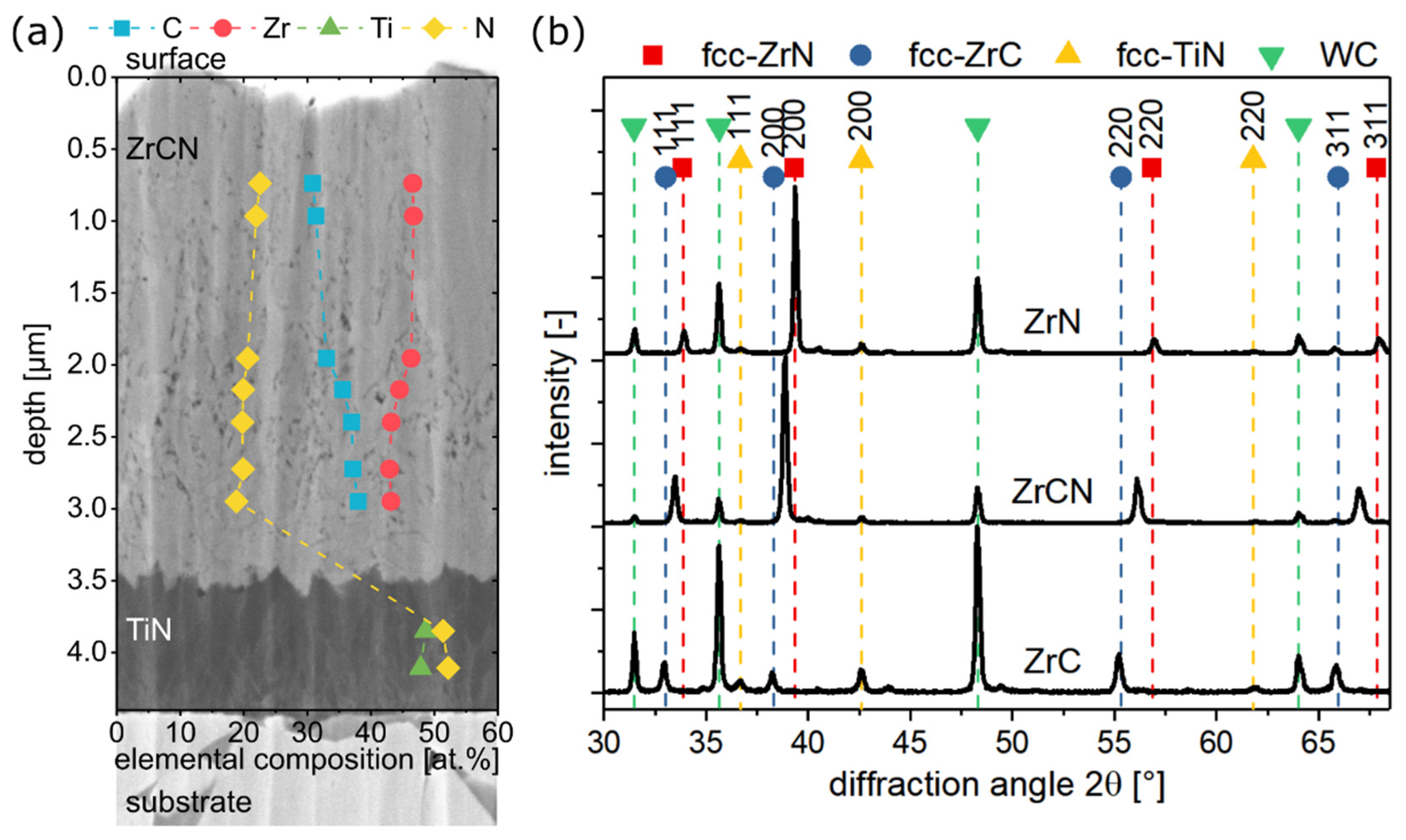
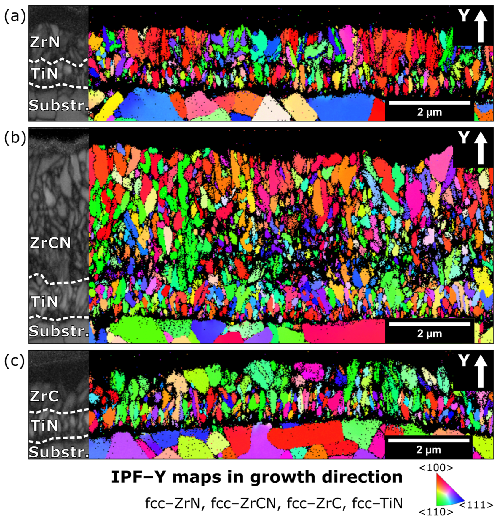
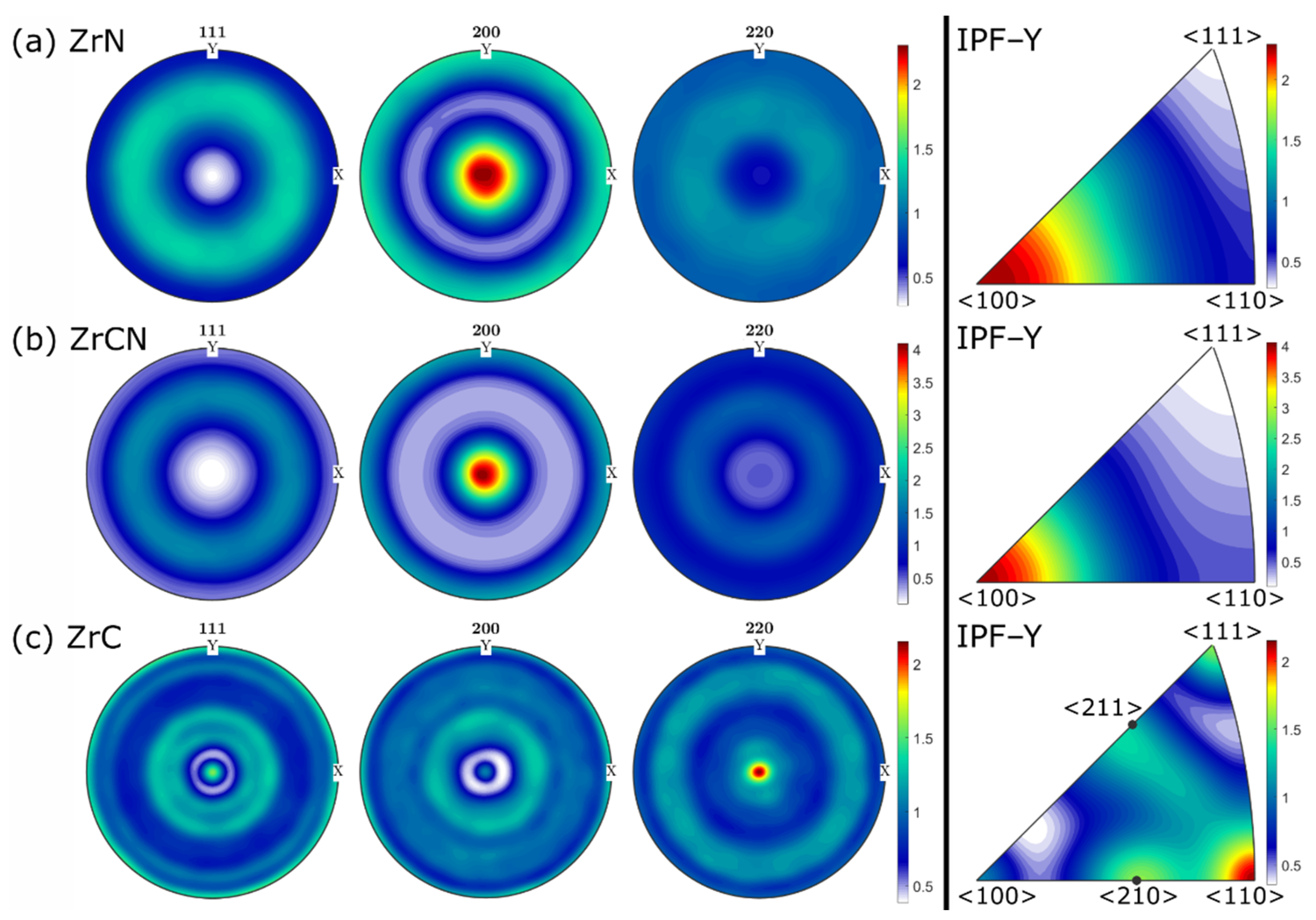
3.1. Chemical Composition and Microstructure

The elemental analysis obtained from EDX showed a mean Zr content of ~50 at.% for the ZrN and slightly lower values of ~45 at.% for the ZrCN and ZrC coatings. Small amounts of C (~7 at.%) were detected in the ZrN coating, which can be related to residual CH3 precursor in the feed gas line. However, due to the limitations of EDX in detecting light elements like C and N, these values have to be treated carefully. A Cl contamination could not be observed in the Zr(C,N) coatings, which can be related to the deposition temperature >900 °C and high H2 carrier gas flow rate [22]. H2 acts as reductant agent for the dissociation of ZrCl4 into ZrCl3, ZrCl2 and ZrCl subchlorides and its presence is necessary to reduce Cl contamination. The ZrCN coating contained ~21 at.% N and ~34 at.% C, which led to a normalized composition of ZrC0.62N0.38 regarding the C/(C + N) ratio. This C/(C + N) ratio is in good agreement with ratios obtained for CVD TiCN coatings deposited from the TiCl4-CH3CN-H2 system at temperatures >850 °C [38,39,40]. In addition to the mean coating composition, also compositional depth profiling recorded by EDX was conducted for the ZrCN coating. The results are shown in Figure 1a. The analysis revealed an increase in C content of ~7 at.% towards the TiN base layer. The origin of this C increase is not completely clear. Even though the TiN base layer acts as diffusion barrier, the diffusion of small amounts of C from the cemented carbide substrate through this layer cannot be excluded [41]. The C increase may also arise from the precursor gas due to not optimized process parameters.
X-ray diffractograms of all three coating systems are displayed in Figure 1b. The standard peak positions of face-centered cubic (fcc)–ZrN (PDF 00-035-0753 [42]), fcc–ZrC (PDF 00-035-0784 [42]), fcc–TiN (PDF 00-038-1420 [42]) and WC (PDF 00-051-0939 [42]) arising from the cemented carbide substrate, are plotted as dashed lines. All Zr(C,N) layers, as well as the TiN base layer, exhibited a fcc structure. The peaks of the ZrN and ZrC coatings were in good agreement with the standard peak positions, while the ZrCN peak lay between the ZrN and ZrC peaks, due to the formation of a solid solution. A detailed Rietveld refinement of the XRD patterns of the powdered coatings revealed a lattice parameter of 0.458 ± 0.001 nm and 0.470 ± 0.001 nm for ZrN and ZrC, respectively, which is in excellent agreement with the lattice parameters given in the respective ICDD cards (0.458 nm for ZrN and 0.469 nm for ZrC). Considering the formation of a solid solution and a Vegard-like behavior, the determined lattice parameter for ZrCN of 0.463 ± 0.001 nm led to a normalized composition of ZrC0.39N0.61, which was in contrast to the EDX measurement yielding ZrC0.62N0.38. This deviation can most probably be attributed to excess C in the coating, which was not incorporated in the ZrCN lattice and consequently did not affect the lattice parameter.
In Figure 2a, SEM micrographs of the surfaces of the ZrN, ZrCN and ZrC coatings are shown. The ZrN coating exhibited a needle-like (lenticular) surface morphology, which was also reported by Russel et al. for CVD ZrN coatings, deposited at temperatures below 1050 °C [14]. The surface of the ZrCN coating showed a rugged and apparently porous structure. Kudapa et al. observed a needle-like surface morphology for CVD ZrCN coatings, deposited at moderate temperatures [18]. Similar to the ZrN coating, the surface morphology of the ZrC coating was also needle-like. However, while the lengths of the needles were comparable (~1 µm), the aspect ratio was smaller for the ZrC coating compared to the ZrN coating. SEM micrographs of the FIB-prepared cross-sections of all three coatings are depicted in Figure 2b. The TiN base layer and the respective ZrN, ZrCN and ZrC layer can be clearly distinguished. A difference in coating thickness between the three samples is clearly visible. While the ZrN and ZrC layers showed a comparable thickness of 0.99 ± 0.09 µm and 0.87 ± 0.06 µm, respectively, the ZrCN layer exhibited a thickness of 3.53 ± 0.13 µm. Since the deposition time and the temperature were constant for all three coatings, the different feed gas composition is assumed to be mainly responsible for the variations in the coating thickness and consequently the deposition rate. In addition to the different reactivity of the three precursors CH3CN, CH4 and N2, also the H2 carrier gas flow rate can influence the coating thickness [22]. The deposition rate was the highest for the ZrCN coating with 0.81 ± 0.01 µm/h, while the rates for the ZrN and ZrC coatings were 0.23 ± 0.01 µm/h and 0.20 ± 0.01 µm/h, respectively. These results indicate a high yield from the CH3CN precursor, used for the deposition of ZrCN, and significantly lower yields for the deposition with N2 and CH4 for ZrN and ZrC, respectively, at identical deposition temperatures of 1000 °C. This can be attributed to the lower energy needed for the dissociation of the organic CH3CH precursor than for N2 and CH4 [39,40,43]. Competitive growth was observed for the TiN base layer of all coatings. The smaller grains at the interface were followed by columnar grains, which extended through the base layer. Within the ZrN and ZrC layers’ columnar grains, extension through the whole layer was observed. In the ZrCN FIB cross-section, columnar grains were visible as well, but they did not extend through the whole layer. The grain growth was repeatedly interrupted, especially at the beginning of the layer. Furthermore, the mean grain length in growth direction increased in size with increasing coating thickness, which is typical for the competitive growth mechanism [44,45]. The porous structure of the ZrCN coating, supposed from the surface micrograph, is also evident in the FIB cross-section. The pores might be related to the excess C, which was not incorporated in the ZrCN lattice, as shown by EDX and XRD analysis (Figure 1). It appears that the number of pores increased towards the TiN interface, which was in good agreement with the accompanied increase in C content (Figure 1a). Both the surfaces and the FIB cross-sections of all coatings were inspected by SEM on a bigger scale (115 × 115 µm2 surface and 11 × 11 µm2 cross-section, images not shown) and no cracks were found.
To gain further insight into the microstructure of the coatings, detailed EBSD investigations, shown in Figure 3, were conducted. On the far left side, the respective band contrast images, corresponding to the inverse pole maps in growth direction (IPF–Y maps) on the right side, are shown. The orientation of the grains is color coded. The color code valid for the coating is given at the bottom right of Figure 3. This color code is not valid for the substrate, which was not in the focus of this work. The competitive growth in the TiN layer already seen in the SEM micrographs of the FIB cross-sections in Figure 2b was also visible in the EBSD images for all coatings. In the ZrN layer (Figure 3a), mainly columnar grains were present, which extended through the whole layer. The ZrCN layer (Figure 3b) exhibited a heterogeneous distribution of columnar grains and small globular grains at the TiN/ZrCN interface. As already mentioned above, the columnar grains, as well as the globular grains, increased in size with the layer thickness. Similar to the ZrN coating, the ZrC coating (Figure 3c) exhibited columnar grains, which extended over the whole thickness of the ZrC layer, however, compared to the ZrN layer also some rounder grains with lower aspect ratio were observed. The broader appearance of the grains was in good agreement with the surface micrograph (Figure 2a), where also broader needles were observed for the ZrC compared to the ZrN coating. The grain orientation in growth direction seemed random for all three coatings and considering only the EBSD images, no clear statement can be made regarding a preferred orientation of the coatings. Due to the small cross-sections in relation to the grain sizes, a statistical evaluation of the grain orientation distribution was not considered.
Therefore, to gain further insight into the texture of the coatings, XRD PFs were recorded. The recalculated PFs of the 111, 200 and 220 reflexes, as well as the calculated IPFs in growth direction, are shown in Figure 4a–c for the ZrN, ZrCN and ZrC coatings, respectively. The intensities of the PFs were normalized within each coating system. All PFs exhibited rotational symmetric intensity distributions, indicating a fiber texture for all coating systems. The IPFs for the ZrN (Figure 4a) and ZrCN (Figure 4b) coatings revealed a distinct <100> preferred orientation. These results were in good agreement with the XRD patterns (Figure 1b), where 200 was identified as the strongest peak for ZrN and ZrCN. Russel found a <100> preferred orientation for ZrN coatings deposited at 1050 °C and a <111> or <110> preferred orientation for coatings deposited at lower temperatures of ~900 to 975 °C, indicating a pronounced texture dependency on the deposition temperature [14]. As opposed to the ZrN and ZrCN coatings, the IPF of the ZrC (Figure 4c) coating exposed a <110> preferred orientation in growth direction. However, the texture was not that pronounced and some grains were oriented in <111>, <210> and <211> directions. Although the layer thickness might influence the texture of the coatings [39], a change in texture could also be related to the different precursor compositions, as the ZrN and ZrC coatings exhibited a similar thickness but different texture. Park et al. investigated the influence of the H2 concentration on the microstructure of ZrC coatings, using a ZrCl4-CH4-H2-Ar precursor system at temperatures of 1350 °C. They varied the H2 to Ar gas ratio and found that a high H2 concentration was accompanied by a 220 preferred orientation, in contrast to low H2 concentrations that led to 111 and 200 orientations [46]. The same effect of the H2 concentration on the texture in CVD ZrC coatings, deposited from different precursor systems with temperatures >1000 °C, has been observed by several researchers [19,47,48]. One possible explanation for this change in texture was given by Imai et al. and can be related to a varying critical size for nucleus growth in different crystallographic orientations with changing supersaturation of the precursor gases. Hereby, the preferred orientation changed from 111 to 001 and 110 with increasing H2 partial pressure [49]. Since the H2 concentration was high for the deposition of the ZrC coating, the results of the texture analysis are in accordance with these reports.

3.2. Residual Stress and Mechanical Properties

The determined residual stresses are displayed in Figure 5a. All coatings showed tensile stresses that arose due to the mismatch in the CTE between the substrate and the coating material (ΔCTE) [50]. According to literature, the CTEs for ZrN and ZrC are 7.2 × 10⁻⁶ K−1 and 6.7 × 10⁻⁶ K−1, respectively [51]. Considering the determined composition for the ZrCN coating, a linear interpolation of these two values yielded a CTE of 6.95 × 10⁻⁶ K−1. Consequently, the CTE of all coatings were higher compared to the one of the cemented carbide substrate (5.7 × 10⁻⁶ K−1 [50]), resulting in a more pronounced contraction of the coating than the substrate material during the cooling process after deposition [13]. The observed decrease of the tensile stresses from ZrN over ZrCN to ZrC coatings was in agreement with the CTEs of the individual coating systems. Since the main contribution to the stress state in CVD coatings is thermal stress (σthermal), the calculated values for these stresses are shown as a comparison to the measured residual stresses. σthermal was calculated according to Gao et al. [52] using
σ thermal = E c 1 ν c   ( α c α s ) Δ T ,
where E is the Young’s modulus, ν the Poisson’s ratio, αc,s the CTE, ΔT is the difference between the deposition and the room temperatures and the subscripts c and s denote the coating or the substrate, respectively. The corresponding values for E were experimentally determined by nanoindentation within this work (Figure 5b), while the values for ν were obtained from literature and were 0.25, 0.21 and 0.20 for ZrN, ZrCN and ZrC, respectively [33]. Although the theoretical thermal stresses followed the trend of the measured residual stresses, deviations of ~410 GPa and ~330 GPa could be observed for the ZrCN and ZrC coatings, respectively. The source of these deviations is not clear; however, it can be speculated that some form of stress relaxation mechanism, either during coating growth or the cooling process, might take place. Since no stress relaxation through crack formation was observed, either plastic deformation of the cemented carbide substrate upon cooling might take place [27], or, as El Azhari et al. suggested, compressive intrinsic stresses, like defect incorporation, formation of nonequilibrium structures or grain boundary relaxation, could develop during the deposition process [13]. Due to the mainly thermal dominated stresses in CVD coatings, the differences in the coating thickness are expected to play a minor role for the residual stresses. By employing the classical laminate theory, residual stresses of the substrate-coating system can be calculated and the influence of the layer thickness on the stress state in the individual layers can be estimated [53,54,55]. Since the thickness of the substrate was ~4.5 mm, variations in the comparably thin Zr(C,N) layer thickness from 1 µm to 5 µm led to no significant influence on the residual stress state in the Zr(C,N) layer. Thus it was assumed that the residual stress measurements were comparable between the three coatings, although the layer thickness varied between ~1 µm (ZrN, ZrC) and ~3.5 µm (ZrCN).
Hardness and Young’s modulus of the ZrN, ZrCN and ZrC coatings are shown in Figure 5b. With the addition of C to ZrN, a hardness increase from 22.1 ± 0.9 GPa for the ZrN coating to 26.1 ± 1.6 GPa for the ZrCN coating was observed. This enhancement can be attributed to solid solution strengthening, as well as an increase of the covalent contribution to the bond strength between the p-states originating from C and the d-states from Zr [16]. The ZrC coating exhibited an even higher hardness of 28.1 ± 1.0 GPa, which complied with the stronger covalent bonding characteristics. This trend of increasing hardness with increasing C/(C + N) ratio was also observed by Yang et al. in Zr(C,N) bulk materials [56]. Furthermore, the Young’s modulus was also affected by the C and N content and showed a maximum for the ZrCN coating (514 ± 19 GPa), followed by a slightly lower value for the ZrC coating (472 ± 22 GPa), while the ZrN coating exhibited the lowest value of 428 ± 10 GPa. This trend was expected and confirmed by first-principles density functional theory calculations by Ivashchenko et al., as well as by experimental findings for Zr(C,N) and Ti(C,N), and can be related to the electronic band structure of the coatings [33,56,57,58]. The influence of the observed pores in the ZrCN coating on the Young’s modulus was expected to be minor, since the porosity was low and the pores were mainly located close to the interface to the TiN base layer [59]. Hardness and Young’s modulus are not only determined by the electronic band structure, but also by the microstructure and the coating thickness. As the grain size tends to increase with increasing coating thickness as a result of competitive growth, a dependency of the hardness and the Young’s modulus on the coating thickness cannot be excluded [44,45,60].

4. Conclusions

Within this study, ZrN, ZrCN and ZrC coatings were successfully deposited by chemical vapor deposition on an industrial scale at 1000 °C, using the precursors ZrCl4-N2-H2, ZrCl4-CH3CN-H2 and ZrCl4-CH4-H2, respectively. The microstructure and mechanical properties of the coatings were investigated. The considerably higher deposition rate for the ZrCN coating with 0.81 ± 0.01 µm/h compared to 0.23 ± 0.01 µm/h and 0.20 ± 0.01 µm/h for the ZrN and ZrC coatings, respectively, can be related to the higher reactivity of the organic CH3CN precursor compared to the less reactive N2 and CH4. The ZrN and ZrC coatings showed a needle-like surface morphology, whereas the ZrCN coating exhibited a rugged and porous structure. Columnar grain growth and fiber texture were observed in all three coatings. While the ZrN and ZrCN coatings exhibited a preferred <100> orientation in growth direction, the ZrC coating showed a <110> texture with few grains oriented in <111>, <210> and <211> directions. These differences in texture were associated with the high H2 precursor concentration in the ZrC coating. The tensile residual stresses decreased from ZrN over ZrCN to ZrC coatings, which can be attributed to the decreasing mismatch in the coefficient of thermal expansion between the cemented carbide substrate and coating material. Upon C addition, the hardness measurements of the coatings increased as a result of solid solution strengthening, as well as the more pronounced covalent bonding character, leading to the lowest values of 22.1 ± 0.9 GPa for the ZrN coating, followed by 26.1 ± 1.6 GPa for the ZrCN and 28.1 ± 1.0 GPa for the ZrC coatings, respectively. Young’s modulus showed a maximum for the ZrCN coating of 514 ± 19 GPa, followed by the ZrC coating with 472 ± 22 GPa and the ZrN coating with 428 ± 10 GPa. In conclusion, the present work provides a fundamental understanding of the microstructure and mechanical properties of CVD Zr(C,N) coatings and is a first step towards the future optimization of this coating system on an industrial scale.

Author Contributions

Conceptualization, F.F.; methodology, F.F. and M.T.; validation, F.F. and M.T.; formal analysis, F.F.; investigation, F.F. and M.T.; resources, C.C.; writing—original draft preparation, F.F.; writing—review and editing, M.T., C.C., and N.S.; visualization, F.F.; supervision, M.T. and N.S.; project administration, N.S.; funding acquisition, C.C. and N.S. All authors have read and agreed to the published version of the manuscript.

Funding

The financial support by the Austrian Federal Ministry for Digital and Economic Affairs and the National Foundation for Research, Technology and Development is gratefully acknowledged. The authors gratefully acknowledge the financial support under the scope of the COMET program within the K2 Center “Integrated Computational Material, Process and Product Engineering (IC–MPPE)” (Project No. 859480). This program is supported by the Austrian Federal Ministries for Transport, Innovation and Technology (BMVIT) and for Digital and Economic Affairs (BMDW), represented by the Austrian research funding association (FFG), and the federal states of Styria, Upper Austria and Tyrol.

Institutional Review Board Statement

Not applicable.

Informed Consent Statement

Not applicable.

Data Availability Statement

Data are contained within the article. Raw data are available on request.

Acknowledgments

The authors want to thank Bernhard Sartory (Materials Center Leoben) for the SEM and EBSD investigations.

Conflicts of Interest

The authors declare no conflict of interest.

References

  1. Mitterer, C. PVD and CVD Hard Coatings. In Comprehensive Hard Materials; Sarin, V.K., Ed.; Elsevier Ltd.: Amsterdam, The Netherlands, 2014; Volume 2, pp. 449–467. ISBN 9780080965284. [Google Scholar]
  2. Kainz, C.; Schalk, N.; Tkadletz, M.; Mitterer, C.; Czettl, C. Microstructure and mechanical properties of CVD TiN/TiBN multilayer coatings. Surf. Coat. Technol. 2019, 370, 311–319. [Google Scholar] [CrossRef]
  3. Schintlmeister, W.; Wallgram, W.; Kanz, J.; Gigl, K. Cutting tool materials coated by chemical vapour deposition. Wear 1984, 100, 153–169. [Google Scholar] [CrossRef]
  4. Kainz, C.; Schalk, N.; Tkadletz, M.; Mitterer, C.; Czettl, C. The effect of B and C addition on microstructure and mechanical properties of TiN hard coatings grown by chemical vapor deposition. Thin Solid Film. 2019, 688, 137283. [Google Scholar] [CrossRef]
  5. Wagner, J.; Mitterer, C.; Penoy, M.; Michotte, C.; Wallgram, W.; Kathrein, M. The effect of deposition temperature on microstructure and properties of thermal CVD TiN coatings. Int. J. Refract. Met. Hard Mater. 2008, 26, 120–126. [Google Scholar] [CrossRef]
  6. Rie, K.-T.; Wöhle, J. Plasma-CVD of TiCN and ZrCN films on light metals. Surf. Coat. Technol. 1999, 112, 226–229. [Google Scholar] [CrossRef]
  7. Rie, K.-T.; Gebauer, A.; Wöhle, J. Plasma assisted CVD for low temperature coatings to improve the wear and corrosion resistance. Surf. Coat. Technol. 1996, 86-87, 498–506. [Google Scholar] [CrossRef]
  8. Haubner, R.; Rauchenwald, E.; Lessiak, M.; Pitonak, R.; Weissenbacher, R. Novel High-Performance CVD Coatings for Machining Applications. Powder Met. Prog. 2018, 18, 128–138. [Google Scholar] [CrossRef] [Green Version]
  9. Huang, J.-H.; Kuo, K.-L.; Yu, G.-P. Oxidation behavior and corrosion resistance of vacuum annealed ZrN-coated stainless steel. Surf. Coat. Technol. 2019, 358, 308–319. [Google Scholar] [CrossRef]
  10. Garcia, J.; Moreno, M.F.; Östby, J.; Persson, J.; Pinto, H.C. Design of coated cemented carbides with improved comb crack resistance. In Proceedings of the 19th Plansee Semin, Reutte, Austria, 29 May–2 June 2017. [Google Scholar]
  11. Ul-Hamid, A. Microstructure, properties and applications of Zr-carbide, Zr-nitride and Zr-carbonitride coatings: A review. Mater. Adv. 2020, 1, 1012–1037. [Google Scholar] [CrossRef]
  12. El Azhari, I.; Garcia, J.; Zamanzade, M.; Soldera, F.; Pauly, C.; Llanes, L.; Mücklich, F. Investigations on micro-mechanical properties of polycrystalline Ti(C,N) and Zr(C,N) coatings. Acta Mater. 2018, 149, 364–376. [Google Scholar] [CrossRef] [Green Version]
  13. El Azhari, I.; García, J.; Soldera, F.; Suarez, S.; Jiménez-Piqué, E.; Mücklich, F.; Llanes, L. Contact damage investigation of CVD carbonitride hard coatings deposited on cemented carbides. Int. J. Refract. Met. Hard Mater. 2020, 86, 105050. [Google Scholar] [CrossRef]
  14. Russell, W.C. Experimental Design Approach to Development of a CVD ZrN Coating. Le J. Phys. Colloq. IV 1995, 5, C5–C127. [Google Scholar] [CrossRef]
  15. Long, Y.; Javed, A.; Chen, J.; Chen, Z.-K.; Xiong, X. Phase composition, microstructure and mechanical properties of ZrC coatings produced by chemical vapor deposition. Ceram. Int. 2014, 40, 707–713. [Google Scholar] [CrossRef]
  16. Sundgren, J.-E.; Hentzell, H.G. A review of the present state of art in hard coatings grown from the vapor phase. J. Vac. Sci. Technol. A Vac. Surf. Film. 1986, 4, 2259–2279. [Google Scholar] [CrossRef]
  17. El Azhari, I.; Barrirero, J.; García, J.; Soldera, F.; Llanes, L.; Mücklich, F. Atom Probe Tomography investigations on grain boundary segregation in polycrystalline Ti(C,N) and Zr(C,N) CVD coatings. Scr. Mater. 2019, 162, 335–340. [Google Scholar] [CrossRef] [Green Version]
  18. Kudapa, S.; Narasimhan, K.; Boppana, P.; Russell, W.C. Characterization and properties of MTCVD TiCN and MTCVD ZrCN coatings. Surf. Coat. Technol. 1999, 120-121, 259–264. [Google Scholar] [CrossRef]
  19. Liu, Q.; Zhang, L.; Cheng, L.; Wang, Y. Morphologies and growth mechanisms of zirconium carbide films by chemical vapor deposition. J. Coat. Technol. Res. 2008, 6, 269–273. [Google Scholar] [CrossRef]
  20. Wang, Y.; Liu, Q.; Liu, J.; Zhang, L.; Cheng, L. Deposition Mechanism for Chemical Vapor Deposition of Zirconium Carbide Coatings. J. Am. Ceram. Soc. 2008, 91, 1249–1252. [Google Scholar] [CrossRef]
  21. Zhu, Y.; Cheng, L.; Ma, B.; Gao, S.; Feng, W.; Liu, Y.; Zhang, L. Calculation and synthesis of ZrC by CVD from ZrCl4–C3H6–H2–Ar system with high H2 percentage. Appl. Surf. Sci. 2015, 332, 591–598. [Google Scholar] [CrossRef]
  22. Rauchenwald, E.; Lessiak, M.; Weissenbacher, R.; Haubner, R. Chemical vapor deposition of ZrN using in situ produced ZrCl4 as a precursor. Ceram. Int. 2019, 45, 9410–9414. [Google Scholar] [CrossRef]
  23. Kim, K.H.; Lee, S.H. Comparative studies of TiN and Ti1−xAlxN by plasma-assisted chemical vapor deposition using a TiCl4/AlCl3/N2/H2/Ar gas mixture. Thin Solid Film. 1996, 283, 165–170. [Google Scholar] [CrossRef]
  24. Kawata, K.; Sugimura, H.; Takai, O. Effects of chlorine on tribological properties of TiN films prepared by pulsed d.c. plasma-enhanced chemical vapor deposition. Thin Solid Film. 2002, 407, 38–44. [Google Scholar] [CrossRef]
  25. Rie, K.-T.; Gebauer, A.; Woehle, J. Investigation of PA-CVD of TiN: Relations between process parameters, spectroscopic measurements and layer properties. Surf. Coat. Technol. 1993, 60, 385–388. [Google Scholar] [CrossRef]
  26. Anderbouhr, S.; Ghetta, V.; Blanquet, E.; Chabrol, C.; Schuster, F.; Bernard, C.; Madar, R. LPCVD and PACVD (Ti,Al)N films: Morphology and mechanical properties. Surf. Coat. Technol. 1999, 115, 103–110. [Google Scholar] [CrossRef]
  27. Stylianou, R.; Velic, D.; Daves, W.; Ecker, W.; Stark, A.; Schell, N.; Tkadletz, M.; Schalk, N.; Czettl, C.; Mitterer, C. Stress relaxation through thermal crack formation in CVD TiCN coatings grown on WC-Co with different Co contents. Int. J. Refract. Met. Hard Mater. 2020, 86, 105102. [Google Scholar] [CrossRef]
  28. Gassner, M.; Schalk, N.; Tkadletz, M.; Czettl, C.; Mitterer, C. Thermal crack network on CVD TiCN/α-Al2O3 coated cemented carbide cutting tools. Int. J. Refract. Met. Hard Mater. 2019, 81, 1–6. [Google Scholar] [CrossRef]
  29. ISO 1832:2017(en); Indexable Inserts for Cutting Tools—Designation; International Organization for Standardization: Geneva, Switzerland, 2017.
  30. Bachmann, F.; Hielscher, R.; Schaeben, H. Texture Analysis with MTEX—Free and Open Source Software Toolbox. Solid State Phenom. 2010, 160, 63–68. [Google Scholar] [CrossRef] [Green Version]
  31. Abadias, G.; Chason, E.; Keckes, J.; Sebastiani, M.; Thompson, G.B.; Barthel, E.; Doll, G.L.; Murray, C.E.; Stoessel, C.H.; Martinu, L. Review Article: Stress in thin films and coatings: Current status, challenges, and prospects. J. Vac. Sci. Technol. A Vac. Surf. Film. 2018, 36, 020801. [Google Scholar] [CrossRef] [Green Version]
  32. Hill, R. The Elastic Behaviour of a Crystalline Aggregate. Proc. Phys. Soc. Sect. A 1952, 65, 349–354. [Google Scholar] [CrossRef]
  33. Ivashchenko, V.I.; Turchi, P.E.A.; Shevchenko, V.I. First-principles study of elastic and stability properties of ZrC–ZrN and ZrC–TiC alloys. J. Phys. Condens. Matter 2009, 21, 395503. [Google Scholar] [CrossRef]
  34. Krasnenko, V.; Brik, M.G. First-principles calculations of the structural, elastic and electronic properties of MNxC1−x (M = Ti, Zr, Hf; 0 ≤ x ≤ 1) carbonitrides at ambient and elevated hydrostatic pressure. Solid State Sci. 2014, 28, 1–8. [Google Scholar] [CrossRef] [Green Version]
  35. Wu, Z.; Chen, X.-J.; Struzhkin, V.V.; Cohen, R.E. Trends in elasticity and electronic structure of transition-metal nitrides and carbides from first principles. Phys. Rev. B 2005, 71, 214103. [Google Scholar] [CrossRef] [Green Version]
  36. Chen, X.-J.; Struzhkin, V.V.; Wu, Z.; Somayazulu, M.; Qian, J.; Kung, S.; Christensen, A.N.; Zhao, Y.; Cohen, R.E.; Mao, H.-K.; et al. Hard superconducting nitrides. Proc. Natl. Acad. Sci. USA 2005, 102, 3198–3201. [Google Scholar] [CrossRef] [PubMed] [Green Version]
  37. Oliver, W.C.; Pharr, G.M. An improved technique for determining hardness and elastic modulus using load and displacement sensing indentation experiments. J. Mater. Res. 1992, 7, 1564–1583. [Google Scholar] [CrossRef]
  38. Czettl, C.; Mitterer, C.; Muhle, U.; Rafaja, D.; Puchner, S.; Hutter, H.; Penoy, M.; Michotte, C.; Kathrein, M. CO addition in low-pressure chemical vapour deposition of medium-temperature TiCxN1-x based hard coatings. Surf. Coat. Technol. 2011, 206, 1691–1697. [Google Scholar] [CrossRef]
  39. Larsson, A.; Ruppi, S. Microstructure and properties of Ti(C,N) coatings produced by moderate temperature chemical vapour deposition. Thin Solid Film. 2002, 402, 203–210. [Google Scholar] [CrossRef]
  40. Bonetti, R.S.; Wiprächtiger, H.; Mohn, E. CVD of titanium carbonitride at moderate temperature: Properties and applications. Met. Powder Rep. 1990, 45, 837–840. [Google Scholar] [CrossRef]
  41. Sabitzer, C.; Steinkellner, C.; Koller, C.M.; Polcik, P.; Rachbauer, R.; Mayrhofer, P.H. Diffusion behavior of C, Cr, and Fe in arc evaporated TiN- and CrN-based coatings and their influence on thermal stability and hardness. Surf. Coat. Technol. 2015, 275, 185–192. [Google Scholar] [CrossRef]
  42. Gates-Rector, S.; Blanton, T. The Powder Diffraction File: A quality materials characterization database. Powder Diffr. 2019, 34, 352–360. [Google Scholar] [CrossRef] [Green Version]
  43. Dreiling, I.; Haug, A.; Holzschuh, H.; Chassé, T. Raman spectroscopy as a tool to study cubic Ti–C–N CVD coatings. Surf. Coat. Technol. 2009, 204, 1008–1012. [Google Scholar] [CrossRef]
  44. Pierson, H.O. Handbook of Chemical Vapor Deposition (CVD), 2nd ed.; Noyes Publications: Park Ridge, IL, USA, 1999; ISBN 0815514328. [Google Scholar]
  45. Thompson, C.V. Structure Evolution during Processing of Polycrystalline Films. Annu. Rev. Mater. Sci. 2000, 30, 159–190. [Google Scholar] [CrossRef]
  46. Park, J.H.; Jung, C.H.; Kim, D.J.; Park, J.Y. Effect of H2 dilution gas on the growth of ZrC during low pressure chemical vapor deposition in the ZrCl4–CH4–Ar system. Surf. Coat. Technol. 2008, 203, 87–90. [Google Scholar] [CrossRef]
  47. Sun, W.; Xiong, X.; Huang, B.Y.; Li, G.D.; Zhang, H.B.; Xiao, P.; Chen, Z.K.; Zheng, X.L. Microstructural Control of Zirconium Carbide Coating Prepared by Chemical Vapor Deposition. ECS Trans. 2009, 25, 291–299. [Google Scholar] [CrossRef]
  48. Wang, S.-L.; Li, K.-Z.; Li, H.-J.; Zhang, Y.-L.; Wang, Y.-J. Effects of microstructures on the ablation behaviors of ZrC deposited by CVD. Surf. Coat. Technol. 2014, 240, 450–455. [Google Scholar] [CrossRef]
  49. Imai, Y.; Mukaida, M.; Watanabe, A.; Tsunoda, T. Formation energies of two-dimensional nuclei randomly-generated on (001), (110), and (111) planes of a face-centered-cubic crystal. Thin Solid Film. 1997, 300, 305–313. [Google Scholar] [CrossRef]
  50. Stylianou, R.; Velic, D.; Daves, W.; Ecker, W.; Tkadletz, M.; Schalk, N.; Czettl, C.; Mitterer, C. Thermal crack formation in TiCN/α-Al2O3 bilayer coatings grown by thermal CVD on WC-Co substrates with varied Co content. Surf. Coat. Technol. 2020, 392, 125687. [Google Scholar] [CrossRef]
  51. Pierson, H.O. Handbook of Refractory Carbides and Nitrides: Properties, Characteristics, Processing and Applications, 1st ed.; Noyes Publications: New York, NY, USA, 1996; ISBN 9780815513926. [Google Scholar]
  52. Gao, C.; Zhao, Z.; Li, X. Modeling of thermal stresses in elastic multilayer coating systems. J. Appl. Phys. 2015, 117, 055305. [Google Scholar] [CrossRef]
  53. Pister, K.S. Flexural Vibration of Thin Laminated Plates. J. Acoust. Soc. Am. 1959, 31, 233–234. [Google Scholar] [CrossRef]
  54. Reissner, E.; Stavsky, Y. Bending and Stretching of Certain Types of Heterogeneous Aeolotropic Elastic Plates. J. Appl. Mech. 1961, 28, 402–408. [Google Scholar] [CrossRef]
  55. Chair of Strucural and Functional Ceramics, Classical Laminate Theory (CLT). Available online: https://www.isfk.at/de/1428/ (accessed on 2 November 2020).
  56. Yang, Q.; Lengauer, W.; Koch, T.; Scheerer, M.; Smid, I. Hardness and elastic properties of Ti(CxN1−x), Zr(CxN1−x) and Hf(CxN1−x). J. Alloys Compd. 2000, 309, L5–L9. [Google Scholar] [CrossRef]
  57. Jhi, S.-H.; Ihm, J.; Louie, S.G.; Cohen, M.L. Electronic mechanism of hardness enhancement in transition-metal carbonitrides. Nat. Cell Biol. 1999, 399, 132–134. [Google Scholar] [CrossRef]
  58. Ivashchenko, V.I.; Turchi, P.E.A.; Gonis, A.; Ivashchenko, L.A.; Skrynskii, P.L. Electronic origin of elastic properties of titanium carbonitride alloys. Met. Mater. Trans. A 2006, 37, 3391–3396. [Google Scholar] [CrossRef]
  59. Kováčik, J. Correlation between Young’s modulus and porosity in porous materials. J. Mater. Sci. Lett. 1999, 18, 1007–1010. [Google Scholar] [CrossRef]
  60. Bouzakis, K.-D.; Hadjiyiannis, S.; Skordaris, G.; Mirisidis, I.; Michailidis, N.; Efstathiou, K.; Pavlidou, E.; Erkens, G.; Cremer, R.; Rambadt, S.; et al. The effect of coating thickness, mechanical strength and hardness properties on the milling performance of PVD coated cemented carbides inserts. Surf. Coat. Technol. 2004, 177, 657–664. [Google Scholar] [CrossRef]
Figure 1. (a) Cross-sectional SEM image, superimposed by the elemental composition of the ZrCN coating determined by energy dispersive X-ray spectroscopy (EDX) at different depths in the ZrCN coating and (b) X-ray diffractograms of ZrN, ZrCN and ZrC coatings on cemented carbide substrates with TiN base layers.
Coatings 11 00491 g001
Figure 2. (a) SEM surface images and (b) SEM images of the focused ion beam (FIB) prepared cross-sections of the ZrN, ZrCN and ZrC coatings. Note the different scale bar in the FIB cross-section micrograph of the ZrCN coating.
Coatings 11 00491 g002
Figure 3. Electron backscatter diffraction (EBSD) inverse pole figure (IPF) maps of the FIB-prepared cross-section in growth direction (“IPF–Y maps”) for the (a) ZrN, (b) ZrCN and (c) ZrC coatings. The respective Zr(C,N) and TiN layers are indicated in the EBSD band contrast sections on the left. The IPF–Y color code is given at the bottom right for face-centered cubic (fcc) phases. This color code is not valid for the substrate, which was not in the focus of this work.
Coatings 11 00491 g003
Figure 4. Recalculated X-ray diffraction pole figures for the (a) ZrN, (b) ZrCN and (c) ZrC coatings with their corresponding IPFs in growth direction (“IPF–Y”) on the right side.
Coatings 11 00491 g004
Figure 5. (a) Experimentally determined (σexp) and calculated thermal stresses (σthermal) as well as coefficient of thermal expansion (CTE) mismatch (ΔCTE) between the substrate and the investigated Zr(C,N) coatings. (b) Hardness measurements (H) and Young’s moduli (E) of the Zr(C,N) coatings.
Coatings 11 00491 g005
Table 1. Deposition parameters (time, temperature, total pressure and gas flow rates) for ZrN, ZrCN and ZrC.
SampleTime
[min]
Temperature
[°C]
Pressure
[kPa]
H2 (Balance)
[vol.%]
N2
[vol.%]
CH3
CN[vol.%]
CH4
[vol.%]
ZrN2601000167624--
ZrCN26010001099.9-2.2 × 10⁻⁵-
ZrC26010001694--6
Publisher’s Note: MDPI stays neutral with regard to jurisdictional claims in published maps and institutional affiliations.

