Article

Synthesis of Cubic Aluminum Nitride (AlN) Coatings through Suspension Plasma Spray (SPS) Technology

Department of Chemical & Biotechnological Engineering, Université de Sherbrooke, Sherbrooke, QC J1K 2R1, Canada
*
Author to whom correspondence should be addressed.
Coatings 2021, 11(5), 500; https://doi.org/10.3390/coatings11050500
Submission received: 11 March 2021 / Revised: 13 April 2021 / Accepted: 15 April 2021 / Published: 23 April 2021
(This article belongs to the Special Issue Plasma Sprayed Coatings)

Abstract

:
Thermal spraying of aluminum nitride (AlN) is a challenging issue because it decomposes at a high temperature. In this work, the use of suspension plasma spray (SPS) technology is proposed for the in situ synthesis and deposition of cubic-structured AlN coatings on metallic substrates. The effects of the nitriding agent, the suspension liquid carrier, the substrate materials and the standoff distance during deposition by SPS were investigated. The plasma-synthesized coatings were analyzed by X-ray diffraction (XRD), optical microscopy (OM) and scanning electron microscopy (SEM). The results show higher AlN content in the coatings deposited on a carbon steel substrate (~82%) when compared to titanium substrate (~30%) or molybdenum (~15%). Melamine mixed with pure aluminum powder produced AlN-richer coatings of up to 82% when compared to urea mixed with the Al (~25% AlN). Hexadecane was a relatively better liquid carrier than the oxygen-rich liquid carriers such as ethanol or ethylene glycol. When the materials were exposed to a molten aluminum–magnesium alloy at 850 °C for 2 h, the corrosion resistance of the AlN-coated carbon steel substrate showed improved performance in comparison to the uncoated substrate.

1. Introduction

1.1. Background

Aluminum nitride (AlN) is a promising material that can find diverse applications in the aluminum industry [1], for example, in crucibles for handling corrosive chemicals and reaction vessels [2]. In addition, AlN has become the key component of semiconductor equipment, which is appropriate in piezoelectric and electronic applications [3]. Some of these amazing properties of AlN are summarized in Table 1, as high thermal conductivity [4], low thermal expansion coefficient [5], and a large band gap, which is a major factor that determines a solid’s electrical conductivity [6], and this makes AlN an electrical insulator. Other characteristics include AlN’s chemical and physical stability at fairly high temperature regions, high hardness [7], and high resistance to molten metals, wear and corrosion [5].
AlN exists in several crystal structures with different properties: hexagonal (wurtzite) crystal structure and two types of cubic structures (rock salt and zinc-blende). The cubic AlN is a metastable phase at ambient conditions, which renders its synthesis a difficult process [8]. In comparison to the hexagonal crystal structure, the rock salt cubic AlN by having a higher symmetry in its crystal structure shows greater thermal conductivity (250–600 W·m−1·K−1), electrical resistivity (1016 Ω·cm) and hardness (4079–5098 Hv) [9].

1.2. Synthesis Methods of AlN

Some of the conventional synthesis methods of AlN powder involve the carbothermal reduction–nitridation of alumina [10], direct nitridation of Al powder [11], non-transferred arc plasma method [12], chemical routes [13], microwave-assisted urea route [14], pulsed laser ablation [15] and transferred type arc plasma [16]. Table 2 and Table 3 summarize the different methods of producing AlN coatings and powder, respectively.
Thermal plasma technology is a well-adapted technology for synthesizing crystalline nano materials because of the fast reaction rates achieved due to the high plasma temperatures [5], its flexibility in the choice of various feedstock materials [38], its high conversion rates and energy efficiency [10] and its rapid quenching [39]. Furthermore, plasma spray technology simplifies the inflight reaction of the precursors and the in situ formation of the coatings in a wide range of thickness. Due to the high reaction rate, a dense coating is produced. Among all the thermal spray methods, plasma spraying is extensively used to produce coatings due to its high enthalpy, with the molten or semi molten particles being propelled to adhere and solidify on the substrate [40]. However, sometimes it is not necessary to melt the particles fully, because it is possible for particles in a semi molten state to be deposited as a coating. Moreover, a thermal plasma process can allow for a wide range of coating thicknesses, stretching from nm to mm [41]. In order for the deposited coating to stick to the substrate, the injected particles must melt or be in semi-molten state when they pass through the hot core of the plasma. The high melting point of AlN (2200 °C) as well as its decomposition at high temperatures does not facilitate the deposition of AlN particles injected through the plasma [41].
Besides ammonia [42], nitrogen gas is usually used as a nitriding agent [32], but recently urea [43], and melamine to produce Si-C-N [44], or AlN ceramics [45] have been proposed for nitriding reactions. Melamine (C3H6N6), an organic compound containing about 67 wt% nitrogen is a trimer of cyanamide, with a 1,3,5-triazine skeleton, that releases nitrogen at high temperatures [46], and has been used to produce AlN powder by mechanochemical reaction with Al [47]. Direct injection of nitriding powders such as urea or melamine with Al into plasma, unlike N2 gas, is challenging, particularly when there are different precursor components with various particle sizes and densities [41].
To alleviate the injection problems, suspension liquids have been employed as carrier media of transporting even nano particles into the high temperature zones of plasma, with the added benefits of providing chemical reactions within the suspension liquid. Indeed, powder precursors are dispersed in the liquid media and when injected into plasma, the liquid phase evaporates, while the solid particles melt and vaporize to form clusters. Suspension plasma spray (SPS) was invented to create a homogenous precursor to facilitate direct injection of small particles into plasma by dispersing them in a liquid carrier [48].
In order to produce a durable coating that can withstand thermal shocks, both the coating and the substrate should ideally have linear thermal expansion coefficient that are similar. Substrate materials should have higher melting points and lower thermal expansion coefficients than Al [49]. An interlayer coating can be used to adapt the expansion coefficient difference [50].

1.3. Non-Wetting Properties

In many material processing techniques, for example, in casting processes, molten metals are ordinarily in direct contact with ceramic refractories. Therefore, the properties of the final alloy product are highly affected by the high-temperature properties of the molten metal as well as the interfacial wetting or reaction phenomena. Many factors influence the wettability of the molten alloy–ceramic system such as the alloying elements, defects, impurities and surface roughness of the refractory [51]. Besides the processing parameters, the interaction between the molten metal and the substrate is one of the key factors considered in choosing a suitable material that will be in direct contact with the molten alloys [52]. It has been reported that when a molten metal and a ceramic substrate are in contact, the wetting of the ceramic substrate is usually accompanied by an interfacial reaction between the metal and the ceramic [53]. Hence, a new composition is formed at the interface during the reaction, and this has a strong effect on the magnitude of the interfacial free energy and subsequently alters the contact angle between the molten metal and the ceramic. The contact angle measurement for an Al-ceramic system is not simple for two main reasons: (a) the oxidation of Al where the oxide layer on Al surface modifies the properties and behavior of the alloy, and (b) Al being a highly reactive metal corrodes the ceramic and its wettability changes over time [54].
Ceramics such as AlN are considered as suitable electrolysis cell material because of their non-wettability and non-reactivity towards molten Al or its salts [55]. Some of these ceramics have been synthesized as coatings using solution precursor plasma spray (SPPS) technology, with the authors investigating the effect of different direct current (DC) plasma parameters such as standoff distance, torch power, number of torch-passes, types of solvents and plasma velocity on the superhydrophibicity properties of the final coating [56]. They concluded that a short standoff distance, a high arc current, a low number of torches passes, the addition of ethanol to the solvent and a high plasma velocity result in a dense superhydrophobic coating. In addition, the coated layer demonstrated a hierarchical surface roughness structure.

1.4. Research Objectives

The objective of this study is to produce cubic AlN-rich coatings deposited on various substrates to improve their corrosion resistance when in contact with molten Al-5 wt% Mg. SPS technology has been chosen because it provides flexibility in the selection of precursors and substrates. Moreover, since the injection rate of the precursor has a significant effect on the reaction and formation of the coating, the powder mixture can be suspended in a liquid carrier at various mass concentrations and injected into plasma using a peristaltic pump. The hypothesis being tested involves investigating the effect of synthesis parameters such as precursor composition, suspension liquid, substrate materials and standoff distance. Coatings were characterized by microscopy and X-ray methods. The anti-wetting properties of AlN were ascertained by the sessile drop test and a corrosion test using liquid Al-5 wt% Mg.

2. Materials and Methods

All experiments involving the synthesis of AlN coatings in this study were carried out using a radio frequency (RF) induction suspension plasma spray (SPS) reactor. The SPS system consists of a plasma chamber and atomization probe (of 7–12 µm water droplet size), a plasma torch (supplied by TEKNA Inc., Sherbrooke, QC, Canada) and a plasma power supply (Lepel Co., Edgewood, NY, USA).

2.1. Materials and Reagents

(a)
Substrates: 12.7 mm × 2.0 mm Titanium disks, Ti (McMaster-Carr, Chicago, IL, USA) of composition Ti (88.10–90.92%), Al (5.50–6.75%), C (0.08%), Fe (0.40% Max), V (3.5–4.5%), and 0–0.30% others; Molybdenum disks, Mo (99%, American element, USA); AISI 1144 Carbon steel disks (McMaster-Carr, Chicago, IL, USA) of mainly Fe with inclusions of composition C (0.40–0.48%), Mn (1.35–1.65%), p (0.04% Max) and S (0.24–0.33%).
(b)
Suspension liquid carriers: Hexadecane (99% C16C34, Sigma Aldrich, St. Louis, MO, USA), ethylene glycol (99.8% C2H6O2, Sigma Aldrich, St. Louis, MO, USA), mineral oil (light oil, C16H10N2Na2O7S2, Sigma Aldrich, St. Louis, MO, USA) and anhydrous ethyl alcohol (C2H5OH, commercial alcohol).
(c)
Powders: Pure aluminum metal powder (99.9% Al, Atlantic equipment engineers) with particle size range (1–35 µm), urea grains (CH₄N₂O, Sigma-V1428), Melamine (99% C3N6H6, Alfa Aesar, Fisher Scientific, Tewksbury, MA, USA).

2.2. Preparation of Substrates

In order to increase surface roughness, the substrates were initially sand blasted by alumina particles to improve the coatings’ sticking efficiency to the substrate. However, contamination was a weakness with this approach since the presence of alumina was detected by XRD in the samples. Therefore, SiC paper (180) was used to scratch the substrates in order to obtain the desired surface roughness (~0.5 µm Ra) and this proved to be more effective.

2.3. Suspension Feedstock for SPS Injection

Metal Al powder was mixed with nitriding agents (either melamine or urea powder) and dispersed in different suspension liquid carriers such as ethanol, ethylene glycol, hexadecane or light mineral oil. First, the Al powder was dispersed in the liquid carrier using an ultrasonic bath to break the agglomerated particles for 10 min. Then, the melamine or urea powder was added to the suspension and the mixture stirred for another hour. The suspension feedstock was finally injected into the plasma using an atomization probe.

2.4. Synthesis of Cubic AlN Coatings by SPS

In preparation, the plasma chamber was first evacuated while purging with an inert gas (Argon, Ar), to obtain the pressure set at 16 kPa. Table 4 provides a summary of the plasma conditions employed for the deposition of the AlN coatings. During the injection of the suspension, the sample holder with the substrate was kept at a constant standoff distance in the plasma plume. In order to produce a homogeneous thin film, the coating was deposited in several spray cycles of typically 200 loops where the sample was mounted on a sliding stage that moves back and forth at a speed of 50 mm per second. In addition, since steady spraying can cause the substrates to overheat, therefore, intermittent deposition by loops allows for some cooling. Moreover, the sample holder is water cooled to protect the substrates from melting. One effective way of avoiding agglomeration of un-vaporized Al droplets on the cold substrate is by preheating the surface that supports the coating. Nevertheless, in this work, the deposition commenced without preheating the substrates because AlN formation is an exothermic reaction [17].

2.5. Materials Characterization

The coatings were characterized by various analytical techniques including X-ray diffraction (XRD) for phase and crystal structure analysis. Optical microscopy (OM) and scanning electron microscopy (SEM) coupled with energy dispersive X-ray spectroscopy (EDX) was used for morphological and elemental analysis. Contact angle measurements between the coatings and water by sessile-drop test were used to determine the wettability of the coatings.

2.5.1. X-ray Diffraction (XRD) Analysis

The samples were analyzed according to the method described in an earlier article using a “Philips Panalytical X’pert PRO MPD” X-ray diffractometer (PANalytical, Almelo, The Netherlands) [57]. The diffractometer uses Cu Kα1 radiation with a wavelength, λ = 1.54 Å, in the 2θ-angle range from 20 to 100°, at a scanning speed of 0.04° 2θ-angle per min and a step size of 0.02° and step time, 0.5 s. Data collection and data analysis was performed using factory installed JADE software (version 7.8.4 @2020-04-23 © MDI). The amount of AlN in the coating was determined by Rietveld quantitative analysis (RQA) in the region of 20–60° 2θ-angle. Although there was some degree of amorphicity displayed by the coatings, phase quantification by RQA using Equation (1) was attempted in order to determine the various amounts of each species in the coatings [58].
W ρ = S ρ ( Z M V ) ρ i = 1 n S i ( Z M V ) i
where W ρ = relative weight fraction of phase ρ in a mixture of n phases, S ρ = Rietveld scale factor, Z = number of formula units per cell, M = mass of the formula unit (in atomic mass units) and V = the unit cell volume (in Å3).

2.5.2. Optical Microscopy (OM)

The Keyence VHX-5000 optical microscope (KEYENCE CORPORATION OF AMERICA, Itasca, IL, USA) was used to investigate the surface properties of coatings in relation to their corrosion resistance when in contact with molten the Al-Mg alloy.

2.5.3. Scanning Electron Microscopy (SEM)

Microscopic imaging by SEM coupled with energy dispersive X-ray spectroscopy (EDX) were used to investigate the morphology, structure, particle size and composition of the materials. In this work, SEM imaging and analysis was done on a “Hitachi S-4700” Field-Emission Scanning Electron Microscope (Hitachi High-Technologies Corporation, Tokyo, Japan), equipped with an EDX X-Max Oxford spectrometer (Abingdon, UK) [57].

2.5.4. Surface Roughness Test and the Coating Thickness Measurements

The surface roughness was measured by Mitutoyo Surftest SJ-210- Series 178-Portable surface roughness tester (Mitutoyo Corporation, Kawasaki-shi, Kanagawa, Japan). The measurement range is automatically set with a resolution between 0.0016 and 0.0256 µm. The stylus material is diamond with a tip radius of 2 µm and the force utilized is 0.75 mN. The surface roughness of the substrate was measured before and after the deposition of the coatings. In addition, the coating thickness of samples was measured by Mitutoyo digital thickness gauge equipped with absolute digimatic indicator.

2.6. Materials Testing

(a)
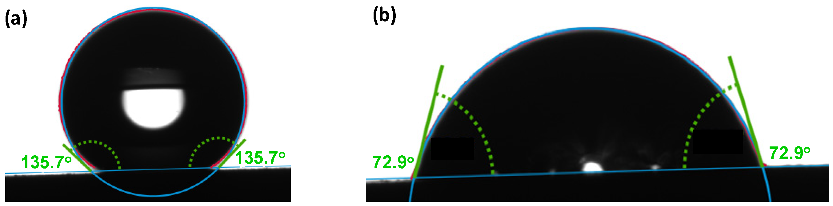
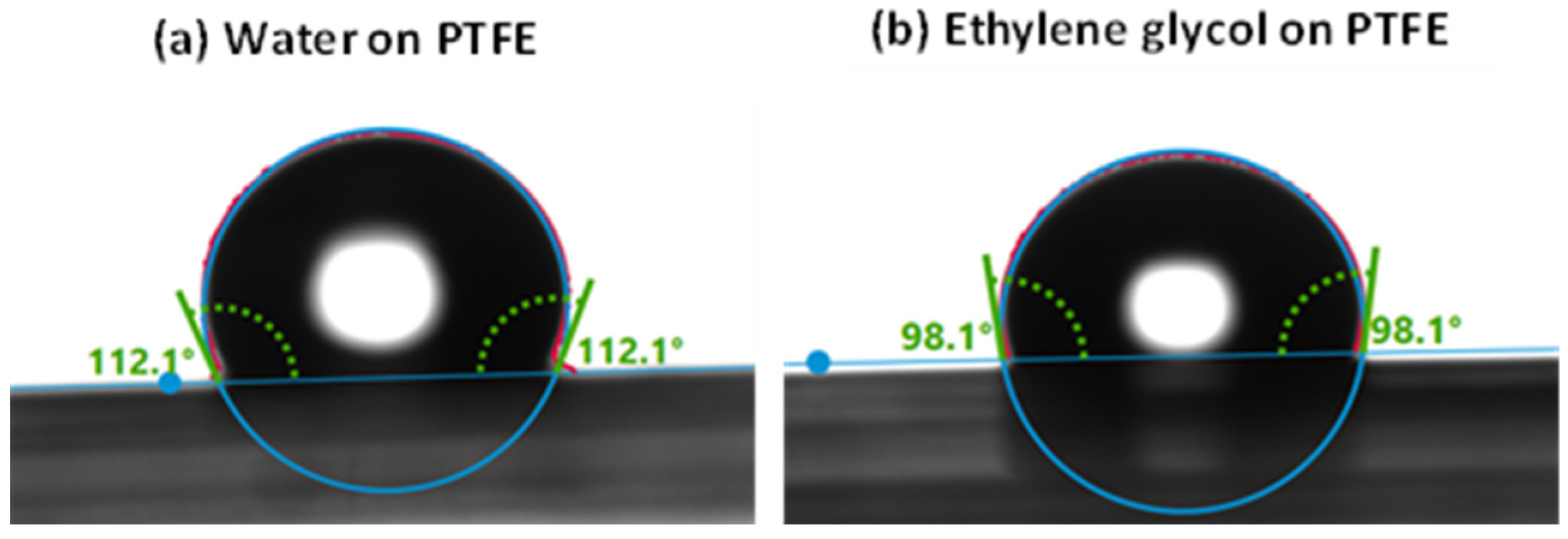
Wetting test: Wettability of the samples was studied using a drop shape analyzer, the Krüss Advance goniometer model DSA25E (KRÜSS, Hamburg, Germany). In order to validate the analysis method, the static contact angle was calibrated at ambient conditions by depositing a droplet of water or ethylene glycol on the surface of Teflon (polytetrafluoroethylene, PTFE). From the manufacturer’s database, the contact angle of water on PTFE is known to be 113.7°, which we validated to be 112.1° as indicated in Figure 1a, while that of ethylene glycol was found to be 98.1° as shown in Figure 1b against 94.9° of the database [59]. A liquid on a solid surface with contact angle below 90° is considered to be a wetting liquid, while a contact angle above 90° indicates non-wetting properties [60]. Superhydrophobic surfaces with the ‘Lotus Effect’ that exhibit an extremely high contact angle with water (>150°) have been broadly investigated and can be considered as a perfect example in anti-corrosion applications [61].
(b)
Corrosion test: The fresh coatings synthesized by SPS technology were tested for corrosion resistance by contacting them directly with a molten Al-alloy containing 5% magnesium (Al-5 wt% Mg) for 2 h at 850 °C. OM was used to observe the surface properties of the coatings to investigate their corrosion resistance when in contact with molten Al-Mg alloy.

3. Results

3.1. FactSage™ Modelling for the In Situ Synthesis of AlN in Plasma

In plasma, at temperatures above 3000 °C, FactSage™ (Montreal, QC, Canada) can predict the composition of materials at thermodynamic equilibrium in vapor phase. At lower temperatures, or when multiphase materials are present, the kinetics of the reactions may be considered, but FactSage™ in our context is used to simulate or predict the outcome of targeted reactions during synthesis and the performance of materials in realistic industrial applications. FactSage™ modelling predicted that using a feedstock of hexadecane, metallic Al and melamine in the presence of plasma gases (including hydrogen and nitrogen), AlN begins to form at temperatures below 2300 °C as portrayed in Figure 2, noting that not all the reactions and species occurring in the simulation results are published on the graph.
Since H2 and N2 gases dissociate to atomic H and N above 5000 °C, the presence of a significant quantity of hydrogen and other gas species in the chamber helps to delay the recombination of nitrogen to N2 at lower temperatures. Gaseous nitrogen is in fact, not a good nitriding agent because when it decomposes to atomic N, it prefers to recombine to N2 instead of reacting with other plasma species. Therefore, NH3 is deemed as a better nitriding agent because once it decomposes at high temperature, it forms N radicals that can react with Al to form AlN. When melamine is injected into the hot core of plasma, it decomposes to nitrogen, hydrogen, ammonia and HCN, besides forming some radicals such as CH˙, NH˙, CN˙, and ions including C2N2+, C3N2+ and C3N3+ that facilitate the reaction with Al to produce AlN.
FactSage™ results in Figure 2 show that at temperatures below 2700 °C, solid carbon starts forming, and at about 700 °C most of the carbon in the chamber is drastically consumed by the formation of CH4. Formation of AlN starts at ~2300 °C through the reaction between Al and HCN. Atomic nitrogen reacts with atomic hydrogen and carbon to form HCN at 4100 °C. As the temperature drops, production of HCN increases to the maximum at 3000 °C. It is confirmed by some authors that the formation of HCN gas plays an important role in producing AlN [62]. It is clear that the role of N2 in the formation of AlN is negligible, but the CN species seems to facilitate the nitridation of Al. Other researchers have demonstrated that at the stoichiometric reactant ratios, the reaction between Al and melamine is mainly governed by the polymerization of melamine and the formation of a carbon nitride (CNx) phase [45].
The presence of oxygen in urea prohibits the nitriding reaction below 1500 °C as predicted from FactSage™ modelling in Figure 3 because it generates alumina (Al2O3). From the quantities produced between the AlN and Al2O3, it is clear that the two products are in direct competition. Therefore, besides using an oxygen-free nitriding agent, the chamber must be evacuated of oxygen to facilitate the reaction between Al and nitrogen. For this reason, suspension liquids with a lot of oxygen such as ethanol and ethylene glycol performed poorly. With urea, the production window of AlN is narrow (1200–2000 °C), while with melamine the AlN’s stability window is wider stretching from 2300 °C to ambient temperature.

3.2. Materials Characterization of AlN Coatings
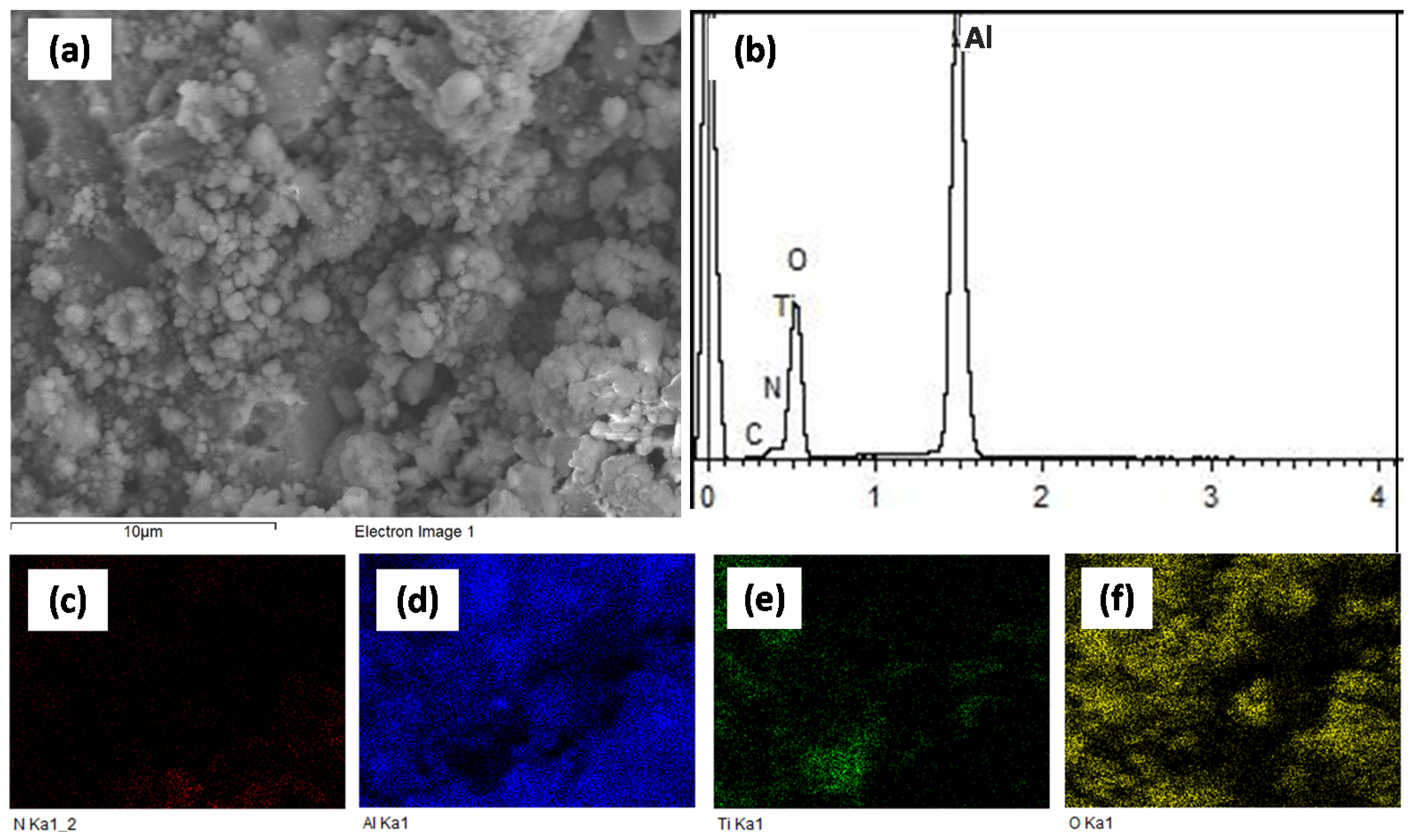
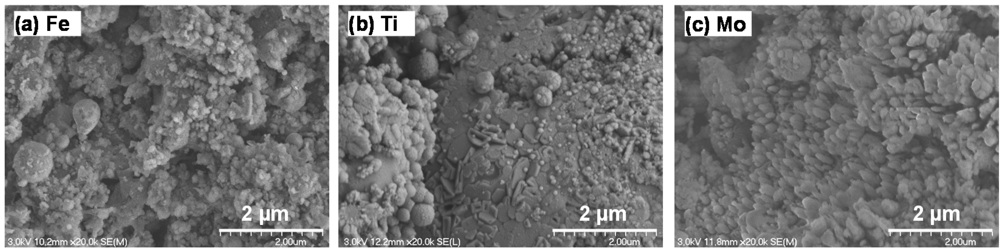
3.2.1. SEM Analysis

The freshly synthesized coatings showed that the splats produced in the plasma were in the mean size range of about 2 µm. A sample secondary electron image (SEI) of AlN coating produced from melamine is presented in Figure 4a,b depicts the mixed color EDX elemental mapping of Al and N, while the individual EDX elemental mappings of Al and N are indicated in Figure 4c,d, respectively. The highly dispersed and concomitant presence of Al and N indicates the success of producing AlN using SPS technology. The EDX spectrum is displayed in Figure 4e. The atomic percentage of each elements calculated by EDX were Al (40%), N (35%) and O (23%) for the coating deposited on carbon steel substrate, and the rest of analysis are summarized in Table 5 for Ti and Mo substrates. Since these values are semi quantitative, they should be used conservatively because of the high surface roughness of the coatings, which normally lowers the signal intensity in some areas under analysis.
Figure 5 provides the surface view of the coating deposited on a carbon steel substrate. The morphology and structure of the coating tend towards agglomerated spherical particles. In addition, Figure 6 displays the cross-sectional view of the same coating showing good bonding between the coating and the substrate. The coating and the bonding remain intact when placed in ultrasonic bath suspended in ethanol for 15 min. Moreover, after exposure to molten Al-Mg alloy, no peeling was observed.

3.2.2. XRD Analysis

Various parameters were used to optimize the production of AlN coating as the target product. Figure 7 shows the XRD patterns of the two major peaks that were used to semi-quantitively determine the amount of the cubic AlN in the coatings, where the main peak at 44.85° 2θ-angle represents the (200) plane, followed by the smaller (111) peak at approximately 38.59° 2θ-angle. A comparatively higher intensity of the (111) peak than the (200) peak implies the presence of metallic Al, while an intense (200) peak accompanied by a smaller (111) peak implies the presence of AlN.
Quantification of the various phases in the AlN coatings by RQA using XRD data is exemplified in Figure 8, which indicates the percentage of the AlN formed in the coatings alongside other by-products. The ICDD cards used to identify the phases include: [00-039-1950] [63] for melamine, [04-010-6160] [64] for Al, [04-007-4280] [65] AlN hexagonal, [04-004-8344] [66] for AlN cubic, [01-088-2331] [67] for Mo, [00-046-1212] [68] for Al2O3, [00-055-0142] for urea, [01-085-4874] [69] for TiAl3, [04-011-9045] for Ti and [04-014-0164] [70] for Fe. This approach was used to analyze all the other samples, where the raw data extracted from the RQA curve fitting are summarized in Table 6.
Further, the quantity of AlN (%) was plotted versus the standoff distance, the substrate materials, the liquid suspension carriers and the nitriding agents as provided in Figure 9. Figure 9a illustrates the impact the substrate materials have on the formation of AlN in the coatings, while Figure 9b shows that comparatively, melamine is a stronger nitridation agent than urea. The presence of oxygen in urea seems to have a negative impact on nitridation reaction because Al has a higher affinity for oxygen than nitrogen. In addition, melamine by having a higher concentration of nitrogen per unit mass than urea increases the chance of the reaction between Al and nitrogen in plasma.
Figure 9c shows the effect of standoff distance on the formation of AlN, with the optimum distance being found to be 8 cm. On one hand, decreasing the standoff distance to 6 cm saw the formation of AlN decrease drastically, because of insufficient residence time for the species to react and produce AlN. On the other hand, increasing the standoff distance to 10 cm equally lowered the production of AlN, although there was enough time for the materials to react. However, by lengthening the residence time, two other negative phenomena emerged: (a) the in situ produced AlN decomposed and could not make it into the coating, and (b) the AlN particles formed and hardened in such a way that they could no longer produce splats onto the substrate. It is necessary that coating materials should be in molten state in order to stick on the substrate. Figure 9d, shows that at standoff distance of 8 cm, using melamine and a carbon steel substrate, the hexadecane liquid carrier produced the highest amount of AlN in the coatings as compared to the other liquid carriers.

4. Discussion

4.1. Effect of Nitriding Agent on AlN Formation

In this study, two nitriding agents were used, namely melamine (C3H6N6) and urea (CH₄N₂O). From the XRD analysis using RQA, it was observed that melamine produced a higher percentage (82%) of AlN in the coatings in comparison to urea (25%). Melamine having more nitrogen in its structure (67% by mass N) than urea (47% by mass N), introduced more nitrogen into the system, thereby increasing the chance of Al reacting with nitrogen. Since the mass transfer in plasma is characterized by the laminar flow, mixing is restricted and any reactant that would increase the chance of reaction is crucial. Figure 10 shows XRD spectra of coatings produced using different nitriding agents. It was observed that in materials where the (200) peak was more intense than the (111) peak, then the material was richer in AlN. However, the presence of metallic Al was characterized by an intense (111) peak accompanied by a smaller (200) peak.
When urea was used as a nitriding agent, there was a dismal conversion of Al to AlN, but melamine produced more AlN under similar plasma conditions. The dominant phase in the AlN was the cubic crystal structure (Fm-3m space group). In effect, urea did not react well with Al, but melamine performed comparatively better. This confirmed what a number of authors have suggested in using melamine as a nitriding agent to generate nano-structured AlN powder [71]. It has been reported that melamine releases NH3 to form a melem (C6N10H6) intermediate at temperatures of about 550 °C, and at higher temperatures to produce chemically reactive hydrogen-, carbon- or nitrogen-containing atomic species such as CN2+ and NCNH+ [72]. CN group is so reactive that it easily produces charged nitriding species in plasma due to the instability of the triple bond between C and N, especially with the presence of the π electron bonds.
Figure 11a shows SEM analysis of the AlN coating produced by urea. Figure 11b is the EDX spectrum of the coating, while Figure 11c–f represents the respective EDX elemental analysis for N, Al, Ti and oxygen. When compared, the coating deposited on Ti substrate using urea, shown in the EDX spectrum of Figure 11b, contained more oxygen and less AlN than the sample derived from melamine, as seen in Figure 4. The atomic percent of elements calculated by EDX were Al (39.9%), N (5.5%), Ti (5.8%) and O (51.4%).

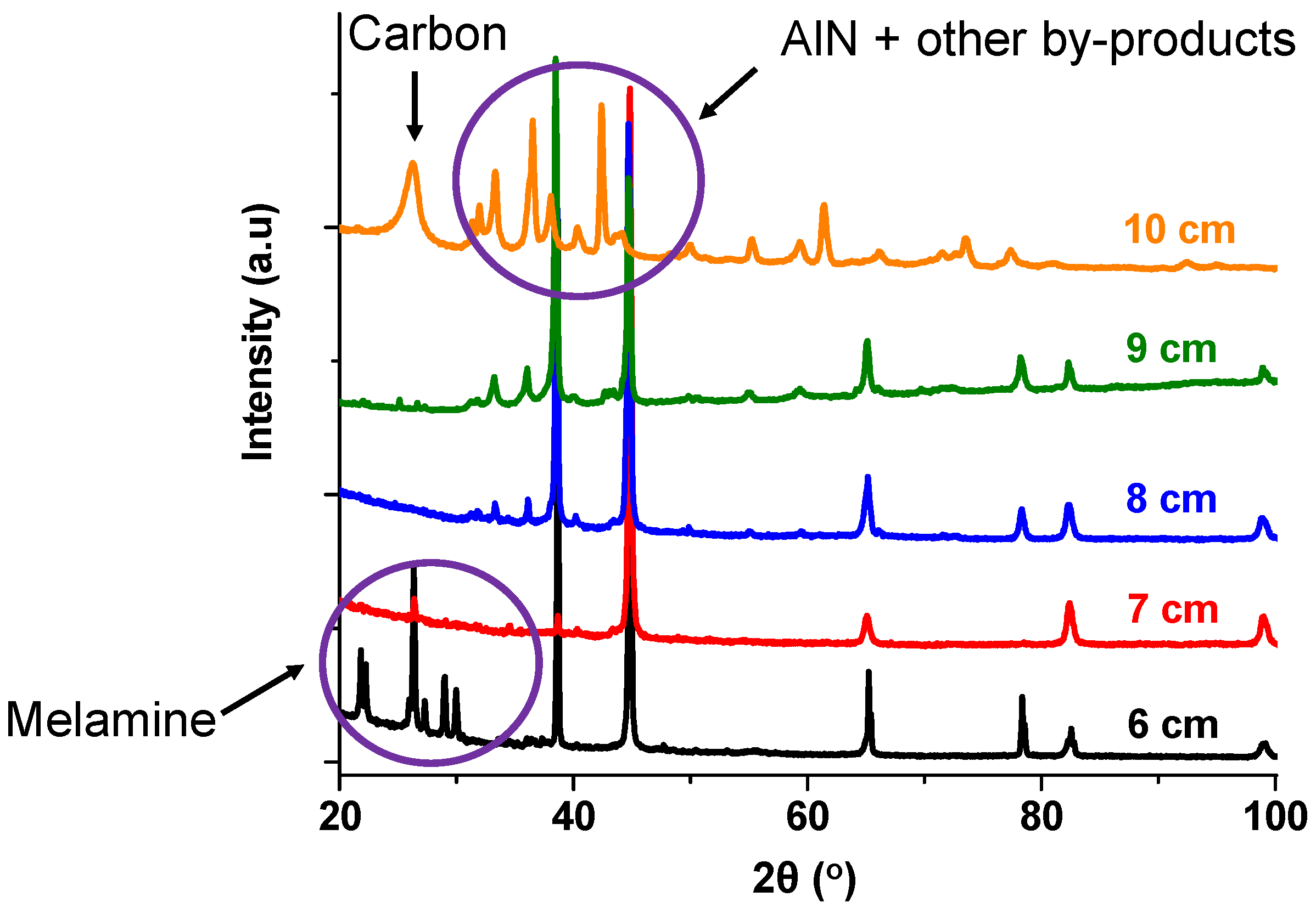
4.2. Effect of Standoff Distance on AlN Formation

In testing our hypothesis, it was postulated that the standoff distance can affect the quality of the coating. It was observed that an optimum distance destined for the maximum formation of AlN in plasma exists, which is about 8 cm as shown in Figure 9c. The XRD data from which this information was derived are provided in Figure 12. The two scenarios that were observed to influence the quality of the coating in relation to standoff distance were:
(i)
Long standoff distance: where after the nitridation, AlN failed to stick to the substrate, which was too far because either the AlN decomposed before reaching the substrate, or the AlN condensed and reached the substrate after hardening.
(ii)
Short standoff distance: characterized by low residence time in the reactor because the materials did not have enough time to react and produce AlN.
These observations imply that at a standoff distance of 8 cm, the materials have enough residence time to react during nitridation, and with high velocity at suitable particle temperature, the coatings are deposited on the substrate more effectively. At the extreme standoff distances of, for example, 10 cm there were many by products formed as shown by the many peaks in the XRD spectrum, while at a standoff distance of 6 cm the Al and melamine remained unreacted. The melamine peaks are visible below the 2θ angle of 30°.

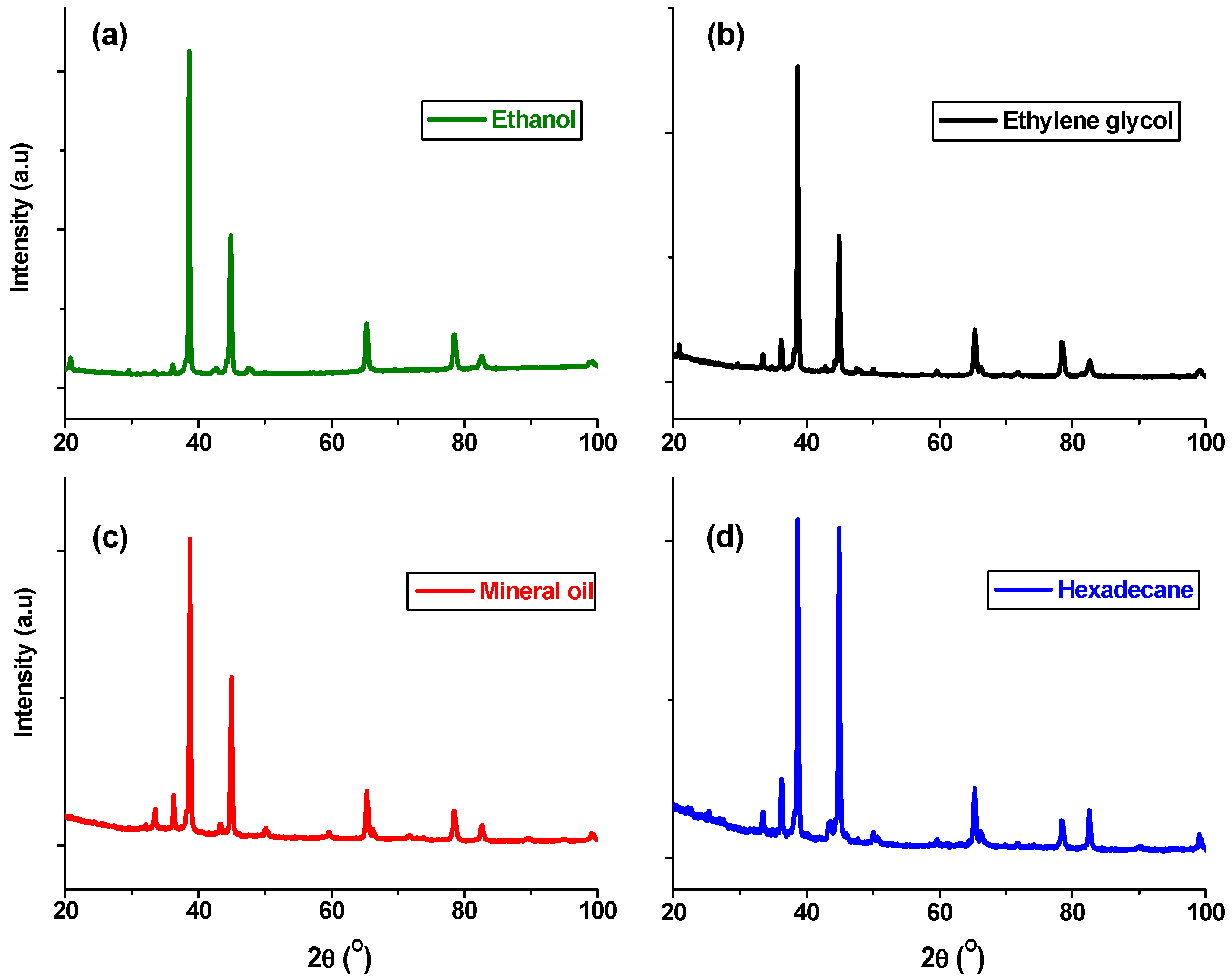
4.3. Effect of Suspension Liquids on AlN Formation

It was observed that with the application of RQA using the XRD data shown in Figure 13, utilizing hexadecane produced the highest percentage of AlN in the coatings (~82%) in comparison to using other suspension liquid carriers. Initial experiments of this project were conducted by injecting powder precursors directly into plasma. However, the difficulty with powder injection involved irregular powder flow due to high particle friction, clogging, and particle agglomeration, which led to poor coating quality. Nevertheless, by suspending the powder in an oily liquid, lubrication and therefore the smooth flow of the feedstock was enhanced. With the SPS method, we overcame the problem of irregular powder injections. Several liquids were used to create the powder suspensions, and it was observed that suspension liquids richer in oxygen (i.e., ethanol, ethylene glycol, and light mineral oil) inhibited the formation of AlN, because the oxygen preferentially reacts with Al to form Al2O3 instead of AlN.

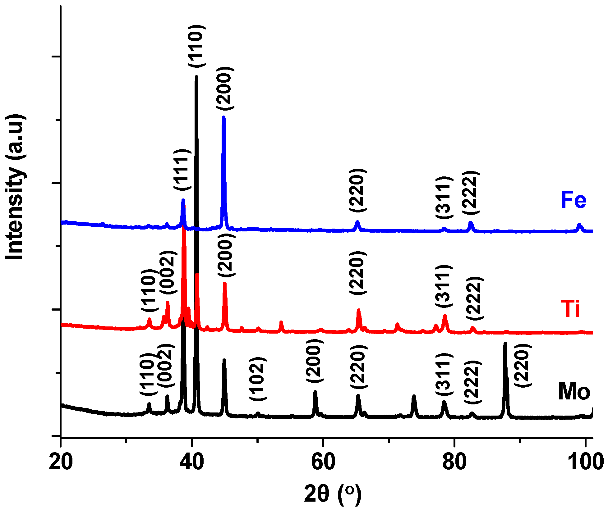
4.4. Effect of Substrate on AlN Formation

Several substrates were used to deposit the AlN coatings by SPS technology and carbon steel performed better than Mo or Ti. Their performance is related to the substrates’ thermal conductivity, whose values are 143, 54 and 24 W/m K for Mo, carbon steel and Ti, respectively [73]. We suppose that Mo with a high thermal conductivity leads to a much colder surface of the substrates that quenches the nitridation reaction. On the other hand, Ti having the lowest thermal conductivity exhibits the hottest surface temperature, which prevents the deposition of AlN. The carbon steel with a medium thermal conductivity is neither too hot nor too cold for nitridation reaction. Controlling the temperature of plasma and the substrate is therefore an important parameter in the formation of AlN coating [17]. The overlaid XRD spectra of the AlN coatings on Ti, Mo and carbon steel substrates are provided in Figure 14. Several observations were made:
(a)
The surface of the Mo substrate was exposed and detectable by XRD analysis because very little of the coating was formed.
(b)
Ti reacted with Al to produce several TiAl alloys. In addition, the AlN produced on the Ti took after the hexagonal (hcp) crystal structure of the substrates.
(c)
Carbon steel had the highest amount of cubic AlN coating, which is typical of the cubic (fcc) crystal structure of carbon steel substrate at high temperature.
(d)
Prolonged deposition periods led to the substrates overheating, consequently resulting in less AlN deposition and enhancing surface carbon formation.
Figure 15 shows the SEM images of the freshly synthesized coatings using Al powder and melamine on different substrates, where Figure 15a is for carbon steel, Figure 15b represents Ti and Figure 15c is for Mo. Although surface roughness was evident after coating deposition, the carbon steel sample comprised the highest AlN content (80% cubic phase + 2% hcp), while Mo had the least amount of AlN (15% cubic, with no hcp phase). Ti substrates consisted of 17% cubic and 13% hcp.

4.5. Materials Testing

4.5.1. Roughness and Thickness Measurements

Table 7 summarizes the results obtained from roughness and thickness tests. It was observed that surface roughness increased after the deposition of the coatings, with Mo recording the highest roughness.

4.5.2. The Wetting Test

It was observed that samples containing a high percentage of AlN demonstrated an increased contact angle as illustrated in Figure 16a. Materials with a contact angle of less than 90° are normally considered to be more hydrophilic, while those with a contact angle higher than 90° are perceived to be more hydrophobic [60]. For example, the sample containing ~82% AlN displayed a contact angle of 136° which confirms the SPS synthesized coatings is hydrophobic, while the sample with a lower quantity of AlN (~25%) displayed a decreased contact angle to 73° and it is hydrophilic as seen in Figure 16b. The measured water contact angle on PVD-deposited AlN by [74] was 119° which shows hydrophobic properties of their coatings. Furthermore, it has been observed that the contact angle between molten Al and AlN surface is 136° at 850 °C, which confirms the non-wettability of AlN by Al [55].

4.5.3. Corrosion Test

The samples with coated substrates were exposed to molten Al-Mg alloy at 850 °C for 2 h and their images depict after exposure to the molten Al alloy as shown in Figure 17.
Figure 17a–c represent the freshly plasma-synthesized coatings for Ti, carbon steel and Mo, respectively. Figure 17d–f presents the coated samples after the corrosion test for Ti, carbon steel, and Mo, respectively.
All the coated samples indicated better corrosion resistance to the hot molten alloy, and it means that the coatings provided some form of protection to the substrates. However, in the Ti and Mo based samples, the presence of AlN coating was relatively lower with significant amount of metallic Al. Some forms of islands or micro cracks were witnessed in the Ti and Mo samples, which could be related to poor thermal shock resistance. Since the coating materials are richer in metallic Al (linear thermal expansion coefficient, αL ≈ 22 ×10−6 K−1), the difference in the thermal expansion of the coatings and the substrates (Ti, αL ≈ 9 × 10⁻⁶ K−1; Mo, αL ≈ 5 × 10⁻⁶ K−1) [75], could generate some cracks in the coatings. Nevertheless, in the carbon steel sample (αL ≈ 12 × 10−6 K−1), there was less cracking on the surface of the coating, perhaps because of the enhanced presence of AlN (82%) with αL ≈ 5.3 × 10⁻⁶ K−1. However, in the Ti and Mo based samples, the presence of AlN coating was relatively lower with significant amount of metallic Al. Some forms of islands or micro cracks were witnessed in the Ti and Mo samples, which could be related to poor thermal shock resistance. As thermal resistance (Rθ) can be calculated by dividing the thickness of the samples by the product of thermal conductivity (W/m K) and cross-sectional area (m2), it was observed that the Rθ of Mo, carbon steel and Ti substrates were 0.114, 0.29 and 0.65 (K·W−1) respectively. This implies that the samples on the two extremes (either too high, that is Ti, or too low, which is Mo) performed poorly as a substrate.

5. Conclusions

AlN has attracted a lot of attention for different applications in industry due to its unique properties. In the Al industry, AlN coatings may find use when in direct contact with molten Al alloys due to their non-wetting and corrosion resistant properties. Therefore, this work proposes in situ production of AlN-rich coatings by SPS technology, which has successfully produced up to approximately 80% cubic AlN coating on a carbon steel substrate with about 2% AlN in the hexagonal phase. Temperature control for AlN synthesis is an important parameter and it is demonstrated by changing standoff distance and substrate thermal conductivity. The thermal resistance of Mo, carbon steel and Ti substrates are 0.114, 0.29 and 0.65 (K·W−1), respectively, and it was observed that the samples on the two extremes (either too high or too low) performed poorly. It suggests that surface temperature of the substrates may play a role in the production of the AlN-rich coatings, and this is influenced by both the standoff distance during spraying and the substrates’ thermal conductivity. The optimum plasma conditions included a standoff distance of 8 cm, the use of hexadecane liquid carrier, and reacting metallic Al powder with melamine as opposed to urea. Results show that favorable in situ AlN synthesis conditions by SPS include a nitrogen-rich precursor (e.g., melamine), a system without oxygen in the suspension liquid carrier (e.g., hexadecane), and depositing AlN on a carbon steel substrate.

Author Contributions

Conceptualization, F.B. and F.G.; methodology, F.B. and F.G.; software applications, F.B. and J.A.; validation, F.G. and J.A.; formal analysis, F.B. and J.A.; investigation, F.B.; writing—original draft preparation, F.B.; writing—review and editing, J.A. and F.G.; visualization, J.A.; supervision, F.G.; project administration, F.G.; funding acquisition, F.G. All authors have read and agreed to the published version of the manuscript.

Funding

This project was financially supported by the sponsorship of Pyrotek Inc., (Sherbrooke, QC, Canada) and Mitacs Accelerate (Montreal, QC, Canada).

Institutional Review Board Statement

Not applicable.

Informed Consent Statement

Not applicable.

Data Availability Statement

The data presented in this study will be publicly available in the PhD of Faranak Barandehfard (2021) at Université de Sherbrooke, which doesn’t have a DOI.

Acknowledgments

The authors would like to express their gratitude to Kossi Eyadéma Béré for technical support on the plasma system at Université de Sherbrooke. We appreciate Alain Simard, Alireza Hekmat-Ardekani, Julien Hardy, and Maxime Drolet at the Research and Development Center of Pyrotek Inc., for financial support, for providing the facilities to conduct the lab tests, the corrosion tests and optical microscopy.

Conflicts of Interest

The authors declare that there is no conflict of interest in this work. However, Pyrotek Inc., was involved in the design of the study, data collection, data analysis, providing the facilities and materials for the research and for granting the permission to publish the results. Nonetheless, they played no role in influencing the presentation or interpretation of the reported research results.

References

  1. Long, G.; Foster, L.M. Aluminum nitride, a refractory for aluminum to 2000 °C. J. Am. Chem. Soc. 1959, 42, 53–59. [Google Scholar]
  2. Yan, M.; Fan, Z. Durability of materials in molten aluminum alloys. J. Mater. Sci. 2001, 36, 285–295. [Google Scholar] [CrossRef]
  3. Iqbal, A.; Mohd-Yasin, F. Reactive sputtering of aluminum nitride (002) thin films for piezoelectric applications: A review. Sensors 2018, 18, 1797. [Google Scholar] [CrossRef] [Green Version]
  4. Oh, S.M.; Park, D.W. Preparation of AlN fine powder by thermal plasma processing. Thin Solid Films 1998, 316, 189–194. [Google Scholar] [CrossRef]
  5. Sung, M.-C.; Kuo, Y.-M.; Hsieh, L.-T.; Tsai, C.-H. Two-stage plasma nitridation approach for rapidly synthesizing aluminum nitride powders. J. Mater. Res. 2017, 32, 1279–1286. [Google Scholar] [CrossRef]
  6. Yaddanapudi, K. First-principles study of structural phase transformation and dynamical stability of cubic AlN semiconductors. AIP Adv. 2018, 8, 125006. [Google Scholar] [CrossRef] [Green Version]
  7. Kim, K. Plasma synthesis and characterization of nanocrystalline aluminum nitride particles by aluminum plasma jet discharge. J. Cryst. Growth 2005, 283, 540–546. [Google Scholar] [CrossRef]
  8. Shahien, M.; Yamada, M.; Yasui, T.; Fukumoto, M. Cubic aluminum nitride coating through atmospheric reactive plasma nitriding. J. Therm. Spray Technol. 2010, 19, 635–641. [Google Scholar] [CrossRef]
  9. Kudyakova, V.S.; Shishkin, R.A.; Elagin, A.A.; Baranov, M.V.; Beketov, A.R. Aluminium nitride cubic modifications synthesis methods and its features. Review. J. Eur. Ceram. Soc. 2017, 37, 1143–1156. [Google Scholar] [CrossRef]
  10. Jackson, T.B.; Virkar, A.V.; More, K.L.; Dinwiddie, R.B., Jr.; Cutler, R.A. High-thermal-conductivity aluminum nitride ceramics: The effect of thermodynamic, kinetic, and microstructural factors. J. Am. Ceram. Soc. 1997, 80, 1421–1435. [Google Scholar] [CrossRef]
  11. Da Cruz, A.C.; Munz, R.J. Review on the vapour-phase synthesis of aluminum nitride powder using thermal plasmas. KONA Powder Part. J. 1999, 17, 85–94. [Google Scholar] [CrossRef] [Green Version]
  12. Kim, T.-H.; Choi, S.; Park, D.-W. Effects of NH3 flow rate on the thermal plasma synthesis of AlN nanoparticles. J. Korean Phys. Soc. 2013, 63, 1864–1870. [Google Scholar] [CrossRef]
  13. Choi, S.; Im, H.; Kim, J. Synthesis of AlN particles by chemical route for theral interface material. Adv. Mater. Lett. 2017, 8, 939–943. [Google Scholar]
  14. Ahn, J.B.; Kim, D.S.; Kim, Y.K.; Lee, J.G. Synthesis of AlN particles by microwave-assisted urea route. Appl. Mech. Mater. 2016, 851, 191–195. [Google Scholar] [CrossRef]
  15. Grigoriu, C.; Hirai, M.; Nishiura, K.; Jiang, W.; Yatsui, K. Synthesis of nanosized aluminum nitride powders by pulsed laser ablation. J. Am. Ceram. Soc. 2000, 83, 2631–2633. [Google Scholar] [CrossRef]
  16. Iwata, M.; Adachi, K.; Furukawa, S.; Amakawa, T. Synthesis of purified AlN nano powder by transferred type arc plasma. J. Phys. D Appl. Phys. 2004, 37, 1041–1047. [Google Scholar] [CrossRef]
  17. Yamada, M.; Yasui, T.; Fukumoto, M.; Takahashi, K. Nitridation of aluminum particles and formation process of aluminum nitride coatings by reactive RF plasma spraying. Thin Solid Films 2007, 515, 4166–4171. [Google Scholar] [CrossRef]
  18. Shahien, M.; Yamada, M.; Yasui, T.; Fukumoto, M. Controlling of nitriding process on reactive plasma spraying of Al particles. IOP Conf. Ser. Mater. Sci. Eng. 2011, 18, 202006. [Google Scholar] [CrossRef]
  19. Choudhary, R.K.; Mishra, S.C.; Mishra, P.; Limaye, P.K.; Singh, K. Mechanical and tribological properties of crystalline aluminum nitride coatings deposited on stainless steel by magnetron sputtering. J. Nucl. Mater. 2015, 466, 69–79. [Google Scholar] [CrossRef]
  20. Belkerk, B.E.; Bensalem, S.; Soussou, A.; Carette, M.; Al Brithen, H.; Djouadi, M.A.; Scudeller, Y. Substrate-dependent thermal conductivity of aluminum nitride thin-films processed at low temperature. Appl. Phys. Lett. 2014, 105, 221905. [Google Scholar] [CrossRef]
  21. Belkerk, B.E.; Soussou, A.; Carette, M.; Djouadi, M.A.; Scudeller, Y. Structural-dependent thermal conductivity of aluminium nitride produced by reactive direct current magnetron sputtering. Appl. Phys. Lett. 2012, 101, 1–5. [Google Scholar] [CrossRef]
  22. Shahien, M.; Yamada, M.; Yasui, T.; Fukumoto, M. Synthesis of cubic aluminum nitride coating from Al2O3 powder in reactive plasma spray process. Mater. Trans. 2013, 54, 207–214. [Google Scholar] [CrossRef] [Green Version]
  23. Musa, I.; Qamhieh, N.; Said, K.; Mahmoud, S.T.; Alawadhi, H. Fabrication and characterization of aluminum nitride nanoparticles by RF magnetron sputtering and inert gas condensation technique. Coatings 2020, 10, 411. [Google Scholar] [CrossRef] [Green Version]
  24. Using, D.; Precursors, A.; Chloride, H. Aluminum nitride nanofilms by atomic layer deposition using alternative precursors hydrazinium chloride and triisobutylaluminum. Coatings 2020, 10, 195. [Google Scholar]
  25. Kim, H.H.; Lee, Y.S.; Chung, D.C.; Kim, B.J. Studies on preparation and characterization of aluminum nitride-coated carbon fibers and thermal conductivity of epoxy matrix composites. Coatings 2017, 7, 121. [Google Scholar] [CrossRef] [Green Version]
  26. Kolaklieva, L.; Chitanov, V.; Szekeres, A.; Antonova, K.; Terziyska, P.; Fogarassy, Z.; Petrik, P.; Mihailescu, I.N.; Duta, L. Pulsed laser deposition of aluminum nitride films: Correlation between mechanical, optical, and structural properties. Coatings 2019, 9, 195. [Google Scholar] [CrossRef] [Green Version]
  27. Metel, A.; Grigoriev, S.; Volosova, M.; Melnik, Y.; Mustafaev, E. Synthesis of aluminum nitride coatings assisted by fast argon atoms in a magnetron sputtering system with a separate input of argon and nitrogen. Surf. Coat. Technol. 2020, 398, 126078. [Google Scholar] [CrossRef]
  28. Gálvez, M.E.; Frei, A.; Meier, F.; Steinfeld, A. Production of AlN by carbothermal and methanothermal reduction of Al2O3 in a N2 flow using concentrated thermal radiation. Ind. Eng. Chem. Res. 2009, 48, 528–533. [Google Scholar] [CrossRef]
  29. Wu, N.C.; Tsai, M.S.; Wang, M.C.; Liu, H.S. Morphology and formation mechanism of aluminum nitride nanocrystals synthesized by chemical vapor deposition. J. Cryst. Growth 2000, 208, 189–196. [Google Scholar] [CrossRef]
  30. Jung, W.S.; Ahn, S.K. Synthesis of aluminium nitride by the reaction of aluminium sulfide with ammonia. Mater. Lett. 2000, 43, 53–56. [Google Scholar] [CrossRef]
  31. Chaundhuri, M.G. Feasibility study of synthesis of nanostructured aluminum nitride through sol-gel route. Int. J. Eng. Res. Appl. 2016, 6, 20–22. [Google Scholar]
  32. Li, P.; Xi, S.; Zhou, J. Phase transformation and gas-solid reaction of Al2O3 during high-energy ball milling in N2 atmosphere. Ceram. Int. 2009, 35, 247–251. [Google Scholar] [CrossRef]
  33. Rounaghi, S.A.; Kiani Rashid, A.R.; Eshghi, H.; Vahdati Khaki, J. Formation of nanocrystalline h-AlN during mechanochemical decomposition of melamine in the presence of metallic aluminum. J. Solid State Chem. 2012, 190, 8–11. [Google Scholar] [CrossRef]
  34. Li, C.H.; Kao, L.H.; Chen, M.J.; Wang, Y.F.; Tsai, C.H. Rapid preparation of aluminum nitride powders by using microwave plasma. J. Alloys Compd. 2012, 542, 78–84. [Google Scholar] [CrossRef]
  35. Li, L.; Hao, X.; Yu, N.; Cui, D.; Xu, X.; Jiang, M. Low-temperature solvent thermal synthesis of cubic AlN. J. Cryst. Growth 2003, 258, 268–271. [Google Scholar] [CrossRef]
  36. Kato, T.; Sugawara, K. Low-Temperature Synthesis of Aluminum Nitride by Addition of Ammonium Chloride. ACS Omega 2019, 4, 14714–14720. [Google Scholar] [CrossRef] [PubMed] [Green Version]
  37. Shahien, M.; Yamada, M.; Yasui, T.; Fukumoto, M. In situ fabrication of AlN coating by reactive plasma spraying of Al/AlN powder. Coatings 2011, 1, 88–107. [Google Scholar] [CrossRef] [Green Version]
  38. Kim, K.I.; Choi, S.C.; Kim, J.H.; Cho, W.S.; Hwang, K.T.; Han, K.S. Synthesis and characterization of high-purity aluminum nitride nanopowder by RF induction thermal plasma. Ceram. Int. 2014, 40, 8117–8123. [Google Scholar] [CrossRef]
  39. Ageorges, H.; Megy, S.; Chang, K.; Baronnet, J.M.; Williams, J.K.; Chapman, C. Synthesis of aluminum nitride in transferred arc plasma furnaces. Plasma Chem. Plasma Process. 1993, 13, 613–632. [Google Scholar] [CrossRef]
  40. Venkatramani, N. Industrial plasma torches and applications. Curr. Sci. 2002, 83, 254–262. [Google Scholar] [CrossRef]
  41. Shahien, M.; Yamada, M.; Fukumoto, M. Influence of Transient Liquid Phase Promoting Additives upon Reactive Plasma Spraying of AlN Coatings and Its Properties. Adv. Eng. Mater. 2018, 20, 1–14. [Google Scholar] [CrossRef]
  42. Qiu, Y.; Gao, L. Nitridation reaction of aluminum powder in flowing ammonia. J. Eur. Ceram. Soc. 2003, 23, 2015–2022. [Google Scholar] [CrossRef]
  43. Sun, J.F.; Wang, M.Z.; Zhao, Y.C.; Li, X.P.; Liang, B.Y. Synthesis of titanium nitride powders by reactive ball milling of titanium and urea. J. Alloys Compd. 2009, 482, 29–31. [Google Scholar] [CrossRef]
  44. Shatnawi, M.; Al-Mansi, W.; Arafa, I. Formation of Si-C-N ceramics from melamine-carbosilazane single source precursors. J. Solid State Chem. 2008, 181, 150–157. [Google Scholar] [CrossRef]
  45. Rounaghi, S.A.; Vanpoucke, D.E.P.; Eshghi, H.; Scudino, S.; Esmaeili, E.; Oswald, S.; Eckert, J. A combined experimental and theoretical investigation of the Al-Melamine reactive milling system: A mechanistic study towards AlN-based ceramics. J. Alloys Compd. 2017, 729, 240–248. [Google Scholar] [CrossRef] [Green Version]
  46. Klaus Bretterbauer, C.S. Melamine derivatives—A review on synthesis and application. Curr. Org. Synth. 2012, 9, 342–356. [Google Scholar] [CrossRef]
  47. Rounaghi, S.A.; Eshghi, H.; Scudino, S.; Esmaeili, E.; Kiani-Rashid, A.R.; Eckert, J. Mechanochemical reaction of Al and melamine: A potential approach towards the: In situ synthesis of aluminum nitride-carbon nanotube nanocomposites. Phys. Chem. Chem. Phys. 2019, 21, 22121–22131. [Google Scholar] [CrossRef]
  48. Gitzhofer, F.; Bouyer, E. Suspension Plasma Spray. U.S. Patent 5,609,921, 26 August 1997. [Google Scholar]
  49. Yamada, M.; Nakamura, H.; Yasui, T.; Fukumoto, M.; Takahashi, K. Influence of substrate materials upon fabrication of aluminum nitride coatings by reactive RF plasma spraying. Mater. Trans. 2006, 47, 1671–1676. [Google Scholar] [CrossRef] [Green Version]
  50. Cai, W.X.; Kang, L.; Wu, P.H.; Yang, S.Z.; Ji, Z.M. Fabrication of AlN thin films on different substrates at ambient temperature. Supercond. Sci. Technol. 2002, 15, 1781–1783. [Google Scholar] [CrossRef]
  51. Nogi, K.; Tomsia, A.; Eustathopoulos, N.; Mortensen, A.; Riman, R.; Milosevic, O.; Ohara, S.; Naito, M. Wettability of Solid by Liquid at High Temperature; Technical Report No. 2001MB037; Osaka University: Osaka, Japan, 2004. [Google Scholar]
  52. Sobczak, N.; Sobczak, J.; Asthana, R.; Purgert, R. The mystery of molten metal. China Foundry 2010, 7, 425–437. [Google Scholar]
  53. Fujii, H.; Nakae, H.; Okada, K. Interfacial reaction wetting in the boron nitride/molten aluminum system. Acta Metall. Mater. 1993, 41, 2963–2971. [Google Scholar] [CrossRef]
  54. Fujii, H.; Nakae, H. Equilibrium contact in the magnesium system oxide/aluminium. Acta Mater. 1996, 44, 3567–3573. [Google Scholar] [CrossRef]
  55. Mutale, C.T.; Weirauch, D.A.; Cramb, A.W. Determination of interfacial properties between AlN and aluminum beneath salt at high temperature. Mater. Sci. Eng. A 2008, 495, 60–64. [Google Scholar] [CrossRef]
  56. Cai, Y.; Coyle, T.W.; Azimi, G.; Mostaghimi, J. Superhydrophobic ceramic coatings by solution precursor plasma spray. Sci. Rep. 2016, 6, 1–7. [Google Scholar] [CrossRef] [Green Version]
  57. Barandehfard, F.; Aluha, J.; Hekmat-Ardakan, A.; Gitzhofer, F. Improving corrosion resistance of aluminosilicate refractories towards molten Al-Mg alloy using non-wetting additives: A short review. Materials 2020, 13, 4078. [Google Scholar] [CrossRef] [PubMed]
  58. Rietveld, H.M. A profile refinement method for nuclear and magnetic structures. J. Appl. Crystallogr. 1969, 2, 65–71. [Google Scholar] [CrossRef]
  59. Hild, F. Surface Energy of Plastics. Available online: https://www.tstar.com/blog/bid/33845/surface-energy-of-plastics (accessed on 14 December 2020).
  60. Majeed, M.H. Static contact angle and large water droplet thickness measurements with the change of water temperature. Coll. Eng. J. 2014, 1717, 114–128. [Google Scholar]
  61. Latthe, S.S.; Terashima, C.; Nakata, K.; Fujishima, A. Superhydrophobic surfaces developed by mimicking hierarchical surface morphology of lotus leaf. Molecules 2014, 19, 4256–4283. [Google Scholar] [CrossRef] [PubMed] [Green Version]
  62. Rounaghi, S.A.; Eshghi, H.; Scudino, S.; Vyalikh, A.; Vanpoucke, D.E.P.; Gruner, W.; Oswald, S.; Kiani Rashid, A.R.; Samadi Khoshkhoo, M.; Scheler, U.; et al. Mechanochemical route to the synthesis of nanostructured Aluminium nitride. Sci. Rep. 2016, 6, 1–11. [Google Scholar] [CrossRef] [Green Version]
  63. Mayer, I.; Schneider, S. ICDD Grant-in-Aid. Powder Diffr. J. 1987, 2. Available online: https://www.icdd.com/powder-diffraction-journal-volume-2/ (accessed on 31 March 2021).
  64. Rizolli, C.; Salamakha, S.P.; Sologub, O.L.; Bocelli, J.G. X-ray investigation of the Al–B–N ternary system: Isothermal section at 1500 °C: Crystal structure of the Al0. 185B6CN0. 256 compound. J. Alloys Compd. 2002, 343, 135–141. [Google Scholar] [CrossRef]
  65. Von Stackelberg, M.; Spiess, K.F. Die struktur des aluminiumcarbonitrids Al5C3N. Z. für Phys. Chem. 1935, 175, 140. Available online: https://www.degruyter.com/document/doi/10.1515/zpch-1935-17509/html (accessed on 31 March 2021). [CrossRef]
  66. Vollstadt, H.; Ito, E.; Akaishi, M.; Akimoto, S.; Fukunaga, O. High pressure synthesis of rocksalt type of AlN. Proc. Jpn. Acad. Ser. B 1990, 62, 7. Available online: https://www.jstage.jst.go.jp/article/pjab1977/66/1/66_1_7/_pdf (accessed on 31 March 2021). [CrossRef] [Green Version]
  67. Haglund, J.; Fernandez, F.; Grimvall, G.; Korling, M. Theory of bonding in transition-metal carbides and nitrides. Phys. Rev. B Condens. Matter Mater. Phys. 1993, 48, 11685. Available online: https://journals.aps.org/prb/abstract/10.1103/PhysRevB.48.11685 (accessed on 31 March 2021). [CrossRef] [PubMed]
  68. Huang, T.C.; Parrish, W.; Masciocchi, Ν.; Wang, P.W. Derivation of d-values from digitized X-ray and synchrotron diffraction data. Adv. X Ray Anal. 1990, 33, 295. [Google Scholar] [CrossRef]
  69. Brauer, G. Crystal structure of intermetallic alloys of aluminium with titanium, zirconium, thorium, niobium and tantalum. Naturewissenschaften 1938, 26, 14. [Google Scholar] [CrossRef]
  70. Zoriasatin, S.; Azarkharman, F.; Sebt, S.A.; Akhavan, M. Magnetic anisotropies in FeCo fine particles. J. Magn. Magn. Mater. 2006, 300, 525–531. [Google Scholar] [CrossRef]
  71. Elagin, A.A.; Beketov, A.R.; Baranov, M.V.; Shishkin, R.A. Aluminum nitride. Preparation methods (Review). Refract. Ind. Ceram. 2013, 53, 395–403. [Google Scholar] [CrossRef]
  72. Zhao, H.; Lei, M.; Chen, X.; Tang, W. Facile route to metal nitrides through melamine and metal oxides. J. Mater. Chem. 2006, 16, 4407–4412. [Google Scholar] [CrossRef]
  73. Engineering ToolBox. Thermal Conductivity of Metals, Metallic Elements and Alloys. 2005. Available online: https://www.engineeringtoolbox.com/thermal-conductivity-metals-d_858.html (accessed on 31 March 2021).
  74. Yang, Y.S.; Cho, T.P. Effect of annealing temperature on the water contact angle of PVD hard coatings. Materials 2013, 6, 3373–3386. [Google Scholar] [CrossRef]
  75. Engineering ToolBox. Coefficients of Linear Thermal Expansion. 2003. Available online: https://www.engineeringtoolbox.com/linear-expansion-coefficients-d_95.html (accessed on 31 March 2021).
Figure 1. Dynamic contact angles at the interfaces of a moving droplet for (a) water on PTFE and (b) ethylene glycol on PTFE.
Coatings 11 00500 g001
Figure 2. Thermodynamics plots showing the potential of producing AlN from melamine through plasma synthesis.
Coatings 11 00500 g002
Figure 3. Modelling by FactSage™ showing the limited potential of producing AlN from urea through plasma.
Coatings 11 00500 g003
Figure 4. (a) A SEM image of AlN coating produced from melamine on the carbon steel substrate in X500 magnification; (b) the mixed EDX elemental mapping of Al and N; (c,d) individual elemental mapping of Al and N, and (e) EDX spectrum.
Coatings 11 00500 g004
Figure 5. A top surface view by SEM imaging for plasma-synthesized AlN-rich coating on carbon steel in ×15,000 magnification.
Coatings 11 00500 g005
Figure 6. Cross sectional view of the AlN-rich coating on carbon steel by SEM imaging in ×2500 magnification.
Coatings 11 00500 g006
Figure 7. XRD patterns with the two major peaks used to identify AlN in the coatings, showing (a) AlN peaks; and (b) metallic Al peaks.
Coatings 11 00500 g007
Figure 8. A typical result from the Rietveld quantitative analysis of a plasma synthesized sample.
Coatings 11 00500 g008
Figure 9. Calculated amount of AlN% in the coatings by RQA using XRD data where (a) shows the impact of different substrates; and by using carbon steel substrate, (b) the effect of nitriding agents; (c) different standoff distances and (d) the suspension liquid was studied.
Coatings 11 00500 g009
Figure 10. XRD patterns of in situ produced coatings in plasma by the reaction between Al powder and the two nitriding agents: (a) urea and (b) melamine.
Coatings 11 00500 g010
Figure 11. SEM imaging of AlN coating derived from Al and urea on Ti substrate in X5000 magnification, indicating its (a) secondary electron image; (b) EDX spectrum; and (cf) EDX elemental mapping for N, Al, Ti, O, respectively.
Coatings 11 00500 g011
Figure 12. XRD patterns revealing the optimum distance for depositing AlN on carbon steel substrate using melamine and Al powder in hexadecane.
Coatings 11 00500 g012
Figure 13. XRD patterns of coatings produced from Al powder and melamine in different suspension media: (a) ethanol, (b) ethylene glycol, (c) mineral oil and (d) hexadecane.
Coatings 11 00500 g013
Figure 14. XRD patterns of coatings produced from Al and melamine on different substrates.
Coatings 11 00500 g014
Figure 15. SEM images of coatings produced from Al powder and melamine on different substrates: (a) carbon steel, (b) Ti and (c) Mo, in ×20,000 magnification.
Coatings 11 00500 g015
Figure 16. How the presence of AlN in a material improves its non-wetting properties, (a) a coating with 82% AlN shows contact angle of 136°, and (b) a coating with 25% AlN shows contact angle of about 73°.
Coatings 11 00500 g016
Figure 17. Optical microscopic images of the plasma synthesized coatings for (a) Ti, (b) carbon steel and (c) Mo; the coated samples after corrosion test for (d) Ti, (e) carbon steel and (f) Mo.
Coatings 11 00500 g017
Table 1. Selected AlN properties.
PropertiesValues
Thermal expansion coefficientα = 4.3 × 10⁻⁶ K−1
Thermal conductivityk = 319 W·m−1·K−1
Crystalline structureHexagonal or cubic
Hardness1400 Hv
Electrical resistivity1013 Ω·cm
Band gap6.2 eV
Table 2. Summary of different methods used in producing AlN coatings.
MethodPrecursorsCoating SubstrateReference
RF plasma sprayAl powder + N2stainless steel, quartz plate[17]
DC plasma sprayAl powder + NH4Clmild steel (SS400)[18]
Atmospheric plasma spraying (APS)Al powder + N2 + H2soft steel (SS400)[8]
Magnetron sputteringAl-disc + Ar + N2stainless steel (SS) 304L[19]
LT reactive magnetron sputteringAl powder + Ar + N2crystal Si, amorphous SiN[20]
Reactive DC magnetron sputteringAl powder + Ar + N2crystal Si, amorphous SiN[21]
Reactive plasma sprayAl2O3 + N2mild steel (SS400)[22]
RF magnetron sputteringAlN + Arglass, mica, and silicon[23]
Atomic layer depositionAl(C4H9)3 + N2H5Cl + C12H27Alsilicon[24]
Wet-thermal treatment (WTT)NH3 + N2 + AlCl3carbon fiber[25]
Pulsed laser depositionAlN + N2Si (100)[26]
Magnetron sputtering systemAl + N2silicon nitride[27]
RF = Radio frequency; DC = Direct current; LT = Low temperature.
Table 3. Summary of different methods used for producing AlN powder.
MethodPrecursorsReference
Carbothermal reductionAl2O3 + N2 + C/CH4[28]
CVDAlCl3 + NH3 + N2[29]
Reaction 500–1000 °C for 5 hAl2S3 + NH3[30]
Sol-gelC9H21O3Al + dextrose[31]
MechanochemicalAl2O3 powder + N2[32]
MechanochemicalAl powder + Melamine[33]
Transferred Arc-plasmaAl powder + N2 + NH3[16]
Microwave plasmaAl powder + NH4Cl + N2 + H2[34]
Solvent thermal synthesisAlCl3 + NaN3[35]
Low-temperature synthesisAl + NH4Cl[36]
Reactive plasma sprayAl + AlN powders[37]
CVD = Chemical vapor deposition; LT = Low temperature.
Table 4. Reaction conditions for the in situ production of plasma-synthesized AlN coatings.
Process ConditionParametersValue
Plasma systemPower system40 kW
Plasma torchTekna PL-50 (3.2MHz)
Plasma gas flow rate (SLPM)Sheath gasAr: 52, H2: 5.5, N2: 40
Central gasAr: 22
Atomization gasAr: 10
Reactor pressureInitial pressureBelow 2 kPa
Working Pressure16 kPa
Suspension flow rateFlow2.0 mL·min−1
Standoff distanceDistance8.0 cm
SubstrateTi, Mo, Carbon steel12.7 mm × 2.0 mm
Suspension composition:
(a)
Suspension = Precursor + Liquid
(b)
Precursor = (Al + melamine) or (Al + urea)
Suspension liquid: Ethanol, Ethylene glycol, Hexadecane, light mineral oil100 mL
Precursor concentration5, 10, 20 g in 100 mL
Al powder1.0 g
Melamine9.0 g
Urea13 g
Concentration (precursor: liquid)e.g., 10 g: 100 mL
Number of loopsDeposition cycles200
Table 5. A summary of the atomic percentage of each element in coatings sprayed on carbon steel, Ti and Mo substrates as calculated by EDX.
SubstratesElements (Atomic-%)
AlNO
Carbon steel413524
Titanium553015
Molybdenum502228
Table 6. Measured amount of the various phases in the plasma-synthesized coatings by RQA using XRD data.
Synthesis ParametersPhase Concentration in the Coatings (%)
Cubic-AlNhcp-AlNAlAl4C3Others
SubstratesCarbon steel802104.53.5% amorphous
Ti171350-18% Ti3Al2% TiAl3
Mo15-62-23% Mo
Suspension liquidsEthylene glycol131270-1% Al2O34% Fe5C2
Ethanol-585 10% carbon-
Hexadecane802104.53.5% amorphous
Light mineral oil221660-2% FeN
Standoff distance6 cm10-28-60% Melamine2% amorphous
7 cm20-5-5% Carbon70% Fe
8 cm802104.53.5% amorphous
9 cm27154682% Fe2% Fe3C
10 cm-3521540% Carbon8% Fe3O4
Nitriding agentUrea25-65-10% TiAl-
Melamine802104.53.5% amorphous
Table 7. Surface roughness measurements of substrates and coatings.
SubstratesRa Values (µm)Coating Thickness (µm)
Before CoatingAfter Coating
Carbon steel0.543 ± 0.022.703 ± 0.4~20–40
Titanium0.388 ± 0.032.215 ± 0.3~20–30
Molybdenum0.515 ± 0.034.034 ± 0.6~15–20
Publisher’s Note: MDPI stays neutral with regard to jurisdictional claims in published maps and institutional affiliations.

