Review

Langmuir Probe Technique for Plasma Characterization during Pulsed Laser Deposition Process

by
Stefan Andrei Irimiciuc
1,*,
Sergii Chertopalov
2,
Jan Lancok
2 and
Valentin Craciun
1,3,*
1
National Institute for Laser, Plasma and Radiation Physics–NILPRP, 409 Atomistilor Street, 077125 Bucharest, Romania
2
Institute of Physics of the Czech Academy of Sciences, Na Slovance 2 1999/2, 182 00 Prague, Czech Republic
3
Extreme Light Infrastructure for Nuclear Physics, IFIN-HH, 077125 Magurele, Romania
*
Authors to whom correspondence should be addressed.
Coatings 2021, 11(7), 762; https://doi.org/10.3390/coatings11070762
Submission received: 25 May 2021 / Revised: 21 June 2021 / Accepted: 22 June 2021 / Published: 25 June 2021

Abstract

:
The history of pulsed laser deposition (PLD) and transient plasmas generated by laser ablation is intertwined with the development of various techniques for its fundamental understanding. Some diagnostic tools have been developed to better suit the rapid transient nature of the plasma (space and time dependence of all parameters, fast decay and complex chemistry inside the plasma), whereas others have been adapted from basic plasma physics studies. Langmuir probe method has been used as a real-time in situ diagnostic tool for laser ablation and later for PLD. It remains a useful tool for the PLD community arsenal, which can easily be adapted to the development of new lasers and ablation regimes and new deposition configuration, being one of the most versatile techniques for plasma diagnostics. It is the cornerstone on which charge particles are analyzed and has led to several important discoveries, such as multiple peak distribution, selective acceleration during expansion, plume splitting, plasma turbulences and fluctuations. However, because the Langmuir probe theory adaptation from classical plasma physics is not straightforward, it might lead to misinterpretation and often incorrect analysis of data. This review analyzes the limits and understanding of the technique as a foundation for attaining its full potential, which can impact the way PLD is used. This is especially useful for the pressing need of real-time, in-situ diagnostics and feedback loops for systematic semi-industrial implementation of the PLD technique.

1. Introduction: A History of Measurements

Laser ablation is defining a sequence of fundamental processes seen as the outcome of laser beam irradiation of a solid surface. The effects of light interaction with the matter have been identified and reported on for centuries. Some reports from Greek literature dating from 303 B.C. describe a water-filled globe with a special property that can produce fire in various conditions. An ancient view on the concept of “photonic ablation” can be found in the writings of Archimedes, who in 203 B.C. suggested the use of an array of mirrors to reflect and focus the sunlight on the Phoenicians fleet [1].
The beginning of laser ablation as a modern research direction started with a series of conference papers and talks in the 1960s. There were reports on a wide range of fundamental aspects that will eventually grow into pillars of laser ablation and laser-produced plasmas on which a completely new research direction was created. The first scientific paper was a fundamental (theoretical) study of Askaryan and Moroz [2], and contained calculations regarding the recoil pressure resulting from ablating a solid target by promoting the scenario of small particles and droplets acceleration by developing what was named at the time as the “one-sided evaporation” model. Similar pioneering work was done by Honig and Woolston [3], reporting on laser ablation of a wide range of materials (metals, semiconductors and dielectrics), giving the first quantitative data on the amount of particles removed by laser ablation: 3 × 10¹⁶ electrons and 108 positive ions per m3; coupled with a detailed study of electron emission temporal profile. The ablated mass distribution was also investigated with a tailored double-focusing mass spectrometer, proving the first use of ion microprobe analysis. These results later became the foundation for ion mass spectrometry and created the need for electrical investigations of laser-produced plasmas (LPPs). Lichtman and Ready [4], in the framework of thermionic emission assumption, calculated the surface temperature during laser irradiation of solid targets, reporting values of 3.3 × 10³ K for a ruby laser pulse interacting with a W target. Ready [5] reported for the first time on the use of fast-gated photography as an appropriate technique to investigate the evolution (by means of temporal and spatial profiles) of the ejected particle plume. One of the main results of that study was that the LPP optical emission reached a maximum emission at 120 ns with respect to the laser-target interaction moment and had a lifetime of a few μs expanding with an average velocity of 20 km/s. Subsequent investigations on carbon-based targets were reported by Howe [6], who derived the ejected particle energy in the framework of a non-equilibrium plasma environment ascribed to particle cooling during an adiabatic expansion. Further exploration of the subject was seen in the work of Berkowitz and Chupka [7], who reported on the generation of carbon (n 14), boron (n 5) and manganese (n 2) clusters after post-ionization of the ejected plasma plume. The production of large structures during laser ablation can be found in other reports [8] being described as large “blobs of molten material” or “fragments of material” analyzed by the first momentum transfer measurements. The few results mentioned here were part of a large movement predominantly focused on laser-produced plasma diagnostics. These fundamental studies have expanded over a vast range of laser beam properties (wavelength, pulse width, beam power, repetition rate, beam shape etc.). The implementation of a series of new and diverse methods such as visible or ultra-violet, and X-ray emission measurements [9,10], coupled with the findings of multiply-charged ions [11] and two- and three-photon emission [12] and associated findings led to the development of new applications based on laser ablation and laser-matter interaction.
In 1964, for the first time, Berkowitz and Chupka [7] promoted the idea of a fusion alternative based on laser ablation called laser confinement fusion. Another notable application is pulsed laser deposition (PLD), developed as an alternative to the already existing deposition techniques (sputtering and thermal evaporation). The first pure PLD experiment was reported by Smith and Turner [13]. At the time the thin films developed by PLD were inferior to the ones deposited by sputtering and thermal evaporation. Dijkkamp et al. [14] reported on the first high-quality film deposited by PLD. They deposited high-quality thin film of YBa2Cu3O7 which could not have been produced through other alternative techniques. Following this, the PLD technique has been successfully implemented for the manufacturing of thin films with a wide range of properties (ceramic oxides, nitrides, metallic multilayers with high crystallinity) [15,16,17]. One of the most notable advantages of PLD are the lower costs, when compared with molecular beam epitaxy (MBE) or metal-organic chemical vapor deposition (MOCVD), and improved control over stoichiometry, phase and thin film composition. This control is essential for the growth of complex multi-element materials, including high-quality nanomaterials with stoichiometries that cannot be achieved otherwise. Noteworthy successes of PLD can be summarized by the nature of the resulting deposit (nanowires of Si and Ge [18]), binary (In2O3 [19], SnO2 [19,20], ZnO [21]) or ternary systems (GaAs0.6P0.4, InAs0.5P0.5, CdSxSe1−x, indium tin oxide [22,23]), and more complex materials [24]. As thin film technology developed, seminal work was published by Voievodin’s group [25,26,27,28] with the main focus on carbonaceous structure formation during PLD of diamond-like films. The same extraordinary insight into pulsed laser deposition was seen in the work of Grigoriev et al. [29] where experimental data was combined with numerical simulation to investigate complex thin films generated in various atmospheric conditions. In the recent years, through the work of Giuffredi et al. [30,31] and Fominski et al. [32], it was shown that plasma monitoring with ion probes can be a successful approach for in-situ analysis during formation of complex films. The real-time monitoring during the deposition process was extended to other techniques like magnetron sputtering [33,34], PECVD [35] or plasma spray [36,37].
With the advancements in thin-film technology, the growing reliability and stability of commercial lasers (Q-switched YAG or excimer lasers), translated to the improvement of thin film uniformity and long-range reproducibility of microprobe measurements. Noteworthy progress was made, on the fundamental mechanism of the deposition process. PLD is a complex process with existing correlations between target physical properties (melting point, vaporization temperature, electrical conductivity, etc.), laser characteristics (fluence, wavelength, repetition rate, pulse width), background gas species (molecular, atomic inert or reactive), substrates’ physical properties and the PLD ensemble geometry. All these parameters are in an unstable equilibrium, and changing one parameter might shift the ideal settings for others. Due to this web of inter-relationships, the control of the deposition process becomes difficult and is directly correlated with knowledge of the LPP dynamics and the effect of the plasma plume properties on the deposited film. If we analyze the deposition process from different angles based on the nature of some influencing factors, this complicated image of PLD can be somehow simplified. One aspect is related to the interactions between the laser beam and the target, defined by the physical properties of the target (reflectivity, electrical conductivity, heat of vaporization, mass etc.) and those of the laser beam (wavelength, pulse width, shape, fluence, etc.) [9,38]. A second aspect covers the relationships between the physical properties of the irradiated sample and those of the laser produced plasmas [39,40] and the last one covers the impact of the ablated cloud on the properties of the thin film. To gain some insights into any of these relationships it is required to implement well-established plasma diagnostic techniques (Langmuir probe (LP), electrostatic analyzer, fast gated photography (ICCD fast camera imaging), optical emission spectroscopy (OES) or mass spectrometry, etc.) to attempt unification relations amongst all these variables.
The effort put into fundamental investigation of LPP translated in important discoveries. Plume splitting was first reported by Geohegan’s group [41,42] when investigating the expansion of carbon LPP in an ambient gas. The same group proposed several theoretical models based on multiple-scattering and hydrodynamic approaches [43] to understand the behavior of LPP. Confirmation of the plume splitting paradigm was given by other groups [44,45,46]. All the reports were focused on plasmas generated experimental conditions comparable with the PLD experiments (i.e., fluences: 1–2 J/cm2 and background gas pressure: 1–100 mbar). We note here that similar results were also reported for extreme conditions: vacuum (background pressure <10−5 mbar) and at high fluences above 10 J/cm2 [47]. From a theoretical standpoint plume splitting is a phenomenon that can be induced by the hydrodynamic heterogeneity amongst the groups of particles ejected by means of distinct mechanisms [48]: the ions are removed on a very short time scale through a Coulomb explosion in the very intense field caused by the electron depletion by laser excitation and detachment, while the neutrals are ejected via subsequent thermal process like explosive boiling which reportedly requires more time to establish [48].

2. Classical Theory of Langmuir Probe Adapted for Transient Plasmas
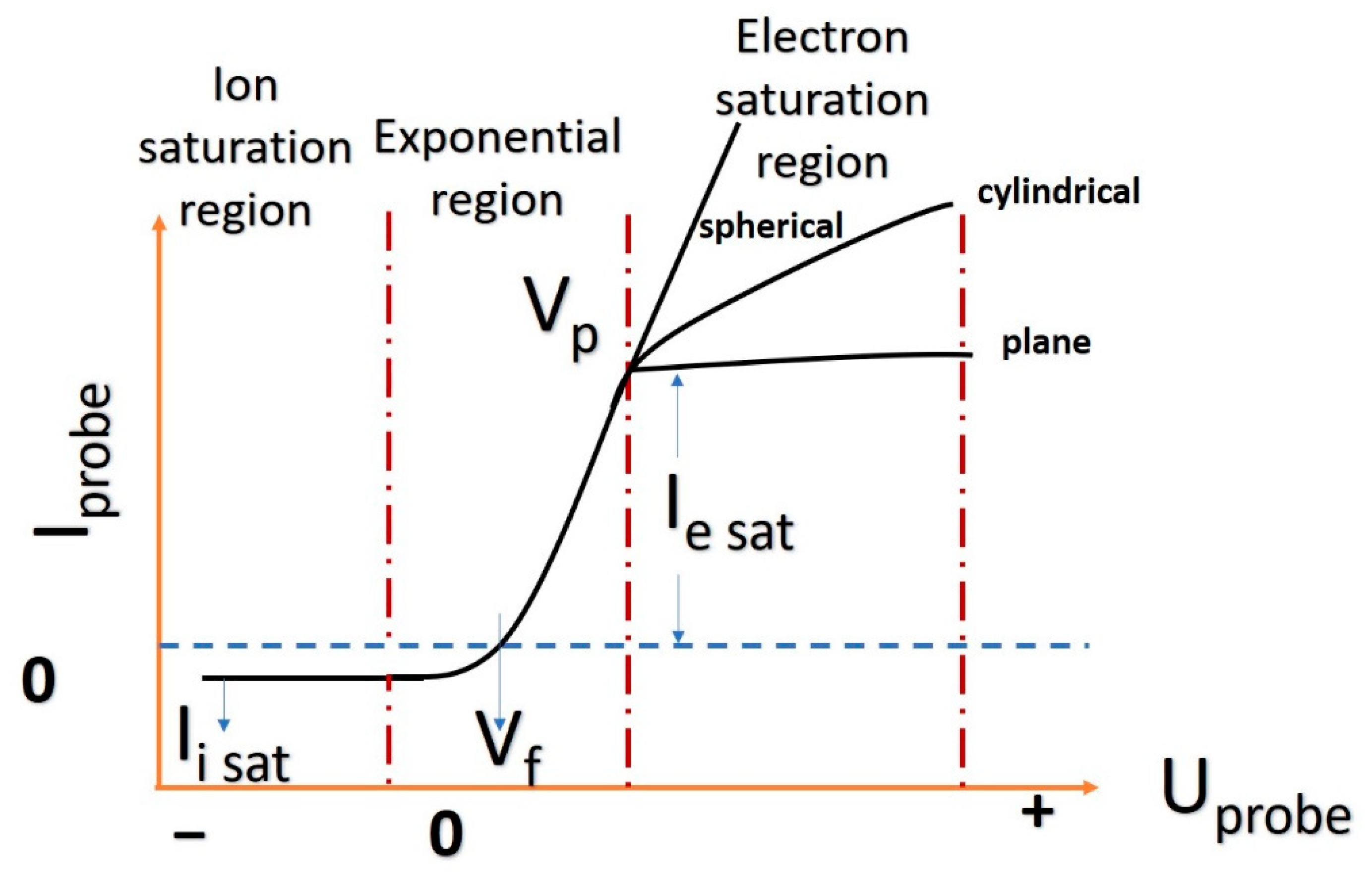
Historically the Langmuir probe (LP) method was first proposed by Langmuir [35] in order to facilitate the description of ionized gases. Both the theory and the technical aspects surrounding this experimental technique have evolved over time [49,50,51,52,53]. Nowadays the Langmuir probe presents great versatility; it is used on various types of plasmas based on different technologies (laser-produced plasma, discharge plasma, fusion or sputtering plasmas) as well as in various geometrical configurations [54,55,56] (single probe: planar, cylindrical, spherical (Figure 1), double or triple probe). It has been accepted as one of the main techniques for plasma investigations. The dynamics of the plasma particles (ions and electrons) in the vicinity of the probe do not differ fundamentally from one probe configuration to another; consequently no major difference will appear in the LP theory variants corresponding to different geometrical configurations. In the following section, we will briefly describe the dynamics of the electrons and ions in the vicinity of the probe and show how this can lead to the determination of a series of basic plasma parameters (temperature, density, plasma potential and velocity).
Let us consider the case of an ideal stationary plasma (i.e., neutral from an electric point of view, homogeneous and presenting local or global thermodynamic equilibrium). When the probe (a metallic electrode, for simplicity we will consider it plane) is immersed inside the plasma, the electrons, ions and neutral atoms will arrive at the probe location due to the movement imposed by the drift, thermal velocities and probe-biased voltage. Given the difference between the masses of the electrons and the ions, the number of electrons per time unit that will initially arrive at the probe surface will be larger than that of ions, and thus will negatively charge the probe surface. As a result, a surface potential is formed where the electrons will be slowed down and rejected, while the ions will be accelerated towards the probe. Within this surface, the plasma neutrality is broken and there are no secondary ionizations. In this stationary regime, the overall number of electrons will be equal to that of the ions. This can be written as the equality between the two fluxes:
j e = 1 4 e n e v e ; j i = 1 4 e n i v i
with ne, ni being the charged particles number densities and υe, and υi being the velocities with which the particles reach the probe.
When the probe is biased, either positively or negatively, an electrical field is generated around the probe. As such, only one type of particle will pass towards the probe, while the other is repelled. The “collecting” area from the plasma is defined by the value of the applied voltage and the density of the plasma. Generally, this is called a space charge surface, and it can spread on a few Debye lengths. The Debye length defines a minimum volume for which properties like plasma neutrality and local thermodynamic equilibrium are satisfied. The space charge is described by the Child relation:   D = λ Debye 2 3 ( 2 e V k T e ) 3 4 , where D describes the thickness of the plasma sheet where the electron density is negligible, and   λ Debye = k T e ε 0 n e e 2 . The role of the applied voltage is not only to differentiate between different types of charges, but also to separate them based on their energy. Thus, by sweeping a wide enough range, one would be able to collect all electrons and ions. If we take into account the simplest case, that of the planar configuration, the condition necessary to extract a particle from the plume is related to the kinetics of the incoming particles: kinetic energy of the particle (the component oriented towards the probe surface) is higher than the space charge surface field e ( V Plasma V Pr obe ) , with V Plasma the plasma potential and V Pr obe the voltage applied on the probe. Therefore, the nature of the collected charge (and thus the probe current) is decided by the polarization of the probe. For a positive potential, all the electrons are collected, and due to their Maxwell-Boltzmann velocity distribution, the final relationship describing the electron current is:
I Pr obe = I ( V Pr obe ) = I e I i = I e 0 exp [ e ( V Plasma V Pr obe ) k T e ] I i 0 , V Pr obe < V Plasma ,
while for a negative potential
I Pr obe = I e 0 I i 0 exp [ e ( V Pr obe V Plasma ) k T i ] , V Pr obe > V Plasma ,
where IProbe is the current collected by the probe, Ie and Ii are the electronic and ionic currents, respectively, Ie0 and Ii0 are the respective saturation currents, e is the electron charge, k is the Boltzmann constant, Te is the electron temperature and Ti is the ion temperature.
While the bias voltages are swept from high negative values to their corresponding positive ones, a characteristic similar to the ones presented in Figure 2 is obtained. This is called the I-V (current-voltage) characteristic. Although the shape of the characteristic is slightly dependent on the geometry of the probe, we can typically identify three different regions:
a)
The saturation ionic region is defined by a small current amplitude and a relatively fast saturation for the ionic current. The saturation current is defined as I i 0 = A e n i T e 2 π m i (where A is the probe area, e is the electron charge, ni is the ionic density, Te the electron temperature and mi the ionic mass);
b)
The transition part, where the floating potential (Vf) can be found as the voltage for which the current on the probe equals zero, is followed by an exponential increase of the electronic current. The inflection point of the characteristic, where the current changes from an exponential dependence on the VProbe to a squared root one, will define the plasma potential VPlasma;
c)
The saturation electronic region is defined by a maximum electronic current collected by the probe. The saturation current is defined as I e 0 = A e n e T e 2 π m e . This region is particularly characteristic to the planar probe, whereas for other configurations the electron saturation is not reached. This is due to the increase of the space charge surface around the LP.
Figure 3 shows a series of characteristic signals for an Al plasma (Figure 3a) and angular measurements using an un-biased probe (Figure 3b). The Al plasma [57] was generated by fs-laser ablation using a Ti:Sa femtosecond laser beam (λ = 800 nm, 60 fs, 1.7 mJ/pulse, 100 Hz) at a laser fluence of 8.5 J/cm2 while the Ag plasma [58] was generated by a Continuum Surelite III Nd:YAG laser (λ = 266 nm, 81 mJ, 5 ns, 10 Hz) operated at a fluence of 3.8 J/cm2. The I-V characteristic can be reconstructed at different moments of time, allowing for the treatment of the laser ablation plasma at specific moments as being a homogeneous, stationary plasma, with a local (partially) thermodynamic equilibrium. Given these assumptions, some bottlenecks are identified. At short times during expansion, when the plasma plume has a small volume, the active surface of the LP can be significantly large with respect to the plasma volume and the theoretical treatment of the LP is not valid since the measurement should not significantly affect the plasma. Consequently, most LP measurements [53,56] are performed at long distances from the target (typically a few cm) and at long evolution times (after 1 μs). This is understandable as the plume increases its volume as it evolves, with the collecting area changing accordingly as it is related to the plasma density. To overcome this limitation alternative implementations of the probe are required. Our group has proposed a new approach by introducing an unbiased probe scenario. Time-series for a non-biased probe (floating measurement regime) extracted from an Ag plasma [58] are presented in Figure 3b. When the probe is unbiased, the focus of the measurement is on the drift movement and the kinetic energy of the flowing plasma. The lack of a selective bias voltage allows the particle to reach the probe based on their mass-energy ratio. We noticed that electrons arrive first on the probe and are followed by the main groups of ions. The advantage of this approach is the ability to differentiate between different elements or ionic species of the same element in a single measurement, while the classical approach sums all the contributions offering an overall view of the plasma.
Once the I-V characteristic is obtained, there are other plasma parameters that can be identified. By reducing the ionic current and representing the evolution of the electron current as a function of the applied bias voltage in a logarithmic scale (Figure 4a,b), further determination of the electron temperature, the plasma potential and subsequently particle densities, the thermal velocities and the Debye length can be performed. When investigating the time resolved analysis of electron temperature in vacuum conditions (10−6 Pa) we noticed two different slopes in the logarithmic representation of the I-V curve. This result highlights the presence of two generations of electrons with different temperatures (hot and cold-hot and cold nomenclature is used relative to the two groups of electrons). The result is in line with the paradigm centered on the two-temperature model often used, although it lacks strong empirical proof from a LP theory point of view. Some literature reports [59,60] discuss the presence of two electronic groups when implementing the LP current interpretation to target current measurements. They perform a linear fit on both the linear increase which would characterize the Te and the saturation region which is not supported by the LP theory. The Te-hot decreases exponentially and becomes negligible at long evolution times, while the Te-cold has a more complex distribution. Te-cold has a three-peak evolution with each peak characterizing the three plasma structures reported via non-biased probe measurements (see Figure 4c). The plasma potential ha a similar evolution with the one of the cold electrons which implies that the dominant group in the framework of PLD are the cold electrons. We would also like to underline here that this two-temperature dynamic is only seen in ultra-high vacuum conditions and for short evolution times. At longer times there is a contribution only from the cold electrons in the plasma. Equations (1)–(3) are used to determine the main plasma parameters (Te and Vp) and show that the temporal evolution is not a monotonous one. Moreover, charge particle densities and characteristic values for plasma can be found, such as Debye sphere diameter, ion oscillation frequency, collision cross-section or charge state [56].
On the particularities of the technique there has been an impressive effort from groups all over the world to clarify and implement it for the specific nature of LPPs. The combined efforts of the groups of Amoruso, Lunney, Schou and Lippert [47,52,61,62,63] have been of paramount importance in the development and implementation of the technique for LPPs and for fundamental studies of such plasmas. Wood et al. [43] presented an astute analysis of the time-of-flight signal and LP method for plasmas generated on metallic and dielectric targets expanding a wide series of gases. The group of Focsa [57,59,64] extended the implementation for plasmas generated on metals by fs and ps lasers showing an important flexibility and scalability of the technique. The work of Torrisi et al. [65] and Krasa et al. [66] highlighted the temporal distribution of charge particles extracted from LPP’s offering a fundamental theoretical and empirical background for their interpretation.

3. Time-of-Flight Analysis of Charge Fluxes in LPP

By considering the properties of transient plasmas generated by laser ablation for which all properties present spatial and temporal evolution, the time-sampling method can have certain limitations. For the case of LPP, the current time-of-flight trances I = f (t) are directly correlated with the velocity distribution of the ejected particles, by means of υ = d/t, where t is the arrival time of the particle at the probe and d is the target-probe distance [50]. This is an approach that is developed in the approximation of constant kinetic energy of the ejected particles. This approximation is supported (for LPP expansion under vacuum) by experimental observations [67,68,69] and theoretical reports. In a report by Kelly [70], there is a model developed for particle expansion in the vicinity of the target. Based on this model each particle experiences several collisions leading to the formation of a Knudsen layer, and a subsequent supersonic expansion [71]. The Knudsen layer transforms the “half-range” (υz > 0, with z axis along the normal to the target) velocity distribution present at the sample surface into a “full-range” (−∞ < υz < +∞) Coulomb shifted Maxwell distribution, based on the υdrift. In this paradigm, the time-dependence of the probe signal is given by [72]:
I i ( t ) 1 t n exp [ m i 2 k b T i ( d t v drift ) 2 ] .
Equation (4) describes the saturation current temporal traces, as depicted in Figure 5a where the current time-of-flight (TOF) profile of a Cu plasma (Ti:Sa femtosecond laser beam (800 nm, 60 fs, 1.7 mJ/pulse, 100 Hz) at a laser fluence of 8.5 J/cm2) for a probe bias of −10 V was fitted. It is apparent that a clear deconvolution is needed for the floating potential measurements, as the plasma is distinctly separating in multiple structures defined by different drift velocities. The structuring of the plasma is not an artefact of the measuring technique but it is a natural feature of the plasma. Several reports using complementary methods like fast camera imaging, TOF mass spectrometry and time-resolved optical emission spectroscopy covered this subject.
Alternative interpretations of the TOF signal are given in the literature (see [56,73,74]), where it was considered that the movement of the charged particle “cloud” is defined by its “average” velocity υaverage, derived as d/tmax, where tmax (see Figure 5) is the arrival time of the maximum ionic current (associated with the most probable velocity in a Boltzmann velocity distribution representation). We also stress here that this is a limiting approach as this velocity is a global one and disregards the inner structuring of the plasma when applied to the saturation current. The charge current is then defined as
I i , e = e A n i , e v average
This view over the measurement allows for the determination of the charge density distributions with the velocity in all points of the plasma volume (see Figure 6 for an Ag plasma generated by ns-laser ablation in Ar and O2 gases). This approach implemented to the un-biased measurements can offer information about the kinetics of each ionic and electronic structure. Our group recently reported some feature of the charge density distribution induced by gas ionization during Ag plasma expansion in Ar gas and on complex angular distribution of the Ag ions velocities in a reactive gas.
The nature of the ionic velocity is often correlated with the fundamental interactions within the plasma volume and/or with the ejection mechanism and thermodynamical properties of the expanding cloud. This approach was used by Torisi et al. [75] when reporting on ion kinetics in LPPs.
The real image of the overall contributions to particle dynamic during plasma expansion is more complex. In LPP the contributions to ejected particle velocity are threefold: thermal, free expansion and Coulomb-driven. This means that at any time a particle can be described by three possible movements. The thermal movement of the charged particle is best covered by LP theory as the core development of the probe is based on the quasi-static movement of ions and thermal movement of electrons. These extreme conditions are satisfied when implementing time-sampling of the ionic and electronic current as each slice represents a snapshot of the plasma. The free expansion component is best described by the thermal mechanism of ablation and particles can be described as an adiabatic expansion of a hot gas of particles. This view is reflected in LPP models and can give the information about the ion TOF trace and angular distribution with a high degree of confidence. Finally, the Coulomb-driven component is the second component of the drift movement and regards the charge separation that occurs in the first stage of plasma expansion where intense accelerating voltages can be applied on small volumes (Debye surfaces) and induces acceleration of the charges based on the ionized state and mass. If we reconsider Equation (4) in this expanding paradigm and revisit the Coulomb-shifted Maxwellian velocity function [76,77]:
F ( v th , v ad , v c ) = A ( m 2 π k T ) 3 / 2 e [ ( m 2 k T ) ( v th v ad v c ) 2 ]
where v th , v ad , v c are the thermal velocity, free expansion velocity and the Coulomb velocity components, respectively, T is the plasma temperature, k is the Boltzmann constant, A is a normalization constant, m is the ion mass. Each velocity component can be given by the analytical relations:
v th = 3 k T m , v ad = γ k T m , v c = 2 z e V 0 m
where γ is the adiabatic coefficient, z is the charge state, e is the electron charge, and V 0 is the accelerated voltage developed at the edges of the double layer in the nonequilibrium plasma. This description of the charged particle kinetic energy means that both average velocity and drift one as defined in Equations (4) and (5) are actually composed by the superposition of v ad and v c . Defining plasma temperature in the framework presented through Equations (6) and (7) creates an equivalent of the usual definition of the plasma temperature as it is understood in the context of the LP theory. From the classical approach the plasma temperature is given by the thermal movement of the electrons and is more a measure of the electron thermal movement. The temperature equivalent can be determined semi-empirically according to [77] by considering the laser beam power density as the main source of thermal energy of the plasma:
k T = 100 ( I 10 17 [ W / cm 2 ] ) 1 / 3 [ e V ]
where kT is the equivalent plasma temperature and is derived from the laser pulse intensity I. If the plasma temperature is known, let us propose an alternative route for Debye length determination. Let us consider the ablation yield as a measure of neutral density in the plasma. For 1 μg/pulse according to [76] we can ablate 3.3 × 10¹⁵ atoms/pulse, which gives a 1017 cm−3 density of neutrals. The value is similar to other reports of ionic densities found in plasmas which offer a range of 1015–1017 cm−3. In similar conditions the fractional ionization can be as high as 20–30% and the average ionization state 2+. Assuming local thermodynamic equilibrium in the vicinity of the probe where the measurements are performed and an electron density of 1016 cm–3, the relation defining the Debye length at times comparable with the laser pulse is:
λ Debye = 69 ( T n 0 ) 1 / 2   [ m ]
where T is plasma temperature in Kelvin and n 0 in m–3. For these values the Debye length corresponds to approximately 1.2 μm. From here a small step can be done towards estimating the electrical field generated in the vicinity of the target. The acceleration field that would induce the separation in ion probe current and lead to multiple maxima in the TOF ion temporal trace is
E = V 0 λ Debye   [ V m ]

4. Limitation for Langmuir Probe Method: Perturbative Regimes and Misinterpretation of Fluctuations in the Plasma

The flexibility of the LP can be easily seen in terms of implementation and the information extracted from the plasma with relationship to the fundamentals of laser ablation or to the PLD as a technological process. As we mentioned in the previous sections the technique is not universally applicable and has strong limitations that need to be taken into account. These limitations can be divided into two main categories: development (geometry and implementation) and perturbative processes.
The development limitations are all in relationship with the implementation of the time-swiping method which is used for the determination of localized time-evolution of a wide series of parameters. The probe should not actively intervene in the natural processes occurring in the plasma. Therefore, the dimension of the active region of the probe needs to be calibrated with the measuring distance. The essential characteristic of the LPP is its transient nature. This means that the dimensions and properties of the measured plasma volume will constantly change during the lifetime of the plasma. This aspect was thoroughly investigated and highlighted through ICCD fast camera imaging of LPP expanding in various gasses [78]. An actual understanding of the LPP evolution is that the plasma will increase its volume while losing particles, thermal and kinetic energy. It is important to stress here that the geometry of the plasma is also altered by the presence of the substrate [79] which can confine the movement of the charged particles and alter the overall shape of the plasma or by changing the charged particles dynamics through electric or magnetic fields [80] during the PLD process. The dimensions of the probe will affect the collecting surface that will interfere with the plasma and thus can influence and perturb the free dynamics of the particles. This limitation excludes the implementation of the probe at a few mm from the target where it will strongly interact with the small (mm sized plasma) high-density, high-energy plasma. Reports show charges with hundreds of eV up to a few keV leaving the target. Even with Debye length of a few μm (often reported for laser-produced plasmas) the collecting area can be tens or hundreds of μm. These values correspond to percentages between 1% and 10% from the whole volume of the plasma, which potentially could make the measurements unreliable.
If the dimensions of the probe are considerably smaller than the overall plasma volume and the measuring distance is relatively large (>1–2 cm) then the probe can offer information with a higher confidence degree. If this is ensured, let us focus on the next possible limitation regarding the perturbative mode of the probe. Nonlinear effects could occur at the probe surface and can be induced by the high energy of the incoming ions that could lead to probe sputtering and possible contamination of the deposition process. To date, no proof of probe sputtering or traces of thin film contamination during in-situ real-time measurements has been reported in the literature. However, if the working gas pressure is increased, proper conditions for other nonlinear phenomena can be reached. Similar behaviors were found in reports of positively-biased electrodes immersed in Ar plasma at different pressures (>2 Pa). According to reports from the group of Dimitriu [81], self-organized single or multiple structures named plasma fireball are generated on the surface of the electrode. The oscillations result from the disruption and reformation of the double layer formed around the fireball with ionic species being ejected in the plasma from the ion rich core of the fireball. Proof of similar behavior seen on LP immersed in an Ag plasma expanding in Ar is presented in Figure 7. This result is of great importance for LP measurements and their general limitation when implemented for in-situ and real-time monitoring of PLD process, especially considering the relatively large measuring distance (37 mm), the relatively low bias applied on the probe (4–20 V) and the PLD conditions (5–10 Pa–Ar gas). Based on our data we can generalize that at elevated Ar pressure conditions, for biases higher than 4 V, a fireball-like structure with a short lifetime is formed on the probe surface, and thus LP becomes perturbative for the deposition process. Similar behaviors were seen for a variety of metallic plasmas in the same range of Ar pressure.
These oscillations seen in the 0–2 μs time range are induced by the Ar plasma generated by the ionization and excitations of the LPP, and therefore are not a physical process within the plasma. The problem with ionic oscillations in LPP has been amply discussed in a series of paper starting from 1987 up to as recently as 2021. One of first reports of charge particle oscillations in laser-produced plasmas was published in the 1980s. Borowitz et al. [82] reported fast oscillating of about 100 ps period on the current induced in a metallic target when irradiating with a 100 J, ns laser beam (fluence up to 105 J/cm2). The interpretation was that the waves in the current are induced by the plasma, however the plasma expands and has a clear density and spatial limitation, thus recoil particles returning on the surface from the plasma expanding with 10 and 100 km/s seems unlikely. There are some reports attempting to explain this strange behavior. The consensus is that the formation of single or multiple double layer vicinity of the target leads to a wave-like structure in the charge current temporal traces. This problem was the core focus in a series of papers mainly from 1970–1980 [83,84,85] reporting on charge separation during the expansion of laser-produced plasma. Eliezer and Hora [86] published a collection of paper where they built the state of the art on the double and multiple layers in LPPs. Some reported data provided empirical proof for the existence of double-layer electric fields of 105–106 V/cm and widths of 10–100 Debye lengths [64]. We would like to stress that they address only the behavior in the first 1–2 mm from the target. The modern view of particle kinetics is that the charged particles are accelerated in the double layer and thus a separation based on mass–charge ratio occurs leading to multiple maxima in ion flux measurement. This was successfully used to describe multi-element plasmas and explain charged particle acceleration during the flow of plasma in high-vacuum conditions.
The study of ionic and electronic oscillations in LPPs was revisited in recent years with many reports on the presence of an oscillatory regime in the ionic current during the early stages of ablation (<1 μs). There are reports on the unusual effects in LPP (double and multiple layer formation, or oscillations) as results of systematic experimental studies of plasma plumes generated by laser ablation in various temporal regimes (ns, ps, fs) on materials spanning from simple metals (Cu, Al, Mn, Ni, W, Te, In, Zn, Ti, etc.) to more complex compounds (ceramics, chalcogenide glasses, ferrites) [87,88,89,90] were performed. The reported values for what are presented as ionic oscillations vary and their frequencies range from tens or hundreds of kHz up to GHz. This would imply that within the plasma volume there are waves of charged particles moving on distances of a few μm up to a few cm according to their drift velocity. These values do not correspond to their equivalent in Debye lengths. Alternatively, if these millimetric movements are occurring, they should have been observed by ICCD camera imaging or time resolved optical emission spectroscopy, which again there is no proof. The only plausible data is for ionic oscillations with frequencies of the order of GHz which can be sustained in the plasma volume. However, this would correspond to electronic oscillations of THz order which to this date have not been reported.
A series of models based in a fractal framework were developed in [67] as the interaction between two structures projected in a multifractal space, and their corresponding interface (associated with the delimitation of the double layer [90]). Others are developed in a collisional model based on the plasma ion frequency and electron-ion collision rate [87] in the framework of the Lieberman’s model for plasma immersion ion implantation, or a model based on the AC Josephson effect [87]. In parallel, other groups have reported oscillatory behaviors of plasma temperature and plasma potential by implementing double and triple probe. It is worth noting that although the results h confirm an oscillatory movement of the plasma, it mostly refers to the movement of the electrons. As we presented earlier, all the information regarding the electron temperature, plasma density Debye length, etc. are directly related with the electron movement during plasma expansion. Let us reiterate that in understanding of the LP theory the movement of the ions is neglected and the source of information becomes the electrons. GHz oscillations of the plasma electrons in a low-temperature plasma are plausible for a constant Debye length. In laser-produced plasma the spatial region where the oscillations could occur changes as the plasma expands, so the oscillatory movement cannot be separated by the drift movement of the electrons and possible heterogeneity in the energy distribution of set charges. The experimental data is not disputed here but rather it interpreted as waves or fluctuations in a highly energetic fast-expanding plasma with pure plasma oscillations, which can be problematic.

5. Conclusions

An overview of the Langmuir probe theory and its implementation for transient plasmas generated by ns and fs laser ablation was presented. The time sampling approach, which is essential in time resolved electrical investigations is presented in extenso and details on determining a wide range of parameters are given. The time series analysis is also presented in two variants: a semi-empirical one and a theoretical one based on the shifted Maxwell–Boltzmann distribution. An alternative to ionic saturation current measurement is proposed here in the form of non-biased probe measurements which has the advantage of measuring the flow of the particles induced by drift movement. Finally, some limitations and the perturbative regime of the probe are discussed. The geometrical and construction limitations are fraught with shortcomings in the interpretation of the probe current in extreme conditions, where sputtering, non-linear effects or even particle rebound from the probe surface can be seen.

Author Contributions

Conceptualization, S.A.I.; methodology, S.A.I. and S.C.; investigation, S.A.I. and S.C.; resources, J.L. and V.C.; writing-original draft preparation, S.A.I., V.C., J.L. and S.C.; writing-review and editing, S.A.I., V.C., J.L. and S.C.; visualization, S.A.I. and S.C.; supervision, J.L. and V.C.; funding acquisition, J.L., S.A.I. and V.C. All authors have read and agreed to the published version of the manuscript.

Funding

This work was supported by Czech Science Foundation (GAČR) by project No. 20-21069S and by Romanian Ministry of Education and Research, under Romanian National Nucleu Program LAPLAS VI–contract n. 16N/2019, ELI-RO_2020_12 project and Postdoctoral Project PD 145/2020. We acknowledge the Operational Program Research, Development and Education financed by European Structural and Investment Funds and the Czech Ministry of Education, Youth and Sports SOLID21 CZ.02.1.01/0.0/0.0/16_019/0000760.

Institutional Review Board Statement

Not applicable.

Informed Consent Statement

Not applicable.

Data Availability Statement

Data will be available upon request from the corresponding author.

Conflicts of Interest

The authors declare no conflict of interest.

References

  1. Miller, C.J. Laser Ablation; Miller, C.J., Ed.; Springer: Berlin/Heidelberg, Germany, 1994; Volume 28, ISBN 978-3-642-78722-5. [Google Scholar]
  2. Askar’yan, G.A.; Moroz, E.M. Pressure on evaporation of matter in a radiation beam. Sov. Phys. 1963, 13, 1638–1639. [Google Scholar]
  3. Honig, R.E.; Woolston, J.R. Laser-induced emission of electrons, ions, and neutral atoms from solid surfaces. Appl. Phys. Lett. 1963, 2, 138. [Google Scholar] [CrossRef]
  4. Lichtman, D.; Ready, J.F. Laser beam induced electron emission. Phys. Rev. Lett. 1963, 10, 342–345. [Google Scholar] [CrossRef]
  5. Ready, J.F. Development of plume of material vaporized by giant-pulse laser. Appl. Phys. Lett. 1963, 3, 11–13. [Google Scholar] [CrossRef]
  6. Howe, J.A. Observations on the maser-induced graphite. Jet. J. Chem. Phys. 1963, 39, 1362–1363. [Google Scholar] [CrossRef]
  7. Berkowitz, J.; Chupka, W.A. mass spectrometric study of vapor ejected from graphite and other solids by focused laser beams. J. Chem. Phys. 1964, 40, 2735–2736. [Google Scholar] [CrossRef]
  8. Neuman, F. Momentum transfer and cratering effects produced by giant laser pulses. Appl. Phys. Lett. 1964, 4, 167–169. [Google Scholar] [CrossRef]
  9. Benavides, O.; de la Cruz May, L.; Mejia, E.B.; Ruz Hernandez, J.A.; Flores Gil, A. Laser wavelength effect on nanosecond laser light reflection in ablation of metals. Laser Phys. 2016, 26, 126101. [Google Scholar] [CrossRef]
  10. Ehler, A.W.; Weissler, G.L. Vacuum ultraviolet radiation from plasmas formed by a laser on metal surfaces. Appl. Phys. Lett. 1966, 8, 89. [Google Scholar] [CrossRef]
  11. Archbold, E.; Hughes, T.P. Electron temperature in a laser-heated plasma. Nature 1964, 204, 670. [Google Scholar] [CrossRef]
  12. Sonnenberg, H.; Heffner, H.; Spicer, W. two-photon photoelectric effect in Cs3Sb1. Appl. Phys. Lett. 1964, 5, 95–96. [Google Scholar] [CrossRef]
  13. Smith, H.M.; Turner, A.F. Vacuum deposited thin films using a ruby laser. Appl. Opt. 1965, 4, 147. [Google Scholar] [CrossRef]
  14. Dijkkamp, D.; Venkatesan, T.; Wu, X.D.; Shaheen, S.A.; Jisrawi, N.; Min-Lee, Y.H.; McLean, W.L.; Croft, M. Preparation of Y-Ba-Cu oxide superconductor thin films using pulsed laser evaporation from high Tc bulk material. Appl. Phys. Lett. 1987, 51, 619–621. [Google Scholar] [CrossRef]
  15. Eason, R. Pulsed Laser Deposition of Thin Films: Applications-Led Growth of Functional Materials; John Wiley & Sons: New York, NY, USA, 2007; ISBN 0471447099. [Google Scholar]
  16. Itina, T. Laser Ablation From fundamentals to Applications; In Tech Open: Rijeka, Croatia, 2017; ISBN 978-953-51-3700-9. [Google Scholar]
  17. Loiseleur, P.; Hansen, T.N.; Larour, J.; Lunney, J.G. Time-resolved EUV spectroscopy in the early stage of laser ablation of carbon. Appl. Surf. Sci. 2002, 197–198, 164–168. [Google Scholar] [CrossRef]
  18. Morales, L. A laser ablation method for the synthesis of crystalline semiconductor nanowires. Science 1998, 279, 208–211. [Google Scholar] [CrossRef]
  19. Liu, Z.; Zhang, D.; Han, S.; Li, C.; Tang, T.; Jin, W.; Liu, X.; Lei, B.; Zhou, C. Laser ablation synthesis and electron transport studies of tin oxide nanowires. Adv. Mater. 2003, 15, 1754–1757. [Google Scholar] [CrossRef]
  20. Sotelo, J.G.; Bonilla-Ríos, J.; García-Escobar, F.; Gordillo, J.L. Film growth of tetragonal SnO2 on glass substrate by dip-coating technique for ethanol sensing applications. Coatings 2021, 11, 303. [Google Scholar] [CrossRef]
  21. Marra, A.; Rollo, G.; Cimmino, S.; Silvestre, C. Assessment on the effects of ZnO and Coated ZnO particles on iPP and PLA properties for application in food packaging. Coatings 2017, 7, 29. [Google Scholar] [CrossRef] [Green Version]
  22. Savu, R.; Joanni, E. Low-temperature, self-nucleated growth of indium–tin oxide nanostructures by pulsed laser deposition on amorphous substrates. Scripta Mat. 2006, 55, 979–981. [Google Scholar] [CrossRef]
  23. Craciun, V.; Craciun, D.; Wang, X.; Anderson, T.J.; Singh, R.K. Highly conducting indium tin oxide films grown by ultraviolet-assisted pulsed laser deposition at low temperatures. J. Optoelectron. Adv. Mat. 2003, 5, 401–408. [Google Scholar] [CrossRef]
  24. Eisenhawer, B.; Zhang, D.; Clavel, R.; Berger, A.; Michler, J.; Christiansen, S. Growth of doped silicon nanowires by pulsed laser deposition and their analysis by electron beam induced current imaging. Nanotechnology 2011, 22, 075706. [Google Scholar] [CrossRef]
  25. Pappas, D.L.; Saenger, K.L.; Cuomo, J.J.; Dreyfus, R.W. Characterization of laser vaporization plasmas generated for the deposition of diamond-like carbon. J. Appl. Phys. 1992, 72, 3966–3970. [Google Scholar] [CrossRef]
  26. Voevodin, A.A.; Donley, M.S. Preparation of amorphous diamond-like carbon by pulsed laser deposition: A critical review. Surf. Coat. Technol. 1996, 82, 199–213. [Google Scholar] [CrossRef]
  27. Voevodin, A.A.; Jones, J.G.; Zabinski, J.S.; Hultman, L. Plasma characterization during laser ablation of graphite in nitrogen for the growth of fullerene-like CNx films. J. Appl. Phys. 2002, 92, 724–735. [Google Scholar] [CrossRef]
  28. Voevodin, A.A.; Laube, S.J.P. In situ plasma monitoring of pulsed laser deposition of diamond-like carbon films. Surf. Coat. Technol. 1995, 76–77, 670–674. [Google Scholar] [CrossRef]
  29. Grigoriev, S.N.; Fominski, V.Y.; Gnedovets, A.G.; Romanov, R.I. Experimental and numerical study of the chemical composition of WSex thin films obtained by pulsed laser deposition in vacuum and in a buffer gas atmosphere. Appl. Surf. Sci. 2012, 258, 7000–7007. [Google Scholar] [CrossRef]
  30. Giuffreda, E.; Delle Side, D.; Nassisi, V.; Krása, J. Plasma production in carbon-based materials. Nucl. Instrum. Methods Phys. Res. Sect. B Beam Interact. Mater. Atoms 2017, 406, 225–228. [Google Scholar] [CrossRef]
  31. Krása, J.; Delle Side, D.; Giuffreda, E.; Nassisi, V. Characteristics of target polarization by laser ablation. Laser Part. Beams 2015, 33, 601–605. [Google Scholar] [CrossRef] [Green Version]
  32. Fominski, V.; Demin, M.; Fominski, D.; Romanov, R.; Goikhman, A.; Maksimova, K. Comparative study of the structure, composition, and electrocatalytic performance of hydrogen evolution in mosx~2+δ/mo and mosx~3+δ films obtained by pulsed laser deposition. Nanomaterials 2020, 10, 201. [Google Scholar] [CrossRef] [Green Version]
  33. Salimian, A.; Hasnath, A.; Anguilano, L.; Onwukwe, U.; Aminishahsavarani, A.; Sachez, C.; Upadhyaya, H. Highly conductive zinc oxide based transparent conductive oxide films prepared using RF plasma sputtering under reducing atmosphere. Coatings 2020, 10, 472. [Google Scholar] [CrossRef]
  34. Salimian, A.; Haghpanahan, R.; Hasnath, A.; Upadhyaya, H. Optical analysis of RF sputtering plasma through colour characterization. Coatings 2019, 9, 315. [Google Scholar] [CrossRef] [Green Version]
  35. Hsieh, Y.L.; Kau, L.H.; Huang, H.J.; Lee, C.C.; Fuh, Y.K.; Li, T.T. In situ plasma monitoring of PECVD nc-Si:H Films and the influence of dilution ratio on structural evolution. Coatings 2018, 8, 238. [Google Scholar] [CrossRef] [Green Version]
  36. Song, J.B.; Kim, J.T.; Oh, S.G.; Yun, J.Y. Contamination particles and plasma etching behavior of atmospheric plasma sprayed Y2O3 and YF3 coatings under NF3 plasma. Coatings 2019, 9, 102. [Google Scholar] [CrossRef] [Green Version]
  37. Zhang, Y.; Mack, D.E.; Mauer, G.; Vaßen, R. Laser cladding of embedded sensors for thermal barrier coating applications. Coatings 2018, 8, 176. [Google Scholar] [CrossRef] [Green Version]
  38. Zavestovskaya, I.N.; Glazov, O.A.; Demchenko, N.N. Threshold characteristics of ultrashort laser pulse ablation of metals. Proc. 3rd Int. Conf. Front. Plasma Phys. Technol. 2008, 3, 10–18. [Google Scholar]
  39. Hermann, J.; Mercadier, L.; Axente, E.; Noël, S. Properties of plasmas produced by short double pulse laser ablation of metals. J. Phys. Conf. Ser. 2012, 399, 012006. [Google Scholar] [CrossRef]
  40. Williams, G.O.; O’Connor, G.M.; Mannion, P.T.; Glynn, T.J. Langmuir probe investigation of surface contamination effects on metals during femtosecond laser ablation. Appl. Surf. Sci. 2008, 254, 5921–5926. [Google Scholar] [CrossRef]
  41. Geohegan, D.B.; Puretzky, A.A. Dynamics of laser ablation plume penetration through low pressure background gases. Appl. Phys. Lett. 1995, 67, 197–199. [Google Scholar] [CrossRef] [Green Version]
  42. Geohegan, D.B.; Puretzky, A.A. Laser ablation plume thermalization dynamics in background gases: Combined imaging, optical absorption and emission spectroscopy, and ion probe measurements. Appl. Surf. Sci. 1996, 96–98, 131–138. [Google Scholar] [CrossRef] [Green Version]
  43. Leboeuf, J.N.; Chen, K.R.; Donato, J.M.; Geohegan, D.B.; Liu, C.L.; Puretzky, A.A.; Wood, R.F. Modeling of dynamical processes in laser ablation. Appl. Surf. Sci. 1996, 96–98, 14–23. [Google Scholar] [CrossRef] [Green Version]
  44. Harilal, S.S.; Bindhu, C.V.; Tillack, M.S.; Najmabadi, F.; Gaeris, A.C. Plume splitting and sharpening in laser-produced aluminium plasma. J. Phys. D Appl. Phys. 2002, 35, 2935–2938. [Google Scholar] [CrossRef] [Green Version]
  45. Harilal, S.S.; Bindhu, C.V.; Tillack, M.S.; Najmabadi, F.; Gaeris, A.C. Internal structure and expansion dynamics of laser ablation plumes into ambient gases. J. Appl. Phys. 2003, 93, 2380–2388. [Google Scholar] [CrossRef] [Green Version]
  46. Wu, J.; Li, X.; Wei, W.; Jia, S.; Qiu, A. Understanding plume splitting of laser ablated plasma: A view from ion distribution dynamics. Phys. Plasmas 2013, 20, 113512. [Google Scholar] [CrossRef]
  47. Amoruso, S.; Toftmann, B.; Schou, J. Broadening and attenuation of UV laser ablation plumes in background gases. Appl. Surf. Sci. 2005, 248, 323–328. [Google Scholar] [CrossRef]
  48. Yoo, J.H.; Jeong, S.H.; Mao, X.L.; Greif, R.; Russo, R.E. Evidence for phase-explosion and generation of large particles during high power nanosecond laser ablation of silicon. Appl. Phys. Lett. 2000, 76, 783. [Google Scholar] [CrossRef]
  49. Lahm, S.H. Unified theory of langmuir probe in a collisionless plasma. Phys. Fluids 1965, 8, 73. [Google Scholar] [CrossRef]
  50. Koopman, D.W. Langmuir probe and microwave measurements of the properties of streaming plasmas generated by focused laser pulses. Phys. Fluids 1971, 14, 1707. [Google Scholar] [CrossRef]
  51. Merlino, R.L. Understanding Langmuir probe current-voltage characteristics. Am. J. Phys. 2007, 75, 1078. [Google Scholar] [CrossRef] [Green Version]
  52. Lunney, J.G.; Doggett, B.; Kaufman, Y. Langmuir probe diagnosis of laser ablation plasmas. J. Phys. Conf. Ser. 2007, 59, 470–474. [Google Scholar] [CrossRef]
  53. Donnelly, T.; Lunney, J.G.; Amoruso, S.; Bruzzese, R.; Wang, X.; Ni, X. Dynamics of the plumes produced by ultrafast laser ablation of metals. J. Appl. Phys. 2010, 108, 043309. [Google Scholar] [CrossRef] [Green Version]
  54. Ovsyannikov, A.A.; Zhukov, M.F. Plasma Diagnostics; Cambridge International Science Publishing: Cambridge, UK, 2000. [Google Scholar]
  55. Chen, F.F. Introduction to Plasma Physics; Springer: Boston, MA, USA, 1974; pp. 1–16. [Google Scholar]
  56. Doggett, B.; Lunney, J.G. Langmuir probe characterization of laser ablation plasmas. J. Appl. Phys. 2009, 105, 033306. [Google Scholar] [CrossRef]
  57. Irimiciuc, S.A.; Gurlui, S.; Bulai, G.; Nica, P.; Agop, M.; Focsa, C. Langmuir probe investigation of transient plasmas generated by femtosecond laser ablation of several metals: Influence of the target physical properties on the plume dynamics. Appl. Surf. Sci. 2017, 417, 108–118. [Google Scholar] [CrossRef]
  58. Irimiciuc, S.A.; Chertopalov, S.; Craciun, V.; Novotný, M.; Lancok, J. Investigation of laser-produced plasma multistructuring by floating probe measurements and optical emission spectroscopy. Plasma Process. Polym. 2020, 17, 2000136. [Google Scholar] [CrossRef]
  59. Focsa, C.; Gurlui, S.; Nica, P.; Agop, M.; Ziskind, M. Plume splitting and oscillatory behavior in transient plasmas generated by high-fluence laser ablation in vacuum. Appl. Surf. Sci. 2017, 424, 299–309. [Google Scholar] [CrossRef]
  60. Nica, P.; Agop, M.; Gurlui, S.; Bejinariu, C.; Focsa, C. Characterization of aluminum laser produced plasma by target current measurements. Jpn. J. Appl. Phys. 2012, 51, 106102. [Google Scholar] [CrossRef]
  61. Anoop, K.K.; Polek, M.P.; Bruzzese, R.; Amoruso, S.; Harilal, S.S. Multidiagnostic analysis of ion dynamics in ultrafast laser ablation of metals over a large fluence range. J. Appl. Phys. 2015, 117, 083108. [Google Scholar] [CrossRef] [Green Version]
  62. Donnelly, T.; Lunney, J.G.; Amoruso, S.; Bruzzese, R.; Wang, X.; Ni, X. Angular distributions of plume components in ultrafast laser ablation of metal targets. Appl. Phys. A Mater. Sci. Process. 2010, 100, 569–574. [Google Scholar] [CrossRef]
  63. Amoruso, S.; Schou, J.; Lunney, J.G.; Phipps, C. Ablation plume dynamics in a background gas. In AIP Conference Proceedings; American Institute of Physics: Melville, NY, USA, 2010; pp. 665–676. [Google Scholar]
  64. Irimiciuc, S.; Boidin, R.; Bulai, G.; Gurlui, S.; Nemec, P.; Nazabal, V.; Focsa, C. Laser ablation of (GeSe2)100−x(Sb2Se3)x chalcogenide glasses: Influence of the target composition on the plasma plume dynamics. Appl. Surf. Sci. 2017, 418, 594–600. [Google Scholar] [CrossRef]
  65. Caridi, F.; Torrisi, L.; Margarone, D.; Borrielli, A. Investigations on low temperature laser-generated plasmas. Laser Part. Beams 2008, 26, 265–271. [Google Scholar] [CrossRef]
  66. Krása, J.; Lorusso, A.; Doria, D.; Belloni, F.; Nassisi, V.; Rohlena, K. Time-of-flight profile of multiply-charged ion currents produced by a pulse laser. Plasma Phys. Control. Fusion 2005, 47, 1339–1349. [Google Scholar] [CrossRef]
  67. Gurlui, S.; Agop, M.; Nica, P.; Ziskind, M.; Focsa, C. Experimental and theoretical investigations of a laser-produced aluminum plasma. Phys. Rev. E 2008, 78, 026405. [Google Scholar] [CrossRef]
  68. Focsa, C.; Nemec, P.; Ziskind, M.; Ursu, C.; Gurlui, S.; Nazabal, V. Laser ablation of AsxSe100−x chalcogenide glasses: Plume investigations. Appl. Surf. Sci. 2009, 255, 5307–5311. [Google Scholar] [CrossRef]
  69. Ursu, C.; Gurlui, S.; Focsa, C.; Popa, G. Space and time-resolved optical diagnosis for the study of laser ablation plasma dynamics. Nucl. Instruments Methods Phys. Res. Sect. B Beam Interact. with Mater. Atoms 2009, 267, 446–450. [Google Scholar]
  70. Kelly, R.; Dreyfus, R.W. On the effect of Knudsen-layer formation on studies of vaporization, sputtering, and desorption. Surf. Sci. 1988, 198, 263–276. [Google Scholar] [CrossRef]
  71. Mihesan, C.; Lebrun, N.; Ziskind, M.; Chazallon, B.; Focsa, C.; Destombes, J.L. IR laser resonant desorption of formaldehyde-H2O ices: Hydrated cluster formation and velocity distribution. Surf. Sci. 2004, 566–568, 650–658. [Google Scholar] [CrossRef]
  72. Zimmermann, F.M.; Ho, W. State resolved studies of photochemical dynamics at surfaces. Surf. Sci. Rep. 1995, 22, 127–247. [Google Scholar] [CrossRef]
  73. Dogar, A.H.; Ilyas, B.; Ullah, S.; Nadeem, A.; Qayyum, A. Langmuir probe measurements of Nd-YAG laser-produced copper plasmas. IEEE Trans. Plasma Sci. 2011, 39, 897–900. [Google Scholar] [CrossRef]
  74. Irimiciuc, S.A.; Mihaila, I.; Agop, M. Experimental and theoretical aspects of a laser produced plasma. Phys. Plasmas 2014, 21, 093509. [Google Scholar] [CrossRef]
  75. Cutroneo, M.; Mackova, A.; Malinsky, P.; Matousek, J.; Torrisi, L.; Ullschmied, J. High-intensity laser for Ta and Ag implantation into different substrates for plasma diagnostics. Nucl. Instrum. Methods Phys. Res. Sect. B Beam Interact. Mater. Atoms 2015, 354, 56–59. [Google Scholar] [CrossRef]
  76. Láska, L.; Krása, J.; Pfeifer, M.; Rohlena, K.; Gammino, S.; Torrisi, L.; Andò, L.; Ciavola, G. Generation of intense streams of metallic ions with a charge state up to 10+ in a laser ion source. Rev. Sci. Instrum. 2004, 75, 1575–1578. [Google Scholar] [CrossRef]
  77. Láska, L.; Badziak, J.; Boody, F.P.; Gammino, S.; Jungwirth, K.; Krása, J.; Pfeifer, M.; Rohlena, K.; Ullschmied, J.; Parys, P. Laser production of highly charged ions. Braz. J. Phys. 2004, 34, 1615–1620. [Google Scholar] [CrossRef]
  78. Bulgakov, A.; Bulgakova, N.M. Dynamics of laser-induced plume expansion into an ambient gas during film deposition. J. Phys. D Appl. Phys. 1999, 28, 1710–1718. [Google Scholar] [CrossRef]
  79. Irimiciuc, S.A.; Hodoroaba, B.C.; Bulai, G.; Gurlui, S.; Craciun, V. Multiple structure formation and molecule dynamics in transient plasmas generated by laser ablation of graphite. Spectrochim. Acta Part B At. Spectrosc. 2020, 165, 105774. [Google Scholar] [CrossRef]
  80. Mascali, D.; Gambino, N.; Miracoli, R.; Gammino, S.; Torrisi, L.; Maimone, F.; Tumino, L. Plasma parameters measurements by means of Langmuir probe. Radiat. Eff. Defects Solids 2008, 163, 471–478. [Google Scholar] [CrossRef]
  81. Dimitriu, D.G.; Irimiciuc, S.A.; Popescu, S.; Agop, M.; Ionita, C.; Schrittwieser, R.W. On the interaction between two fireballs in low-temperature plasma. Phys. Plasmas 2015, 22, 113511. [Google Scholar] [CrossRef]
  82. Borowitz, J.L.; Eliezer, S.; Gazit, Y.; Givon, M.; Jackel, S.; Ludmirsky, A.; Salzmann, D.; Yarkoni, E.; Zigler, A.; Arad, B. Temporally resolved target potential measurements in laser-target interactions. J. Phys. D Appl. Phys. 1987, 20, 210–214. [Google Scholar] [CrossRef]
  83. Ludmirsky, A.; Givon, M.; Eliezer, S.; Gazit, Y.; Jackel, S.; Krumbein, A.; Szichman, H. Electro-optical measurements of high potentials in laser produced plasmas with fast time resolution. Laser Part. Beams 1984, 2, 245–250. [Google Scholar] [CrossRef]
  84. Ludmirsky, A.; Eliezer, S.; Arad, B.; Borowitz, A.; Gazit, Y.; Jackel, S.; Krumbein, A.D.; Salzmann, D.; Szichman, H. Experimental Evidence of Charge Separation (Double Layer) in Laser-Produced Plasmas. IEEE Trans. Plasma Sci. 1985, 13, 132–134. [Google Scholar] [CrossRef]
  85. Pearlman, J.S.; Dahlbacka, G.H. Charge separation and target voltages in laser-produced plasmas. Appl. Phys. Lett. 1977, 31, 414–417. [Google Scholar] [CrossRef]
  86. Eliezer, S.; Hora, H. Surface waves in laser-produced plasma double layers. Fusion Technol. 1989, 17, 290–294. [Google Scholar] [CrossRef]
  87. Nica, P.; Agop, M.; Gurlui, S.; Focsa, C. Oscillatory Langmuir probe ion current in laser-produced plasma expansion. EPL (Europhys. Lett.) 2010, 89, 65001. [Google Scholar] [CrossRef]
  88. Gurlui, S.; Sanduloviciu, M.; Mihesan, C.; Ziskind, M.; Focsa, C. Periodic phenomena in laser-ablation plasma plumes: A self-organization scenario. In AIP Conference Proceedings; American Institute of Physics: Melville, NY, USA, 2009; Volume 821, pp. 279–282. [Google Scholar]
  89. Irimiciuc, S.A.; Agop, M.; Nica, P.; Gurlui, S.; Mihaileanu, D.; Toma, Ş.; Focşa, C. Dispersive effects in laser ablation plasmas. Jpn. J. Appl. Phys. 2014, 53, 116202. [Google Scholar] [CrossRef]
  90. Nica, P.; Vizureanu, P.; Agop, M.; Gurlui, S.; Focsa, C.; Forna, N.; Ioannou, P.D.; Borsos, Z. Experimental and theoretical aspects of aluminum expanding laser plasma. Jpn. J. Appl. Phys. 2009, 48, 066001. [Google Scholar] [CrossRef]
Figure 1. An illustration of different types of Langmuir probes and a typical implementation schematic.
Coatings 11 00762 g001
Figure 2. Typical I-V characteristics for various probe configurations.
Coatings 11 00762 g002
Figure 3. Ionic and electronic currents collected for various probe biases for an Al plasma (a). Adapted with permission from Ref. [57]; Copyright 2017 Elsevier. And the charge density temporal traces for a Ag plasma expanding in Ar gas at floating potential (b). Adapted with permission from Ref. [58]; Copyright 2020 Wiley.
Coatings 11 00762 g003
Figure 4. Examples of semi-logarithmic representation of the electronic current for two temperature (a) and single temperature case (b) and time resolved representation of electron temperature and plasma potential (c).
Coatings 11 00762 g004
Figure 5. Example of temporal current trace of a fs LPP on a Cu target (VProbe = −10 V) fitted with a shifted Maxwell–Boltzmann distribution (a). Adapted with permission from ref [57]; Copyright 2017 Elsevier, and ns LPP on a Ag target (Vprobe = 0 V) (b). Adapted with permission from ref [58]; Copyright 2020 Wiley.
Coatings 11 00762 g005
Figure 6. Charge density velocity distribution for an Ag plasma in various Ar pressures (a) and the angular evolution of the charge density distribution (b).
Coatings 11 00762 g006
Figure 7. Electronic current temporal evolution for various pressures (a) and measuring angles (b).
Coatings 11 00762 g007
Publisher’s Note: MDPI stays neutral with regard to jurisdictional claims in published maps and institutional affiliations.

