Abstract
In this study, a cladding layer and nitriding layer were prepared on nodular cast iron, to provide guidance for remanufacturing of nodular cast iron. Their microstructure and composition and the tribological properties under dry and starved lubrication conditions were studied. Meanwhile, the contact stresses at different friction stages were simulated through the finite element method. The micro-hardness of the cladding layer and nitriding layer were 694 HV0.5 and 724.5 HV0.5, which were 4 times and 4.2 times higher than that of the substrate. For dry friction conditions, the wear resistance of the cladding layer and nitriding layer were 113.2 times and 65.5 times that of the substrate. For starved lubrication conditions, the friction coefficients of the cladding layer and nitriding layer were lower than that of the substrate. In addition, their average friction coefficients and wear resistance were gradually reduced with the increase in load. Contact simulation showed that the maximum equivalent stress gradually increased with the friction coefficient during the dry friction, and the peak value of von Mises stress on the nitriding layer was larger than that of the cladding layer, and the nitriding layer was more likely to yield and peel off.
1. Introduction
Nodular cast iron is widely used in the industrial field as a substitute for high-performance steel, such as crankshaft, machine guide, and cast gear due to its excellent casting properties and good shock absorption properties [1,2]. However, the nodular cast iron surface is often damaged due to strong impacts and wear during moving. Remanufacturing technology is usually used to repair the worn surface to reduce resource consumption, and the repair techniques include spraying technology [3], electroplating technology [4], and surfacing technology [5]. The repaired layers fabricated by spraying technology and electroplating technology are mechanically combined with the substrate, and cause a weak bonding strength. Plasma arc welding can achieve metallurgical bonding, but the thermal deformation and cracks due to the defects of the heat output and heat-affected zone cannot be avoided. Therefore, it is necessary to develop an effective technology to promote remanufacturing engineering.
Laser cladding can heat cladding powder with a high energy density laser beam in milliseconds, and melt the powder on the substrate. When the laser beam is removed, the laser pool solidifies rapidly to form a high-performance cladding layer with metallurgical bonding [6]. The laser cladding layer can significantly improve wear resistance, corrosion resistance, and oxidation resistance of the substrate by melting various kinds of alloy powders [7], and can also repair worn surfaces [8]. In recent years, laser cladding has gradually become one of the hot spots in gear remanufacturing due to its advantages of low deformation of the workpiece and high bonding strength between coating and substrate. Zhao et al. [9] used NiCrBSi-La2O3 composite coating on 17CrMoNi6 gear with laser cladding. There were fewer defects of cracks and pores in the cladding layer and the friction coefficient and wear rate of the coating were significantly reduced by adding La2O3. Guo et al. [10] used laser cladding to prepare a Co-based alloy coating on the surfaces of a wheel and rail (wheel: CL60, rail: U71Mn). The results showed that the remanufacturing coating consisted of dendrite and eutectic. Compared with the untreated wheel–rail sample, the total wear rates of the laser cladding wheel–rail sample were reduced by 69.4% and 42.2%. Weng et al. [11] repaired V-shaped wear grooves on ductile cast iron with cladding alloy powders. The cladding layer structure was composed of fine epitaxial dendrites, and the micro-hardness distribution of the repaired layer was more uniform and higher than that of the substrate. Janicki [12] prepared a TiC reinforced composite layer on nodular cast iron. The wear rate and friction coefficient were decreased with the increase in TiC content. Li et al. [13] fabricated an Fe–Ni–Cr alloy coating on nodular cast iron. The hardness, tensile properties, and wear resistance of the cladding layer were significantly improved. The abovementioned studies showed that a surface repaired by laser cladding technology had high hardness and excellent wear resistance.
As a common laser cladding powder, Fe-based alloy powder has been widely used in remanufacturing worn parts. However, the tribological properties of friction pairs under working conditions are time-varying and extremely complex, and the wear state of the remanufactured surface in the new service cycle needs effective prediction. Yilmaz et al. [14] investigated the friction receding plane problem of gradient cladding layers using analytical and numerical methods, and the influence of friction coefficient on contact pressure and contact width was discussed, and they found that the contact pressure was not symmetric and slanted toward the trailing edges x = −a1 for p1(x)/(P/h1) and slanted towards the leading edge x = −b2 for p2(x)/(P/h1). Balci and Dag [15] studied the dynamic friction contact performance between a remanufactured coating and a rigid moving cylindrical punch. When the friction coefficient increased, the contact stress sloped toward the trailing edge of the contact, and the trailing edge of the contact area was subjected to high-strength lateral contact stress, which caused the coating surface to crack. The visible friction coefficient results in an increase in the contact stress of the coating, and the coating is prone to wear and failure under a higher contact stress.
In this study, a cladding layer was fabricated on nodular cast iron and its tribological performances under dry sliding and starved lubrication conditions were studied. In addition, a ball–disk finite element contact mode was established under different sliding stages to simulate the stress distribution and reveal the wear resistance mechanism of the cladding layer.
2. Materials and Experimental Study
2.1. Material and Preparation of Layers
Nodular cast iron (grade of QT450, with micro-hardness of 184.6 HV0.5) was used as the substrate. Commercial Fe–Cr–C powder (with a particle size of 50 μm) was used to fabricate the remanufactured coating on the substrate. The composition of the cladding Fe-based powder is shown in Table 1. Prior to the laser cladding, the substrate sample was successively polished with 600# sandpapers on a metallographic polishing machine to remove the oxide layer. After polishing, the samples were ultrasonically cleaned in ethanol for 10 min to remove the residual pollutants. Finally, the samples were dried at 100 °C in a drying oven and then cooled to room temperature.

Table 1.
Composition of Fe-based powders.
Laser cladding layer was fabricated with a high-power YLR-3000 fiber laser, and the process parameters were as follows: laser power of 1.5 kW, scanning speed of 4.2 mm/s, powder flow of 5 g/min, and spot diameter of 2 mm. In order to compare the tribological properties of the laser cladding layer, a nitriding layer was also fabricated on the substrate by a gas nitriding process. The nitriding process parameters were as follows: temperature of 550 °C, heating time was 24 h, and the ammonia flow rate was 270 L/min.
2.2. Experimental Details
The cross-sections of the cladding and nitriding layers were cut by an electrical discharge machining tool. After polishing, the cross-sections were corroded with 4% nitric acid alcohol solution. The microscopic morphology of the cross-sections was observed under a scanning electron microscope (SEM, JSM-6700F, JEOL, Tokyo, Japan), and the element distribution of the cladding layer was determined by an energy-dispersive spectrometer (EDS, Oxford-instruments, Oxford, UK). In addition, a PHILIPS X’ pert MPD RRO type X-ray diffraction (XRD, Shimadzu XRD-7000, Shimadzu Corporation, Kyoto, Japan) apparatus was used to determine the phase compositions of the cladding layer and nitriding layer with the radiation Cu Kα (λ = 0.15406 nm), and the scan range was from 20° to 90° at a scanning rate of 0.4°/s.
The cross-section micro-hardness of the cladding layer and nitriding layer were measured by using a micro-Vickers hardness tester (TMVS-1, TIMES Group, Beijing, China), with a load of 500 g, and held for 15 s. The contact angles of the two layers were measured by a self-made contact angle measuring instrument. Using a contact angle measuring instrument to measure the contact angle of the two layers, droplets of 5 μL oil (L-HM 46 hydraulic oil) were set as the test liquid, and five droplets were tested at different locations on the surface to determine the mean value.
The tribological properties of the cladding layer and nitriding layers were studied on a reciprocating tribo-tester under dry sliding and starved lubrication conditions. The upper samples were stainless steel balls (Φ10 mm, hardness of 283.8 HV0.5, surface roughness Ra of 0.02), while the lower samples were the layers and substrate with a diameter of 30 mm and a thickness of 4 mm. The chemical composition of the SUS 304 steel is shown in Table 2. The lubricant oil was an L-HM 46 hydraulic oil with a kinematic viscosity of 48.72 mm2/s at 40 °C. Before the experiment, 0.5 mL oil was dripped on to the friction surface, and no more oil was added in the subsequent test. The tribological test parameters are presented in Table 3.
Table 2.
Chemical composition of the stainless steel ball.
Table 3.
Experimental parameters.
Before and after the tribological tests, the upper samples and the lower samples were cleaned in absolute ethanol for 10 min and then dried. The cross-sectional profiles of the wear scar on the lower samples were obtained using a TR 3200 profile-meter (TIMES Group, Beijing, China). From the profile curves, the sectional area of the wear track was estimated. The wear volume was the wear track area multiplied by the sliding stroke. The wear rate K was calculated with the following equation:
where K is the wear rate (mm3/N m), V is the wear volume (mm3), P is the normal load (N), and S is the sliding distance (m).
3. Results and Discussion
3.1. Microstructural Characterization of the Layers
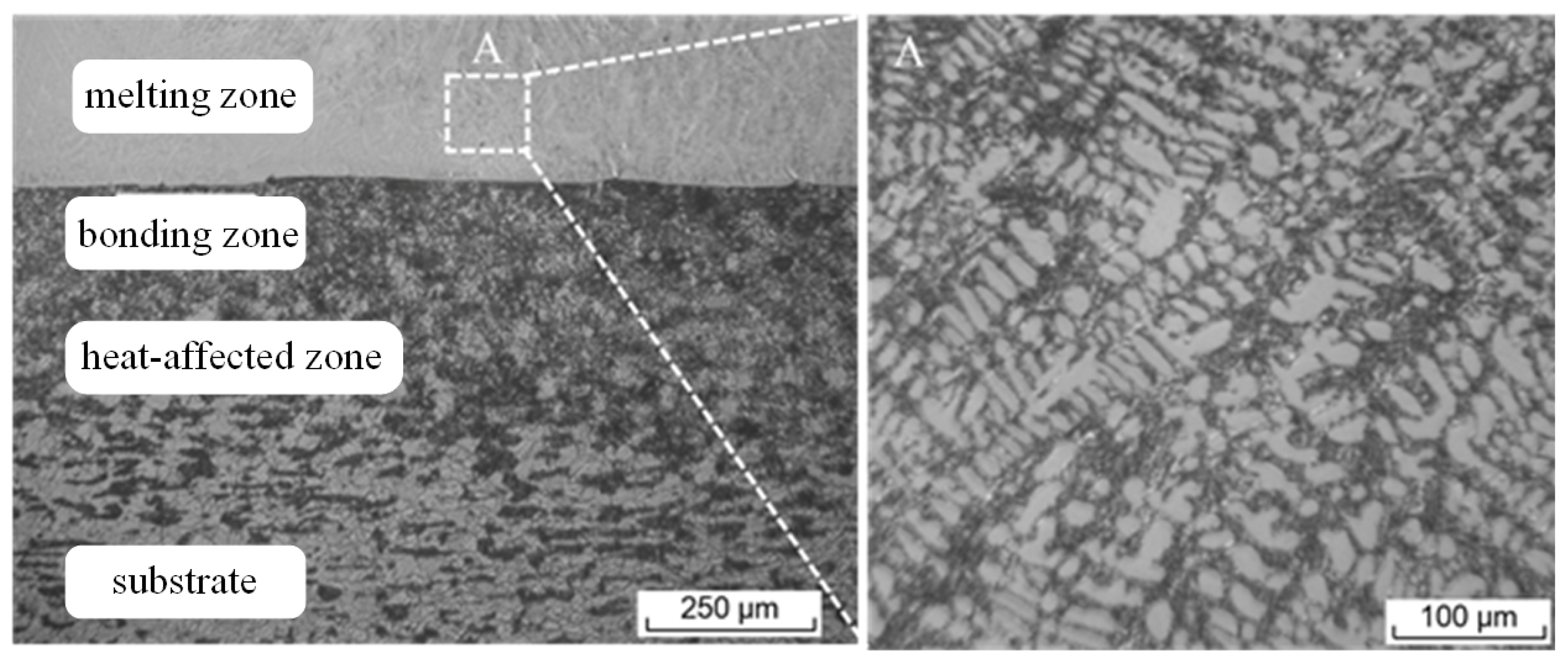
The cross-sectional morphology of the cladding layer is shown in Figure 1. It can be seen that the cladding layer and the matrix were metallurgically bonded, and the cladding layer consisted of a melting zone, bonding zone, and heat-affected zone. The structure in the melting zone was dense and uniform, without defects such as cracks or pores, and the crystal grains in the melting zone were fine dendrites. The morphology of the bonding zone was wavy, which was due to the instantaneous high temperature of the laser melting the substrate material to form a tiny molten pool [16]. In the heat-affected zone, the metallographic structure was denser closer to the junction zone. Meanwhile, when close to the junction zone, the grains of the substrate metallographic structure were refined and recrystallized under the instantaneous high temperature and rapid cooling of the laser shock [17,18].
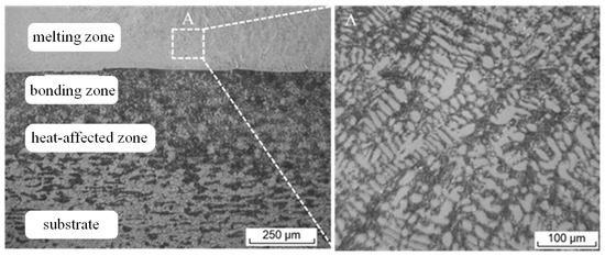
Figure 1.
The cross-sectional morphology of cladding layer: (A) partial enlargement of the cladding layer.
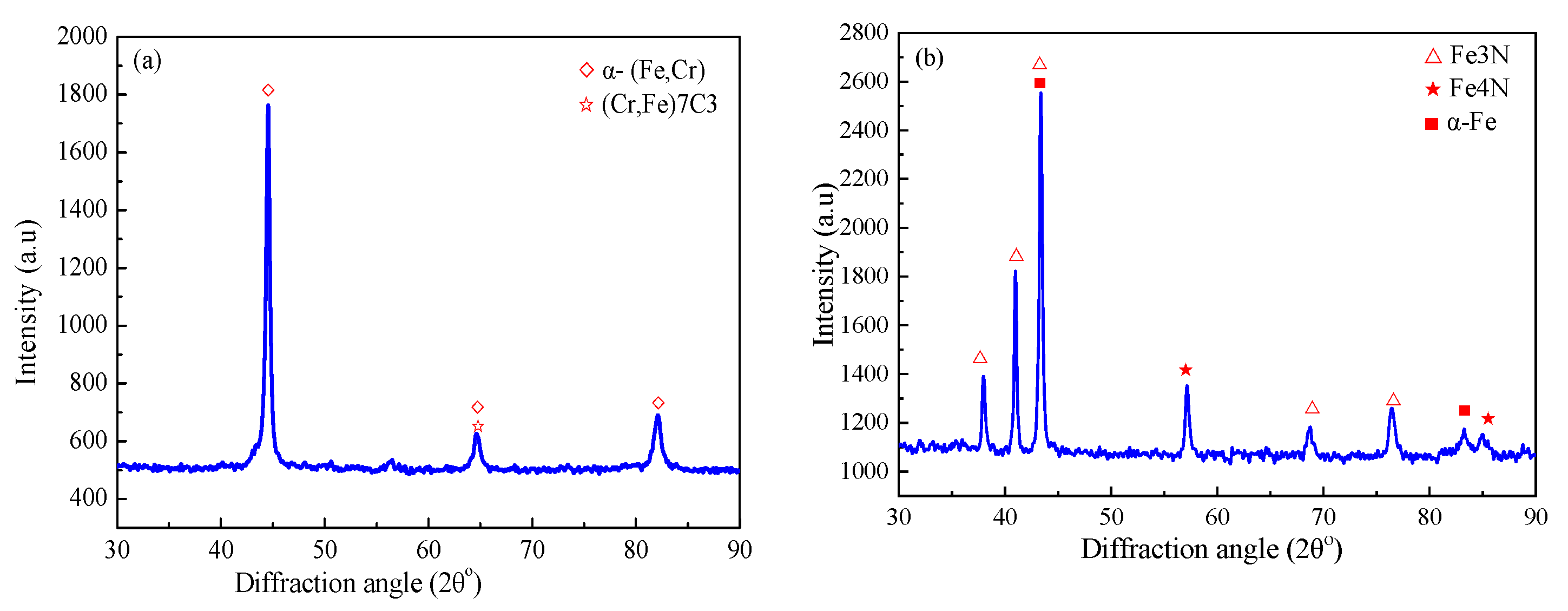
Figure 2 shows the XRD patterns of the cladding layer and nitriding layer. It reveals that compounds of α-(Fe, Cr) solid solution and (Cr, Fe)7C3 were generated in the cladding layer at the position of 2θ = 44.53°, 64.55°, and 82.09°. Similar results were obtained by Li et al. [17]. A Fe–Cr solid solution was formed due to the Cr atoms solute into Fe, thus simultaneously improving the strength and plastic toughness of the cladding layer. The elements of C and Cr in the iron-based powder were combined to form Cr7C3, which could improve the strength and hardness of the cladding layer [19].
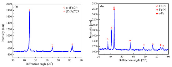
Figure 2.
XRD patterns of (a) cladding layer, and (b) nitriding layer.
For the nitriding layer, the main peak of the diffraction curve was Fe3N, and a dense compound layer was formed on the substrate. In the nitriding process, the nitrogen atom formed a nitrogen-containing solid solution. With the increase in nitrogen concentration, Fe3N and Fe4N were precipitated at a certain depth from the surface layer.
The cross-sectional micro-hardness of the cladding layer and nitriding layer is shown in Figure 3. For the cladding layer, the micro-hardness was obviously higher than that of the substrate. The gradient hardness decreased along the direction of the melting zone, transition zone, heat-affected zone, and substrate. The highest hardness of 694.0 HV0.5 was obtained in the melting zone, which was four times that of the substrate. For the nitriding layer, the gradient hardness distribution was similar to that of the laser cladding layer, and the highest hardness of the nitriding layer was 724.5 HV0.5, which was 4.2 times that of the substrate. Thus, it can be seen that: (i) the micro-hardness distribution on the laser cladding layer was more uniform, (ii) the thickness of the cladding layer was over 1.0 mm, and the that of the nitriding layer was 0.2 mm, and the thickness of the cladding layer was five times that of the nitriding layer.
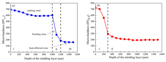
Figure 3.
The section micro-hardness of: (a) cladding layer and (b) nitriding layer.
The micro-hardness of the substrate was increased greatly after laser cladding and nitriding treatment, and the micro-hardness of the nitriding layer was higher than that of the laser cladding layer. The matrix contained a lot of cementite, and C atoms in the cementite entered the ferruginous compound during the nitriding process and caused lattice distortion of the ferruginous compound, thus improving the hardness of the nitride layer. However, many C atoms entered the compound layer, which impeded the infiltration of N atoms, thus the thickness of the nitride layer was very thin.
3.2. Tribological Performance
Figure 4a illustrates the friction coefficients of the substrate, cladding layer, and nitriding layer under dry sliding at 10 N for 3 h. The friction process of the substrate can be divided into the initial running-in stage and the stable stage. In the running-in stage, the friction coefficient rose rapidly to 0.72, and then declined sharply to 0.30 after sliding for 120 s, followed by gradually increasing to 0.34 at 490 s, and then reaching a stable stage. For the cladding layer, the friction coefficient quickly increased to 0.44, and then remained at 0.46. However, the friction coefficient of the nitriding layer increased rapidly to 0.47 in the initial stage, and then remained stable. The curve fluctuated sharply after sliding for 5300 s, and the highest value was 0.70. Throughout the experiment, the friction coefficient of the substrate was lower than that of the cladding layer and nitriding layer. The graphite in the substrate can generate a transfer film on the contact surface, which provided a self-lubricating effect and reduced the friction coefficient during the dry sliding [20]. Meanwhile, the friction coefficient of the cladding layer was obviously lower and more stable than that of the nitriding layer.
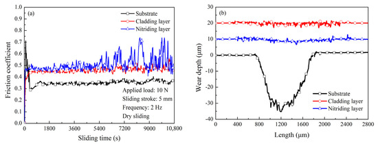
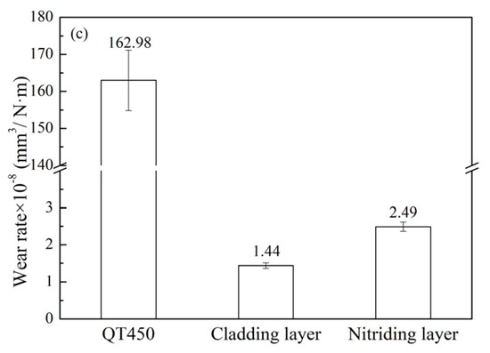
Figure 4.
(a) Friction coefficient, (b) wear depth, and (c) wear rates of substrate, cladding layer, and nitriding layer under dry sliding conditions.
When the steel ball slid against the lower sample, the asperity in the contact zone was embedded in each other under contact pressure. The layer with higher hardness had a stronger plastic deformation resistance and avoided severe adhesive friction. The hardness of the nitriding layer was lower than that of the cladding layer, thus the cladding layer showed a lower friction coefficient [21]. In addition, the gradient hardness of the nitriding layer was sharply decreased along the thickness direction (as shown in Figure 2b) and the adhesion was increased with the increase in the real contact area with the prolonged sliding time, which resulted in greater fluctuations in the friction coefficient [22].
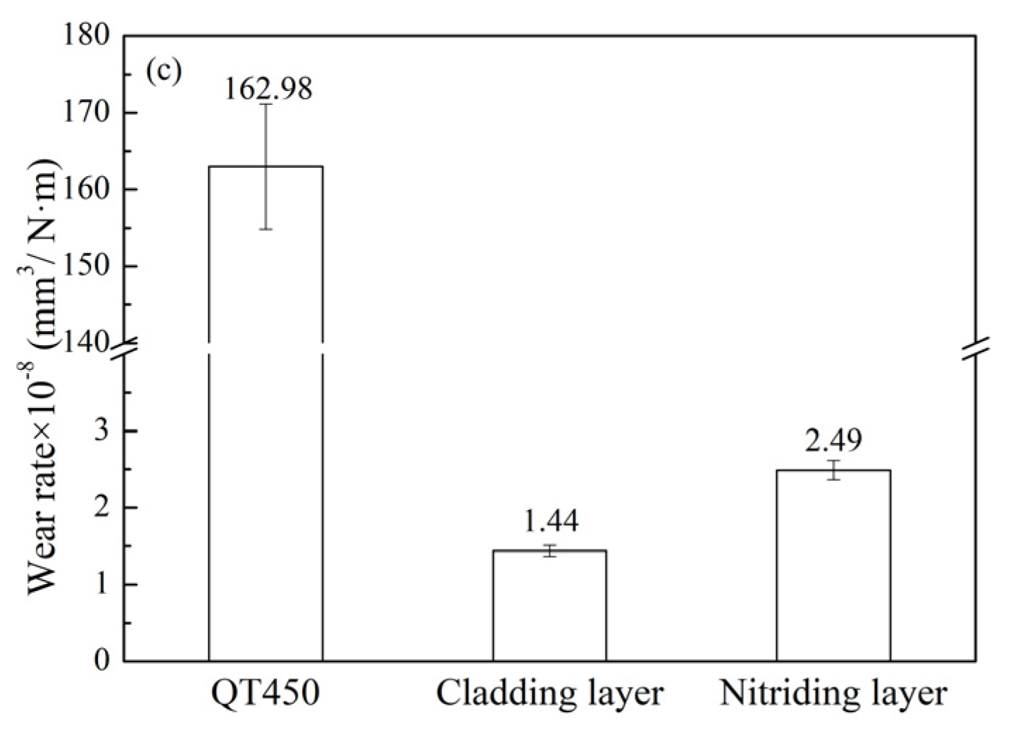
The wear profiles of the surfaces under dry sliding are shown Figure 4b. The width and depth of the wear track on nodular cast iron were 1200 and 35 μm. This demonstrates that the size of the wear track on the cladding layer and nitriding layer was obviously reduced. As shown in Figure 4c, the wear rates of the substrate, cladding layer, and nitriding layer were 162.98 × 10⁻⁶ mm3/Nm, 1.44 × 10⁻⁶ mm3/Nm, and 2.49 × 10⁻⁶ mm3/Nm, respectively, indicating that the wear resistance rates of the cladding layer and the nitriding layer were 113.2 and 65.5 times higher that of QT450. It is clear that the surface strengthening significantly improved the wear resistance of nodular cast iron under dry sliding conditions.
For the cladding layer, the Fe–Cr substitution solid solution as the strengthening phase effectively enhanced the hardness of nodular cast iron. For the nitriding layer, these nitrides (Fe3N, Fe4N) as the interstitial solid solution dispersed in the structure of nodular cast iron had higher micro-hardness and not only played a role in dispersion strengthening, but also produced a dislocation pinning effect, which further refined the surface grains of nodular cast iron, and effectively inhibited the plowing of the asperity on the steel ball, thereby improving the wear resistance [23]. However, the severe fluctuation of the friction coefficient of nitriding layer produced shock force, which induced more serious wear.
In this study, the friction and wear behaviors of three samples under starved lubrication conditions at applied loads of 100, 200, and 300 N were further studied.
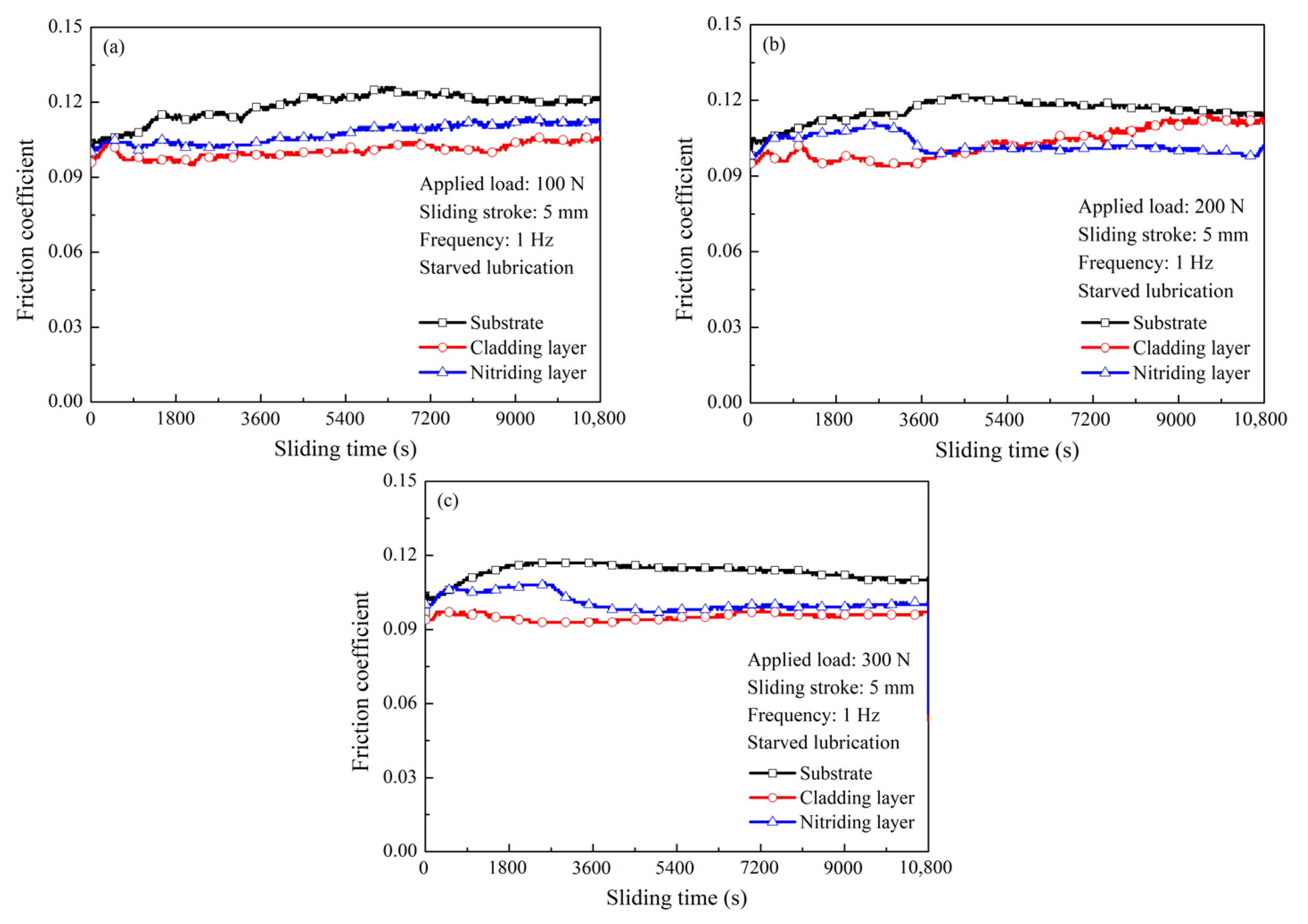
Figure 5 illustrates the friction coefficient of the samples at different applied loads. When the load was 100 N (Figure 5a), their friction coefficients were increased slowly with the increase in sliding time. Specifically, the friction coefficient of QT450 was 0.10 at the first stage, then increased to 0.125 after sliding for 6250 s, and its average friction coefficient was 0.118. In contrast, the average friction coefficient of the nitriding layer was 0.107, which was 9.3% lower than that of QT450. It is interesting that the friction coefficient of the cladding layer was the lowest and stable, and the average friction coefficient was 0.101. By increasing the load to 200 N (Figure 5b), the variation trends of their friction coefficient curves were obviously different. The friction coefficient of QT450 was gradually increased and then remained stable. The friction coefficient of the nitriding layer gradually increased first and then quickly declined to 0.10 and remained stable. Nevertheless, the friction coefficient of the cladding layer fluctuated significantly in the first 2800 s, and then gradually increased. Their average friction coefficients were 0.116, 0.102, and 0.103. When the applied load increased to 300 N (Figure 5c), the trends of the friction coefficient of the substrate and nitriding layer were similar to that of 200 N. An interesting phenomenon was that the friction coefficient of the cladding layer was the lowest and remained stable throughout the given test conditions.
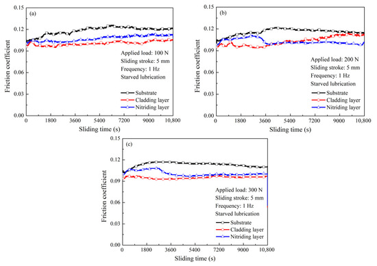
Figure 5.
Friction coefficients of three samples at loads of: (a) 100 N, (b) 200 N, and (c) 300 N under starved lubrication conditions.
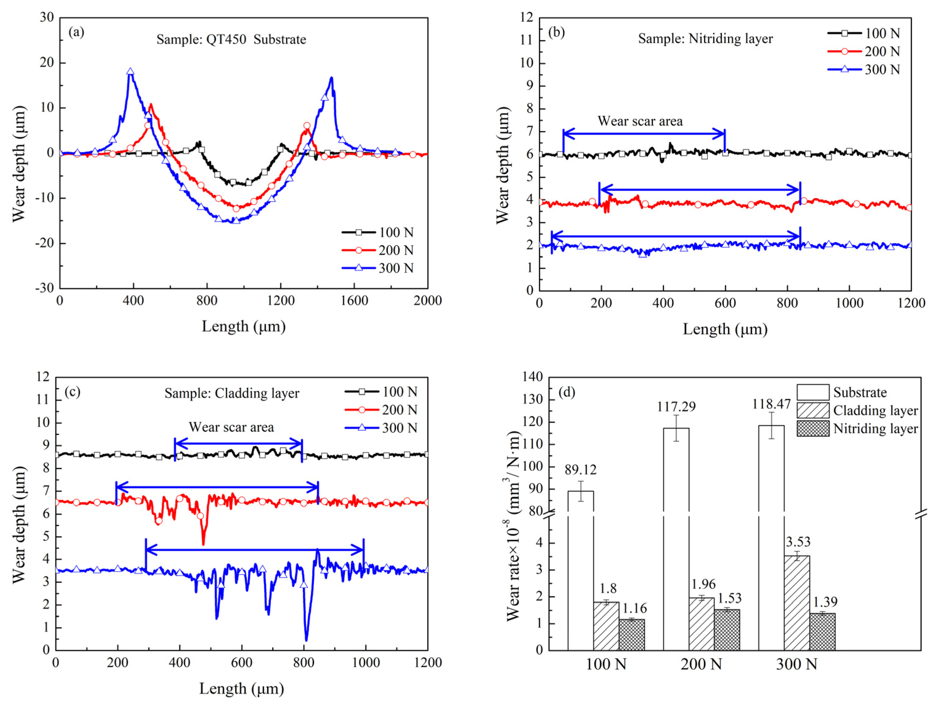
Figure 6 shows the cross-section profiles of the wear tracks under starved lubrication conditions. For QT450 (Figure 6a), a deep wear track and tiny bumps at the edge of the track were detected. The area of the wear track was increased with the increase in applied load, and the area of the wear track was 1925 μm2 under 100 N. When the load increased to 200 and 300 N, the areas of the wear track were 5067 and 7677 μm2, which were 2.6 and 4.0 times larger than that of 100 N. The wear track of the nitriding layer became shallower (Figure 6b), and the maximum width of the wear track was 635 μm at 200 N, and that further increased to 796 μm as the load increased to 300 N. For the cladding layer (Figure 6c), the wear track was relatively smooth and contained shallow grooves, and the width decreased by 19.4% compared with that of the nitriding layer under 100 N, but the depth had no obvious change. When the load increased to 300 N, the maximum width and depth of the worn track further decreased to 704 μm and 3.1 μm, respectively.
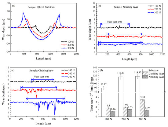
Figure 6.
The wear depth of: (a) substrate, (b) nitriding layer, (c) cladding layer, and (d) the wear rates at different loads.
The wear rates of the three samples were calculated and are summarized in Figure 6d. It can be seen that: (i) the wear rate of the substrate was the highest, followed by the cladding layer and nitriding layer. (ii) The wear rates of the substrate and cladding layer were evidently increased with the increase in normal load, while the wear rates of the nitriding layer were relatively stable, indicating that the wear resistance of the nitriding layer was superior to that of the cladding layer under starved lubrication.
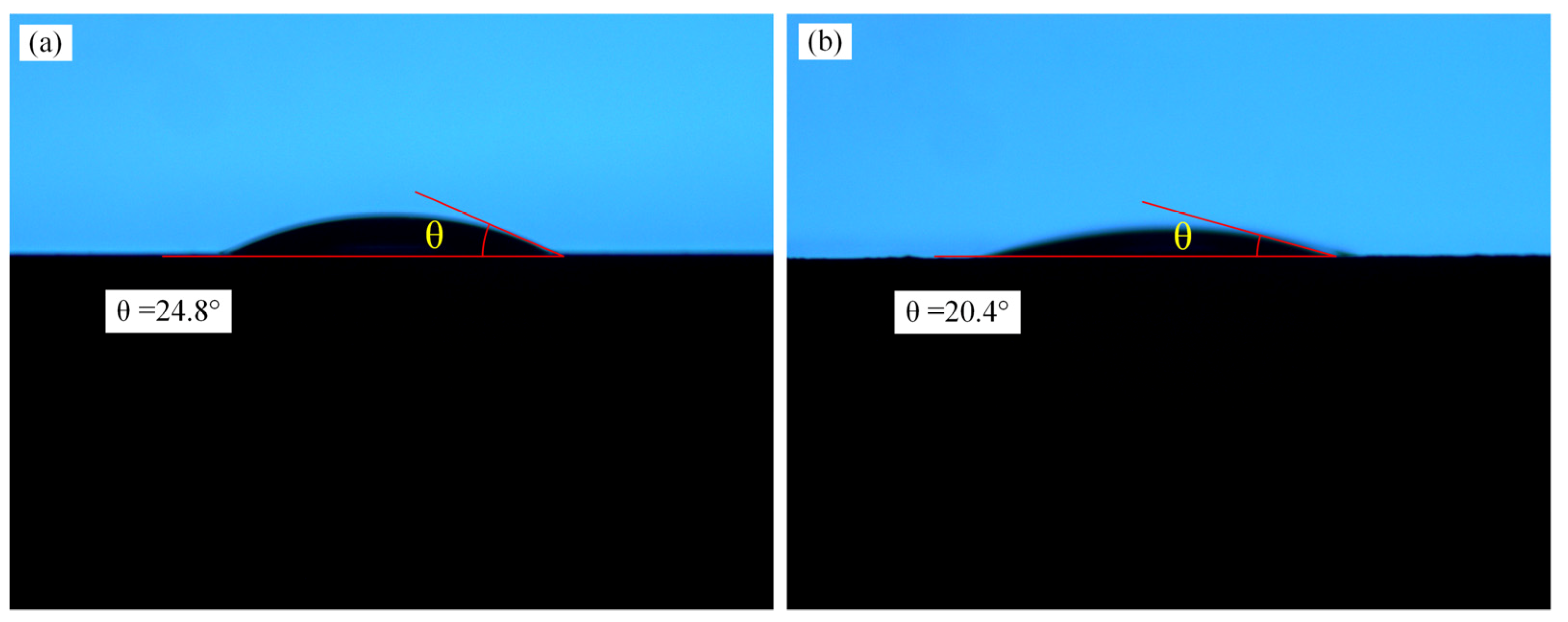
In order to further investigate the lubrication mechanism of the cladding layer and nitriding layer under starved lubrication conditions, the contact angle of the two layers was measured and is shown in Figure 7. The contact angles of the two layers were 24.8° and 20.4°, respectively. The lubrication property between friction pairs is mainly affected by the lubricant viscosity and surface wetting characteristics under oil lubrication conditions [24]. Many studies have also found that a lyophobic surface easily led to solid–liquid interface slip [25,26]. Solid–liquid interface slip can effectively reduce the velocity of the thin lubricant film near the bottom of the sample, thereby reducing the viscous force. This explains why the cladding layer demonstrated reduced friction compared to the nitriding layer. In the case of the same liquid surface tension and the same oil lubrication, a higher contact angle induces a lower oil film thickness [27]. Therefore, the oil film formed on the nitriding layer under starved lubrication was thicker, and the nitriding layer had the better wear resistance under starved lubrication conditions.
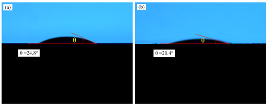
Figure 7.
Contact angles of (a) cladding layer and (b) nitriding layer.
3.3. Analysis of Worn Surface
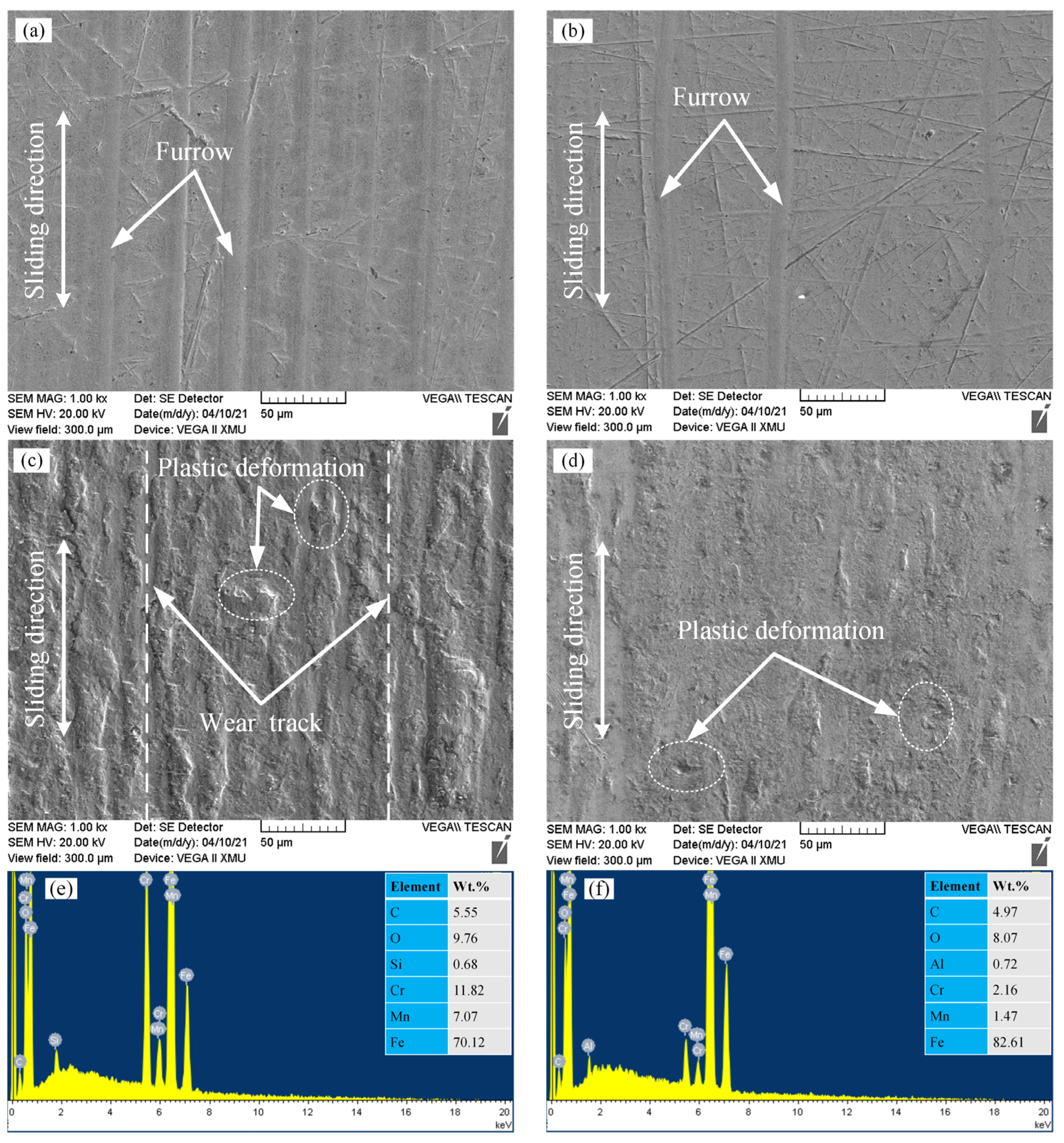
Figure 8a,b illustrate the wear track morphologies of the cladding layer and nitriding layer under starved lubrication at an applied load of 100 N. Obvious furrows were present on the surface of the cladding layer and nitriding layer, and original machining morphology still existed on the wear track, indicating that the two layers had slight wear. However, the number and size of furrows on the cladding layer were larger than those of the nitriding layer. It could be deduced that the boundary oil film on the cladding layer had poor strength and was liable to rupture during the sliding process.
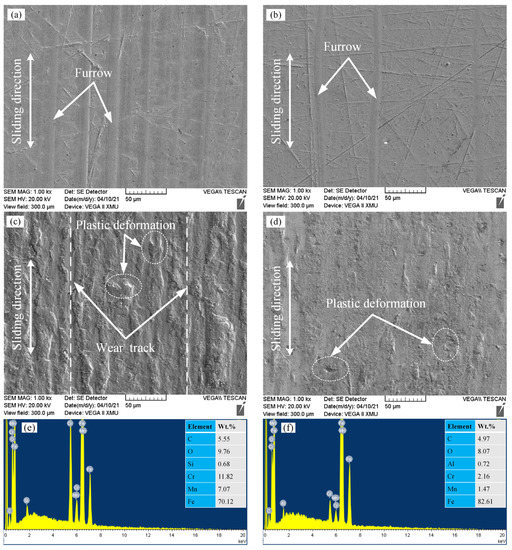
Figure 8.
SEM morphologies of the (a) cladding layer and (b) nitriding layer under starved lubrication of 100 N, (c) cladding layer and (d) nitriding layer under dry sliding of 10 N. EDS spectra of the (e) cladding layer and (f) nitriding layer under starved lubrication.
Figure 8c,d demonstrates the wear track on the cladding layer and nitriding layer after a dry friction test. In the case of cladding layer, the wear track presented parallel plows in the sliding direction and features of plastic deformation could also be clearly observed, indicating that adhesive wear was the main wear mechanism. It could be seen that the nitriding layer had a smoother wear track than that of the cladding layer under the same applied load.
Moreover, EDS analyses of wear tracks on the cladding layer and nitriding layer (marked in Figure 8c,d) are shown in Figure 8e,f. The elements of Cr and Mn were detected, which were from the steel ball. This suggests that the steel ball was easily peeled off and transferred to the layers under high sliding speeds and loads. The asperities on the steel ball were softened under contact stress and high frictional heat, and wear debris was easily produced and rolled and plowed into the contact area to cause obvious abrasive wear. The soft metal wear debris was rolled on the cladding layer during the friction process, which reduced the friction coefficient [28]. In addition, the content of Mn and Cr of the wear track on the nitriding layer was much lower than that of the cladding layer. This indicates that the amount of wear debris generated on the nitriding layer was not enough to form an effective rolling element, which resulted in a high friction coefficient with wide fluctuations (as shown in Figure 4a).
3.4. Contact Simulation Analysis
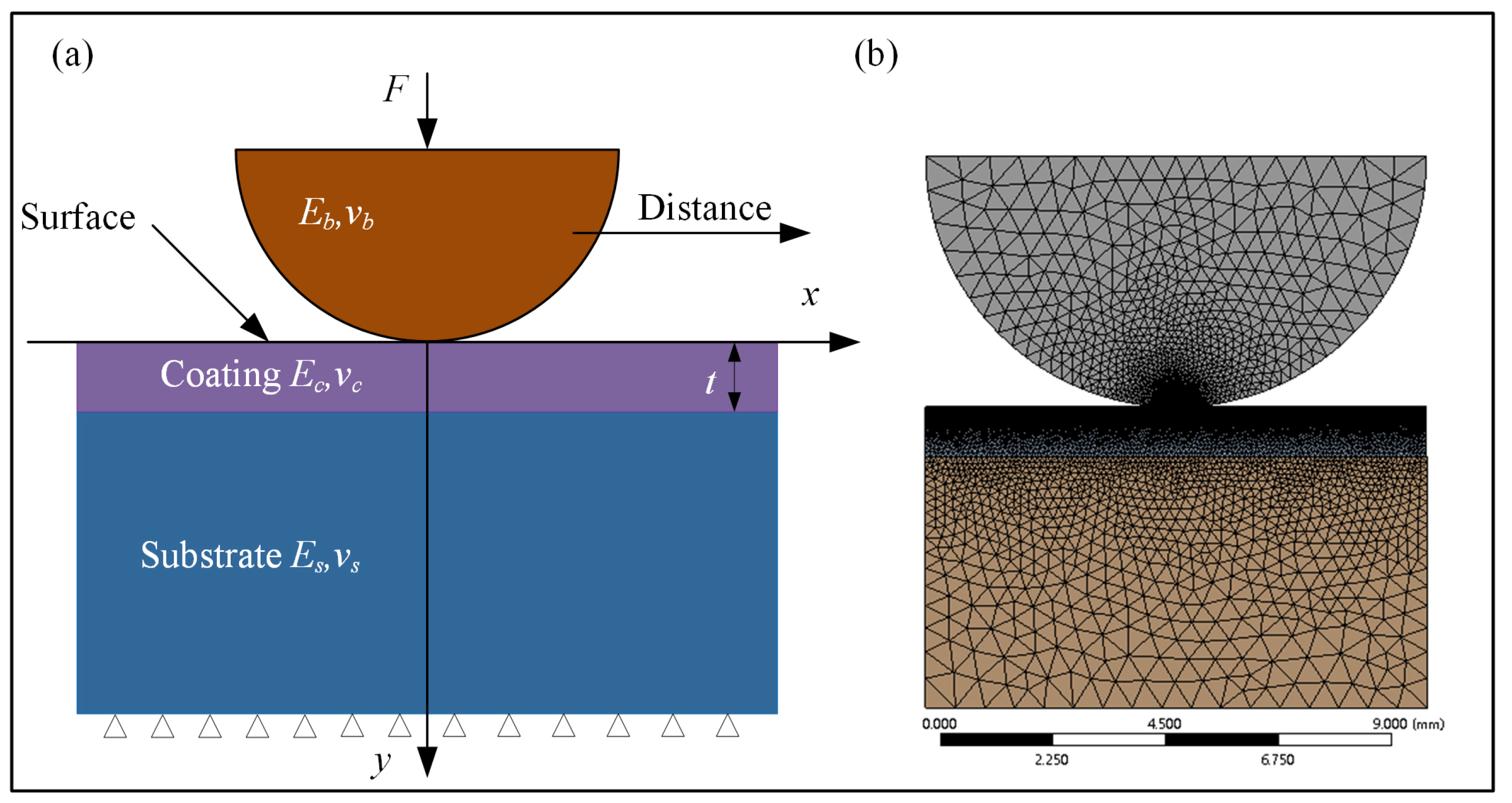
In order to further ascertain the wear resistance mechanism of the cladding layer and nitriding layer under dry sliding conditions, the finite element (FE) model, a two-dimensional plane strain ball-on-disk contact model (Figure 9a), was established using ANSYS (2020 R2). In this simulation, surface-to-surface contact elements conta172 were adopted, and the steel ball and the coating were selected as the contact surface and target surface, respectively. The physical properties of the materials are shown in Table 4. The friction contact model was selected, and the friction coefficient obtained from the dry tribological test was introduced into the simulation. The test process can be divided into the initial stage, middle stage, and later stage, and the average friction coefficients are shown in Table 5.
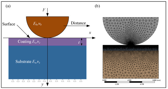
Figure 9.
Finite element model of the ball-on-disk contact: (a) geometric model; (b) meshing model.
Table 4.
Mechanical parameters of the materials.
Table 5.
Friction coefficient at different stages.
The triangle meshing method was adopted as a whole. According to the Hertz contact theory, the stress effect caused by contact was mainly distributed near the contact area. Therefore, the sphere of influence meshing method was used on the ball, and the gradually sparse meshing method was used on the disk to refine the mesh in the contact area [29], and the meshing model is shown in Figure 9b. The fixed constraint was set at the substrate bottom, all the degrees of freedom were constrained, a normal load of 10 N was applied on the steel ball, and, finally, the horizontal displacement of the steel ball was 1.0 mm.
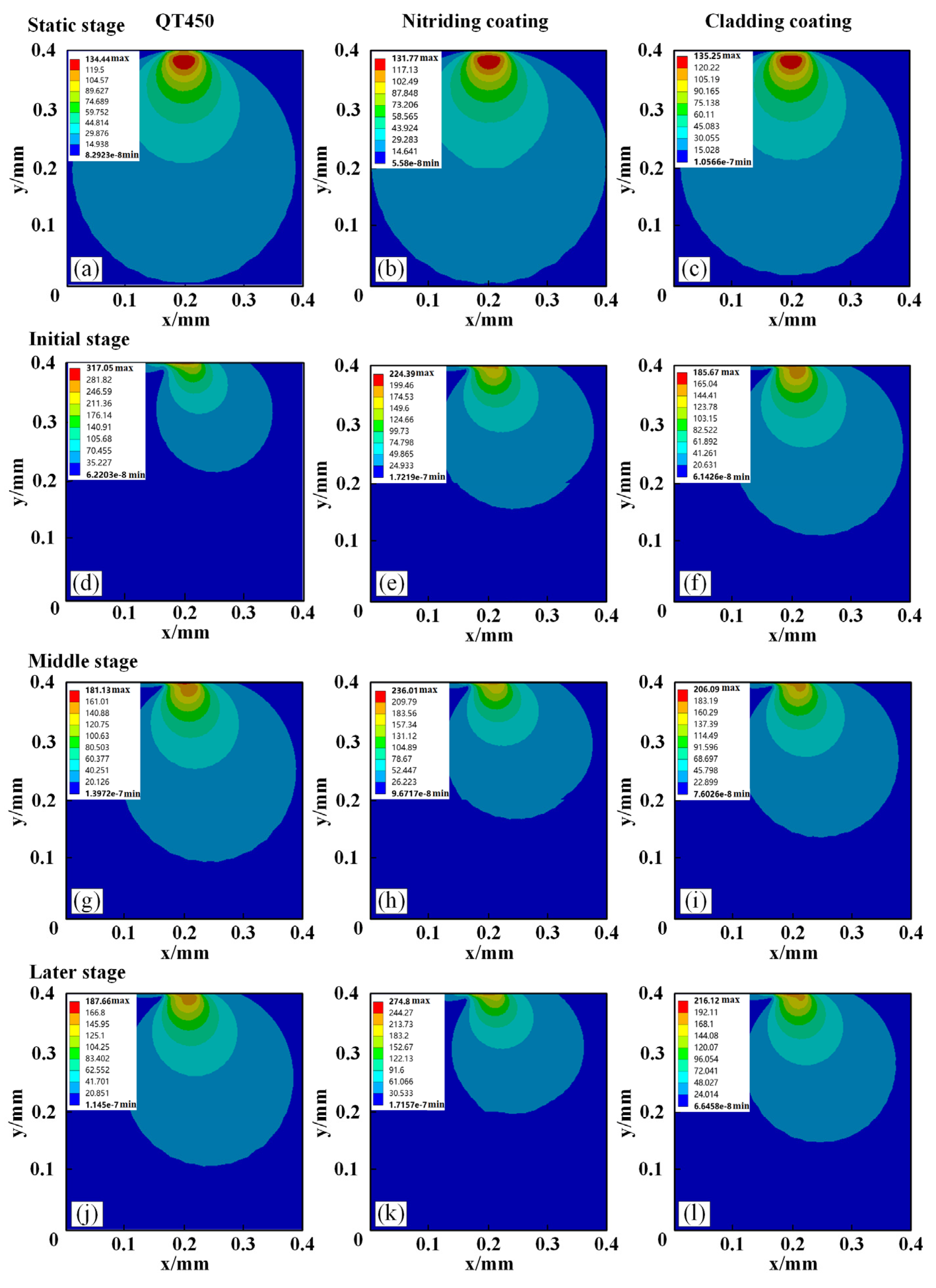
Figure 10 shows von Mises stress contours of the substrate and the two layers under static conditions (friction coefficient of 0) and dry sliding stages.
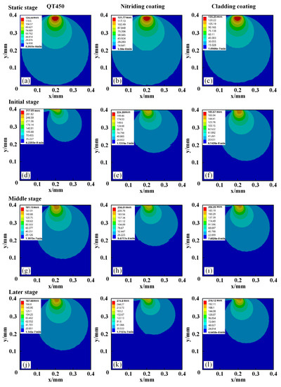
Figure 10.
Von Mises stress distribution of three samples at different friction coefficients: (a) static stage of substrate;(b) static stage of nitriding layer; (c) static stage of cladding layer; (d) initial stage of substrate (e) initial stage of nitriding layer;(f) initial stage of cladding layer;(g) middle stage of substrate;(h) middle stage of nitriding layer; (i) middle stage of laser cladding;(j) later stage of substrate;(k) later stage of nitriding layer;(l) later stage of cladding layer.
When in the static stage (as shown in Figure 10a–c), the von Mises stress contour lines spread out in an elliptical shape, and the peak von Mises stresses of the substrate, nitriding layer, and cladding layer were 134.4, 131.8, and 135.3 MPa, respectively. Their peak von Mises stresses were very close, but the area of von Mises stress in the nitriding layer was bigger than in the cladding layer.
When in the initial stage (as shown in Figure 10d,f), the distribution contours of the von Mises stress were no longer symmetric about the Y-axis and moved toward the sliding direction under kinetic friction. The von Mises stress contours biased to the front edge of the relative direction of the motion, and the von Mises stress of the trailing edge was smaller. It was also noted that the peak von Mises stress was increased with the increase in the friction coefficient.
When in the middle stage (as shown in Figure 10g,i), the peaks of von Mises stress on the nitriding layer and cladding layer were 274.8 and 216.1 MPa. Generally, the wear rate was directly proportional to the contact stress and inversely proportional to the surface hardness [30]. The peaks of von Mises stress on the nitriding layer were higher than those on cladding layer, indicating that the nitriding layer was more prone to yielding and falling off, which accelerated the wear.
4. Conclusions
In this study, the cladding layer and nitriding layer are fabricated on QT450 substrate, and their tribological performance under dry and starved lubrication conditions and the anti-wear mechanism are studied. The following conclusions are drawn:
- (1)
- When under dry sliding conditions, the wear rates of the cladding layer and nitriding layer are 1.44 × 10⁻⁶ mm3/Nm and 2.49 × 10⁻⁶ mm3/Nm, and the wear resistance values are 291.0 and 603.6 times that of QT450. The cladding layer significantly improves the wear resistance under dry sliding.
- (2)
- When under starved lubrication conditions, the friction coefficients of the cladding layer are 0.101, 0.103, and 0.097 under 100, 200, and 300 N, respectively, and it is the lowest and the most stable because of its higher contact angle. The wear rates of the cladding layer are 1.80 × 10⁻⁸ mm3/Nm, 1.96 × 10⁻⁸ mm3/Nm, and 3.53 × 10⁻⁸ mm3/Nm. The cladding layer still has excellent antifriction and wear resistance under the starved lubrication conditions.
- (3)
- The von Mises stress contours are symmetric with respect to the normal line of the contact point and diffuse outwards in an elliptical shape under the static contact conditions. However, the von Mises stress contours are inclined to the direction of relative motion as sliding started. The equivalent stress of the cladding layer is lower than that of the nitriding layer in the whole wear process, and the wear resistance of the cladding layer is excellent under dry sliding.
Author Contributions
Data curation, D.Z. and Z.L.; Funding acquisition, D.Z. and F.G.; Investigation, Z.L. and H.R.; writing—original draft preparation, Z.L.; writing—review and editing, D.Z., H.F., and F.G. All authors have read and agreed to the published version of the manuscript.
Funding
This work was support by the Chinese Postdoctoral Project (No. 2017M613171), Postdoctoral Foundation of Shaanxi Province (No. 2018BSHEDZZ09), and Shaanxi Key Laboratory of Mine Electromechanical Equipment Intelligent Monitoring (No. SKL-MEEIM201908), Shaanxi Province special technology innovation guidance (No. 2018ZKC-160).
Institutional Review Board Statement
Not applicable.
Informed Consent Statement
Not applicable.
Data Availability Statement
Not applicable.
Conflicts of Interest
The authors declare no conflict of interest.
References
- Li, Y.; Dong, S.; Yan, S.; Liu, X.; He, P.; Xu, B. Surface remanufacturing of ductile cast iron by laser cladding Ni-Cu alloy coatings. Surf. Coat. Technol. 2018, 347, 20–28. [Google Scholar] [CrossRef]
- Zammit, A.; Abela, S.; Betts, J.C.; Grech, M. Discrete laser spot hardening of austempered ductile iron. Surf. Coat. Technol. 2017, 331, 143–152. [Google Scholar] [CrossRef]
- Nguyen Van, T.; Nguyen, T.A.; Le Thu, Q.; Pham Thi, H. Influence of plasma spraying parameters on microstructure and corrosion resistance of Cr3C2-25NiCr cermet carbide coating. Anti-Corros. Methods Mater. 2019, 66, 336–342. [Google Scholar] [CrossRef]
- Mousavi, R.; Bahrololoom, M.E.; Deflorian, F. The effect of surfactant on the microstructure and corrosion resistance of electrodeposited Ni-Mo alloy coatings. Anti-Corros. Methods Mater. 2019, 66, 631–637. [Google Scholar] [CrossRef]
- Lee, H.K.; Park, S.H.; Kang, C.Y. Effect of plasma current on surface defects of plasma-MIG welding in cryogenic aluminum alloys. J. Mater. Process. Technol. 2015, 223, 203–215. [Google Scholar] [CrossRef]
- Torims, T.; Pikurs, G.; Ratkus, A.; Logins, A.; Vilcans, J.; Sklariks, S. Development of technological equipment to laboratory test in-situ laser cladding for marine engine crankshaft renovation. Procedia Eng. 2015, 100, 559–568. [Google Scholar] [CrossRef] [Green Version]
- Emamian, A.; Corbin, S.F.; Khajepour, A. Tribology characteristics of in-situ laser deposition of Fe–TiC. Surf. Coat. Technol. 2012, 206, 4495–4501. [Google Scholar] [CrossRef]
- Wang, W.; Liu, Y.X.; Xing, F.; Xie, H.L. Laser remanufacturing technology and its applications. Adv. Mater. Res. 2010, 139, 1424–1427. [Google Scholar] [CrossRef]
- Zhao, N.; Tao, L.; Guo, H.; Zhang, M.Q. Laser clad NiCrBSi alloy wear-resistance coating with RE addition on heavy duty spur gear flank. IOP Conf.Ser. Mater. Sci. Eng. 2017, 248, 012016. [Google Scholar] [CrossRef]
- Guo, H.M.; Wang, Q.; Wang, W.J.; Guo, J.; Liu, Q.Y.; Zhu, M.H. Investigation on wear and damage performance of laser cladding Co-based alloy on single wheel or rail material. Wear 2015, 328, 329–337. [Google Scholar] [CrossRef]
- Weng, Z.; Wang, A.; Wang, Y.; Xiong, D.; Tang, H. Diode laser cladding of Fe-based alloy on ductile cast iron and related interfacial behavior. Surf. Coat. Technol. 2016, 286, 64–71. [Google Scholar] [CrossRef]
- Janicki, D. The friction and wear behaviour of in-situ titanium carbide reinforced composite layers manufactured on ductile cast iron by laser surface alloying. Surf. Coat. Technol. 2021, 406, 126634. [Google Scholar] [CrossRef]
- Li, Y.; Dong, S.; He, P.; Yan, S.; Li, E.; Liu, X.; Xu, B. Microstructure characteristics and mechanical properties of new-type FeNiCr laser cladding alloy coating on nodular cast iron. J. Mater. Pro. Technol. 2019, 269, 163–171. [Google Scholar] [CrossRef]
- Yilmaz, K.B.; Comez, I.; Yildirim, B.; Güler, M.A.; El-Borgi, S. Frictional receding contact problem for a graded bilayer system indented by a rigid punch. Int. J. Mecha. Sci. 2018, 141, 127–142. [Google Scholar] [CrossRef]
- Balci, M.N.; Dag, S. Solution of the dynamic frictional contact problem between a functionally graded coating and a moving cylindrical punch. Int. J. Solid. Sci. 2019, 161, 267–281. [Google Scholar] [CrossRef]
- Wang, S.L.; Zhang, Z.Y.; Gong, Y.B.; Nie, G.M. Microstructures and corrosion resistance of Fe-based amorphous/nanocrystalline coating fabricated by laser cladding. J. Alloy. Compd. 2017, 728, 1116–1123. [Google Scholar] [CrossRef]
- Li, Y.; Dong, S.; Yan, S.; Liu, X.; He, P.; Xu, B. Microstructure evolution during laser cladding Fe–Cr alloy coatings on ductile cast iron. Opt. Laser Technol. 2018, 108, 255–264. [Google Scholar] [CrossRef]
- Zhang, F.; Qiu, Y.; Hu, T.; Clare, A.T.; Li, Y.; Zhang, L.C. Microstructures and mechanical behavior of beta-type Ti-25V-15Cr-0.2Si titanium alloy coating by laser cladding. Mater. Sci. Eng. A 2020, 796, 140063. [Google Scholar] [CrossRef]
- Yang, Y. Microstructure and properties of laser-clad high-temperature wear-resistant alloys. Appl. Surf. Sci. 1999, 140, 19–23. [Google Scholar] [CrossRef]
- Zhang, D.; Li, Z.; Wang, L.; Kong, L.; Gao, F.; Wang, Q. Study on tribological properties of boronized and textured composite surface and its application on camshaft connecting-rod type hydraulic motor. Wear 2021, 482–483, 203964. [Google Scholar] [CrossRef]
- Cui, G.; Han, B.; Zhao, J.; Li, M. Comparative study on tribological properties of the sulfurizing layers on Fe, Ni and Co based laser cladding coatings. Tribol. Int. 2019, 134, 36–49. [Google Scholar] [CrossRef]
- Pereira, J.; Zambrano, J.; Licausi, M.; Tobar, M.; Amigó, V. Tribology and high temperature friction wear behavior of MCrAlY laser cladding coatings on stainless steel. Wear 2015, 330-331, 280–287. [Google Scholar] [CrossRef]
- Hu, D.; Liu, Y.; Chen, H.; Wang, M. Microstructure and wear resistance of Ni-based tungsten carbide coating by laser cladding on tunnel boring machine cutter ring. Surf. Coat. Technol. 2020, 404, 126432. [Google Scholar] [CrossRef]
- Hao, X.; Sun, P.; Xiao, S.; Yang, Y.; Li, L. Tribological performance of surface with different wettability under ball-on-disc test. Appl. Surf. Sci. 2020, 501, 144228. [Google Scholar] [CrossRef]
- Stevens, M.J.; Mondello, M.; Grest, G.S.; Cui, S.T.; Cochran, H.D.; Cummings, P.T. Comparison of shear flow of hexadecane in a confined geometry and in bulk. J. Chem. Phys. 1997, 106, 7303–7314. [Google Scholar] [CrossRef] [Green Version]
- Sun, M.; Ebner, C. Molecular dynamics study of flow at a fluid-wall interface. Phys. Rev. Lett. 1992, 24, 3491–3494. [Google Scholar] [CrossRef] [PubMed]
- Wei, J.; Shu-yi, L.; Zhao-gang, J. Effect of wettability of solid/liquid interface on film lubrication in line contact. Surf. Technol. 2020, 49, 252–257. [Google Scholar]
- Ma, H.; Liang, G.; Lv, M.; Huang, Y.; Han, Y. Investigation on friction and wear behavior of aisi 4340 steel in dry sliding condition. Tribology 2017, 38, 59–66. [Google Scholar]
- Arslan, O. Hertz-type frictional contact problem of a bidirectionally graded half-plane indented by a sliding rounded punch. Mech. Mater. 2020, 149, 103539. [Google Scholar] [CrossRef]
- Kraghelsky, I. Calculation of wear rate. J. Bas. Eng. 1965, 87, 785. [Google Scholar] [CrossRef]


Publisher’s Note: MDPI stays neutral with regard to jurisdictional claims in published maps and institutional affiliations. |
© 2021 by the authors. Licensee MDPI, Basel, Switzerland. This article is an open access article distributed under the terms and conditions of the Creative Commons Attribution (CC BY) license (https://creativecommons.org/licenses/by/4.0/).