Article

Production and Characterization of Al-Si Coatings Fabricated by Mechanical Alloying Method on Inconel 625 Superalloy Substrates

by
Serhan Köktaş
*,
Ali Bülent Önay
and
Ahmet Çağrı Kılınç
Department of Metallurgical and Materials Engineering, Faculty of Engineering, Dokuz Eylul University, Izmir 35390, Turkey
*
Author to whom correspondence should be addressed.
Coatings 2021, 11(9), 1016; https://doi.org/10.3390/coatings11091016
Submission received: 5 July 2021 / Revised: 13 August 2021 / Accepted: 20 August 2021 / Published: 25 August 2021
(This article belongs to the Special Issue Advances in Nanostructured Thin Films and Coatings)

Abstract

:
Inconel superalloys are used substantially in high-temperature environments. However, these alloys suffer from corrosion and wear. Attempts to overcome these drawbacks involve coating the metal with different techniques and materials. In this study, a new method with increasing potential was utilized. Using the mechanical alloying process in a planetary ball mill vial, alloying and the Al-Si coatings were concurrently achieved on Inconel 625 substrates. Different process control agent (PCA) ratios, milling ball diameters, and milling times were used to improve coating properties. Macro and microstructure, morphology, microhardness, and roughness values of samples were evaluated and compared. Additionally, crystallographic and cross-sectional properties were investigated in order to optimize the processing conditions. The results indicated that increasing the diameter of the grinding ball enhanced the hardness and thickness of these coatings and increased the roughness values. Longer processing time also enhanced the thickness with mechanical values. However, under these conditions, coating homogeneity decreased, and incompatible regions were formed on the coatings. PCA content brought a refined grain structure, hence showed better mechanical properties. On the other hand, processing time should be increased to get a denser and thicker protective layer against the operational conditions.

Graphical Abstract

1. Introduction

Due to their excellent high-temperature creep and mechanical properties, superalloys are widely used in aerospace, especially in gas turbine engines and energy production systems exposed to extremely high temperatures. However, exposure to long-term oxidant and corrosive environments calls attention to another important property of these materials, surface oxidation [1]. The corrosion properties of these materials could be improved by adding sufficient amounts of alloying elements like chromium, aluminum, or silicon to form Cr2O3, Al2O3, and SiO2 on the surface, respectively [2]. The best way to achieve a protective surface is by applying a coating of protective layer(s). High-temperature coatings, i.e., diffusion [3,4], overlay [5], and thermal barrier coatings (TBC) [6], are mainly preferred for providing these materials with advanced protection for decades.
High-temperature coatings produced on nickel-based superalloys can be classified into three different material combinations. These are aluminides (M-Al), modified (with precious metals) aluminides (M, Pt)Al or (M, Pd)Al [7], and MCrAlX alloys (Ni, Co or Fe as M), and (Y, Zr or Si as X). Additionally, there are TBC systems containing a ceramic top layer, e.g., ZrO2, together with the coatings mentioned above [8,9]. Moreover, Al-Si coatings produced on these high-temperature alloys were reported to improve the high-temperature oxidation resistance of these alloys [10,11].
Silicon addition was found as an effective way to improve the oxidation resistance of aluminide coatings. Low oxygen pressure fusing [10], powder pack cementation [12], hot dipping [13], slurry method [14], and hot stamping [15] methods were studied to form Al-Si coatings on different substrate materials to improve oxidation resistance. The formation of an additional oxide phase (SiO2) further benefits the protection of the nickel-based superalloy substrate, by delaying the formation of harmful phases (NiO and γ′-Ni3Al) [16]. In addition, Fu et al. (2014) reported that both coating elements react with nickel and form Ni2Si and Ni3Al, and the addition of Si promotes the formation of higher Al content NiAl phase (which is favorable to form protective Al2O3) from Ni3Al [11]. Zang et al. also reported that adding silicon helps to form a dense Al2O3 layer, and sets a barrier to oxygen diffusion [13]. Mechanical alloying (MA), also known as mechanical milling, is a solid-state powder mixing and powdered alloy production [17] technique. This technique produces homogeneous equilibrium or non-equilibrium alloy phases using mixtures of different powders, including at least one ductile metal, in an appropriate ball milling device. The particles collide with each other with the help of milling balls. The impact and sliding friction energy make the powders cold weld with severe deformation. After this severe deformation, particles fracture, and fine, in situ alloyed structures are obtained [18,19,20]. As a coating process, MA has recently become an alternative and attractive operation for producing in situ obtained alloy layers directly by using a powder mixture on bulk substrates to improve properties like mechanical, wear, oxidation, thermal shock, and thermal conductivity [21,22,23,24,25,26,27,28].
MA is very dependent on many process parameters as well as the properties of the powders used in the blend [29]. So far, only parameters like substrate hardness and the type of process device have been examined [30,31] for coatings produced by mechanical alloying. In this present study, the effect of grinding ball size, process control agent (PCA) content, and milling time were investigated as coating process parameters. These are some of the first parameters that come to mind when mechanical alloying is the subject [32,33]. In addition, an Al-Si powder mixture was used to produce a dense, homogeneous, strongly adhering, and potentially protective intermetallic alloy coating on Inconel 625 superalloy surface by using a planetary ball mill.

2. Materials and Methods

2.1. Materials

Inconel 625 superalloy discs with 2.5 mm thickness were cut from a rod with 12 mm diameter and were used as a substrate material for coating studies. Stearic acid (SA) was used as the process control agent (PCA), to obtain the balance between cold welding and fracturing of the particles while mechanical alloying, and enhance the process efficiency [33]. High purity Al powder (Sigma, St. Louis, MO, USA: 7429-90-5) with 60 µm max. particle size and Si powder (Sigma: 7440-21-3) with 45 µm max. powder size were used as mechanical alloying input, with a weight ratio of 85/15 respectively to maintain a hypereutectic alloy structure (see Table 1).

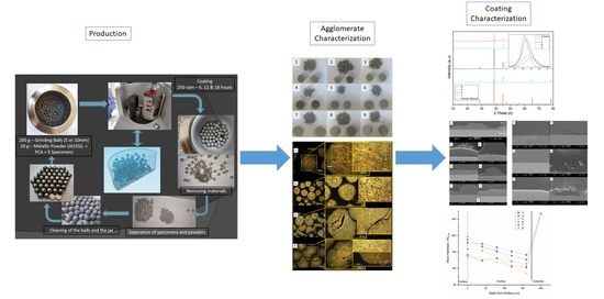
2.2. In Situ Mechanical Alloying and Coating Production

For mechanical milling operations, a planetary ball mill device (Retsch PM 100, Hahn, Germany) with a standard 500 mL hardened steel grinding jar and 200 g of grinding balls (Retsch, Hahn, Germany; 58 to 63 HRC hardness) were used. Grinding balls with different diameters (5 and 10) were selected in order to understand the effects of ball size on the homogeneity of the coating layer. Powder to ball ratio was specified as 1/10 (20 g of metal powder), different PCA ratios, and milling times were selected to examine the effect of these parameters (Table 2). The milling processes were performed in ambient conditions with a milling speed of 250 rpm. In order to avoid the rise in temperature during the coating process, 5 min of coating application was followed by 5 min of cooling of the vial (see Figure 1).
Following each coating process, in order to prevent contamination, the grinding vial and balls were cleaned by using sodium hydroxide solution for aluminum cleaning. Aluminum reacts with sodium hydroxide to produce aluminum hydroxide and becomes easily removable from the system. For further cleaning, quartz sand was used in the vial with grinding balls, and milling was applied for 20 min. Finally, methanol was used to get a perfectly cleaned surface on the vial and balls.

2.3. Characterization

After production of the coatings, remaining mechanically alloyed powders were examined to understand their alloying performance. The particles were prepared using a standard specimen preparation procedure by mounting in two-component epoxy resin, grinding from 80 to 1200 grit sandpaper, and polishing with 3 µm diamond paste. Their dimensional, microstructural, and mechanical properties were identified using a stereomicroscope (ZEISS SteREO Discovery, AG, Jena, Germany), an optical microscope (Nikon Eclipse ME 600, Tokyo, Japan), and a micro-hardness tester (Shimadzu HMV-2, Tokyo, Japan).
Cross-sections of coatings were prepared with the same specimen preparation route. To protect the coating from any harm, grinding was applied parallel to the interface. The specimens were investigated using SEM (JEOL JSM 6060, Tokyo, Japan) and EDS to observe the substrate-coating interface, adhesion, and homogeneity of the alloyed coating. The overall hardness values of coatings were measured by using a 1-kg load (HV1). Average coating thicknesses were calculated randomly from all over the cross-section profiles of coatings (both from narrower and thicker parts), and the average of the 20 measurements by using an optical microscope. Cross-sectional hardness profiles were prepared by using five hardness values, and these values were obtained by using a microhardness tester (Shimadzu HMV-2) with 50 g load (HV0.05). Following the application of background fitting, the average surface roughness of coatings (Ra) was determined using a surface profilometer (Ambios Technology XP-2, Santa Cruz, CA, USA). Furthermore, crystalline phase structures of the coatings and powder mixture were determined by using Rigaku Ultima 3 device (Rigaku, Tokyo, Japan) with Cu—Kα radiation (λ-Kα1 = 1.54 Å), the device was set to 40 kV and 30 mA power, and scanning was done between 10° and 80° range with 2°/min scan rate and 0.02°/step. Crystallite sizes were calculated by using Sherrer’s equation [34].
d = k × λ β × cos θ
where d is the crystallite size, λ is the X-ray wavelength, β is the width of the peak (full width at half maximum (FWHM)), θ is the Bragg angle, and K is the Scherrer constant (K was taken as 0.94).

3. Results and Discussion

3.1. Macroscopic Examination

The coatings and powder produced on Inconel 625 surfaces by mechanical alloying were first examined macroscopically. Optical and stereographic images of the specimens can be seen in Figure 1 and Figure 2, respectively. The grain sizes for each coating are large because of the amount of PCA used in the process. In order to enable powders to agglomerate and create a dense layer on the surface, PCA amount in the process was kept low in PCA-containing mixtures. For each coating parameter, the surfaces of samples show a continuous layer on the substrates. Because as-produced alloys have large grain sizes, the surfaces of coatings result in high roughness values as well. This macroscopical examination also shows that the resultant particles are larger and the surface structures are rougher for the materials processed with 10-mm grinding balls (the first, second, and third samples) than those processed with 5-mm grinding balls.
Stereographic examination of the specimens shows further evidence of the surface structure of the coatings. Uniform coating consolidation was achieved by producing a dense layer on the substrate and having ductile particles performing plastic deformation. With the addition of PCA (left to right in Figure 3a), the surface grain structure becomes smaller. However, this addition also changes the geometrical shape of these surfaces. The irregular shape of particles makes the surface hard to cover. The coating process will fail if there are gaps, cracks, or other interfacial voids [35]. Moreover, one-dimensional powders (spheres) will be more controllable and will have higher accuracy in transforming the particles into the cold-welded coating [36]. Additionally, with the increasing PCA content, the surface morphology of coatings shows some crack-like separation on particle junctures (Figure 3b—coating 6).

3.2. Characterization of Alloy Particles

As the powder mixture starts to form an alloy, it either produces an agglomerate or forms a coating layer on substrates. Thus, the resultant particles and surface layer produced during the alloying and coating processes are very similar in their structure. Produced particles were examined on an optical microscope to clearly understand the formation process of the coating (Figure 4). The lamellar structure of the ductile Al constituent surrounds the brittle Si particles.
The process transformed the powder mixture into an alloy, and microstructures of particles showed a typical hypereutectic alloy structure [37,38]. At the same time, plastic flow marks arose on the produced alloy particles and can be seen in higher (500×) magnifications. Particles produced with 10-mm grinding balls are coarser than those with 5-mm balls. Naturally, the particles form alloys faster because of the higher energy input obtained from larger ball sizes; however, the resulting particles show some porosities (Figure 4—no 1). Coarser particles mean coarser coatings, hence rougher surfaces when coated, which is discussed in Section 3.3. While the alloy formation process continues, plastic deformation occurs on ductile aluminum powders, forming the matrix phase. Brittle silicon powders fracture and decrease in size with increasing time. During MA, Suryanarayana indicated that [18], brittle constituents are encapsulated by ductile constituents. The brittle particle is closely spaced between the interlamellar spacings of elongated ductile structure. With the continuation of the alloying process, the ductile particles undergo work hardening and the lamellar structure is intertwined and the grain structure refines. With increasing MA time, the alloy powder particles get work hardened, the hardness and consequently the brittleness increases [18]. On the other hand, PCA content hinders ductile particles from agglomerating and acts as a surfactant to fracture particles by penetrating into microcracks during the alloying process [39]. However, in order to produce a homogeneous coating on a substrate, particles should cold-weld and remain agglomerated. The sixth sample with 0.5% PCA content shows a very fine grain structure, which is desired. However, this structure also contains very large cracks inside, which could cause problems as a coating.
In Figure 5, hardness values for different parameters are given. Smaller grain structures show advanced mechanical properties with increasing plastic deformation. However, Figure 4 shows that the increase in the deformation with increasing time causes incompatible structures between the center and edges of particles on the ninth sample. The center of alloy particles was formed in the earlier stages of the mechanical milling process. With time, the edges of particles deform further and become harder via deformation hardening. This problem results in cracks and voids in the particles after a processing time longer than 6 h.

3.3. Coating Characterization

Chemical composition obtained from EDS analysis of mechanically alloyed coating is shown in Figure 6. EDS no 1 shows the general coating composition and contains ≈ 17% silicon content. The silicon amount is a little higher than the powder mixture ratio (15% silicon), just probably because the EDS results could not precisely give the exact amounts. The different phase structures on the image can be identified as the darker matrix phase of α-Al matrix containing 10.6% of silicon (approximately eutectic composition, second EDS) and the lighter silicon particles (third EDS). As a result of the MA process, it was concluded that the desired alloy was formed.
Figure 7 shows the XRD phase development of produced alloy coatings with the starting powder mixture. Because of their nature, Al-Si hypereutectic alloys do not form an intermetallic compound after forming an alloy via mechanical alloying; α-Al solid solution and Si diffraction peaks remain separate. Still, peak heights and widths changed after MA was applied via increasing silicon content in the α-Al matrix. Moreover, increasing time and PCA amount, decreased the crystallinity of MA-alloyed coatings.
While the initial powder mixture has very intense and narrow aluminum and silicon phase diffractions, the coatings clearly show wider and lower intensity peaks, which is reasonable with mechanical alloying. This change is due to the increase of the amorphousness of the structure [18,40]. Because the number of dislocations, grain boundaries, and other faults increases by cold working, the imperfections of crystals increase. Therefore, it could be concluded that the amorphousness (the amount of disorder) increases too. Furthermore, because the increase in the milling time results in higher deformation, d-spacings (interplanar distances) of lattice planes shift to the right with an increase in 2θ degrees (Table 3), which could be explained by the increase of the residual stress. Likewise, the relation between the fourth and sixth samples shows that increasing stearic acid content also decreases the crystallinity of the structure. It was observed that the calculated crystallite sizes decreased with the increasing of ball size and PCA. However, no change was observed in the crystallite dimensions depending on the increase in time.
Cross-section SEM examinations (Figure 8 and Figure 9) give some brief information about the homogeneity and surface morphology of coating thicknesses. Figure 8a represents the low magnification (33×) coating profile of the ninth specimen. The coatings are continuous and dense, but rough, showing valleys and ridges. Coating profiles obtained from cross-sections show that coatings produced with PCA content have higher roughness, with nonhomogeneous coating thicknesses. On the contrary, coatings without PCA (first and fourth samples) have a smooth surface.
In Figure 9, coatings prepared with different PCA contents show cracks and voids, as seen in the third, sixth, seventh, and ninth specimens. Specimens that do not contain PCA in the MA mixture (the first and fourth specimens) plastically deform and easily bind to the surface. As mentioned earlier, the presence of ductile particles enables the powders to merge and plastically deform. On the other hand, PCA acts as a barrier between ductile particles, making them act as fragile particles [39]. This blockage leads to inferior cold welding of particles through MA, letting undesired cracks and voids to generate between them. A horizontal crack originates from the interface, because of the increasing energy input with the process and increasing hardness of the coating. Plastic deformation and mechanical interlocking of hard particles become more difficult, and therefore adhesion properties deteriorates [41].
Another result obtained from these coatings is that 10-mm grinding balls (samples one to three) will have higher coating thicknesses. The larger the grinding ball gets, the higher the energy produced during the mechanical milling process. The energy makes the coating process propagate faster, and the layer becomes thicker. Average coating thickness and Vickers hardness (HV1) values acquired from cross-sections, and the roughness (Ra) values from surfaces are given in Table 4. As aforementioned, PCA addition increases the roughness values of coatings. Moreover, with longer milling times, coating thickness was raised together with surface roughness [42]. This change in surface roughness can be explained by the effect of ball-substrate-ball collisions during MA, with metal powders becoming cold welded to the substrate surface [42,43].
Micro Vickers hardness (HV0.05) profiles from the cross-sections of coatings are shown in Figure 10. It could be simply understood that materials are harder on the surfaces of coatings, as described earlier on microstructure analysis. The surface of the mechanically alloyed particles gets harder with the continuous impact of the grinding balls. Inner parts of the coatings will be exposed to this impact energy to a lesser degree till the substrate-coating interface. When the profiles are analyzed, the softest coating is the fourth sample, while the ninth sample has the hardest surface. The fourth sample remains the softest on the interface, but the third sample has become the hardest. The amount of reduction on the hardness profiles of coatings using balls with 10-mm diameter (the first and third specimens) is smaller than coatings produced with 5-mm balls. Higher impact and sliding energy input of larger grinding balls result in a more homogeneous distribution of structure (Figure 4), and therefore hardness profiles of coatings become more stable toward the interface.

4. Conclusions

Mechanically alloyed Al-15Si coatings were successfully applied on the Inconel 625 superalloy substrates using a planetary ball mill. Furthermore, the effects of important process parameters; the diameter of the grinding ball, the milling time, and PCA content were investigated using several characterization techniques. Based on the findings of this study, the following conclusions were drawn:
  • Increasing the grinding ball diameter from 5 to 10 mm increases the coating thickness, and provides a homogenized microstructure by introducing a higher energy input on the material’s surface. However, the increased coating thickness in these parameters leads to increased surface roughness values too. Because of the increase, surface roughness values also increase. These values might produce a potential problem on the tribological aspect of potential high temperature, high-speed components.
  • Although coating thickness values and mechanical properties improve with the rising milling time, the surface of the coating becomes incompatible with the center or the coating-substrate interface.
  • The use of PCA causes cracks and voids in the coatings but enhances the mechanical properties by decreasing grain size. Highest hardness value of 178 ± 41.3 HV1 was attained by using highest amount of PCA (1% stearic acid), and lowest value of 78.8 ± 41.3 HV1 was obtained without using PCA. Therefore, PCA content should be kept at optimal levels to hinder crack formation and for gaining higher hardness values, and milling time needs to be increased when PCA is used.

Author Contributions

S.K.: investigation, writing—review and editing, methodology, software, validation, formal analysis. A.Ç.K.: writing—review and editing, investigation, resources, software. A.B.Ö.: supervision, project administration, funding acquisition. All authors have read and agreed to the published version of the manuscript.

Funding

This work was financially supported by Dokuz Eylul University, Department of Scientific Research Projects (BAP), (Grant No. 2019.KB.FEN.045).

Institutional Review Board Statement

Not applicable.

Informed Consent Statement

Not applicable.

Data Availability Statement

The authors confirm that the data supporting the findings of this study are available within the article.

Conflicts of Interest

The authors declare no conflict of interest.

References

  1. Galetz, M.C. Coatings for superalloys. In Superalloys; InTech: London, UK, 2015; pp. 277–298. [Google Scholar]
  2. Sivakumar, R.; Mordike, B.L. High temperature coatings for gas turbine blades: A review. Surf. Coat. Technol. 1989, 37, 139–160. [Google Scholar] [CrossRef]
  3. Jackson, M.R.; Rairden, J. Protective Coatings for Superalloys and the Use of Phase Diagrams; National Bureau of Standards: Gaithersburg, MD, USA, 1978; Volume 1, pp. 423–439. [Google Scholar]
  4. Sivakumar, R.; Seigle, L.L. On the kinetics of the pack—Aluminization process. Metall. Trans. A 1976, 7, 1073–1079. [Google Scholar] [CrossRef]
  5. Griffiths, W.T.; Pfeil, L.B. Improvements in Heat Resistant Alloys. UK Patent No. 459,848, 11 January 1937. [Google Scholar]
  6. Xu, H.; Guo, H.; Gong, S. Thermal barrier coatings. In Developments in High Temperature Corrosion and Protection of Materials; Gao, W., Li, Z., Eds.; Woodhead Publishing: Boca Raton, FL, USA, 2008; pp. 476–491. [Google Scholar]
  7. Yang, Y.F.; Jiang, C.Y.; Bao, Z.B.; Zhu, S.L.; Wang, F.H. Effect of aluminisation characteristics on the microstructure of single phase β-(Ni, Pt) Al coating and the isothermal oxidation behaviour. Corr. Sci. 2016, 106, 43–54. [Google Scholar] [CrossRef]
  8. Padture, N.P.; Gell, M.; Jordan, E.H. Thermal barrier coatings for gas-turbine engine applications. Science 2002, 296, 280–284. [Google Scholar] [CrossRef] [PubMed]
  9. Clarke, D.R.; Oechner, M.; Padture, N.P. Thermal-barrier coatings for more efficient gas-turbine engines. MRS Bul. 2012, 37, 891–898. [Google Scholar] [CrossRef] [Green Version]
  10. Zhou, W.; Zhao, Y.G.; Li, W.; Qin, Q.D.; Tian, B.; Hu, S.W. Al–Si coating fused by Al+ Si powders formed on Ti–6Al–4V alloy and its oxidation resistance. Mat. Sci. Eng. A 2006, 430, 142–150. [Google Scholar] [CrossRef]
  11. Fu, C.; Kong, W.K.; Cao, G.H. Microstructure and oxidation behavior of Al+ Si co-deposited coatings on nickel-based superalloys. Surf. Coat. Technol. 2014, 258, 347–352. [Google Scholar] [CrossRef]
  12. Liu, Y.Z.; Wu, Q.; Li, S.S.; Ma, Y.; Gong, S.K. Preparation and oxidation behaviour of an Al-Si Coating on a Ni3Al based single crystal superalloy IC21. Mater. Sci. Forum. 2013, 747, 575–581. [Google Scholar] [CrossRef]
  13. Zang, J.; Song, P.; Feng, J.; Xiong, X.; Chen, R.; Liu, G.; Lu, J. Oxidation behaviour of the nickel-based superalloy DZ125 hot-dipped with Al coatings doped by Si. Corr. Sci. 2016, 112, 170–179. [Google Scholar] [CrossRef]
  14. Kochmańska, A.E. Microstructure of aluminide coatings on Ti6Al4V alloy produced by the slurry method with inorganic binder. Int. J. Mater. Res. 2018, 109, 735–742. [Google Scholar] [CrossRef]
  15. Grigorieva, R.; Drillet, P.; Mataigne, J.M.; Redjaïmia, A. Phase transformations in the Al-Si coating during the austenitization step. Solid State Phenom. 2011, 172, 784–790. [Google Scholar] [CrossRef]
  16. Shirvani, K.; Saremi, M.; Nishikata, A.; Tsuru, T. The effect of silicon on cyclic oxidation behavior of aluminide coatings on superalloy IN-738LC. Mater. Sci. Forum. 2004, 461, 335–342. [Google Scholar] [CrossRef]
  17. Koch, C.C.; Cavin, O.B.; McKamey, C.G.; Scarbrough, J.O. Preparation of ‘‘amorphous’’ Ni60Nb40 by mechanical alloying. Appl. Phys. Lett. 1983, 43, 1017–1019. [Google Scholar] [CrossRef]
  18. Suryanarayana, C. Mechanical alloying and milling. Prog. Mater. Sci. 2001, 46, 1–184. [Google Scholar] [CrossRef]
  19. Murty, B.S.; Ranganathan, S.J.M.R. Novel materials synthesis by mechanical alloying/milling. Int. Mater. Rev. 1998, 43, 101–141. [Google Scholar] [CrossRef]
  20. Benjamin, J.S. Mechanical alloying. Sci. Am. 1976, 234, 40–49. [Google Scholar] [CrossRef]
  21. Meng, Y.; Shen, Y.; Chen, C.; Li, Y.; Feng, X. Microstructures and formation mechanism of W–Cu composite coatings on copper substrate prepared by mechanical alloying method. Appl. Surf. Sci. 2013, 282, 757–764. [Google Scholar] [CrossRef]
  22. Li, Y.; Chen, C.; Deng, R.; Feng, X.; Shen, Y. Microstructure evolution of Cr coatings on Cu substrates prepared by mechanical alloying method. Pow. Technol. 2014, 268, 165–172. [Google Scholar] [CrossRef]
  23. Chen, C.; Zhang, J.; Duan, C.; Feng, X.; Shen, Y. Investigation of Cr–Al composite coatings fabricated on pure Ti substrate via mechanical alloying method: Effects of Cr–Al ratio and milling time on coating, and oxidation behavior of coating. J. Alloys Compd. 2016, 660, 208–219. [Google Scholar] [CrossRef]
  24. Sudiro, T.; Hia, A.I.J.; Aryanto, D.; Hermanto, B.; Wismogroho, A.S.; Sebayang, P. High temperature cyclic oxidation resistance of 50Cr-50Al coatings mechanically alloyed on low carbon steel. J. Alloys Compd. 2018, 732, 655–665. [Google Scholar] [CrossRef]
  25. Chen, C.; Feng, X.; Shen, Y. Microstructures and properties of TiCp/Al coating synthesized on Ti–6Al–4V alloy substrate using mechanical alloying method. J. Alloys Compd. 2020, 813, 152223. [Google Scholar] [CrossRef]
  26. Lu, C.; Tian, Y.; Shen, Y.; Feng, X.; Jiang, J. Thermal shock resistance and thermal conductivity of diamond-Cu composite coatings on Cu substrate via mechanical milling method. Surf. Coat. Technol. 2018, 352, 529–540. [Google Scholar] [CrossRef]
  27. Jiang, J.; Feng, X.; Shen, Y.; Lu, C.; Tian, Y. Oxidation behavior of Cr-AlSi12 composite coatings on Ti-6Al-4V alloy substrate fabricated via high-energy mechanical alloying method. Surf. Coat. Technol. 2019, 367, 212–224. [Google Scholar] [CrossRef]
  28. Chen, C.L. Influence of V and Heat Treatment on characteristics of WMoNbTaV refractory high-entropy alloy coatings by mechanical alloying. Coatings 2021, 11, 265. [Google Scholar] [CrossRef]
  29. Othman, A.R.; Sardarinejad, A.; Masrom, A.K. Effect of milling parameters on mechanical alloying of aluminum powders. Int. J. Adv. Manuf. Technol. 2015, 76, 1319–1332. [Google Scholar] [CrossRef]
  30. Zadorozhnyy, V.; Kaloshkin, S.; Tcherdyntsev, V.; Gorshenkov, M.; Komissarov, A.; Zadorozhnyy, M. Formation of intermetallic Ni–Al coatings by mechanical alloying on the different hardness substrates. J. Alloys Compd. 2014, 586, 373–376. [Google Scholar] [CrossRef]
  31. Zadorozhnyy, V.Y.; Kaloshkin, S.D.; Churyukanova, M.N.; Borisova, Y.V. Formation of intermetallic Ni-Al coatings by mechanical alloying with different intensities. Metall. Mater. Trans. A 2013, 44, 1779–1784. [Google Scholar] [CrossRef]
  32. Lü, L.; Lai, M.O. The mechanical alloying process. In Mechanical Alloying; Springer Science & Business Media: Norwell, MA, USA, 1998; pp. 23–67. [Google Scholar]
  33. Soni, P.R. Mechanical Alloying: Fundamentals and Applications; Cambridge Int Science Publishing: Cambridge, UK, 1999; pp. 15–55. [Google Scholar]
  34. Uvarov, V.; Popov, I. Metrological characterization of X-ray diffraction methods for determination of crystallite size in nano-scale materials. Mater. Char. 2007, 58, 883–891. [Google Scholar] [CrossRef]
  35. Wong, W.; Vo, P.; Irissou, E.; Ryabinin, A.N.; Legoux, J.G.; Yue, S. Effect of particle morphology and size distribution on cold-sprayed pure titanium coatings. J. Therm. Spray Technol. 2013, 22, 1140–1153. [Google Scholar] [CrossRef]
  36. Brodmann, F.J. Cold spray process parameters: Powders. In The Cold Spray Materials Deposition Process; Champagne, V.K., Ed.; Woodhead Publishing: Boca Raton, FL, USA, 2007; pp. 105–116. [Google Scholar]
  37. Piątkowski, J. The phosphorus interaction on the process forming of primary structure of hypereutectic silumins. Arch. Foundry Eng. 2009, 9, 125–128. [Google Scholar]
  38. Vijeesh, V.; Prabhu, K.N. Review of microstructure evolution in hypereutectic Al–Si alloys and its effect on wear properties. Trans. Indian Inst. Metal. 2014, 67, 1–18. [Google Scholar]
  39. Neikov, O.D. Mechanical Alloying. In Handbook of Non-Ferrous Metal Powders; Neikov, O.D., Naboychenko, S.S., Dowson, G., Eds.; Elsevier: Oxford, UK, 2009; pp. 63–79. [Google Scholar]
  40. Teresiak, A.; Gebert, A.; Savyak, M.; Uhlemann, M.; Mickel, C.; Mattern, N. In situ high temperature XRD studies of the thermal behaviour of the rapidly quenched Mg77Ni18Y5 alloy under hydrogen. J. Alloys Compd. 2005, 398, 156–164. [Google Scholar] [CrossRef]
  41. Theimer, S.; Graunitz, M.; Schulze, M.; Gaertner, F.; Klassen, T. Optimization adhesion in cold spraying onto hard substrates: A case study for brass coatings. J. Therm. Spray Technol. 2019, 28, 124–134. [Google Scholar] [CrossRef]
  42. Canakci, A.; Erdemir, F.; Varol, T.; Özkaya, S.; Dalmis, R. Sytentesis of Al-B4C composite coating on low carbon steel by mechanical alloying method. Usak Univ. J. Mater. Sci. 2014, 3, 15–22. [Google Scholar]
  43. Aryanto, D.; Sudiro, T. Preparation of ferrosilicon-aluminium coating using a mechanical alloying technique: Study of thermal annealing on their structural characteristics. Surf. Coat. Technol. 2018, 337, 35–43. [Google Scholar] [CrossRef]
Figure 1. Schematic representation of the coating process cycle.
Coatings 11 01016 g001
Figure 2. Macroscopic appearances of produced alloy powders and coatings.
Coatings 11 01016 g002
Figure 3. Stereographic structures of coatings (a) (16× magnification), and (b) showing coatings number 4, and 6 (50× magnification).
Coatings 11 01016 g003
Figure 4. Optical microstructures of 1st, 4th, 6th, and 9th specimens from top to bottom, with 50× (left), and 500× (right) magnifications.
Coatings 11 01016 g004
Figure 5. HV1 hardness values for specimens numbered 1, 4, and 9; with different structures.
Coatings 11 01016 g005
Figure 6. SEM image of mechanically alloyed coating and EDS results of marked areas.
Coatings 11 01016 g006
Figure 7. X-ray diffraction patterns of powder mixture and coatings, and the variation of Aluminum (111) lattice plane upon plastic deformation.
Coatings 11 01016 g007
Figure 8. Low magnification (33×) cross-section coating profile of sample no 9 (a), and 150× profiles of samples no 1, 3, 4, 6, 7, and 9 for detailed comparison (b).
Coatings 11 01016 g008
Figure 9. Cross-section SEM images of coatings number 1, 3, 4, 6, 7 and 9 at 1500× magnification.
Coatings 11 01016 g009
Figure 10. Cross-section microhardness profiles of coatings from surface to interface.
Coatings 11 01016 g010
Table 1. Chemical composition of Inconel 625 superalloy and metallic powders used in this study by weight percentile (%, provided by suppliers).
MaterialNiCrMoAlSiOthers
Inconel 62560 ± 22190.4 max0.5 maxbal.
Al Powder---99.9-bal.
Si Powder----99bal.
Table 2. Specifications of mechanically alloyed samples.
Sample NoBall Diameter (mm)PCA (SA) wt.%Milling Time (Hour)
11006
2100.256
3100.56
4506
550.256
650.56
750.2512
850.518
95118
Table 3. XRD results of mechanically alloyed coatings.
SamplePowder Mixture1
(10 mm 6 h 0% PCA)
4
(5 mm 6 h 0% PCA)
6
(5 mm 6 h 0.5% PCA)
8
(5 mm 18 h 0.5% PCA)
Al (111)
Property
Intensity23,80414,46420,69290877282
2-Theta (degrees)38.6438.7038.6838.7638.82
d-spacing (Å)1.23421.23261.23311.23101.2294
FWHM (2θ)0.2040.3350.2710.3760.337
Crystallite size (nm)43.9826.2632.4623.4025.38
Table 4. Average thickness, roughness, and hardness values of coatings.
Specimen NoAverage Thickness
(µm)
Roughness
(Ra, µm)
Vickers Hardness
(HV1)
Substrate--273 ± 6.7
1160.5 ± 22.419.63991.4 ± 17.4
2190.4 ± 54.121.095126 ± 21.9
3256.7 ± 107.123.881142 ± 24.3
4122.3 ± 11.414.26478.8 ± 12.3
5126.4 ± 27.619.571107 ± 18.8
6128.9 ± 46.322.314134 ± 24.2
7176.9 ± 43.522.792160 ± 21.3
8182.6 ± 73.723.311166 ± 32.7
9164.8 ± 42.122.405178 ± 41.3
Publisher’s Note: MDPI stays neutral with regard to jurisdictional claims in published maps and institutional affiliations.

