Article

Effect of Cerium and Magnesium on Surface Microcracks of Al–20Si Alloys Induced by High-Current Pulsed Electron Beam

Key Laboratory for Ecological Metallurgy of Multimetallic Mineral (Ministry of Education), Northeastern University, Shenyang 110819, China
*
Author to whom correspondence should be addressed.
Coatings 2022, 12(1), 61; https://doi.org/10.3390/coatings12010061
Submission received: 3 December 2021 / Revised: 27 December 2021 / Accepted: 30 December 2021 / Published: 5 January 2022

Abstract

:
The effect of Ce and Mg on surface microcracks of Al–20Si alloys induced via high-current pulsed electron beam (HCPEB) was studied. Mg was revealed to refine the primary Si phase in the pristine microstructure by forming a Mg2Si phase, leading to the suppression of microcrack propagation within the brittle phase after HCPEB irradiation. The incorporation of Ce into the Al–Si–Mg alloys further refined the primary Si phase and reduced the local stress concentration in the brittle phase induced by HCPEB irradiation. Ultimately, the surface microcracks were observed to be eliminated by the synergistic effects between the two elements. For Al–20Si–5Mg–0.7Ce alloys, Ce demonstrated a homogeneous distribution in the Al matrix on the HCPEB-irradiated alloy surface, while the Mg and Si exhibited a certain degree of aggregation in the Mg2Si phase. Metastable structures were formed on the HCPEB-irradiated alloy surface, including the nano-primary silicon phase, nano-cellular aluminium structure, and nano-Mg2Si phase. Compared with alloy specimens containing Mg, the Al–20Si–5Mg–0.7Ce alloy specimens exhibited an excellent anticorrosion property after HCPEB irradiation mainly due to the combined effects of the grain refinement and microcrack elimination.

1. Introduction

In recent decades, the high-current pulsed electron beam (HCPEB) technique has attracted intensive research attention as a novel non-equilibrium technique for surface modification because of its low-cost, ease of operation, short pulse duration, and high efficiency [1,2,3,4]. The HCPEB apparatus uses accelerated electrons as energy carriers. A large amount of energy is deposited in a thin layer (on the order of a few micrometres) on the surface of the material within a short duration (on the order of microseconds) during the bombardment process, thus yielding a very large temperature gradient (~107 K/m), which leads to melting, vaporisation, and molten eruptions on the surface layer of the material [5,6]. These phenomena occur under high-vacuum conditions, thereby avoiding the effect of oxidation and the introduction of impurities into the material. The rapid heating and solidification effects excited by HCPEB can produce metastable structures in the modified surface layer, which exhibits superior properties not obtainable using other conventional methods. These structures have been of significant research interest, thus leading to numerous investigations into HCPEB-treated metals, including steel materials [7,8], Al alloys [9,10], Mg alloys [11,12], Ti alloys [13,14], Zr alloys [15,16], Cu alloys [17], and hard alloys [18,19]. For example, Fu et al. [7] discovered the formation of an amorphous phase on the surface of HCPEB-irradiated AISI 1045 steel and concluded that the amorphous phase could be used as a homogeneous passive film to significantly improve the anticorrosion properties of the material. Yan et al. [9] utilised the HCPEB equipment to prepare a Cu-enriched Al supersaturated solid solution on the top surface of a 2024 Al alloy, and the supersaturated solid solution was found to improve the anticorrosion properties of alloy surface. Zhang et al. [19] discovered a nano graphite phase on the YN13 hard alloy surface after irradiation with a pulsed electron beam; the phase was observed to improve the tribology performance of the hard alloy. In general, the surface of these metallic materials is treated with HCPEB to produce metastable structures (e.g., nanocrystals and amorphous structures), which play a critical role in enhancing the anticorrosion and mechanical properties of the materials.
Nevertheless, HCPEB technology suffers from a few unresolved challenges, including the formation of crater structures and surface microcracks, which tend to adversely affect the mechanical and anticorrosion performance of the material. In particular, surface microcracks, which lead to fracture failure of the material, have long plagued the HCPEB surface modification process, seriously hindering the industrial application of the technology. The surfaces of the brittle materials are liable to generate microcracks during HCPEB irradiation owing to high tensile stresses engendered in the brittle phase during rapid cooling [1,20,21,22]. Because microcracks adversely affect the material properties, overcoming this challenge is a priority.
Notably, the propagation of microcracks can be inhibited by controlling the processing parameters of the electron beam. The microcrack arrest technology using pulsed current can achieve an excellent crack-stopping effect. In the microcrack arrest method, the pulsed current concentrates at the tip of the crack in the material during the instantaneous energisation process, thereby inducing a thermal concentration effect and suppressing the propagation of microcracks. In 1975, Golovin et al. [23] first discovered that the thermal concentration effect induced by a pulsed current can suppress the propagation of microcracks. Finkel et al. [24] subsequently surveyed the impact of pulsed current on the microcrack arrest process and developed a mathematical model to describe the quantitative relationships between the pulsed current and the pulsed-current-induced electromagnetic, temperature, and elastic fields. Fu et al. [25,26] conducted a theoretical study and experimental verification of the microcrack arrest phenomenon under an electromagnetic field and calculated the expressions for the temperature and stress fields for a metal conductor with cracks. Murray et al. [27] used a Sodick PF32A electron beam machine to repair surface microcracks on AISI 310 stainless steel via a pulsed current; they discovered that increasing the accelerating voltage led to a substantial reduction in microcrack density.
Likewise, when carried out under appropriate electron beam parameters, HCPEB can also stop crack propagation in materials. However, the microcrack arrest effect is strongly dependent on the device, and the complete elimination of microcracks cannot be achieved by controlling only the electron beam parameters. The development of a microcrack-free technology through redesign of the apparatus structure poses a great challenge. The difficulties faced include high design costs as well as long development times. Thus, identifying a low-cost microcrack-free technology that can avoid the need to redesign the apparatus components is critical.
In a previous study [1], an innovative low-cost approach was developed for eliminating microcracks on the surface of materials irradiated by HCPEB. Specifically, a chemical modification technique was used to eliminate microcracks on the surface of an Al–17.5Si alloy irradiated using HCPEB via the addition of Nd to the alloy [1]. The elimination of the microcracks was caused by a reduction of the local stress concentration in the brittle phase because of the presence of Nd during HCPEB irradiation, which resulted in both a decrease in the microcrack density with an incremental number of pulses and the eventual elimination of the microcracks. However, further experimental studies revealed that the incorporation of Nd did not effectively eliminate the microcracks when the mass fraction of Si in the alloy was ascended to 20 wt.% (Figure S1). This phenomenon can be explained as follows: The grain size of the primary Si in the Al–20Si–0.3Nd alloy was much larger than that in the Al–17.5Si alloys without and with Nd because of an increased Si content in the alloy, and the larger primary Si grain size promoted the propagation of HCPEB-induced microcracks in the primary Si. Because the coarse primary Si provides sufficient space for the propagation of microcracks, the elimination of the microcracks also depends upon the size of the brittle phase. Thus, the primary Si phase needs to be further refined to inhibit microcrack propagation. It is reported that Ce and Mg can refine the primary Si phase of hypereutectic Al–Si alloys [28,29]. In the present study, the effect of Ce and Mg on the HCPEB-induced surface microcracks of Al–20Si alloys was investigated. Meanwhile, the anticorrosion performance of the HCPEB-irradiated alloy surface was also investigated, and a novel microcrack elimination mechanism that enriches the previously reported mechanism of microcrack elimination was proposed [1].

2. Experimental Details

2.1. Specimen Preparation

The raw materials used in the experiments included commercial purity aluminium (99.7 wt.%), industrial silicon (99.5 wt.%), commercial purity magnesium (99.9 wt.%), and purity cerium (99.5 wt.%), all of which were purchased from Shenyang Boyu Metal Co. Shenyang, China. The Al–20Si–5Mg and Al–20Si–5Mg–0.7Ce alloys were prepared in a resistance furnace using the raw materials. The actual chemical ingredients of the alloys are displayed in Table 1. The alloys were cut into cylinders of 10 mm diameter and 10 mm height using wire cutting. The cut specimens were mechanically polished with different sandpapers and polishing pastes, yielding polished alloy specimens for the electron beam modification treatment.

2.2. HCPEB Processing

For this experiment, the alloy surface was bombarded using a HOPE-I HCPEB apparatus manufactured by Dalian University of Technology, Dalian, China. The HCPEB processing parameters had a vacuum degree of 6.5 × 10⁻³ Pa, target distance of 14.3 cm, acceleration voltage of 27 kV, peak current of 10 kA, pulse duration of 2.5 μs, and energy density of 4 J/cm2; the number of pulses was 5, 15, or 25.

2.3. Characterisation

The surface morphology of the Al–20Si–5Mg and Al–20Si–5Mg–0.7Ce alloys was characterised using a field-emission scanning electron microscope (Hitachi S-4800, Hitachi, Tokyo, Japan) along with an energy-dispersive spectrometer. The phase identification of the alloy surfaces was performed by an X-ray diffractometer (PW3040/60, PANanalytical, Malvern, UK) utilising a Cu Kα radiation source (λ = 0.154 nm); specimens were scanned over the 10°−100° 2θ range at a step size of 0.04°. A field-emission electron probe microanalyser (JEOLJXA-8530F, JEOL, Tokyo, Japan) was used to analyse the composition distribution of the alloying elements in the surface layer of the sample. Transmission electron microscope (Tecnai G20, FEI, Hillsboro, OR, USA) was adopted to observe microstructures within the melted layer under HCPEB irradiation.

2.4. Corrosion Analysis

Potentiodynamic polarisation curves were acquired at room temperature using an electrochemical workstation (CH Instrument CHI660E, Bee Cave, TX, USA), with the electrodes immersed in a 5 wt.% sodium chloride solution. The electrochemical corrosion analysis was performed employing a three-electrode system (CH Instrument, Shanghai, China) comprising a working electrode (alloy specimen), an auxiliary electrode (Pt electrode), and a reference electrode (saturated calomel electrode). A scanning speed of 0.005 V/s was used during the analysis, and the scanning range was −1.5 to 0 V.

3. Results and Discussion

3.1. Microstructure Analysis without HCPEB Irradiation

The microstructure of the unmodified Al-20Si alloy is mainly composed of the primary Si phase and eutectics, including α-Al and eutectic Si phases [30,31]. The eutectic Si phase exhibits an acicular or lamellar morphology, whereas the primary Si phase exhibits various complex morphologies, including pentagonal, plate-like, lath-like, and other irregular morphologies, with grain sizes varying from 80 to 120 μm [31]. Figure S2a shows the morphologies of the primary Si phase in the Al–20Si alloys, including plate-like and other irregular morphologies. The incorporation of modifying agents (e.g., rare earth metals and Mg) into the alloys can prominently alter the morphology of the primary Si phase or refine its grain size [28,29]. Figure 1 shows SEM micrographs of the Al–20Si–5Mg and Al–20Si–5Mg–0.7Ce alloy surfaces without HCPEB irradiation. In the case of the Al–20Si–5Mg alloy, a plate-like primary Mg2Si phase with a grain size of 20 μm is noted to appear after the addition of Mg. Moreover, the primary Si phase also exists in the form of a single plate-like morphology with an average grain size of 61 μm (Figure 1a). This result indicates that the morphology of the primary Si phase is substantially transformed from the original complex microstructure to the single morphology as a result of the modifying effect of the alloy additives, thereby substantially improving the mechanical properties of materials. In a related study, Huang et al. [29] surveyed the influence of Mg on the second phase of a hypereutectic Al–Si alloy and reported that when the Mg content exceeded 3 wt.%, a plate-like primary Mg2Si phase started to appear because of the reaction between Mg and Si in the alloy melt, as expressed in Equation (1):
2Mg + Si → Mg2Si
On the basis of this reaction, the Si will preferentially react with Mg to form the primary Mg2Si phase. Meanwhile, the reaction consumes a fraction of the Si, resulting in substantial refinement of the primary Si phase. According to the phase diagram of the Al–Si–Mg vertical section in Figure 2 [32], for alloys with a Mg content of 5 wt.%, when the alloy melt cools below 575 °C, primary Si and Mg2Si phases start to form, while some proportion of the mixture remains in a liquid phase. The liquid phase then undergoes a eutectic reaction at 560 °C to form the Al–Si eutectics. Finally, the microstructure of the alloy consists of an Al-Si eutectic and the primary Si and Mg2Si phases at room temperature. Additionally, it can be seen from Figure 2 that as the Mg content increases, a larger proportion of the Si participates in the reaction described in Equation (1) forming the primary Mg2Si phase; thus, the primary Si phase disappears when the Mg content exceeds 6 wt.%. This suggests that the refinement of primary Si in the presence of Mg is due to the consumption of Si as a result of the reaction described by Equation (1). The presence of the primary Mg2Si and refined primary Si phases can substantially enhance the tribological properties and tensile strength of the alloys [33,34,35].
In the case of the Al–20Si–5Mg–0.7Ce alloy, the primary Si phase is further refined and uniformly dispersed in the alloy as a result of the incorporation of Ce, and the average size of the phase changes from 61 to 48 μm (Figure 1a,b). In addition, Figure 1c (magnified micrograph of Figure 1b) clearly shows that the acicular RE-rich intermetallic compound emerges in the pristine microstructure, appearing as a white signal in the backscattered image because of the large atomic number of the RE metal. The chemical components of the elements for the intermetallic compound are demonstrated through the EDS analysis, as presented in Figure 1d. As previously reported, the RE-rich intermetallic compound is uniformly distributed near the primary Si phase, implying that the RE atoms are clustered at the crystallographic front of the growing primary Si phase [1]. This atomic arrangement induces a compositional supercooling of the RE atoms, ultimately refining the primary Si phase. The refinement of the primary Si is expected to lead to fewer surface microcracks under HCPEB irradiation, as discussed in the next section.

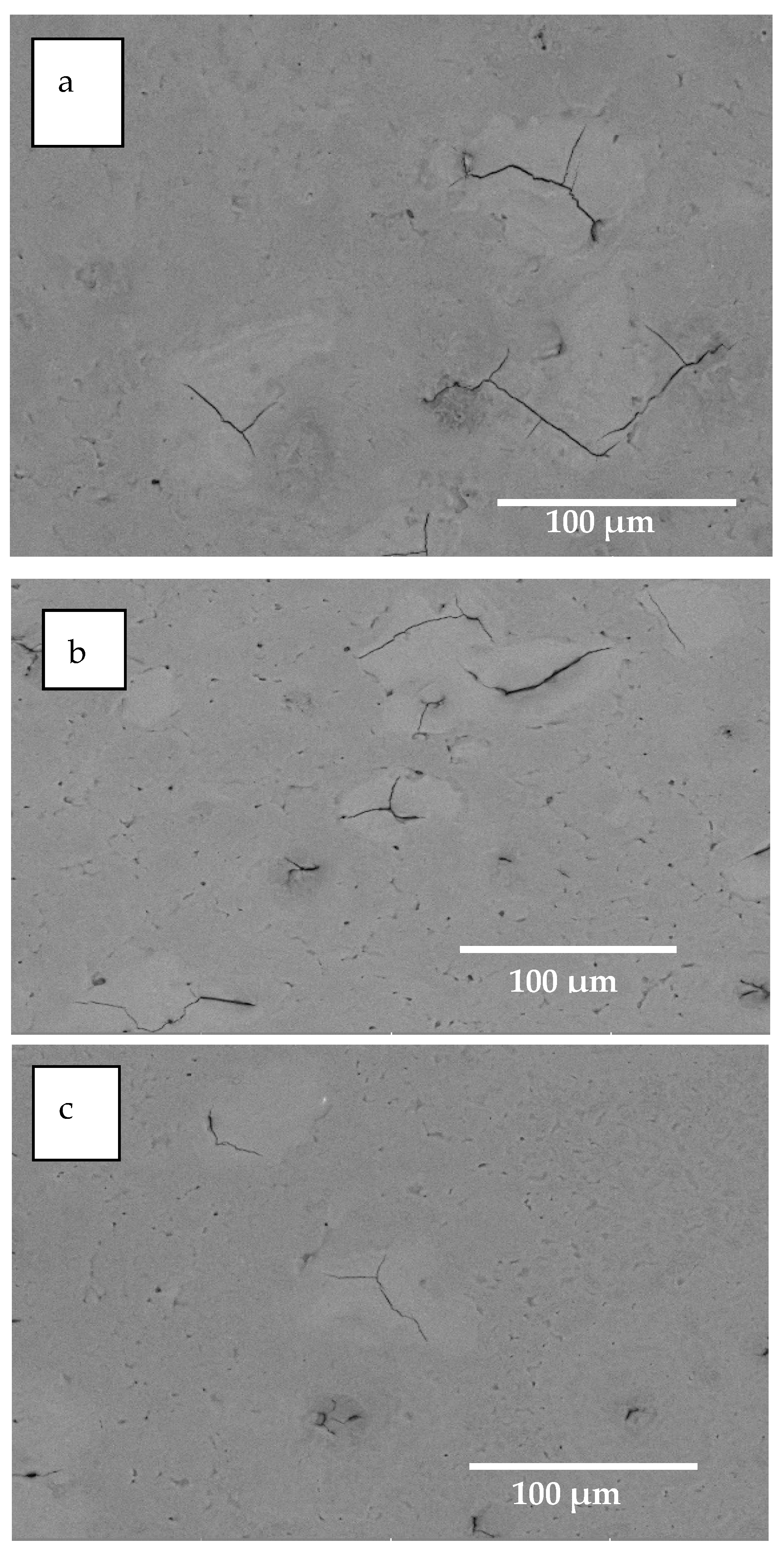
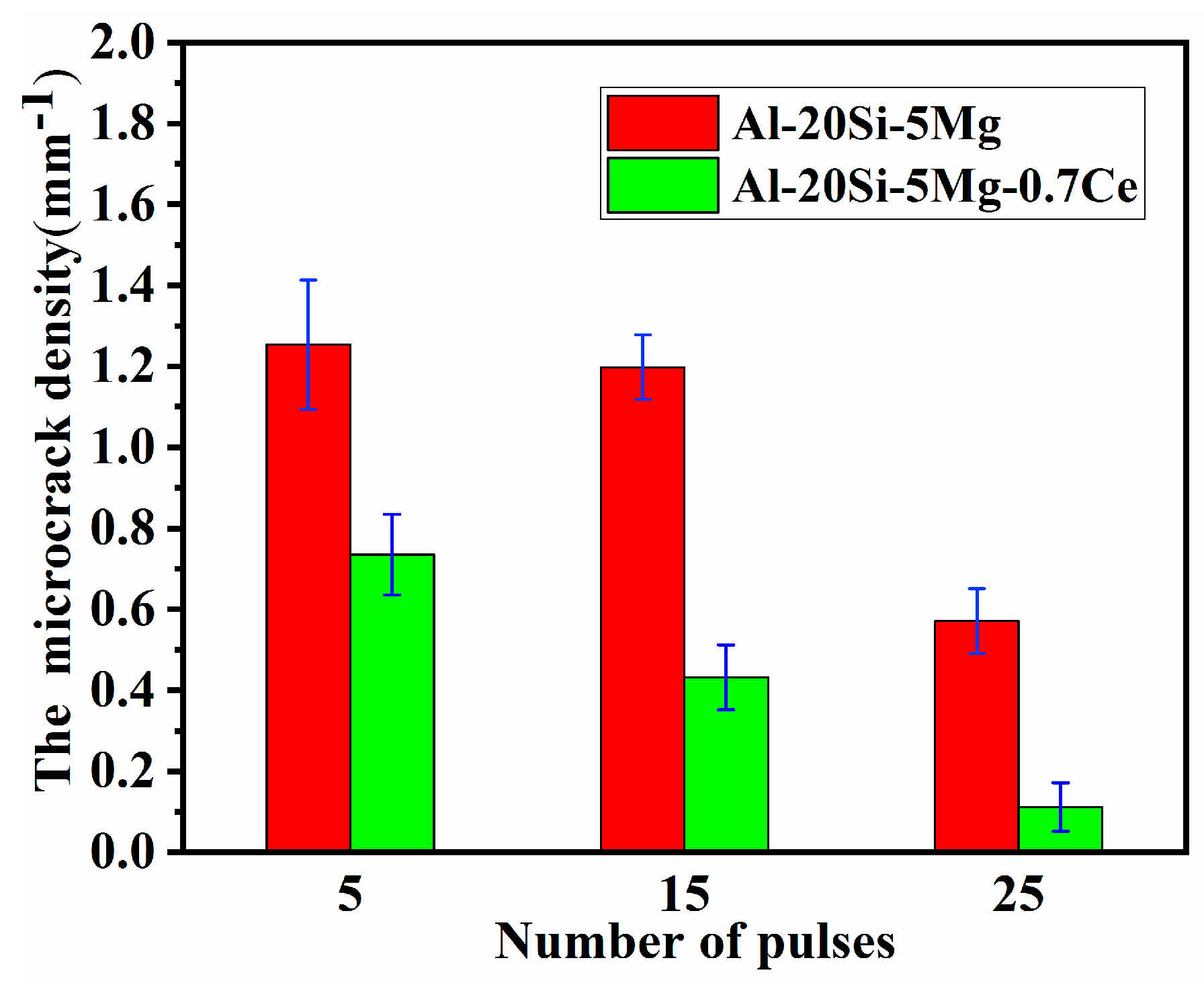
3.2. Microstructure Analysis under HCPEB Irradiation

Earlier studies [36,37,38] have shown that microcracks are readily formed on the surface of HCPEB-irradiated hypereutectic Al–Si alloys without modifying agents, accompanied by the formation of crater structures. The incorporation of appropriate modifying agents (such as RE metal elements) efficiently suppresses the formation of microcracks after HCPEB irradiation. However, Mg has rarely been reported to affect the surface microcracks originating from the HCPEB irradiation. The present study focuses on the effect of Mg on surface microcracks induced by HCPEB in Al–20Si alloys and on the incorporation of Ce into Al–Si–Mg alloys to further improve the resistance to surface microcrack formation.
Figure 3 and Figure 4 show the SEM micrographs of the Al–20Si–5Mg and Al–20Si–5Mg–0.7Ce alloy surfaces irradiated by HCPEB, respectively. As evident in Figure 3, the microcracks appears on the surface of the HCPEB-irradiated Al–20Si–5Mg alloy. Only a small number of microcracks are observed for specimens treated using 25 pulses, implying that Mg efficiently suppresses the propagation of microcracks. However, the surface microcracks cannot be completely eliminated using only Mg. By contrast, small sized microcracks are observed to be exposed on the surface of the HCPEB-irradiated Al–20Si–5Mg–0.7Ce alloy after 15 and 25 pulses (Figure 4b,c), indicating that the addition of Ce almost eliminates the presence of microcracks. These results suggest that the microcracks induced by HCPEB are effectively eliminated by the synergistic effects between Ce and Mg.
In the present study, the microcrack density was adopted as an important indicator to quantify the microcracks induced by HCPEB [1], as shown in Equation (2):
ρ = L/S
where ρ is the microcrack density (mm−1), L is the total microcrack length (mm), and S is the visual field area (mm2). Compared with the Al–20Si alloy specimens without modifying agents (Figures S2 and S3), the density of the microcracks decreased from 1.254 ± 0.16 mm−1 at five pulses to 0.571 ± 0.08 mm−1 at 25 pulses for the alloys with incorporated Mg (Figure 5). However, for the Al–20Si–5Mg–0.7Ce alloy specimens, the microcrack density corresponding to the same number of pulses was substantially lower than for the alloy specimens with incorporated Mg: 0.735 ± 0.1 mm−1 after five pulses and 0.112 ± 0.06 mm−1 after 25 pulses (Figure 5). These results indicate that the combination of Ce and Mg plays a substantial role in eliminating the microcracks as compared with the addition of Mg only.
The synergistic effects of Ce and Mg can be elaborated as follows: The reaction to form the primary Mg2Si phase occurs in the alloy melt because of the presence of Mg, thus consuming a fraction of the Si and refining the primary Si phase in the pristine microstructure. The refinement of the phase shortens the propagation path of the microcracks, thereby hindering microcrack propagation within the brittle phase because of the restricted microcrack extension space, thereby effectively arresting the microcracks. However, Ce can refine the primary Si phase in the pristine microstructure and reduce the local stress concentration within primary Si produced during rapid cooling of the materials, thereby suppressing or eliminating microcrack propagation. Thus, the aforementioned mechanism of microcrack elimination illustrates that the synergistic effects of Mg and Ce could lead to a reduction in the microcrack density with an incremental number of pulses. Notably, however, the elimination of microcracks also depends on the electron beam treatment parameters. Figure S4 shows SEM micrographs of microcrack morphology and associated microcrack density on the Al–20Si–5Mg–0.7Ce alloy surface subjected to HCPEB irradiation at 24 kV and 2 J/cm2. Compared with the alloy specimens irradiated at 27 kV and 4 J/cm2 (Figure 4), numerous microcracks are observed on the alloy surface, and the microcrack density decreases from 1.62 ± 0.08 mm−1 after five pulses to 1.267 ± 0.08 mm−1 for 25 pulses. The result implies that the microcrack propagation is effectively restrained to achieve microcrack arrest rather than microcrack elimination.
As evident in Figure S4a–c, the white Ce-rich intermetallic compound does not completely melt under low-energy irradiation conditions of 24 kV and 2 J/cm2. By contrast, the intermetallic compound completely dissolves in the Al matrix under the high-energy irradiation conditions of 27 kV and 4 J/cm2 (Figure 4). These results imply that the degree of dissolution of the intermetallic compound directly affects the elimination of the microcracks. The complete dissolution of the intermetallic compound indicates that Ce plays a substantial role in eliminating microcracks. If the compound is not completely dissolved, Ce can only induce a microcrack arrest effect. Therefore, the microcrack arrest or elimination can be controlled by adjusting the electron beam treatment parameters, consistent with the microcrack repair achieved by adjusting the accelerating voltage and pulse number of the electron beam, as reported elsewhere [27].
The most important application of surface modification technology based on HCPEB is surface modification of the metallic components such as the blades of the engine and mould. This technology can prolong the service life of these metallic components and improve the surface properties of a material by optimising the surface microstructure. However, microcracks are inevitably introduced on the HCPEB-irradiated material surface, adversely affecting the surface properties and hindering the industrial application of this technology. In the present work, Mg and Ce were incorporated into the Al–20Si alloy to better solve the aforementioned problem. The elimination of microcracks is important for surface modification based on HCPEB, thus facilitating its industrial application.
Figure 6 displays the profile of the alloying elements on the surface of the Al–20Si–5Mg–0.7Ce alloy specimens treated using 25 pulses. As evident in Figure 6a–d, no microcracks are detected in the brittle phase, and Ce is uniformly distributed in the Al matrix of the alloy surface after HCPEB irradiation. These results indicate that the structures vanish at 27 kV and 4 J/cm2 because of the sufficient dissolution of Ce into the Al matrix, leading to the microcrack elimination effect. These findings are consistent with the SEM observations presented in Figure 4b,c, thus verifying that microcrack elimination can be achieved under high-energy conditions. Additionally, a certain degree of aggregation of the Mg is observed in Figure 6e. Furthermore, a small amount of Si exists in the area of Mg aggregation (Figure 6b,e), thus confirming that the area indicated by the white arrow is the Mg2Si phase. Mg and Si tend to diffuse outwards because of the element diffusion effect induced by HCPEB. Essentially, the alloying elements diffuse along the chemical element gradient by virtue of this effect, thus eventually leading to a homogenous distribution of the elements [36,39]. The surface components of the alloys become homogenous at high pulse numbers, thus improving the surface properties of the materials.
In the present study, the metastable structures in the surface layer of the Al–20Si–5Mg–0.7Ce alloy subjected to 25 pulse treatments were characterised by TEM and found to include a nano-primary Si phase, nano-cellular aluminium structure, and nano-Mg2Si phase, as shown in Figure 7. These structures apparently arise from the rapid heating and cooling effects excited by HCPEB irradiation. The nano-primary Si phase surrounded by α-Al phases evolves from the primary Si phase, which is a locally amplified structure of the primary Si phase after HCPEB irradiation (Figure 7a). The formation of this phase can be explained as follows: The rapid heating induced by HCPEB promotes the interdiffusion of Al and Si near the border of the primary Si phase, thus producing a crystal nucleus of primary Si in the molten surface layer. The crystal nucleus subsequently grows within a short time under the high cooling rate induced by HCPEB, resulting in the formation of the nano-primary Si phase [1,40,41]. The formation of this phase is accompanied by the diffusion of Al. The corresponding evidence is that the Al phase exists around the nano-primary Si phase. The diffusion phenomenon of Al has been confirmed elsewhere via SEM and EPMA analyses [36,39]. It is concluded that Al gradually permeates into the primary Si phase because of the rapid heating effect induced by HCPEB. The primary Mg2Si phase in the pristine microstructure is transformed into the nano-Mg2Si phase because of the rapid cooling effect excited by HCPEB. Figure 7b–d display the nano-cellular aluminium structure and nano-Mg2Si phase after 25 pulses. The nano-cellular aluminium structure with sizes ranging from 100 to 200 nm is located in the Al-rich area. In addition, the nano-Si phase with a size of 10 nm precipitates from the grain or subgrain boundary of the Al phase because of the eutectic Si dissolving into Al matrix under the HCPEB irradiation (Figure 7b). Analogously, the nano-Mg2Si phase with particle sizes ranging from 10 to 50 nm precipitates from the grain or subgrain boundary of the Al phase, as shown in the bright- and dark-field images in Figure 7c,d, respectively. The grain refinement can increase the total area of grain boundaries, resulting in enhanced resistance to microcrack propagation, thereby delaying the initiation of microcracks. In addition, in the selected-area electron diffraction patterns in Figure 7a,d, the second or dispersed phases generate a polycrystalline diffraction ring after HCPEB irradiation, thus indicating different crystal orientations. However, the nano-cellular aluminium structures also present single-crystal diffraction spots, implying that the structures can be classified as substructures because of their identical orientations. The formation of the metastable phases contributes to the enhancement of the anticorrosion and tribological properties of the alloy surface.

3.3. Phase Identification

Figure 8 displays the X-ray diffraction (XRD) plots of the Al–20Si–5Mg–0.7Ce alloy specimens as a function of the number of pulses. As evident from Figure 8a, the phase transformation is invisible on the alloy surface irradiated via HCPEB. The phase composition mainly includes the Al, Si, and Mg2Si phases. However, Ce intermetallic compounds are not detected on the alloy surface. After HCPEB bombardment, the Ce intermetallic compounds melt, forming a Ce solid solution in the Al matrix. Because the concentration of this solid solution is far below the detection limit (5 wt.%) of the XRD diffractometer, this phase is invisible. In addition, broadening of the Mg2Si (220), Al (200), and Si (220) peaks between 38° and 52° is identifiable in the XRD plots of the specimens subjected to HCPEB irradiation in Figure 7b (locally magnified image of Figure 7a). Compared with the diffraction peaks of the initial specimen, those of the irradiated specimens first shift to higher angles at five pulses and then to lower angles after 15 and 25 pulses. The broadening of the diffraction peaks indicates the appearance of metastable phases caused by the grain refinement effect on the surface of Al alloy induced by HCPEB, consistent with the TEM analysis reported in Figure 6. The diffraction peaks are shifted to higher angles, which is associated with the formation of the residual compressive stress and supersaturated solid solution in the modified layers. Correspondingly, the shift of the diffraction peaks towards lower angles is attributed to the existence of residual tensile stress [36]. In brief, the observed peak broadening and shifting result from the synergistic effects of residual stresses and grain refinement induced by HCPEB irradiation.

3.4. Corrosion Analysis

The electrochemical polarisation curves corresponding to the surface of the HCPEB-irradiated and HCPEB-unirradiated Al–20Si–5Mg and Al–20Si–5Mg–0.7Ce alloys are displayed in Figure 9. The relevant electrochemical parameters obtained from the curves are presented in Table 2. The Al–20Si–5Mg–0.7Ce alloy specimens exhibit excellent anticorrosion behaviour compared with the Al–20Si–5Mg alloy specimens. The corrosion current density of the Al–20Si–5Mg–0.7Ce alloy specimens shows a remarkable decrease from 15.40 μA/cm2 for the original specimen to 0.01021 μA/cm2 for the specimen subjected to 25 pulses, representing a decrease of three orders of magnitude. The corrosion potential of the alloy specimens also shifts toward more positive potentials with increasing number of pulses, implying that the metal might be stable in the corrosive medium, leading to reduced corrosion. However, for the Al–20Si–5Mg alloy specimens, the corrosion current density value decreases by only one order of magnitude, and the variation of the corrosion potential is consistent with that of the Al–20Si–5Mg–0.7Ce alloy specimens.
The surface morphology of the HCPEB-irradiated alloy surface after electrochemical corrosion tests was investigated to determine the cause of the enhanced anticorrosion performance of the materials. Figure 10 and Figure 11 show the surface morphology of the 25-pulse-treated alloys after the electrochemical corrosion test. For the Al–20Si–5Mg alloy (Figure 10a,b), severe corrosion pits are observed in the brittle phase of the surface layer compared with the uncorroded area indicated by point B. The corrosion tends to develop toward pitting corrosion. The most favourable evidence is that the corrosion pits indicated by point A collapse to form holes. To a certain extent, the alumina film spontaneously generated on the Al alloy surface is resistant to corrosion in the presence of Cl ions, which is confirmed by the detection of O by EDS analysis (Figure 10c,d). Meanwhile, the NaCl solution infiltrates the microcracks, accelerating the pitting corrosion of the alloy surface. In addition, small corrosion pits are clearly identifiable in Figure 10b, demonstrating the occurrence of pitting corrosion on the surface of the HCPEB-treated Al–20Si–5Mg alloy. Although the grain refinement effect excited by HCPEB irradiation improves the anticorrosion behaviour of the alloy surface, the corrosion current density does not substantially increase because microcracks accelerate the pitting corrosion process (Table 2).
The pitting corrosion of Al alloys originated from corrosion pits generated by the destruction of the passivation film in the presence of Cl ions. The internal surface of the corrosion pit was in an active dissolved state once the corrosion pit had formed, having a more negative potential as an active anode. Correspondingly, the external surface of the corrosion pits was still in a passivation state, having a more positive potential as a cathode. Thus, a galvanic corrosion microbattery with a large cathode and a small anode structure was formed between the inside and the outside of the corrosion pits, resulting in a sharp increase in the anode dissolution rate and a rapid increase of the corrosion pit depth. On the contrary, the Al alloy surface outside the corrosion pit was protected by an alumina passivation film. The rapid development of pitting corrosion in the depth direction is extremely destructive. However, for the Al–20Si–5Mg–0.7Ce alloy, the corrosion pits formed in the brittle phase were shallow (Figure 11a). In addition, as evident in Figure 11b (an enlargement of Figure 11a), tiny Si particles were exposed on the surface of the brittle phase because of grain boundaries preferentially corroded by the NaCl solution, indicating the occurrence of intergranular corrosion in the brittle phase. Essentially, the atoms at grain boundaries possess a higher average energy than atoms in the grain interior because of the lattice distortion, which causes the higher grain boundary energy and leaves the atoms in an unstable state. Eventually, the corrosion rate at the grain boundaries in the corrosive medium becomes faster than that in the grain interior, leading to intergranular corrosion. However, in the present work, the occurrence of pitting corrosion is delayed by the microcrack elimination effect of Ce. As a result, the corrosion pits become shallower, indicating less corrosion destruction. In addition, the irregular shrinkage cavity produced after rapid solidification is clearly discernible near the brittle phase (Figure 11b), and no tiny corrosion pits such as those in Figure 10b are observed. These phenomena illustrate that the pitting corrosion is suppressed by the elimination of microcracks by Ce, improving the anticorrosion property of the alloy surface. In addition, a compact and stable passivation film of alumina is formed in the modified surface layer because of the presence of metastable structures (e.g., nanocrystalline structure), thus improving the anticorrosion property of the alloy surface. Therefore, the combined effects of the grain refinement and the microcrack elimination contribute to the improved anticorrosion property of the alloy surface [1,42].

4. Conclusions

The effect of Ce and Mg on the surface microcracks induced via HCPEB irradiation was systematically investigated in this paper. The following conclusions were drawn:
(1)
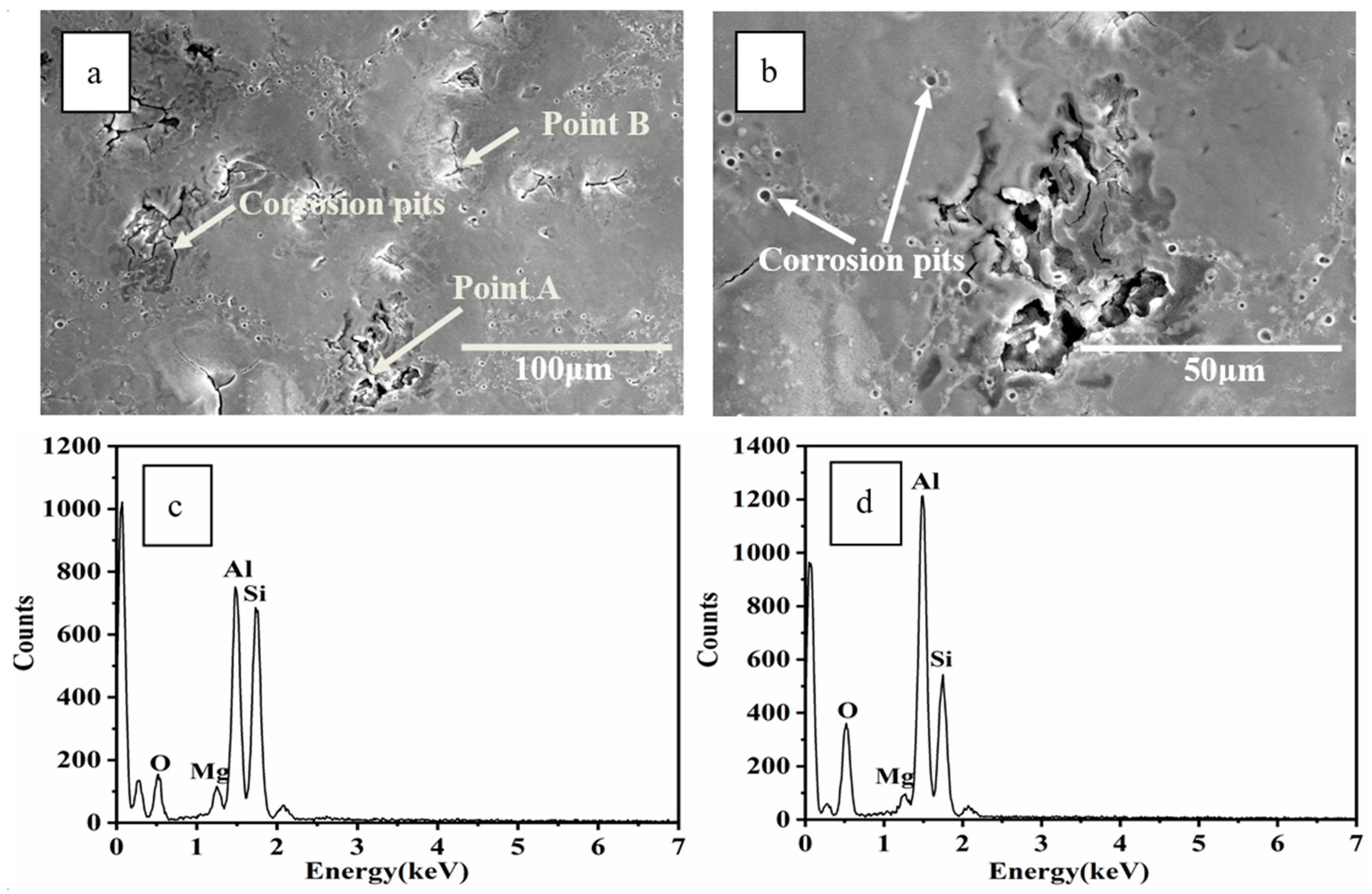
SEM analysis revealed that microcracks in the HCPEB-irradiated Al–20Si alloys were eliminated by the synergistic effect of Ce and Mg. The microcrack elimination was attributed to grain refinement effect of two elements and reduction of the local stress concentration in the brittle phase induced by rare earth Ce.
(2)
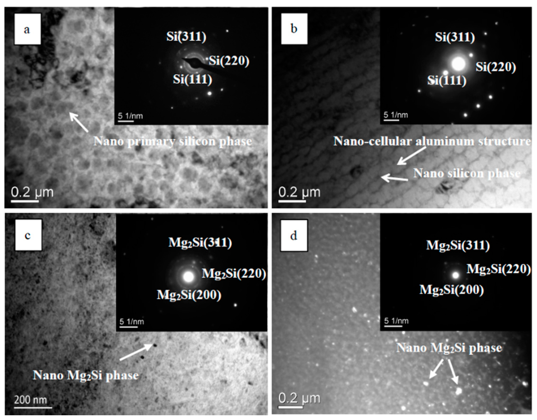
TEM analysis demonstrated that the metastable structures arose because of the rapid heating and solidification effects associated with HCPEB irradiation, which included a nano-primary Si phase, a nano-cellular aluminium structure, and a nano-Mg2Si phase. The formation of these metastable structures implied the grain refinement of the alloy surface, thus resulting in enhanced resistance to microcrack propagation, thereby delaying the initiation of microcracks.
(3)
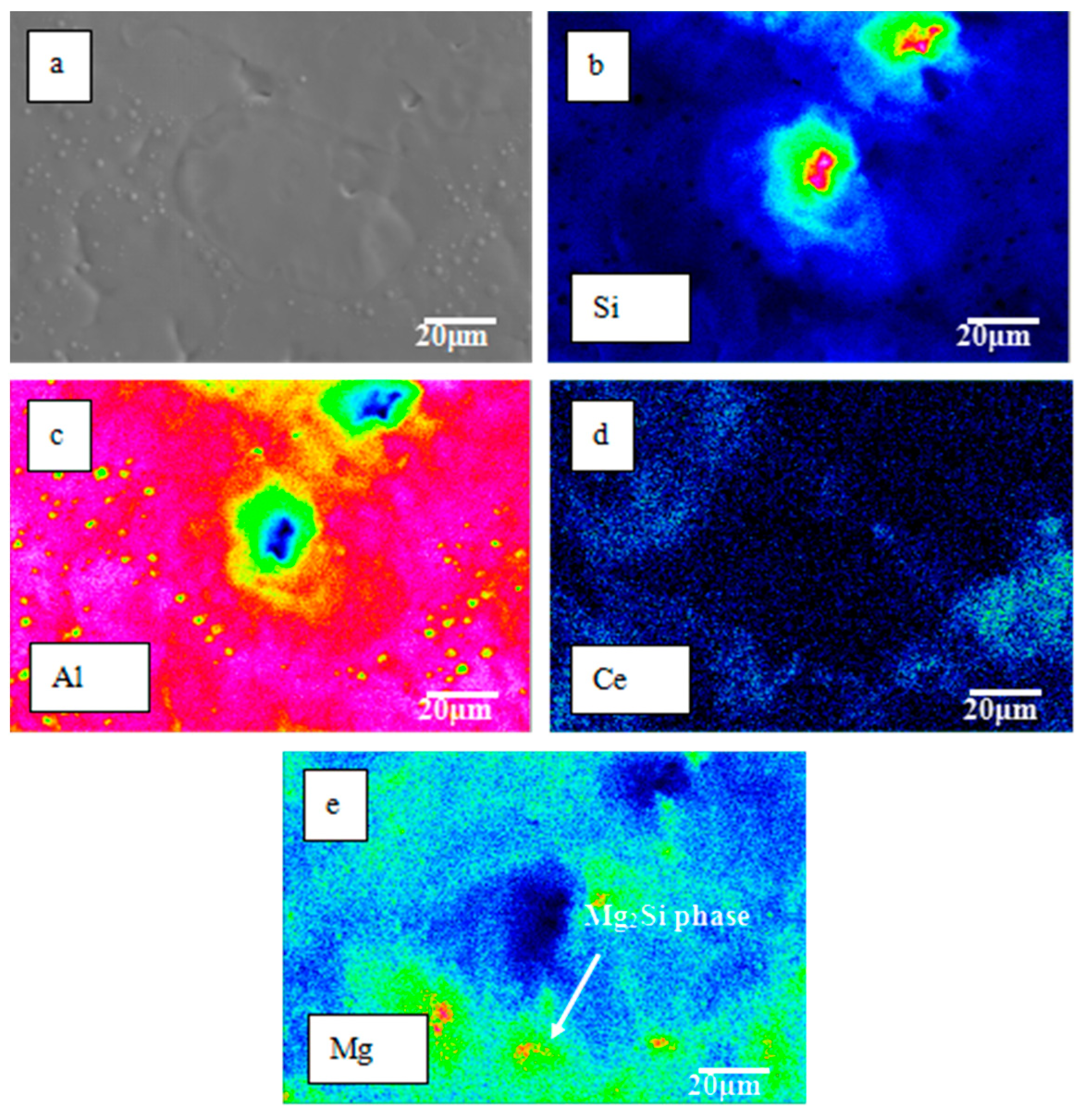
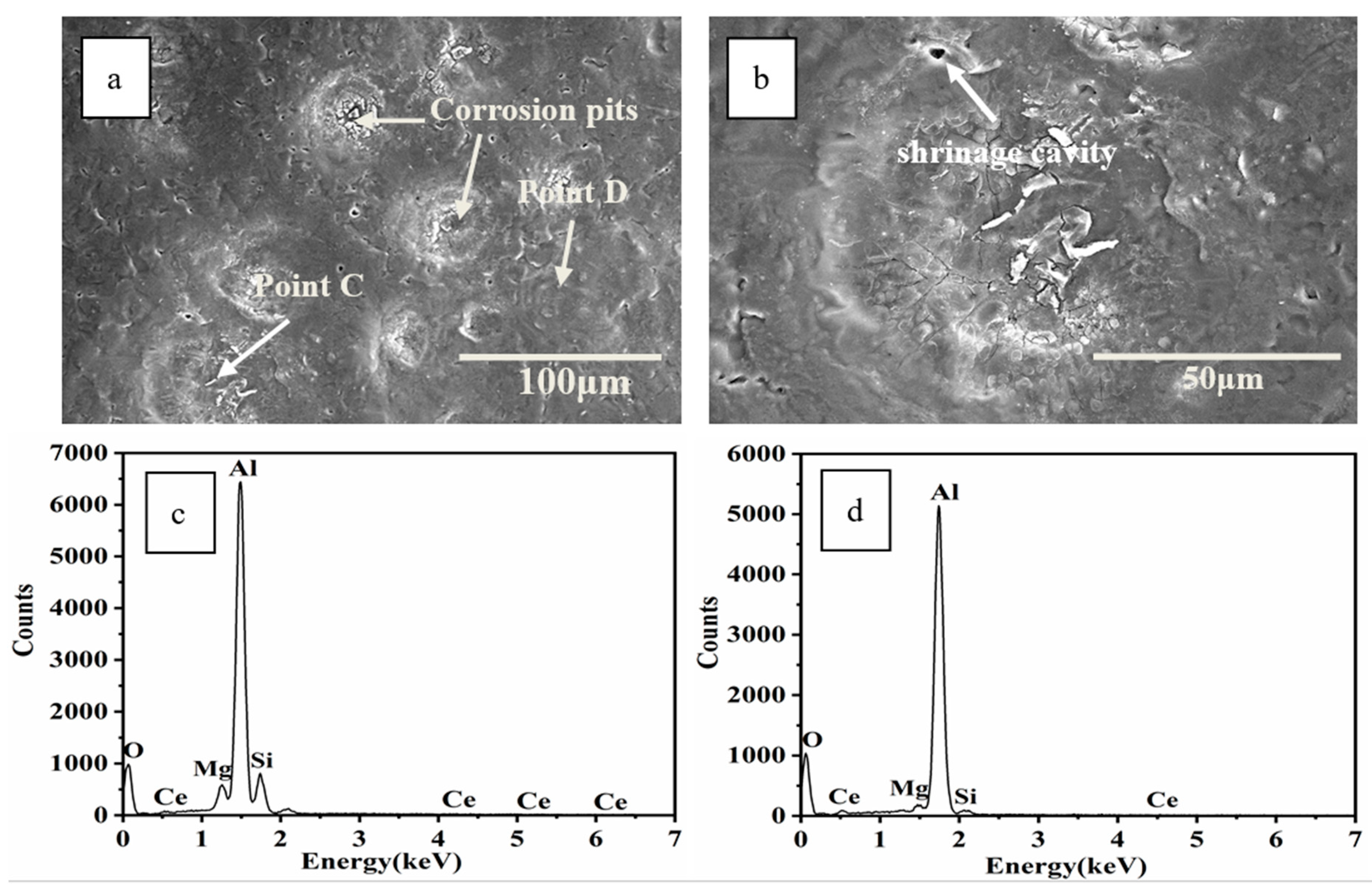
EPMA analysis confirmed the uniform distribution of Ce in the Al matrix on the HCPEB-irradiated alloy surface, implying that Ce was completely dissolved in the phase, thereby significantly contributing to microcrack elimination. Moreover, the Mg and Si exhibited a certain degree of aggregation in the Mg2Si phase.
(4)
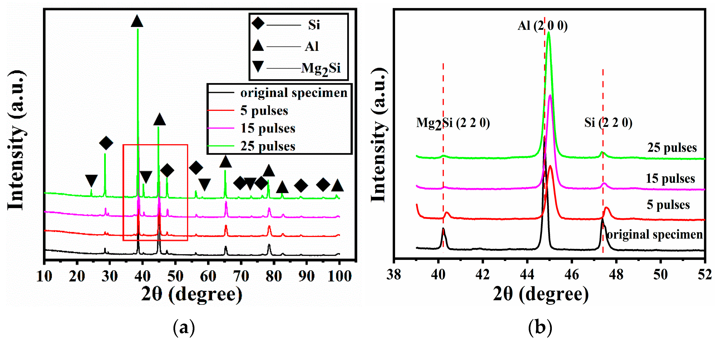
The phase transformation was absent on the HCPEB-irradiated Al–20Si–5Mg–0.7Ce alloy surface, as characterised by XRD analysis, and the phases mainly consisted of Al, Si, and Mg2Si phases. Broadening and shifting of the diffraction peaks was observed because of the formation of metastable structures and the presence of residual stress induced by HCPEB irradiation.
(5)
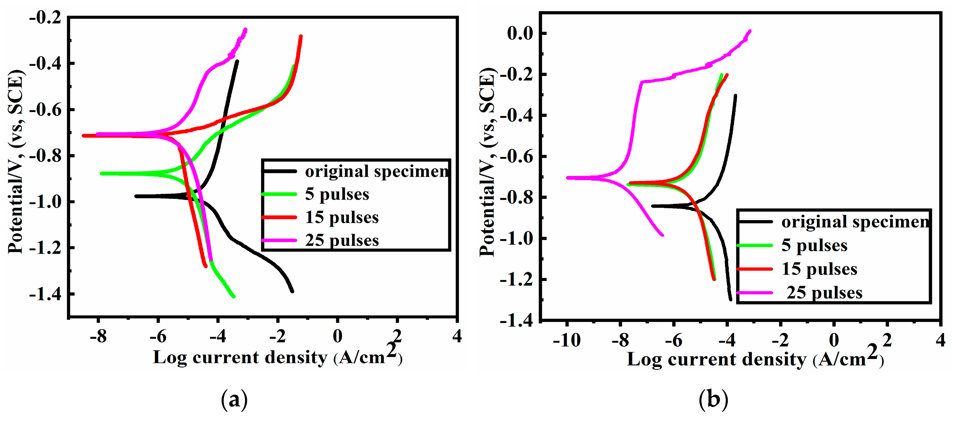
Compared with the alloy specimens containing Mg, the Al–20Si–5Mg–0.7Ce alloy specimens exhibited a superior anticorrosion property after HCPEB irradiation mainly due to the combined effects of the grain refinement and microcrack elimination.

Supplementary Materials

The following are available online at https://www.mdpi.com/article/10.3390/coatings12010061/s1, Figure S1: The SEM morphology micrographs of HCPEB-irradiated and HCPEB-unirradiated Al–20Si–0.3Nd alloy surface. (a) Original specimen; (b) 5 pulse specimen, 27 kV and 4 J/cm2; (c) 15 pulse specimen, 27 kV and 4 J/cm2; (d) 25 pulse specimen, 27 kV and 4 J/cm2, Figure S2: The SEM morphology micrographs of HCPEB-irradiated and HCPEB-unirradiated Al–20Si alloy surface. (a) Original specimen; (b) 5 pulse specimen, 27 kV and 4 J/cm2; (c) 15 pulse specimen, 27 kV and 4 J/cm2; (d) 25 pulse specimen, 27 kV and 4 J/cm2, Figure S3: The relationship between microcrack density and pulse number for Al–20Si and Al–20Si–0.3Nd alloy surfaces under HCPEB irradiation, Figure S4: The SEM morphology micrographs and relevant microcrack density for Al–20Si–5Mg–0.7Ce alloy surface irradiated by HCPEB at 24 kV and 2 J/cm2. (a) BSE image, 5 pulse specimen; (b) BSE image, 15 pulse specimen; (c) BSE image, 25 pulse specimen; (d) Relationship between microcrack density and pulse number.

Author Contributions

Writing—original draft preparation, L.H.; project administration, B.G.; data curation, N.X.; software, Y.S.; validation, Y.Z.; supervision, P.X. All authors have read and agreed to the published version of the manuscript.

Funding

This work was strongly supported by the National Natural Science Foundation of China (51671052), Fundamental Research Funds for the Central Universities (N182502042), and LiaoNing Revitalization Talents Program (XLYC1902105).

Institutional Review Board Statement

Not applicable.

Informed Consent Statement

Not applicable.

Data Availability Statement

Data sharing is not applicable to this article.

Conflicts of Interest

The authors declare no conflict of interest.

References

  1. Hu, L.; Gao, B.; Zhu, G.L.; Hao, Y.; Sun, S.C.; Tu, G.F. The effect of neodymium on the microcracks generated on the Al–17.5Si alloy surface treated by high current pulsed electron beam. Appl. Surf. Sci. 2016, 364, 490–497. [Google Scholar] [CrossRef]
  2. Cai, J.; Li, C.; Yao, Y.M.; Lyu, P.; Guan, Q.F.; Li, Y.X.; Lu, J.Z. Microstructural modifications and high-temperature oxidation resistance of arc ion plated NiCoCrAlYSiHf coating via high-current pulsed electron beam. Corros. Sci. 2021, 182, 109281–109295. [Google Scholar] [CrossRef]
  3. Zhang, C.L.; Tian, N.N.; Li, L.; Yang, Z.R.; Lv, P.; Jin, Y.X.; Zhu, H.J.; Guan, Q.F. The effect of high-current pulsed electron beam on phase formation and surface properties of chromium/copper system. Vacuum 2020, 174, 109222–109232. [Google Scholar] [CrossRef]
  4. Sun, P.P.; Zhang, C.L.; Cai, J.; Lyu, P.; Jin, Y.X.; Guan, Q.F. Properties of a rapidly solidified Ni–Nb layer prepared using a high-current pulsed electron beam. Vacuum 2020, 177, 109362–109370. [Google Scholar] [CrossRef]
  5. Yang, S.; Guo, Z.X.; Zhao, L.; Zhao, L.; Guan, Q.F.; Liu, Y.H. Surface microstructures and high-temperature high-pressure corrosion behavior of N18 zirconium alloy induced by high current pulsed electron beam irradiation. Appl. Surf. Sci. 2019, 484, 453–460. [Google Scholar] [CrossRef]
  6. Zhang, C.L.; Cai, J.; Lv, P.; Zhang, Y.W.; Xia, H.; Guan, Q.F. Surface microstructure and properties of Cu–C powder metallurgical alloy induced by high-current pulsed electron beam. J. Alloys Compd. 2017, 697, 96–103. [Google Scholar] [CrossRef]
  7. Fu, Y.L.; Hu, J.; Zhao, W.S.; Peng, F.J.; Huo, W.J.; Cao, X.T. Microstructure modification and corrosion improvement of AISI1045 steel induced by pseudospark electron beam treatment. Nucl. Instrum. Meth. B 2020, 469, 10–18. [Google Scholar] [CrossRef]
  8. Zhang, K.M.; Ma, J.X.; Zou, J.X.; Liu, Y.R. Surface microstructure and property modifications in a duplex stainless steel induced by high current pulsed electron beam treatments. J. Alloys Compd. 2017, 707, 178–183. [Google Scholar] [CrossRef]
  9. Yan, P.; Zou, J.X.; Zhang, C.L.; Grosdidier, T. Surface modifications of a cold rolled 2024 Al alloy by high current pulsed electron beams. Appl. Surf. Sci. 2020, 504, 144382–144396. [Google Scholar] [CrossRef]
  10. Konovalov, S.; Zaguliaev, D.; Ivanov, Y.; Gromov, V.; Abaturova, A. Modification of Al–10Si–2Cu alloy surface by intensive pulsed electron beam. J. Mater. Res. Technol. 2020, 9, 5591–5598. [Google Scholar] [CrossRef]
  11. Zhang, X.; Zhang, K.M.; Zou, J.X.; Yan, P.; Song, L.X.; Liu, Y.R. Surface microstructure modifications and in-vitro corrosion resistance improvement of a WE43 Mg alloy treated by pulsed electron beams. Vacuum 2020, 173, 109132–109140. [Google Scholar] [CrossRef]
  12. Morini, F.; Bestetti, M.; Franz, S.; Vicenzo, A.; Markov, A.; Yakovlev, E. Surface properties modification of magnesium alloys by low energy high current pulsed electron beam. Surf. Coat. Technol. 2021, 420, 127351–127362. [Google Scholar] [CrossRef]
  13. Meisner, L.L.; Semin, V.O.; Mironov, Y.P.; Meisner, S.N.; D’yachenko, F.A. Cross-sectional analysis of the graded microstructure and residual stress distribution in a TiNi alloy treated with low energy high-current pulsed electron beam. Mater. Today Commun. 2018, 17, 169–179. [Google Scholar] [CrossRef]
  14. Semin, V.O.; Meisner, L.L. Atomic structure of an amorphous Ti–Ta-based surface alloy synthesized on a TiNi substrate by an electron-beam method. Appl. Surf. Sci. 2019, 491, 411–419. [Google Scholar] [CrossRef]
  15. Yang, S.; Guo, Z.X.; Zhao, L.; Guan, Q.F.; Zhao, L.; Liu, Y.H. Microstructures and corrosion resistance of Zircaloy-4 after surface alloying with copper by high-current pulsed electron beam. Appl. Surf. Sci. 2020, 501, 144222–144230. [Google Scholar] [CrossRef]
  16. Yang, S.; Guo, Z.X.; Zhang, M.; Guan, Q.F.; Jin, Y.X.; Liu, Y.H. Effect of high current pulsed electron beam surface irradiation on the microstructure and electrochemical behavior of zircaloy-4. Nucl. Instrum. Meth. B 2018, 434, 81–87. [Google Scholar] [CrossRef]
  17. Zhou, Z.M.; Chai, L.J.; Xiao, Z.P.; Tu, J.; Wang, Y.P.; Huang, W.J. Surface modification of Cu–25Cr alloy induced by high current pulsed electron beam. Trans. Nonferr. Metal. Soc. 2015, 25, 1935–1943. [Google Scholar] [CrossRef]
  18. Peng, W.H.; Hao, S.Z.; Zhao, L.M.; Chen, J.; Li, W. Formation mechanism of graphite nanospheres in W–C–Co system under high current pulsed electron beam irradiation. Mater. Lett. 2019, 244, 207–210. [Google Scholar] [CrossRef]
  19. Zhang, F.G. Friction and wear behavior of WC/Ni cemented carbide tool material irradiated by high-intensity pulsed electron beam. Ceram. Int. 2019, 45, 15327–15333. [Google Scholar] [CrossRef]
  20. Cai, J.; Yao, Y.M.; Wei, J.Z.; Guan, Q.F.; Lyu, P.; Ye, Y.X.; Li, Y.X. Microstructure and transient oxidation behavior of NiCoCrAlYSiHf coating modified via high-current pulsed electron beam. Surf. Coat. Technol. 2021, 422, 127499–127510. [Google Scholar] [CrossRef]
  21. Cai, J.; Zu, Z.K.; Li, C.; Lyu, P.; Guan, Q.F.; Li, Y.X. Hot corrosion behavior of arc ion plating NiCoCrAlYSiHf coating via high--current pulsed electron beam. Oxid. Met. 2020, 94, 569–586. [Google Scholar] [CrossRef]
  22. Zhang, F.G. Tungsten carbide phase transformation under non-equilibrium solidification of high intensity pulsed ion and electron beams. Vacuum 2019, 159, 254–260. [Google Scholar]
  23. Golovin, Y.I.; Finkel, V.M.; Sletkov, A.A. Effects of current pulses on crack propagation kinetics in silicon iron. Strength Mater. 1977, 9, 204–210. [Google Scholar] [CrossRef]
  24. Finkel, V.M.; Ivanov, V.M.; Golovin, Y.I. Crack healing in metals by crossed electric and magnetic fields. Strength Mater. 1983, 15, 501–506. [Google Scholar] [CrossRef]
  25. Fu, Y.M.; Bai, X.Z.; Qiao, G.Y.; Hu, Y.D. Technique for producing crack arrest by electromagnetic heating. Mater. Sci. Technol.-Lond. 2001, 17, 1653–1656. [Google Scholar] [CrossRef]
  26. Fu, Y.M.; Bai, X.Z.; Zheng, L.J. Numerical simulation and experimental research on crack arresting using electromagnetic heat effects. Int. J. Nonlin. Sci. Num. 2001, 2, 375–378. [Google Scholar] [CrossRef]
  27. Murray, J.W.; Clare, A.T. Repair of EDM induced surface cracks by pulsed electron beam irradiation. J. Mater. Process. Technol. 2012, 212, 2642–2651. [Google Scholar] [CrossRef]
  28. Li, Q.L.; Xia, T.D.; Lan, Y.F.; Zhao, W.J.; Fan, L.; Li, P.F. Effect of rare earth cerium addition on the microstructure and tensile properties of hypereutectic Al–20%Si alloy. J. Alloys Compd. 2013, 562, 25–32. [Google Scholar] [CrossRef]
  29. Huang, Z.L.; Wang, K.; Zhang, Z.M.; Li, B.; Xue, H.S.; Yang, D.Z. Effects of Mg content on primary Mg2Si phase in hypereutectic Al–Si alloys. Trans. Nonferr. Metal. Soc. 2015, 25, 3197–3203. [Google Scholar] [CrossRef]
  30. Ma, P.; Wei, Z.J.; Jia, Y.D.; Zou, C.M.; Scudino, S.; Prashanth, K.G.; Yu, Z.S.; Yang, S.L.; Li, C.G.; Eckert, J. Effect of high pressure solidification on tensile properties and strengthening mechanisms of Al–20Si. J. Alloys Compd. 2016, 688, 88–93. [Google Scholar] [CrossRef]
  31. Shi, W.X.; Gao, B.; Tu, G.F.; Li, S.W. Effect of Nd on microstructure and wear resistance of hypereutectic Al–20Si alloy. J. Alloys Compd. 2010, 508, 480–485. [Google Scholar] [CrossRef]
  32. Raghavan, V. Al-Mg-Si (Aluminum-Magnesium-Silicon). J. Phase Equilib. Diff. 2007, 28, 189–191. [Google Scholar] [CrossRef]
  33. Akrami, A.; Nasiri, N.; Kulish, V. Fractal dimension analysis of Mg2Si particles of Al-15% Mg2Si composite and its relationships to mechanical properties. Results Mater. 2020, 7, 100118–100123. [Google Scholar] [CrossRef]
  34. Ganiger, B.; Chandrashekharaiah, T.M.; Prasad, T.B.; Kabadi, V.R. Studies on relationship between wear behaviour and microstructure of a hypereutectic Al–Si alloy. Mater. Today Proc. 2018, 5, 25165–25173. [Google Scholar] [CrossRef]
  35. Li, Q.L.; Xia, T.D.; Lan, Y.F.; Li, P.F.; Fan, L. Effects of rare earth Er addition on microstructure and mechanical properties of hypereutectic Al–20% Si alloy. Mater. Sci. Eng. A 2013, 588, 97–102. [Google Scholar] [CrossRef]
  36. Hao, Y.; Gao, B.; Tu, G.F.; Li, S.W.; Dong, C.; Zhang, Z.G. Improved wear resistance of Al–15Si alloy with a high current pulsed electron beam treatment. Nucl. Instrum. Meth. B 2011, 269, 1499–1505. [Google Scholar] [CrossRef]
  37. Hao, Y.; Gao, B.; Tu, G.F.; Li, S.W.; Hao, S.Z.; Dong, C. Surface modification of Al–20Si alloy by high current pulsed electron beam. Appl. Surf. Sci. 2011, 257, 3913–3919. [Google Scholar] [CrossRef]
  38. Gao, B.; Hao, Y.; Zhuang, W.F.; Tu, G.F.; Shi, W.X.; Li, S.W.; Hao, S.Z.; Dong, C.; Li, M.C. Study on continuous solid solution of Al and Si elements of a high current pulsed electron beam treated hypereutectic Al17.5Si alloy. Phys. Procedia 2011, 18, 187–192. [Google Scholar] [CrossRef] [Green Version]
  39. Hu, L.; Gao, B.; Lv, J.K.; Sun, S.C.; Hao, Y.; Tu, G.F. Halo evolution of hypereutectic Al–17.5Si alloy treated with high-current pulsed electron beam. J. Nanomater. 2015, 2015, 247. [Google Scholar] [CrossRef] [Green Version]
  40. Gao, B.; Hu, L.; Li, S.W.; Hao, Y.; Zhang, Y.D.; Tu, G.F.; Grosdidier, T. Study on the nanostructure formation mechanism of hypereutectic Al–17.5Si alloy induced by high current pulsed electron beam. Appl. Surf. Sci. 2015, 346, 147–157. [Google Scholar] [CrossRef]
  41. Gao, B.; Li, K.; Xing, P.F. Formation of a double-layer ultrafine crystal structure for high-current pulsed electron beam-treated Al–20Si–5Mg alloy. Coatings 2019, 9, 413. [Google Scholar] [CrossRef] [Green Version]
  42. Li, K.; Gao, B.; Xu, N.; Sun, Y.; Denisov, V.V.; Hu, L. The Influence of neodymium element on the crater structure formed on Al–17.5Si alloy surface processed by high-current pulsed electron beam. Coatings 2020, 10, 922. [Google Scholar] [CrossRef]
Figure 1. SEM morphology micrographs of Al–20Si–5Mg and Al–20Si–5Mg–0.7Ce alloy surfaces without HCPEB irradiation. (a) SE image, Al–20Si–5Mg; (b) BSE image, Al–20Si–5Mg–0.7Ce; (c) magnified micrograph of Figure 1b; (d) EDS results of Ce-rich intermetallic compound in Figure 1c.
Coatings 12 00061 g001
Figure 2. The phase diagram of Al–Mg–Si computed vertical section [32]. Copyright 2007 Springer.
Coatings 12 00061 g002
Figure 3. SEM morphology micrographs of the Al–20Si–5Mg alloy surface irradiated using HCPEB. (a) 5 pulse specimen, BSE image; (b) 15 pulse specimen, BSE image; (c) 25 pulse specimen, BSE image.
Coatings 12 00061 g003
Figure 4. SEM morphology micrographs of the Al–20Si–5Mg–0.7Ce alloy surface irradiated using HCPEB. (a) 5 pulse specimen, BSE image; (b) 15 pulse specimen, BSE image; (c) 25 pulse specimen, BSE image.
Coatings 12 00061 g004
Figure 5. Relationship between microcrack density and pulse number of HCPEB-irradiated Al–20Si–5Mg and Al–20Si–5Mg–0.7Ce alloy surfaces.
Coatings 12 00061 g005
Figure 6. EPMA images of the 25-pulse treated Al–20Si–5Mg–0.7Ce alloy surface. (a) SE image; (b) elemental profile of Si; (c) elemental profile of Al; (d) elemental profile of Ce; (e) elemental profile of Mg.
Coatings 12 00061 g006
Figure 7. TEM micrographs of the Al–20Si–5Mg–0.7Ce alloy surface irradiated using HCPEB with 25 pulse treatments. (a) Nano-primary silicon phase; (b) nano-cellular aluminium structure and tiny nano-silicon phase; (c) nano-Mg2Si phase; (d) dark-field image of the nano-Mg2Si phase.
Coatings 12 00061 g007
Figure 8. XRD plots of HCPEB-irradiated and HCPEB-unirradiated Al–20Si–5Mg–0.7Ce alloy surface. (a) Entire XRD plot; (b) enlarged plot of the Mg2Si(220), Al(200), and Si(220) peaks.
Coatings 12 00061 g008
Figure 9. Electrochemical polarisation curves of HCPEB-irradiated and HCPEB-unirradiated Al–20Si–5Mg and Al–20Si–5Mg–0.7Ce alloy surfaces. (a) Al–20Si–5Mg alloy; (b) Al–20Si–5Mg–0.7Ce alloy.
Coatings 12 00061 g009
Figure 10. Surface morphology of 25-pulse-treated Al–20Si–5Mg alloy surfaces after electrochemical corrosion testing. (a) Low magnification micrograph; (b) high magnification micrograph, enlarged micrograph of Figure 10a; (c) EDS profile of point A in Figure 10a; (d) EDS profile of point B in Figure 10a.
Coatings 12 00061 g010
Figure 11. Surface morphology of 25-pulse-treated Al–20Si–5Mg–0.7Ce alloy surfaces after electrochemical corrosion testing. (a) Low magnification micrograph; (b) high magnification micrograph, enlarged micrograph of Figure 11a; (c) EDS profile of point C in Figure 11a; (d) EDS profile of point D in Figure 11a.
Coatings 12 00061 g011
Table 1. Chemical ingredients of hypereutectic Al–Si alloys (wt.%).
AlloysAlSiMgCeImpurity
Al–20Si–5Mg alloy75.0620.054.79≤0.1
Al–20Si–5Mg–0.7Ce alloy75.0119.544.690.66≤0.1
Table 2. Electrochemical parameters obtained in electrochemical analysis.
Alloy SampleHCPEB PulsesEcoor (mV)Icorr (μA/cm2)
Al–20Si–5Mg alloy0−972.852.88
5−875.07.745
15−726.54.756
25−710.33.965
Al–20Si–5Mg–0.7Ce alloy0−847.215.40
5−758.42.798
15−727.92.459
25−707.70.01021
Publisher’s Note: MDPI stays neutral with regard to jurisdictional claims in published maps and institutional affiliations.

