Article

Controlled Electroplating of Noble Metals on III-V Semiconductor Nanotemplates Fabricated by Anodic Etching of Bulk Substrates

by
Elena I. Monaico
1,
Eduard V. Monaico
1,*,
Veaceslav V. Ursaki
1,2 and
Ion M. Tiginyanu
1,2
1
National Center for Materials Study and Testing, Technical University of Moldova, 2004 Chisinau, Moldova
2
Academy of Sciences of Moldova, 2001 Chisinau, Moldova
*
Author to whom correspondence should be addressed.
Coatings 2022, 12(10), 1521; https://doi.org/10.3390/coatings12101521
Submission received: 25 September 2022 / Revised: 5 October 2022 / Accepted: 7 October 2022 / Published: 11 October 2022
(This article belongs to the Special Issue Electrochemical Deposition: Properties and Applications)

Abstract

:
Porous templates are widely used for the preparation of various metallic nanostructures. Semiconductor templates have the advantage of controlled electrical conductivity. Site-selective deposition of noble metal formations, such as Pt and Au nanodots and nanotubes, was demonstrated in this paper for porous InP templates prepared by the anodization of InP wafers. Metal deposition was performed by pulsed electroplating. The produced hybrid nanomaterials were characterized by scanning electron microscopy (SEM) and energy dispersive X-ray analysis (EDX). It was shown that uniform deposition of the metal along the pore length could be obtained with optimized pulse parameters. The obtained results are discussed in terms of the optimum conditions for effective electrolyte refreshing and avoiding its depletion in pores during the electroplating process. It was demonstrated that the proposed technology could also be applied for the preparation of metal nanostructures on porous oxide templates, when it is combined with thermal treatment for the oxidation of the porous semiconductor skeleton.

1. Introduction

Over recent decades, the synthesis of functional nanomaterials has been a topic of interest due to their wide area of potential application in electronics, optoelectronics, photonics, magnetic devices, thermal energy storage, thermal transport, electrochromic windows, photovoltaic cells, biotechnology and life sciences, metallic building blocks in the form of nanowires, nanotubes and arrangements of nanoparticles, among others [1,2,3,4,5,6,7]. One of the main methods for the preparation of such structures is template synthesis, template electrodeposition being one of the most general approaches for the control of size, shape and structural properties of metallic nanostructures [8,9,10].
Apart from growing polycrystalline nanowires and nanotubes, single crystal metallic nanostructures can be achieved by controlling the electroplating parameters [8], electrodeposition being a cost-effective technique. Concerning the templates, etched ion track membranes based either on inorganic materials or on organic polymers [11,12], and porous alumina templates produced by anodization of aluminum foils [9,10,13,14,15], are the most widely used methods for nanofabrication purposes. Porous alumina templates are of special interest, because they can be produced with periodic arrangement of pores, thus, allowing the fabrication of periodically ordered metallic nanostructures, which enhances their use in device applications. High electrical resistivity is an essential drawback of porous alumina templates, which require additional functionalization of the inner surface of pores before electroplating metals, in order to produce metallic nanotubes. This drawback is overcome in semiconductor porous templates, due to the possibilities of controlling their conductivity. Porous templates have been demonstrated on Si, GaAs, GaP, InP, ZnSe and other semiconductors, including those with an ordered arrangement of pores or with pores of specific shape [16,17]. Nevertheless, uniform deposition of metals inside porous templates remains a challenge. Pulsed electrodeposition has been proposed instead of direct current (DC) electroplating to address this issue [17,18,19,20,21].
The comparative study of continuous current and pulsed electrodeposition of metals on flat substrates revealed some advantages of pulsed electrodeposition, related to superior quality due to reduced contamination by impurities and a lower rate of occluded gases [22,23], as well as smaller grain size at the long pause between pulses due to the larger number of nucleation sites [22,23]. Pulsed electrodeposition is even more promising for porous templates, especially those with pore diameters below 100 nm; since uniform deposition inside pores with continuous current deposition is hardly achievable, a thorough optimization of current pulse parameters being necessary to reach this goal [17,21].
Apart from the templated growth of various metallic nanostructures, randomly oriented porous metallic formations (for instance, nanoporous gold) can be produced by localized electrochemical dealloying [24]. While ordered templated growth is more often applied in electronics, optoelectronics and photonics, dealloying can be applied in high-strength material, catalysis, energy storage or biosensors. Atomically smooth starting surfaces prepared by sputter-annealing cycles in ultrahigh vacuum are usually needed to control the process of dealloying, while the electrochemical preparation of semiconductor porous templates for metal electrodeposition is less sensitive to the surface state, since the pore nucleation layer is removed after anodization. Moreover, while dealloying strongly depends on the crystallographic substrate orientation, the crystallographic orientation of the semiconductor substrate is important only for the growth of crysto pores, while the growth of current line-oriented pores is independent of the crystallographic orientation of the substrate [17].
Recently, an enhancement of the photocatalytic performances of aero-Ga2O3 induced by functionalization with noble metals, was demonstrated [25]. Due to the fact that gallium oxide exhibits high electrical resistivity, functionalization with noble metals via electrochemical deposition is challenging. In their study, the authors used an approach based on a template composed of a network of ZnO microtetrapods. The technological process consisted of four technological steps. In the first step, sputtering of gold was achieved on commercially available ZnO microtetrapods. In the second stage, a film of GaN was grown by hydride vapor phase epitaxy (HVPE) on Au-functionalized ZnO microtetrapods. In the process of HVPE growth of GaN, a simultaneous etching of ZnO occurred, which resulted in the formation of hollow GaN microtubes with the inner surface decorated by Au. At the third step, functionalization with Au of the outer surface of the GaN microtubes was obtained via sputtering. At the end, the GaN/Au microtubes were subjected to thermal annealing for transformation into aero-Ga2O3/Au. However, it should be noted that uniform sputtering in the depth of the template is difficult to achieve. Apart from that, this technological process is too complex. In this paper, we propose a feasible cost-effective approach allowing uniform functionalization of an array of Ga2O3 nanowires with Au nanodots. The technological process consists of electrochemical deposition of Au nanodots on a template of GaAs nanowires produced by anodization of bulk GaAs substrates, followed by oxidation of GaAs nanowires via their thermal annealing.
Pt and Au decorated templates could be promising for the development of micro-engines or micro-submarines with cargo capabilities and enhanced photocatalytic performances [26].
The goal of this paper is to demonstrate controlled electrodeposition of metals into different parts of porous InP templates by adjusting the parameters of the voltage pulses.

2. Materials and Methods

2.1. Anodization

Crystalline 500-μm thick n-InP(100) and n-GaP(100) substrates with a free electron concentration of 1.3 × 1018 cm−3 and 2 × 1017 cm−3, respectively, were supplied by CrysTec GmbH, Germany. Si-doped (111)B-oriented n-type GaAs wafers with a free electron concentration of 2 × 1018 cm−3 were acquired from Mateck GmbH, Jülich, Germany. The samples, with an electrical contact of a silver paste, were pressed against an O-ring in a Teflon cell, as shown in Figure 1. The electrochemical etching was carried out at room temperature in 3.5M NaCl and 1M HBr electrolytes at applied potentials (U) of 6 V and 15 V, respectively, in three electrode configurations, with a Pt mesh with the surface area of 6 cm2 acting as a counter electrode. A saturated Ag/AgCl reference electrode, and the sample as working electrode, were used. For the purpose of obtaining GaAs nanowires, the anodization was conducted on Si-doped (111)B-oriented n-type GaAs wafers in 1M HNO3 electrolyte at an applied potential of 4 V for 20 min. The potentiostat ELIPOR-2 (ET&TE Etch and Technology GmbH, Kiel, Germany) was fully controlled via a PC unit. The steering of the electrolyte was provided by a Teflon agitator connected to a motor. The rotation speed of 100 r·min−1 was controlled by the applied potential from an external multichannel power supply McPower LAB-2305 (ETT Marketing GmbH, Braunschweig, Germany) to the motor.
The morphology and chemical composition analyses of the porous semiconductor templates were investigated using Zeiss (Jena, Germany) Sigma and Tescan (Brno, Czech Republic) Vega TS 5130 MM scanning electron microscopes (SEM), equipped with an Oxford Instruments (Oxford, UK) INCA Energy EDX system operated at 20 kV.

2.2. Electroplating

For opening the entrance in pores after porosification, the top nucleation layer of porous InP samples was removed using isotropic wet etching by immersing of the specimens in HCl:H3PO4 electrolyte with a ratio of 1:1 for 25 s (T = 23 °C). The removal of the top irregular porous layer in GaP was conducted in a mixture of HCl:HNO3:H2O (1:2:2) at 60 °C for 10 min in a well-ventilated fume-hood. The samples were immersed in the deposition electrolyte for 3 min prior to electrodeposition with the purpose of allowing the penetration of the metal ions inside the pores. Pulsed electrochemical deposition of Au and Pt was obtained in a commercially available gold bath containing 5 g·L−1 Au or 5 g·L−1 Pt (DODUCO GmbH, Pforzheim, Germany). The electrochemical deposition was performed at a temperature of 25 °C in a common two-electrode plating cell where the porous sample served as a working electrode, while a platinum wire was used as a counter electrode (Figure 1). A home-made generator capable of providing rectangular pulses with a pulse width (ton) from 500 ns up to 10 s, and delay between pulses (toff) up to 10 s, was used for electroplating. Metal nanodots, nanowires or nanotubes were deposited depending on the applied pulse width, voltage pulse amplitude (U), and electroplating duration, as illustrated in Figure 1. After electroplating, the samples were rinsed in distilled water.

3. Results and Discussion

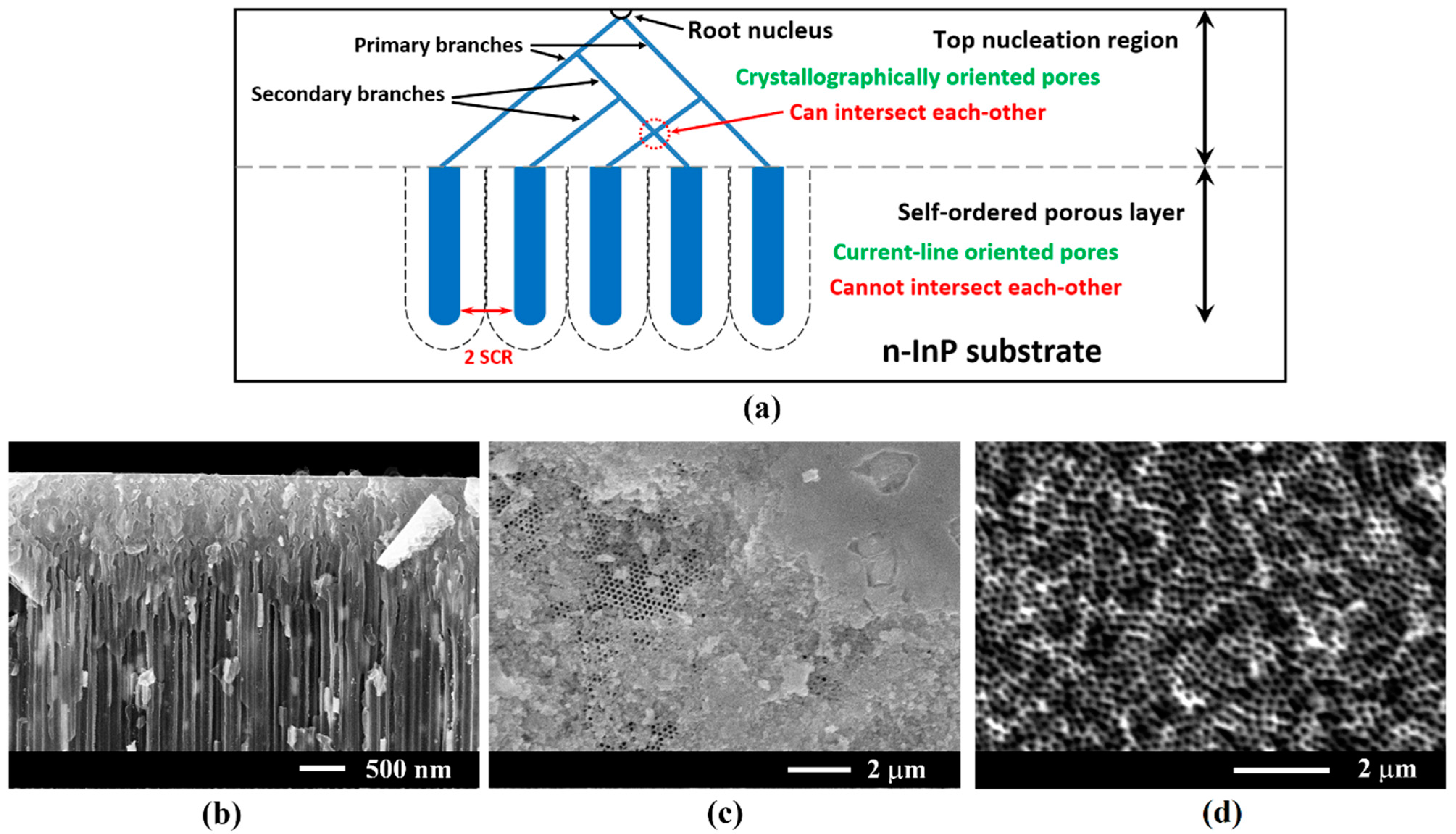
The behavior of the electrochemical dissolution of semiconductor compounds governed by the breakdown mechanism, as well the type of pores obtained as a result of anodization, were reported in our review paper [17]. Briefly, the pore formation mechanism can be explained as follows: by applying the positive potential to the semiconductor, the holes start to drift towards the semiconductor–electrolyte interface (SEI). For n-type semiconductors, the holes are minority carriers. As a result, the anodic current remains low. With a further increase in the applied potential, at a certain potential, depending on the doping and defect density, an increase in current is usually observed in the current–voltage (I-V) characteristic [21]. This increase is related to the avalanche process in the space charge region (SCR). Usually, the anodic dissolution starts at surface defects (dislocations) marked as the root nucleus in Figure 2a. With further increase in the applied voltage, new electron–hole pairs will be generated as a result of multiple collisions of electrons tunneling through the SCR with the atoms. Once new electro–hole pairs are generated due to the breakdown, the etching around the defect will develop through branching of crystallographically oriented pores. At the next stage of anodization, the branching of pores stops, and the current line-oriented pores start to grow in perpendicular alignment to the substrate surface. It should be mentioned that current line-oriented pores cannot intersect each other, therefore, conditions are provided for the self-ordering of pores [17].
Electroplating of Pt on porous InP samples immediately after the electrochemical etching resulted in non-uniform deposition of nanotubes due to the top nucleation layer, as can be seen in Figure 2b. After a certain time, the pores in the nucleation layer were blocked with the deposited metal, which prevented the flow of the electrolyte into the full depth of the pores. Usually, the thickness of the nucleation layer in samples with a concentration of 1018 cm−3 was up to 2 µm.
In connection with this, removal of the nucleation layer is an important technological step to achieve a uniform deposition along the whole depth of the porous layer. Figure 2c discloses the evolution of the nucleation layer and emergence of opened regions with pores disclosing self-ordering after isotropic wet etching for 10 s. The complete removal of the nucleation layer requires about 25 s (see Figure 2d). All further discussed electrochemical depositions were obtained in samples with opened pores obtained according to the procedure described in Section 2.2.
Adjusting the pulse width (ton) and, especially, the delay between pulses (toff), is essential for a controlled deposition of metals in semiconductor porous templates, as shown in Figure 3. The current pulses are optimized from the point of view of avoiding the electrolyte depletion inside pores and refreshing of the metal species during the delay between pulses.
It was found that the pulse width should be set at a value enabling the deposition of only 70%–80% of the metal ions inside the pores during the applied pulse, in order to ensure an effective electrolyte refreshing and to avoid its complete depletion. Electrolyte depletion occurred if the pulse width was too long. In such a case, the metal ions managed to penetrate only a short distance inside the pores, from the template surface, which led to pore blocking and deposition on the template surface (Figure 3b).
Nevertheless, along with the optimized pulse width and the interval between pulses, the voltage pulse amplitude plays an important role. According to our previous study, by means of Raman scattering, the porous ZnSe skeleton showed a decrease in the free carrier concentration by a factor of two in comparison with the bulk ZnSe crystal, due to surface depletion effects which are enhanced in porous media with a large surface to-volume ratio [27,28]. The electrical conductivity of semiconductor nanostructures strongly depend upon their transversal dimensions, as was demonstrated by pulsed electrochemical deposition of gold on InP nanowalls, nanowires and nanobelts [29]. Taking into account these findings and the preferential deposition in more conductive regions, one can conclude that site-selective deposition of metallic nanostructures is achievable by adjusting the amplitude of current pulses. The distribution of current lines at the bottom of the porous/bulk interface when a low pulse voltage amplitude is applied, is illustrated by blue lines in Figure 3c (row II). In such a case, the deposition of metallic nanotubes or nanodots takes place at a specific depth of the porous layer according to the applied pulse voltage value. It is worth mentioning that long duration deposition in such conditions leads to the filling of pore from the bottom towards the pore entrance, therefore, resulting in the growth of metallic nanowires.
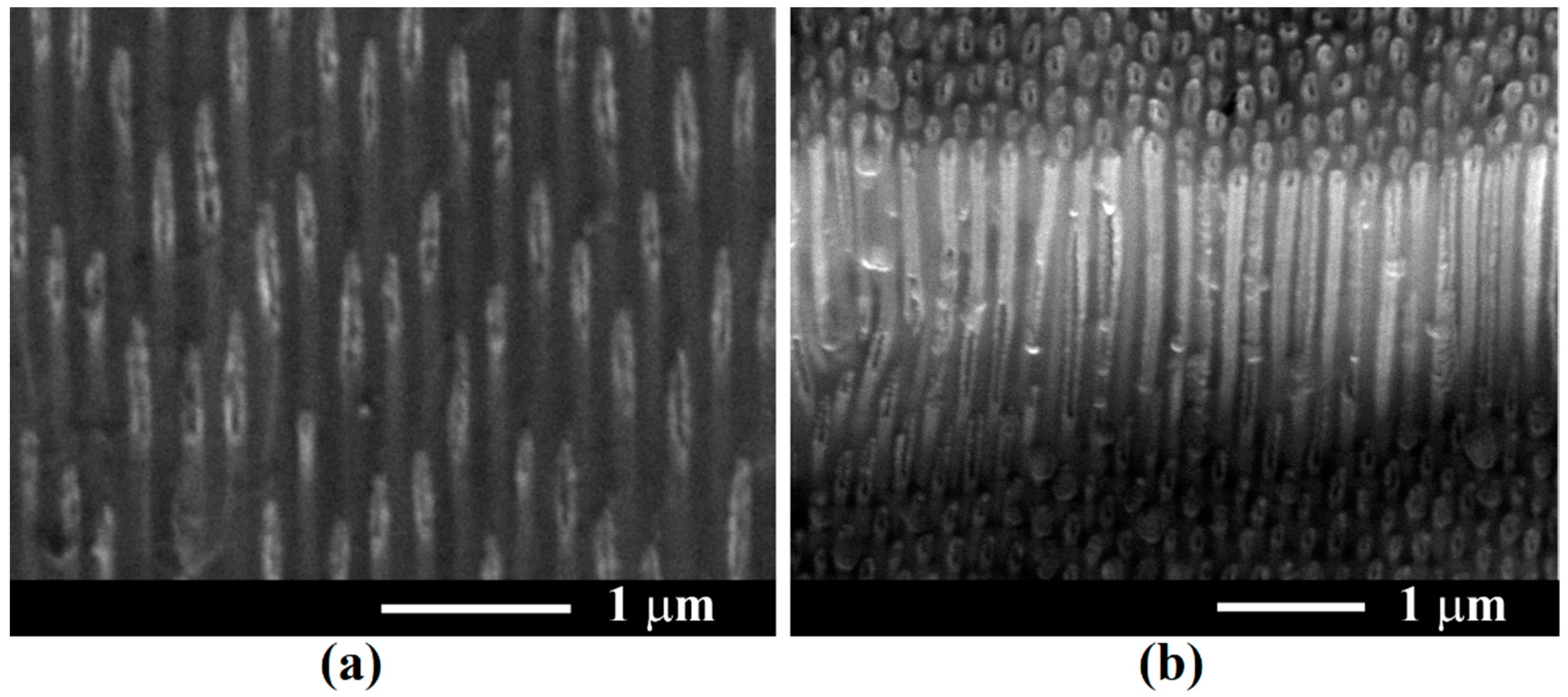
Another important parameter in pulsed electrochemical deposition designated for obtaining metal nanodots or nanotubes, is the total duration of electroplating (tdep). The so-called “hopping electrodeposition” mechanism of gold nanodots on porous semiconductor structures was proposed and demonstrated in a previous work [30]. It was demonstrated that after nucleation, each dot increases in size up to a critical transverse dimension of about 20 nm, followed by nucleation of another gold nanodot in the vicinity. The process continues until the entire surface exposed to the electrolyte is covered by a monolayer of self-assembled gold nanodots forming walls of metal nanotubes (Figure 4a). In a longer duration of electroplating, the walls of the metal nanotubes become thicker, as can be seen in Figure 4b. The optimum parameters of the pulses (Figure 3d) assure the uniform deposition along the nanotube’s depth.
The site-selective deposition of Pt in a porous GaP template was applied for the fabrication of a variable capacitance device with Schottky contact (Figure 5). Uniform Pt nanotubes were deposited in template pores at a depth of 70 µm as the first step of the electrodeposition process with optimized pulse parameters (toff = 1 s), according to Figure 3d, while the up contact of the device was formed at the second step of the electrodeposition process with pulse parameters leading to electrolyte depletion inside the pores (toff = 10 ms), according to Figure 3b.
The electrochemical deposition of the up contact in the same technological process is an advantage compared with evaporation techniques, since it assures the interconnection of all Pt nanotubes leading to better performance of the varicap device. A record gradient of capacity per square micrometer of the template-based variable capacitance device was reported [31,32].
Our estimations suggest that increasing the pore depth in the porous GaP template up to 300 µm would improve the device performance up to four to five times. Preliminary results indicate that increasing the pause between pulses to 3 s, and decreasing the pulse width from 300 µs to 100 µs under permanent magnetic steering, is required to reach this goal.
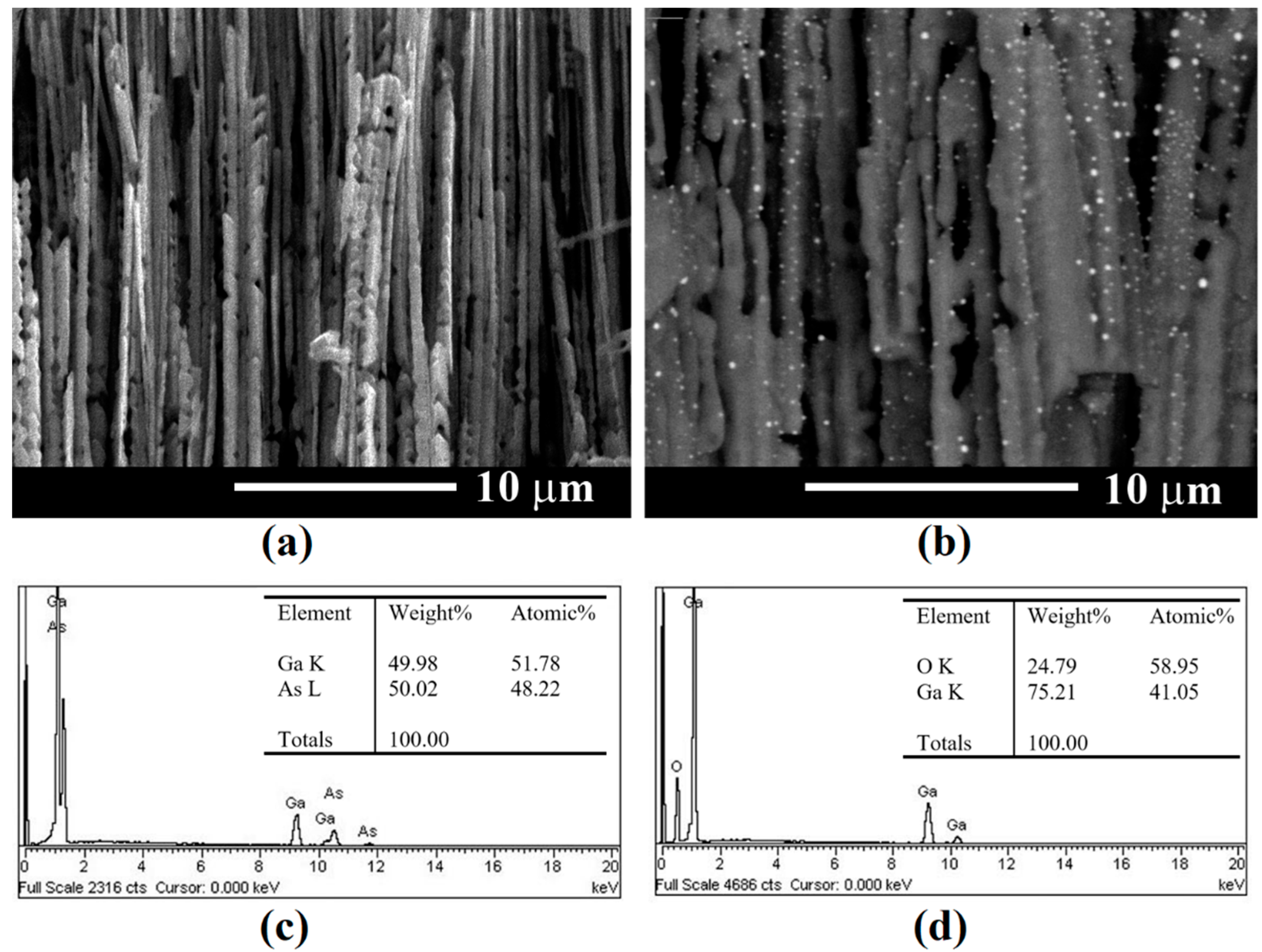
As mentioned in the introduction section, controlled electrodeposition in porous oxide templates is challenging because of its high electrical resistivity. One can propose an alternative approach for the preparation of noble metal deposition inside oxide templates based on a two-step process: metals are deposited in porous semiconductor templates in the first step, as discussed above for InP templates; then, after noble metal deposition, the semiconductor skeleton is oxidized. This approach was demonstrated in the instance of porous GaAs templates in the form of arrays of nanowires, as shown in Figure 6. Arrays of GaAs nanowires were produced by anodization of GaAs(111)B wafers in an 1M HNO3 electrolyte at 4 V for 20 min (Figure 6a). Au nanodots were deposited on the GaAs array by electroplating at pulse voltage value −16 V, ton = 100 µs, toff = 1 s, for 300 s (Figure 6b). Oxidation of GaAs wires after electroplating was performed by annealing at 800 °C for 1 h in air. Figure 6c,d shows the results of EDX analysis before and after oxidation, respectively.
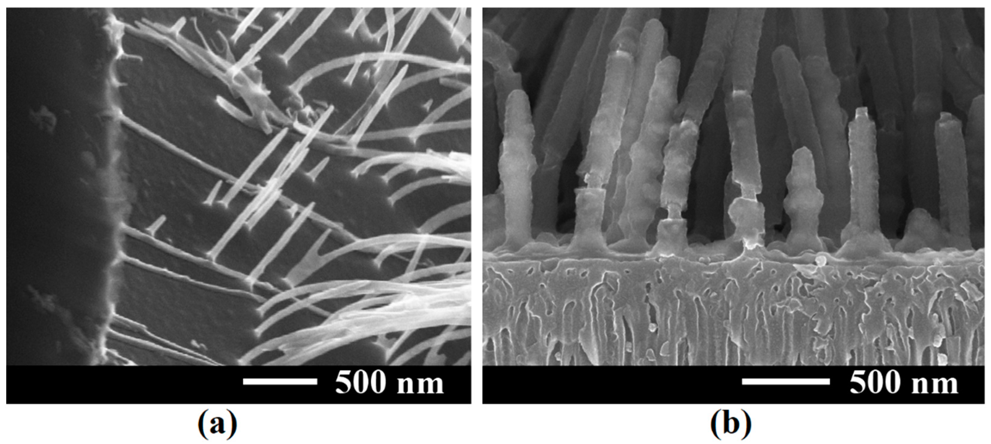
Figure 7 illustrates arrays of InP nanowires covered by Pt coatings. InP nanowires were produced by fast electrochemical etching [33] of InP substrates with an electron concentration of 1.3 × 1018 cm−3 in a 5% HCl electrolyte at an anodization voltage of 15 V for 3 s (Figure 7a). The approach of “fast electrochemical etching” was used, 2-µm long InP nanowires being obtained in just 3 s of anodization. Note that anodization at 5–6 V results in the formation of self-ordered porous InP structure, while ultrathin nanowalls, nanobelts or nanowires are produced at a relatively high applied potential, leading to the electrochemical dissolution of InP crystal around the remained nanostructures [33]. This approach, in combination with pulsed electrochemical deposition of gold nanodots, was used to assess the conductivity of the fabricated InP nanostructures depending on their thickness [29]. On the other hand, core–shell InP/Pt structures were fabricated by electroplating Pt on the prepared InP nanowires at a pulse voltage value −16 V, ton = 300 µs, toff = 0.5 s, for 1.5 h (Figure 7b). It should be noted that a uniform Pt deposition along the nanowires took place and interruptions occurred due to cross-sectioning of the sample.

4. Conclusions

The results of this study demonstrate possibilities for site-selective pulsed electrodeposition of metallic nanostructures in porous templates prepared by electrochemical etching of semiconductor wafers. Metal deposition occurred in the upper part of pores near the porous template surface under conditions of high amplitude, long current pulse width, and short interval between pulses, while the metal was deposited at the bottom of pores at conditions of low pulse amplitude and long intervals between pulses. Uniform deposition of the metal along the whole pore length was obtained with pulse parameters optimized from the point of view of effective electrolyte refreshing and avoiding its depletion in pores. This technology can be applied for the development of optoelectronic devices, particularly variable capacitance devices, as well as for plasmonic and photocatalytic applications. The technology can also be applied for the preparation of metal nanostructures on porous oxide templates, when it is combined with thermal treatment for the oxidation of the porous semiconductor skeleton.

Author Contributions

Conceptualization, E.V.M.; methodology, E.I.M., V.V.U., E.V.M.; validation, V.V.U. and E.V.M.; investigation, E.I.M. and E.V.M.; writing—original draft preparation, V.V.U. and E.V.M.; writing—review and editing, V.V.U., E.V.M. and I.M.T.; visualization, E.I.M. and E.V.M.; supervision, I.M.T.; project administration, E.V.M. and I.M.T.; funding acquisition, I.M.T. All authors have read and agreed to the published version of the manuscript.

Funding

This research was funded by National Agency for Research and Development of Moldova under grants #20.80009.5007.20 and #21.00208.5007.15/PD “Micro- and nano-engineering of semiconductor compounds based on electrochemical technologies for electronic and photonic applications”. The APC was funded by European Commission under the H2020 grant #810652 ‘NanoMedTwin’.

Institutional Review Board Statement

Not applicable.

Informed Consent Statement

Not applicable.

Data Availability Statement

The data presented in this study are available on request from the corresponding author.

Acknowledgments

E.V.M. acknowledges support from the Alexander von Humboldt Foundation (Bonn, Germany).

Conflicts of Interest

The authors declare no conflict of interest. The founding sponsors had no role in the design of the study; in the collection, analyses, or interpretation of data; in the writing of the manuscript, and in the decision to publish the results.

References

  1. Anik, M.I.; Hossain, M.K.; Hossain, I.; Mahfuz, A.M.U.B.; Rahman, M.T.; Ahmed, I. Recent Progress of Magnetic Nanoparticles in Biomedical Applications: A Review. Nano Sel. 2021, 2, 1146–1186. [Google Scholar] [CrossRef]
  2. Li, K.; Xu, J.; Li, P.; Fan, Y. A Review of Magnetic Ordered Materials in Biomedical Field: Constructions, Applications and Prospects. Compos. Part B Eng. 2022, 228, 109401. [Google Scholar] [CrossRef]
  3. Cardoso, V.F.; Francesko, A.; Ribeiro, C.; Bañobre-López, M.; Martins, P.; Lanceros-Mendez, S. Advances in Magnetic Nanoparticles for Biomedical Applications. Adv. Healthc. Mater. 2018, 7, 1700845. [Google Scholar] [CrossRef]
  4. Mohammed, H.; Moreno, J.A.; Kosel, J. Advanced Fabrication and Characterization of Magnetic Nanowires; IntechOpen: London, UK, 2017; ISBN 978-1-78923-679-8. [Google Scholar]
  5. Shah, K.W.; Xiong, T. Multifunctional Metallic Nanowires in Advanced Building Applications. Materials 2019, 12, 1731. [Google Scholar] [CrossRef] [PubMed] [Green Version]
  6. Proenca, M.P.; Sousa, C.T.; Ventura, J.; Araújo, J.P. 6—Cylindrical Magnetic Nanotubes: Synthesis, Magnetism and Applications. In Magnetic Nano- and Microwires, 2nd ed.; Vázquez, M., Ed.; Woodhead Publishing Series in Electronic and Optical Materials; Woodhead Publishing: Sawston, UK, 2020; pp. 135–184. ISBN 978-0-08-102832-2. [Google Scholar]
  7. Staňo, M.; Fruchart, O. Chapter 3—Magnetic Nanowires and Nanotubes. In Handbook of Magnetic Materials; Brück, E., Ed.; Elsevier: Amsterdam, The Netherlands, 2018; Volume 27, pp. 155–267. [Google Scholar]
  8. Sharma, M.; Kuanr, B.K. Electrodeposition of Ferromagnetic Nanostructures; IntechOpen: London, UK, 2015; ISBN 978-953-51-2213-5. [Google Scholar]
  9. Gerein, N.J.; Haber, J.A. Effect of AC Electrodeposition Conditions on the Growth of High Aspect Ratio Copper Nanowires in Porous Aluminum Oxide Templates. J. Phys. Chem. B 2005, 109, 17372–17385. [Google Scholar] [CrossRef] [PubMed]
  10. Yue, S.; Zhang, Y.; Du, J. Preparation of Anodic Aluminum Oxide Tubular Membranes with Various Geometries. Mater. Chem. Phys. 2011, 128, 187–190. [Google Scholar] [CrossRef]
  11. Enculescu, I. Nanowires and Nanotubes Prepared Using Ion Track Membrane Templates. Dig. J Nanomater. Biostructures 2006, 1, 15–20. [Google Scholar]
  12. Enculescu, I.; Siwy, Z.; Dobrev, D.; Trautmann, C.; Toimil Molares, M.E.; Neumann, R.; Hjort, K.; Westerberg, L.; Spohr, R. Copper Nanowires Electrodeposited in Etched Single-Ion Track Templates. Appl. Phys. A 2003, 77, 751–755. [Google Scholar] [CrossRef]
  13. Martin, C.R. Nanomaterials: A Membrane-Based Synthetic Approach. Science 1994, 266, 1961–1966. [Google Scholar] [CrossRef]
  14. Sulka, G.; Zaraska, L.; Stępniowski, W. Anodic Porous Alumina as a Template for Nanofabrication. In Encyclopedia of Nanoscience and Nanotechnology; American Scientific Publishers: Valencia, CA, USA, 2011; Volume 11, pp. 261–349. [Google Scholar]
  15. Tiginyanu, I.; Ursaki, V.; Monaico, E. Template Assisted Formation of Metal Nanotubes. In Nanostructures and Thin Films for Multifunctional Applications: Technology, Properties and Devices; Tiginyanu, I., Topala, P., Ursaki, V., Eds.; NanoScience and Technology; Springer International Publishing: Cham, Switzerland, 2016; pp. 473–506. ISBN 978-3-319-30198-3. [Google Scholar]
  16. Langa, S.; Carstensen, J.; Tiginyanu, I.M.; Christophersen, M.; Föll, H. Formation of Tetrahedron-Like Pores during Anodic Etching of (100) Oriented n-GaAs. Electrochem. Solid-State Lett. 2001, 5, C14. [Google Scholar] [CrossRef]
  17. Monaico, E.; Tiginyanu, I.; Ursaki, V. Porous Semiconductor Compounds. Semicond. Sci. Technol. 2020, 35, 103001. [Google Scholar] [CrossRef]
  18. Tiginyanu, I.M.; Ursaki, V.V.; Monaico, E.; Enachi, M.; Sergentu, V.V.; Colibaba, G.; Nedeoglo, D.D.; Cojocaru, A.; Föll, H. Quasi-Ordered Networks of Metal Nanotubes Embedded in Semiconductor Matrices for Photonic Applications. J. Nanoelectron. Optoelectron. 2011, 6, 463–472. [Google Scholar] [CrossRef]
  19. Belov, A.N.; Gavrilov, S.A.; Shevyakov, V.I.; Redichev, E.N. Pulsed Electrodeposition of Metals into Porous Anodic Alumina. Appl. Phys. A 2011, 102, 219–223. [Google Scholar] [CrossRef]
  20. Abbondanza, G.; Larsson, A.; Linpé, W.; Hetherington, C.; Carlá, F.; Lundgren, E.; Harlow, G.S. Templated Electrodeposition as a Scalable and Surfactant-Free Approach to the Synthesis of Au Nanoparticles with Tunable Aspect Ratios. Nanoscale Adv. 2022, 4, 2452–2467. [Google Scholar] [CrossRef] [PubMed]
  21. Tiginyanu, I.; Monaico, E.; Monaico, E. Ordered Arrays of Metal Nanotubes in Semiconductor Envelope. Electrochem. Commun. 2008, 10, 731–734. [Google Scholar] [CrossRef]
  22. Dela Pena, E.M.; Roy, S. Electrodeposited Copper Using Direct and Pulse Currents from Electrolytes Containing Low Concentration of Additives. Surf. Coat. Technol. 2018, 339, 101–110. [Google Scholar] [CrossRef] [Green Version]
  23. Boukhouiete, A.; Creus, J. Nickel Deposits Obtained by Continuous and Pulsed Electrodeposition Processes. J. Mater. Environ. Sci. 2015, 6, 1840–1844. [Google Scholar]
  24. Renner, F.U.; Ankah, G.N.; Bashir, A.; Ma, D.; Biedermann, P.U.; Shrestha, B.R.; Nellessen, M.; Khorashadizadeh, A.; Losada-Pérez, P.; Duarte, M.J.; et al. Star-Shaped Crystallographic Cracking of Localized Nanoporous Defects. Adv. Mater. 2015, 27, 4877–4882. [Google Scholar] [CrossRef]
  25. Plesco, I.; Ciobanu, V.; Braniste, T.; Ursaki, V.; Rasch, F.; Sarua, A.; Raevschi, S.; Adelung, R.; Dutta, J.; Tiginyanu, I. Highly Porous and Ultra-Lightweight Aero-Ga2O3: Enhancement of Photocatalytic Activity by Noble Metals. Materials 2021, 14, 1985. [Google Scholar] [CrossRef]
  26. Enachi, M.; Guix, M.; Postolache, V.; Ciobanu, V.; Fomin, V.M.; Schmidt, O.G.; Tiginyanu, I. Light-Induced Motion of Microengines Based on Microarrays of TiO2 Nanotubes. Small 2016, 12, 5497–5505. [Google Scholar] [CrossRef]
  27. Monaico, E.; Tiginyanu, I.M.; Ursaki, V.V.; Sarua, A.; Kuball, M.; Nedeoglo, D.D.; Sirkeli, V.P. Photoluminescence and Vibrational Properties of Nanostructured ZnSe Templates. Semicond. Sci. Technol. 2007, 22, 1115–1121. [Google Scholar] [CrossRef]
  28. Irmer, G.; Monaico, E.; Tiginyanu, I.M.; Gärtner, G.; Ursaki, V.V.; Kolibaba, G.V.; Nedeoglo, D.D. Fröhlich Vibrational Modes in Porous ZnSe Studied by Raman Scattering and Fourier Transform Infrared Reflectance. J. Phys. Appl. Phys. 2009, 42, 045405. [Google Scholar] [CrossRef]
  29. Monaico, E.V.; Tiginyanu, I.M.; Ursaki, V.V.; Nielsch, K.; Balan, D.; Prodana, M.; Enachescu, M. Gold Electroplating as a Tool for Assessing the Conductivity of InP Nanostructures Fabricated by Anodic Etching of Crystalline Substrates. J. Electrochem. Soc. 2017, 164, D179. [Google Scholar] [CrossRef]
  30. Tiginyanu, I.; Monaico, E.; Nielsch, K. Self-Assembled Monolayer of Au Nanodots Deposited on Porous Semiconductor Structures. ECS Electrochem. Lett. 2015, 4, D8. [Google Scholar] [CrossRef]
  31. Tiginyanu, I.; Monaico, E.; Ursaki, V. Two-Dimensional Metallo-Semiconductor Networks for Electronic and Photonic Applications. ECS Trans. 2012, 41, 67. [Google Scholar] [CrossRef]
  32. Tiginyanu, I.; Monaico, E.; Sergentu, V.; Tiron, A.; Ursaki, V. Metallized Porous GaP Templates for Electronic and Photonic Applications. ECS J. Solid State Sci. Technol. 2015, 4, P57. [Google Scholar] [CrossRef]
  33. Monaico, E.; Tiginyanu, I.; Volciuc, O.; Mehrtens, T.; Rosenauer, A.; Gutowski, J.; Nielsch, K. Formation of InP Nanomembranes and Nanowires under Fast Anodic Etching of Bulk Substrates. Electrochem. Commun. 2014, 47, 29–32. [Google Scholar] [CrossRef]
Figure 1. Schematic representation of the set-up for electrochemical etching of semiconductor substrates as well as pulsed electrochemical deposition of metal nanostructures in porous semiconductor templates. The technological work-flow is presented for InP crystals.
Coatings 12 01521 g001
Figure 2. (a) Schematic representation of self-ordered porous layer formation; (b) cross-sectional SEM image of deposited segmented Pt nanotubes in porous InP template with a top nucleation layer (U = −16 V; ton = 100 µs; toff = 1 s); (c) top view SEM images after removal of the top nucleation layer by wet chemical etching in HCl:H3PO4 (1:1) during 10 s; (d) the same for etching during 25 s.
Coatings 12 01521 g002
Figure 3. Site-selective pulsed electroplating of metal species in porous InP semiconductor nanotemplates at different deposition parameters: (a) continuously applied voltage leading to deposition on top of the template (toff = 0); (b) deposition on and underneath surface at small delay applied between the pulses (toff); (c) selective deposition of metal at the bottom of pores by applying a small voltage pulse amplitude; and (d) uniform deposition along the whole template thickness at optimized pulse width, delay between pulses and voltage amplitude resulting in the formation of Pt nanotubes. In row (I), a schematic representation of applied pulses is presented. In row (II), a schematic art-view of the metal species penetration inside pores, depending on the pulse parameters is presented; the blue lines illustrate the current lines. In row (III), a schematic representation of the deposited metal in porous InP template is presented, and row (IV) demonstrates the site-selective deposition by SEM images in cross-sectional view.
Coatings 12 01521 g003
Figure 4. SEM images in cross-section, of Pt nanotubes in semiconductor InP envelope after electrochemical deposition with electroplating parameters of U = −16 V, ton = 100 µs, toff = 1 s, at different durations of electroplating: (a) 1 h; and (b) 2.5 h.
Coatings 12 01521 g004
Figure 5. (a) SEM image in cross-section, of 100 µm deep porous GaP/Pt template; (b) the schematic presentation of the varicap device structure; (c) the sequence of pulses and pause between them during Pt electroplating in porous GaP template for Pt nanotubes and top contact deposition in the same technological process.
Coatings 12 01521 g005
Figure 6. (a) GaAs nanowires after anodization of GaAs(111)B crystal in 1M HNO3 at 4 V for 20 min; (b) Ga2O3/Au nanowires obtained by annealing at 800 °C for 1 h of GaAs nanowires with deposited gold nanodots; (c) the results of chemical composition analysis of GaAs nanowires after anodization; (d) the same after thermal annealing.
Coatings 12 01521 g006
Figure 7. SEM cross-sectional image of: (a) InP nanowires obtained via fast electrochemical etching of InP substrates at 15 V for 3 s; (b) core–shell InP/Pt structure on porous InP.
Coatings 12 01521 g007
Publisher’s Note: MDPI stays neutral with regard to jurisdictional claims in published maps and institutional affiliations.