Article

Effects of Sintering Temperature on MoOx Target and Film

1
Shenzhen APG Material Technology Co., Ltd. (APG), Shenzhen 518000, China
2
Department of Mechanical and Electronic Engineering, Changsha University, Changsha 410022, China
3
School of Materials Science and Engineering, Guilin University of Electronic Technology, Guilin 541004, China
*
Author to whom correspondence should be addressed.
Coatings 2022, 12(11), 1624; https://doi.org/10.3390/coatings12111624
Submission received: 29 September 2022 / Revised: 21 October 2022 / Accepted: 22 October 2022 / Published: 26 October 2022
(This article belongs to the Topic Properties of the Corroding Interface)

Abstract

:
The sintering process of the MoOx target has an impact on the quality of the sputtered film. In this study, powders of MoO3 (78 wt%) and MoO2 (22 wt%) were milled and hot-pressed to prepare the MoOx target. The effects of the sintering temperature of the MoOx targets on the properties of the sputtered MoOx films were investigated by X-ray diffraction, scanning electron microscopy, four-probe needle, and spectrophotometer tests. The research results revealed that the MoOx target at the sintered temperature of 1000 °C had a clear crystal structure and dense grains, exhibiting good sinterability, crystallization behavior, and film-forming property. The sputtered film deposited by the MoOx target could obtain high quality with a smooth interface and uniform thickness. The film had smaller resistivity, higher reflectivity, and appropriate transmissivity compared to the ones fabricated by other targets that were sintered at 800 °C, 900 °C, and 1100 °C.

1. Introduction

Molybdenum trioxide (MoOx), with high transparency, nontoxicity, and moderate evaporation temperature, has potential application value in the field of optoelectronic devices [1,2]. Because of a broad work function of about 6.7 eV, MoOx can be used as the hole extraction layer in photovoltaic devices, light-emitting devices, and sensors due to photochromism, electrochromism, and low reflectance [3,4,5]. For these devices involving the MoOx hole extraction layers, their capabilities mostly rely on the MoOx thin films [6]. MoOx is a compound-oxide semiconductor with an indirect band gap and is also considered to be a promising candidate in potential applications of hole injection layer between Transparent Conducting Oxide (TCO) and Organic Light-Emitting Diode (OLED) [7]. In the photovoltaic field, MoOx as the cathode buffer layer can effectively improve electrode contact, lower the Schottky barrier, and then improve the photovoltaic performance of solar cells [8]. For the narrow bezel in a thin-film transistor (TFT) backplane, MoOx is also a cost-efficient and reliable thin-film material [9]. In the new touch panel device, MoOx can be employed as a functional film to reduce the reflection of a metal-mesh electrode and to improve the effect of shadow elimination [10]. In addition, MoOx shows many advantages, including low cost, lightweight, and flexibility.
Molybdenum is normally oxidized with stable oxidation states of +4, +5, and +6. The Mo-O system is complex, displaying two stable oxide phases: MoO2, which is dark and opaque and is electrically conductive, and MoO3, which has a yellowish transparent appearance but is insulating [11]. Furthermore, there are numerous line phases between MoO2 and MoO3, which are brownish to greyish and are semiconducting. This complexity may be one reason for the difficulty in extracting the optical constants [12]. Magnéli [13] reported the existence of oxygen-deficient oxides (MonO3n−1 or MonO3n−2). At present, the tri-oxide MoO3 film is considered the most prominent one [14]. However, MoO3 displays a poor photocatalytic property because of the wide band gap and high recombination of photo-generated electron-hole pairs [15]. Guo et al. [16] indicated that when x was smaller than 3, MoOx had a broader work function due to the closed shell character in the electronic structure and the dipoles created by its internal layer structure. Domínguez et al. [17] reported the good optoelectronic properties of thin MoOx films with 2 < x < 3. Therefore, reducing the oxygen content of MoO3 aims to optimize the band gap and the lifetime of electron-hole pairs [18].
MoOx film can be fabricated by reactive sputtering, pulsed laser deposition, thermal evaporation, and spin coating using molybdenum targets [19]. The process is prepared by feeding oxygen, oxygen can often improve the effectiveness of magnetron sputtering, but it is very hard to control the oxygen [20]. Lin et al. [21] used MoO3 ceramic targets with a 6% O2/Ar flow rate to prepare MoOx films with high transparency and an optical band gap. Hong et al. [22] manufactured MoOx nanoparticle films through laser ablation from molybdenum targets at ambient conditions. Gretener et al. [23] prepared thin MoOx films by reactive sputtering in a mixed oxygen-argon atmosphere with a metallic Mo target or a ceramic MoO3 target. David et al. [24] deposited antireflection coatings to hide metal architecture by sputtering MoOx thin films. Pachlhofer et al. [11] synthesized Mo-O thin films using ceramic MoOx targets with compositions ranging from x = 2.5 to 2.8. To investigate the reflectance of light from external sources and the resulting color impression of the dark layer coatings, Hennrik [25] used ceramic oxide targets to deposit a thin layer of metal oxide.
In this research, MoOx ceramic target materials were prepared at different sintering temperatures through a hot-pressing sintering process, and then magnetron sputtering coating was carried out to examine the effects of different sintering temperatures on the crystal shape, microstructure, and density of MoOx ceramics, and to further compare the structure and photoelectrical properties of MoOx films. It was expected that the MoOx ceramic film as a sputtering source could be used to prepare MoOx film for the new touch panel and narrow frame LCD device based on a metal-mesh electrode.

2. Experimental Methods

Powders of MoO3 (78 wt%) and MoO2 (22 wt%) were ball-milled with the absolute ethanol solvent for 4 h. They were sifted and dried to obtain 50 mesh powders. The MoOx targets were prepared by hot-pressed sintering at temperatures of 800 °C, 900 °C, 1000 °C, and 1100 °C. When the sintering temperature reached the set values for 3 h, the exerting pressure was initiated. After 1.5 h, the pressure value was increased to 100 tons, and the pressure remained unchanged for 1 h. Then, the pressure and the temperature were released to the normal temperature and pressure. The hot-pressing sintered targets were achieved. Finally, the MoOx thin films were subjected to direct current (DC) sputtering in the Ar atmosphere at the power density of 2.14 W/cm2 for 48 s, sodium–calcium glass was used as the substrate, and the thickness of the sputtered films was set to 45 nm. The phases of the sintered targets were identified with a DMAX-2500X x-ray diffractometry (XRD, D/MAX 2500, Rigaku, Tokyo, Japan). The morphologies of sintered targets and deposited films were observed by SEM (MIRA4 LMH, TESCAN, Brno, Czech Republic) using secondary electron imaging. The four-probe needle tester was utilized to measure the resistivity (ρ) of thin films, and the light transmissivity and reflectance were tested by CM-700d spectrophotometer (Konica Minolta, Tokyo, Japan).

3. Results and Discussion

Figure 1 shows the XRD patterns of the MoOx targets at different sintered temperatures. It can be observed in the samples that the existing diffraction peaks are related to the Mo4O11, MoO2, Mo18O52, and MoO3 phases. In the initial stage of sintering, the target was composed of MoO3 and MoO2 powders. During the sintering, the environmental atmosphere and elevated temperature resulted in non-stoichiometric and more complex structures in MoOx targets. According to the Mo-O system calculated by Zhang et al. [26], it generates a more complex series of thermal reactions above 800 °C (Equations (1)–(4)).
L(liquid phase) + MoO2 → Mo4O11
L(liquid phase) + Mo4O11 → Mo8O23
L(liquid phase) + Mo8O23 → Mo18O52
L(liquid phase) + Mo18O52 → MoO3
Four types of phases can be observed in MoOx targets at different sintering temperatures, but the volume fraction of phases has a significant difference due to the intensity of diffraction peaks. Moreover, the main component is the Mo4O11 phase in the sample sintered at 800 °C (Figure 1). However, the volume fraction of the Mo4O11 phase gradually decreases with an increase in the sintered temperature. When the sintered temperature increased to 900 °C, the peak intensity of MoO2 increased (Figure 1b). At 1000 °C, it showed a marked variation for the Mo18O52 phase (Figure 1c), while the peak intensity of the MoO2 exhibited no obvious change. When the sintering temperature of the MoOx target reached 1100 °C, the diffraction peaks of the MoO2 phase constituted the main status (Figure 1d).
Figure 2 depicts the SEM images of the MoOx targets at different sintering temperatures, and it reveals the sintering process and grain size variation. When the sintering temperature was 800 °C, a flocculent structure was formed with crystals and loose powders (Figure 2a). The number of crystals increased at 900 °C, while that of loose powders decreased (Figure 2b), implying a typical sintering process [27]. The bonding between powders mainly depends on the sintering temperature and diffusion rate [28]. The diffusion phenomenon can be explained using the following equation [29]:
D = D o e x p ( Q R T )
where D is the diffusion coefficient, DO is set as a constant determined by the physicochemical property of the elements, and Q, R, and T represent the activation energy, Boltzmann’s constant, and thermodynamic temperature, respectively. Obviously, a high sintering temperature can facilitate the diffusion of the elements, creating more coalesced opportunities for powders. A dense sintered structure is dependent on a high diffusion rate; thus, the sintering temperature is recognized as the main controlling factor during the sintering process [30]. Figure 2c,d suggest that the samples sintered at 1000 °C and 1100 °C displayed a clear crystal structure. Thus, the sinterability and crystallization behavior of the MoOx targets were improved with the increase in the sintering temperature. In addition, the density of the MoOx targets was 4.3 g/cm3, 4.6 g/cm3, 5.6 g/cm3, and 5.1 g/cm3, respectively. This also demonstrated various sintering effects at different temperatures.
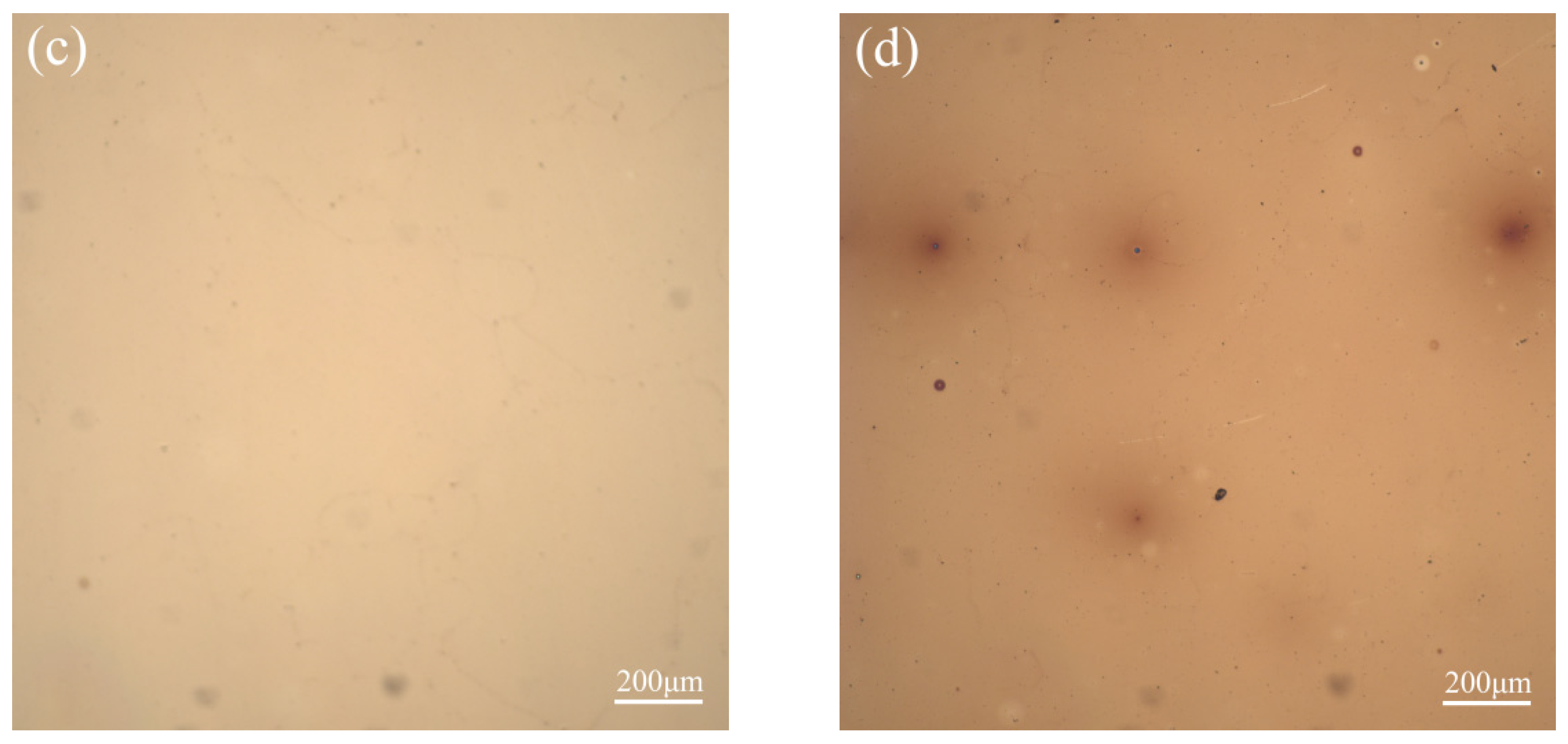
Figure 3 depicts digital photos of the sputtered films using different MoOx targets. According to the quality of the films, it was easy to predict the film-forming property with different MoOx targets. When the sintering temperature of the MoOx target was 800 °C, some spots were observed on the sputtered film (Figure 3a,b,d), presenting a ripple effect with dark specks. When the MoOx target sintered at 1000 °C was used, a smooth and regular surface was formed (Figure 3c). Figure 4 shows a cross-section view of the sputtered films. MoOx is a black transparent film, which is similar to a glass base, and the interface can be observed from the SEM test pictures. When the sputtering utilized an 800°C—sintered MoOx target, the interface was very obvious, the surface morphology was rough, and the thickness of the sputtered film was 415.71 nm, which was bigger than 45 nm (Figure 4a). Although the MoOx thin film, which was prepared by the target sintered at 900 °C, displayed a smooth interface (Figure 4b), a continuous layer structure was observed on the interface, and its maximum thickness was up to 520.08 nm. The sputtered film using the 1000 °C—sintered MoOx target exhibited a uniform interface, and the thickness of the film was 44.68 nm (Figure 4c), which was very close to the set value (45 nm). Figure 4d presents a similar interface compared to Figure 4c, while a narrow peak structure is developed, which results in an asymmetric film. Thus, the 1000-°C-sintered target showed a better film-forming property compared with that of other ones. Generally, the thickness of the sputtered film is related to the distance between the target and the substrate, sputtering power, and working pressure. In this study, the technological parameters were set. By comparing the thickness uniformity of the sputtered films, the film-forming property was evaluated. Normally, the film-forming property has a close relationship with the density, grain size, and composition of the targets [4,5,22]. Thus, the inhomogeneities of MoOx led to the confusion of electromagnetic fields and the uneven distribution of plasma density. Ultimately, it resulted in the non-uniform deposition of the target atoms during the uneven sputtering process. Given the microstructure of the MoOx targets, it can be found that the MoOx target sintered at 1000 °C has a clear crystal structure with uniform grain size, indicating a good film-forming property. For the 900-°C-sintered MoOx target, the poor film-forming property was attributed to the loose structure and incomplete crystallization. The irregular film formed by the targets, which was sintered at 1100 °C, was due to the heterogeneous grain structure.
Figure 5 displays the variation trend in the resistivity, reflectivity, and transmissivity of the sputtered films with the sintering temperature of MoOx targets. It was observed that the resistivity of the sputtered films was raised initially, then decreased with the increasing sintering temperature. The resistivity reflects the electrical properties of the material, which is dependent on the quality of the sputtered films [11,12]. According to Figure 3 and Figure 4, the sputtered film formed by the 800 °C—sintered MoOx target has a rough and thick interface, which caused a high resistivity value. For the film prepared by the 900 °C—sintered MoOx target, the continuous layer structure also increased the resistivity value. However, the sputtered film using the 1000 °C—sintered MoOx target had a smaller resistivity value compared to other ones because of the smooth interface and uniform thickness. Furthermore, MoO3 presented an insulating property, and MoO2 had a better electric conductivity [11]. Thus, the sputtered film deposited by the 1100-°C-sintered MoOx target represented a smaller resistivity value compared with the ones sintered at 800 °C and 900 °C, though the narrow peak structure formed on the film. It is worth noting that the reflectivity and transmissivity of the sputtered films initially increased and then decreased with the increasing sintering temperature. It is clear that both the reflectivity and the transmissivity are controlled by the thickness and morphology of the sputtered films [17,24]. Therefore, the film, which was prepared by the targets and was sintered at 800 °C and 900 °C, presented low reflectivity and transmissivity because of its inhomogeneous structure and thick film layer. Moreover, the narrow peak structure had a great influence on the reflectivity and transmissivity of the sputtered film deposited by the 1100 °C—sintered MoOx target.

4. Conclusions

The MoOx target exhibited good sinterability and crystallization behavior at 1000 °C and had a clear crystal structure, dense grains, and higher density. The MoOx target sintered at 1000 °C has a good film-forming property, which formed a smooth interface with uniform thickness, and the thickness was much closer to the set value of 45 nm. The sputtered film using the 1000 °C—sintered MoOx target had a smaller resistivity and higher reflectivity and transmittance value compared with other targets sintered at 800 °C, 900 °C, and 1100 °C. In addition, the sintered MoOx target at 1000 °C was more suitable for preparing the MoOx film of the new touch panel and the narrow frame LCD device.

Author Contributions

Conceptualization, X.Z.; Data curation, X.Z.; Formal analysis, H.X.; Writing—original draft, X.Z.; Writing—review & editing, J.X. All authors have read and agreed to the published version of the manuscript.

Funding

This research was funded by High-tech Industry Technology Innovation Leading Plan of Hunan Province (Grant No.: 2020GK2032), Natural Science Foundation of Hunan Province China (Grant No. 2022JJ50010).

Institutional Review Board Statement

Not applicable.

Informed Consent Statement

Not applicable.

Data Availability Statement

Data will be made available on request.

Conflicts of Interest

The authors declare no conflict of interest.

References

  1. Bullock, J.; Hettick, M.; Geissbühler, J.; Ong, A.J.; Allen, T.; Sutter-Fella, C.M.; Chen, T.; Ota, H.; Schaler, E.W.; De Wolf, S.; et al. Efficient silicon solar cells with dopant-free asymmetric heterocontacts. Nat. Energy 2016, 1, 15031. [Google Scholar] [CrossRef]
  2. Gerling, L.G.; Mahato, S.; Morales-Vilches, A.; Masmitja, G.; Ortega, P.; Voz, C.; Alcubilla, R.; Puigdollers, J. Transition metal oxides as hole-selective contacts in silicon heterojunctions solar cells. Sol. Energy Mater. Sol. Cells 2016, 145, 109–115. [Google Scholar] [CrossRef] [Green Version]
  3. Bessonov, A.A.; Kirikova, M.N.; Petukhov, D.; Allen, M.; Ryhänen, T.; Bailey, M.J.A. Layered memristive and memcapacitive switches for printable electronics. Nat. Mater. 2015, 14, 199–204. [Google Scholar] [CrossRef] [PubMed]
  4. Cauduro, A.L.; Dos Reis, R.; Chen, G.; Schmid, A.K.; Methivier, C.; Rubahn, H.-G.; Bossard-Giannesini, L.; Cruguel, H.; Witkowski, N.; Madsen, M. Crystalline molybdenum oxide thin-films for application as interfacial layers in optoelectronic devices. ACS Appl. Mater. Interfaces 2017, 9, 7717–7724. [Google Scholar] [CrossRef] [Green Version]
  5. Bin, X.; Tian, Y.; Luo, Y.; Sheng, M.; Luo, Y.; Ju, M.; Que, W. High-performance flexible and free-standing N-doped Ti3C2Tx/MoOx films as electrodes for supercapacitors. Electrochim. Acta 2021, 389, 138774. [Google Scholar] [CrossRef]
  6. Jiang, Y.; Cao, S.; Lu, L.; Du, G.; Lin, Y.; Wang, J.; Yang, L.; Zhu, W.; Li, D. Post-annealing Effect on Optical and Electronic Properties of Thermally Evaporated MoOX Thin Films as Hole-Selective Contacts for p-Si Solar Cells. Nanoscale Res. Lett. 2021, 16, 1–11. [Google Scholar] [CrossRef]
  7. Wang, Z.; Zhang, C.; Chen, D.; Tang, S.; Zhang, J.; Wang, Y.; Han, G.; Xu, S.; Hao, Y. Flexible ITO-Free Organic Solar Cells Based on MoO3/Ag Anodes. IEEE Photonics J. 2015, 7, 1–9. [Google Scholar] [CrossRef]
  8. Vasilopoulou, M.; Douvas, A.M.; Georgiadou, D.G.; Palilis, L.C.; Kennou, S.; Sygellou, L.; Soultati, A.; Kostis, I.; Papadimitropoulos, G.; Davazoglou, D.; et al. The Influence of Hydrogenation and Oxygen Vacancies on Molybdenum Oxides Work Function and Gap States for Application in Organic Optoelectronics. J. Am. Chem. Soc. 2012, 134, 16178–16187. [Google Scholar] [CrossRef]
  9. Wang, S.; Guo, H.; Song, Y.; Ma, G.; Li, S.; Zhang, L.; Shao, X. P-63: Lower Reflective TFT Materials and Technology Innovation. SID Symp. Dig. Tech. Pap. 2017, 48, 1478–1481. [Google Scholar] [CrossRef]
  10. Shiming, W.; Xianghui, Z.; Zheli, Z.; Haiyu, G.; Xiaolai, S.; Baohui, L. Electrode Structure, Touch Pad and Touch Device. CN201721924180.8 25 September 2008. [Google Scholar]
  11. Pachlhofer, J.M.; Martín-Luengo, A.T.; Franz, R.; Franzke, E.; Köstenbauer, H.; Winkler, J.; Bonanni, A.; Mitterer, C. Non-reactive dc magnetron sputter deposition of Mo-O thin films from ceramic MoOx targets. Surf. Coat. Technol. 2017, 332, 80–85. [Google Scholar] [CrossRef]
  12. Pachlhofer, J.M.; Martín-Luengo, A.T.; Franz, R.; Franzke, E.; Köstenbauer, H.; Winkler, J.; Bonanni, A.; Mitterer, C. Industrial-scale sputter deposition of molybdenum oxide thin films: Microstructure evolution and properties. J. Vac. Sci. Technol. A Vac. Surf. Film. 2017, 35, 021504. [Google Scholar] [CrossRef]
  13. Magnéli, A. Structures of the ReO3-type with recurrent dislocations of atoms: ‘homologous series’ of molybdenum and tungsten oxides. Acta Crystallogr. 1953, 6, 495–500. [Google Scholar] [CrossRef] [Green Version]
  14. Zhao, N.; Fan, H.; Zhang, M.; Ma, J.; Du, Z.; Yan, B.; Li, H.; Jiang, X. Simple electrodeposition of MoO3 film on carbon cloth for high-performance aqueous symmetric supercapacitors. Chem. Eng. J. 2020, 390, 124477. [Google Scholar] [CrossRef]
  15. Alex, K.V.; Prabhakaran, A.; Jayakrishnan, A.R.; Kamakshi, K.; Silva, J.P.B.; Sekhar, K.C. Charge coupling enhanced photocatalytic activity of BaTiO3/MoO3 heterostructures. ACS Appl. Mater. Interfaces 2019, 11, 40114–40124. [Google Scholar] [CrossRef] [PubMed]
  16. Guo, Y.; Robertson, J. Origin of the high work function and high conductivity of MoO3. Appl. Phys. Lett. 2014, 105, 222110. [Google Scholar] [CrossRef] [Green Version]
  17. Dominguez, A.; De Melo, O.; Dutt, A.; Santana, G. Study of optoelectronic properties of thin MoOx films for application in silicon solar cells. In Proceedings of the 2019 IEEE 46th Photovoltaic Specialists Conference (PVSC), Chicago, IL, USA, 16–21 June 2019; pp. 2655–2658. [Google Scholar]
  18. Liu, X.; Bhatia, S.R. Laponite® and Laponite®-PEO hydrogels with enhanced elasticity in phosphate-buffered saline. Polym. Adv. Technol. 2015, 26, 874–879. [Google Scholar] [CrossRef]
  19. Fernandes Cauduro, A.L.; Fabrim, Z.E.; Ahmadpour, M.; Fichtner, P.F.P.; Hassing, S.; Rubahn, H.-G.; Madsen, M. Tuning the optoelectronic properties of amorphous MoOx films by reactive sputtering. Appl. Phys. Lett. 2015, 106, 202101. [Google Scholar] [CrossRef] [Green Version]
  20. Meng, B.; Wang, J.; Yang, L.; Chen, M.; Zhu, S.; Wang, F. On the rumpling mechanism in nanocrystalline coatings: Improved by reactive magnetron sputtering with oxygen. J. Mater. Sci. Technol. 2022, 132, 69–80. [Google Scholar] [CrossRef]
  21. Lin, T.; Chen, P.; Wang, Z.; Zhuang, K.; Chiu, S.; Peng, C.-H.; Lee, S.-W. Tailoring transparence in MoOx/Ag/MoOx electrode through Ag by O2/Ar plasma exposure. Ceram. Int. 2017, 43, 308–315. [Google Scholar] [CrossRef]
  22. Hong, R.; Li, Z.; Liu, Q.; Sun, W.; Deng, C.; Wang, Q.; Lin, H.; Tao, C.; Zhang, D. Fabrication and photocatalytic property of MoOx nano-particle films from Mo target by laser ablation at ambient conditions. Opt. Mater. 2020, 99, 109589. [Google Scholar] [CrossRef]
  23. Gretener, C.; Perrenoud, J.; Kranz, L.; Baechler, C.; Yoon, S.; Romanyuk, Y.; Buecheler, S.; Tiwari, A. Development of MoOx thin films as back contact buffer for CdTe solar cells in substrate configuration. Thin Solid Film. 2013, 535, 193–197. [Google Scholar] [CrossRef]
  24. Tsu, D.V.; Muehle, M.; Köstenbauer, H.; Linke, C.; Winkler, J. Optical properties of Mo and amorphous MoOx, and application to antireflection coatings for metals. J. Vac. Sci. Technol. B Nanotechnol. Microelectron. Mater. Process. Meas. Phenom. 2022, 40, 22209. [Google Scholar] [CrossRef]
  25. Schmidt, H.; Köstenbauer, H.; Köstenbauer, J.; Linke, C.; Franzke, E.; Winkler, J. Sputtered Molybdenum-Oxide for Anti-Reflection Layers in Displays: Optical Properties and Thermal Stability. SID Symp. Dig. Tech. Pap. 2018, 49, 225–229. [Google Scholar] [CrossRef]
  26. Zhang, C.; Gao, M.; Yang, Y.; Zhang, F. Thermodynamic modeling and first-principles calculations of the Mo–O system. Calphad 2014, 45, 178–187. [Google Scholar] [CrossRef]
  27. Huang, L.; Pan, Y.; Zhang, J.; Du, Y.; Zhang, Y. Remanufacturing of the waste refractory Mo–10Nb sputtering target by spark plasma sintering technology. Vacuum 2022, 200, 111050. [Google Scholar] [CrossRef]
  28. Min, K.H.; Kang, S.P.; Kim, D.-G.; Kim, Y.D. Sintering characteristic of Al2O3-reinforced 2xxx series Al composite powders. J. Alloy. Compd. 2005, 400, 150–153. [Google Scholar] [CrossRef]
  29. De Campos, M.F. Diffusion coefficients of interest for the simulation of heat treatment in rare-earth transition metal magnets. Mater. Sci. Forum 2012, 727–728, 163–168. [Google Scholar] [CrossRef]
  30. Tang, T.; Chang, S. Sintering Theory and Practice Sintering Theory and Practice 272, 1996. ISIJ Int. 2008, 48, 1473–1477. [Google Scholar] [CrossRef]
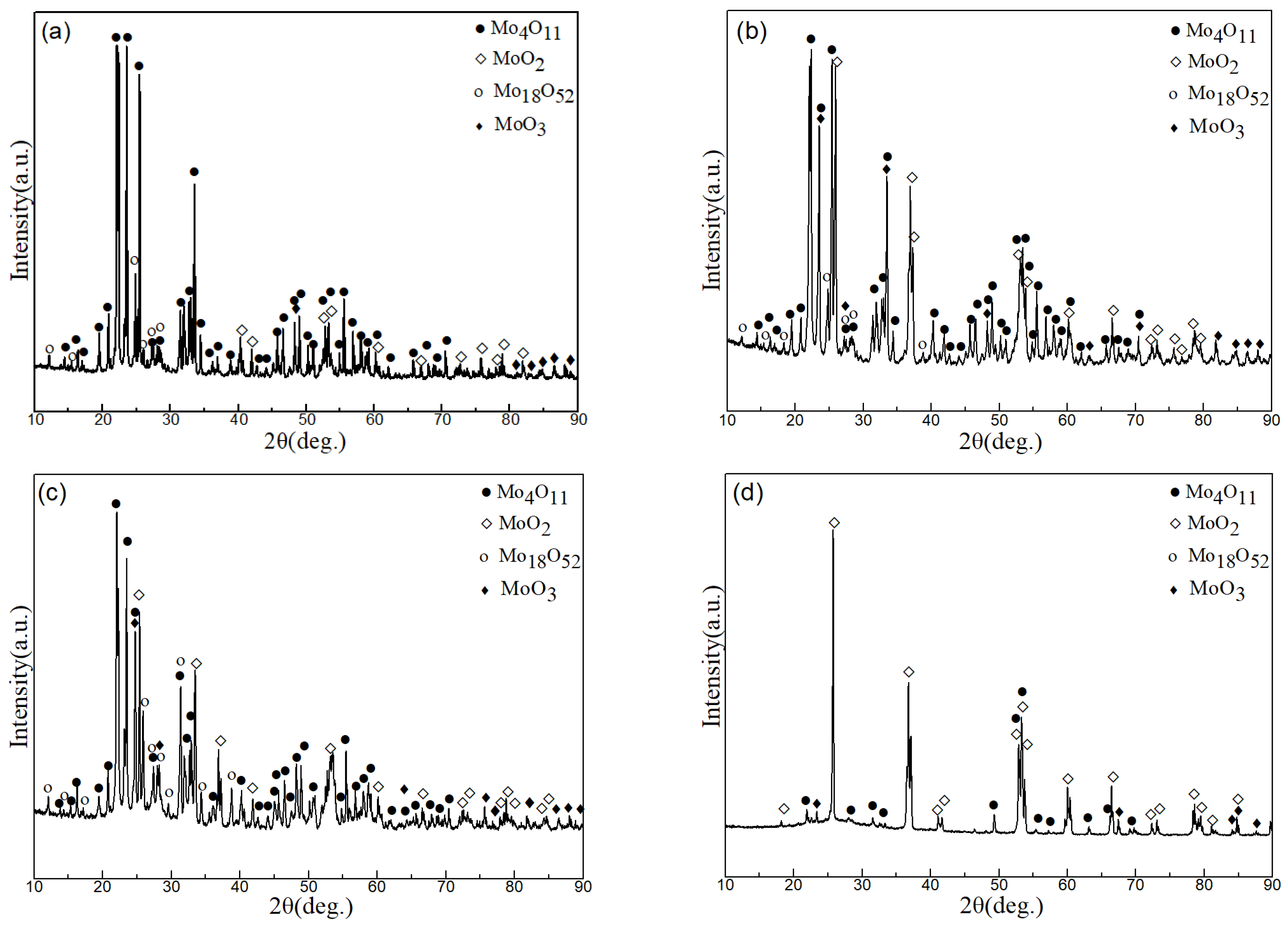
Figure 1. XRD patterns of MoOx targets at different sintering temperature, (a) 800 °C, (b) 900 °C, (c) 1000 °C, and (d) 1100 °C.
Coatings 12 01624 g001
Figure 2. SEM images of MoOx targets at different sintering temperature, (a) 800 °C, (b) 900 °C, (c) 1000 °C, and (d) 1100 °C.
Coatings 12 01624 g002
Figure 3. Optical micrographs of MoOx targets at different sintering temperature, (a) 800 °C, (b) 900 °C, (c) 1000 °C, and (d) 1100 °C.
Coatings 12 01624 g003aCoatings 12 01624 g003b
Figure 4. Cross section views of sputtered films using different sintered MoOx targets, (a) 800 °C, (b) 900 °C, (c) 1000 °C, and (d) 1100 °C.
Coatings 12 01624 g004
Figure 5. Resistivity, reflectivity, and transmissivity of sputtered films deposited with MoOx targets at different sintering temperatures.
Coatings 12 01624 g005
Publisher’s Note: MDPI stays neutral with regard to jurisdictional claims in published maps and institutional affiliations.