
A Comparative Study of Chloride Adsorption Ability and Corrosion Protection Effect in Epoxy Coatings of Various Layered Double Hydroxides

 ,
,
Abstract
:
1. Introduction
2. Experimental
2.1. Materials and Agents
2.2. LDHs Preparation
2.2.1. Changing the Divalent Cations
2.2.2. Changing the Divalent to Trivalent Cation Ratios
2.2.3. Changing the Hydrothermal Time
2.3. LDHs Sample Characterization
2.4. LDHs Chloride Adsorption Ability Evaluation
2.5. Coating Preparation
2.6. Coating Morphology and Roughness Characterization
2.7. Corrosion Protection Property Investigation
2.7.1. Electrochemical Impedance Spectroscopy (EIS) Test
2.7.2. Salt Spray Test
3. Results and Discussion
3.1. Characterization
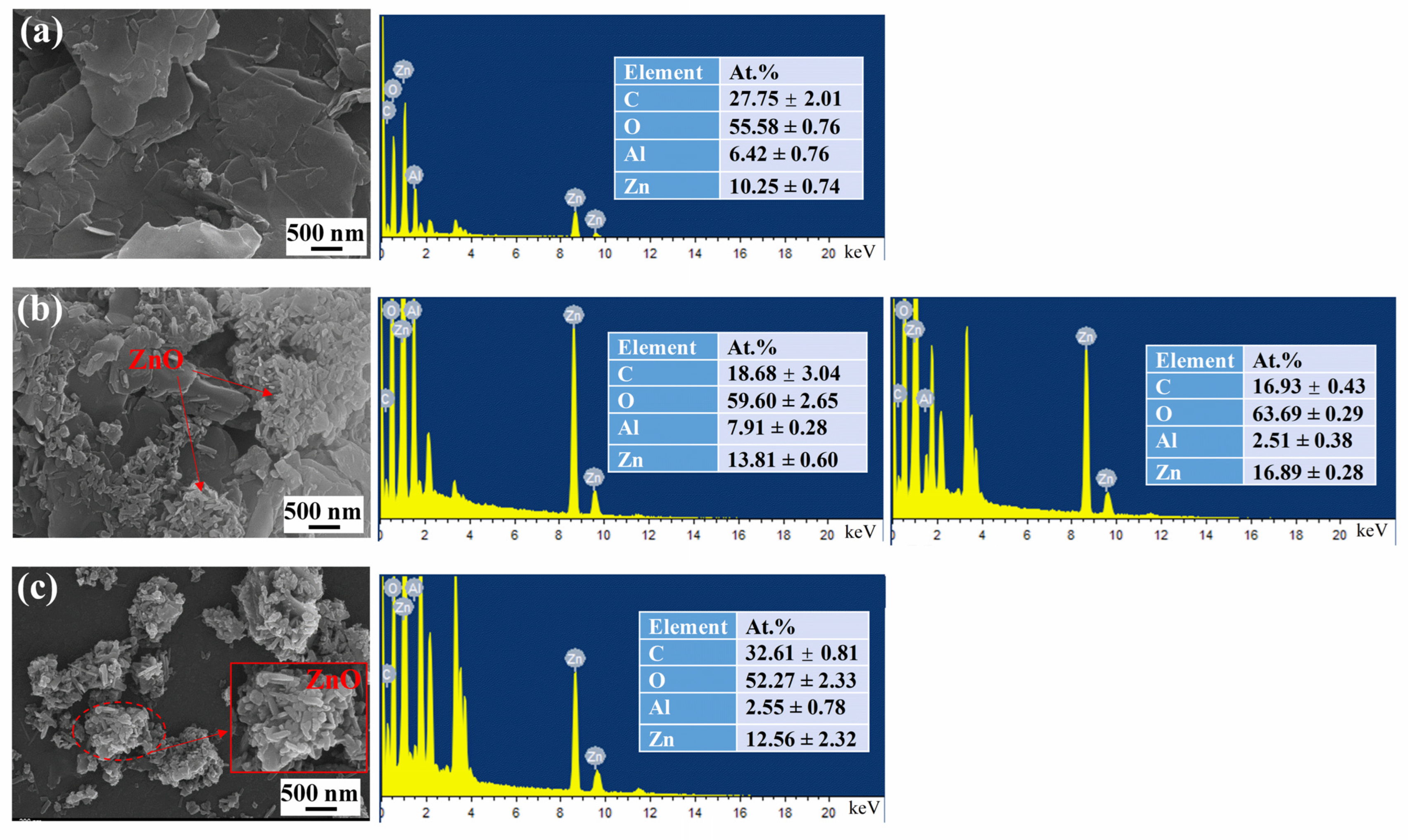
3.1.1. SEM and EDS Results
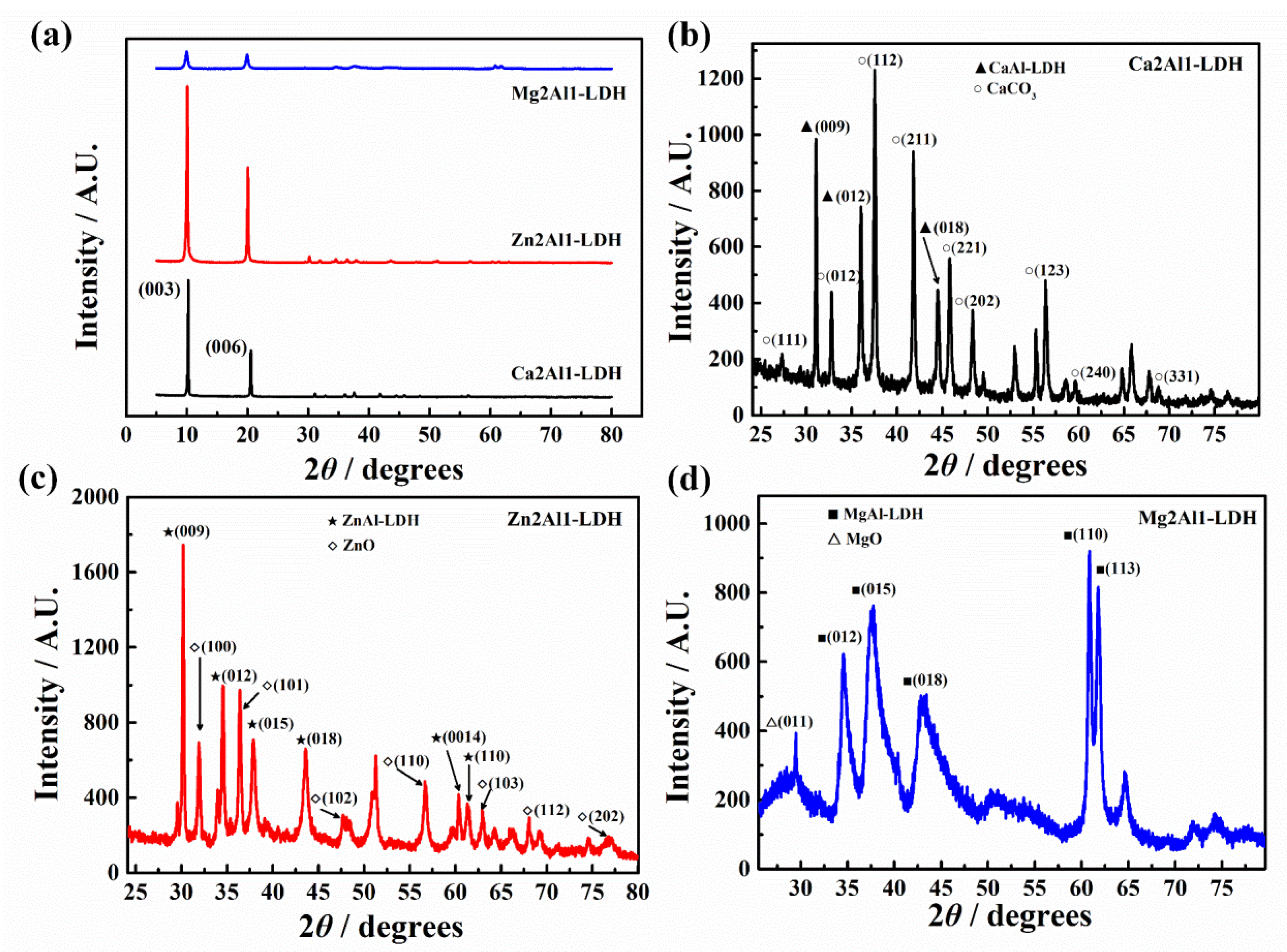
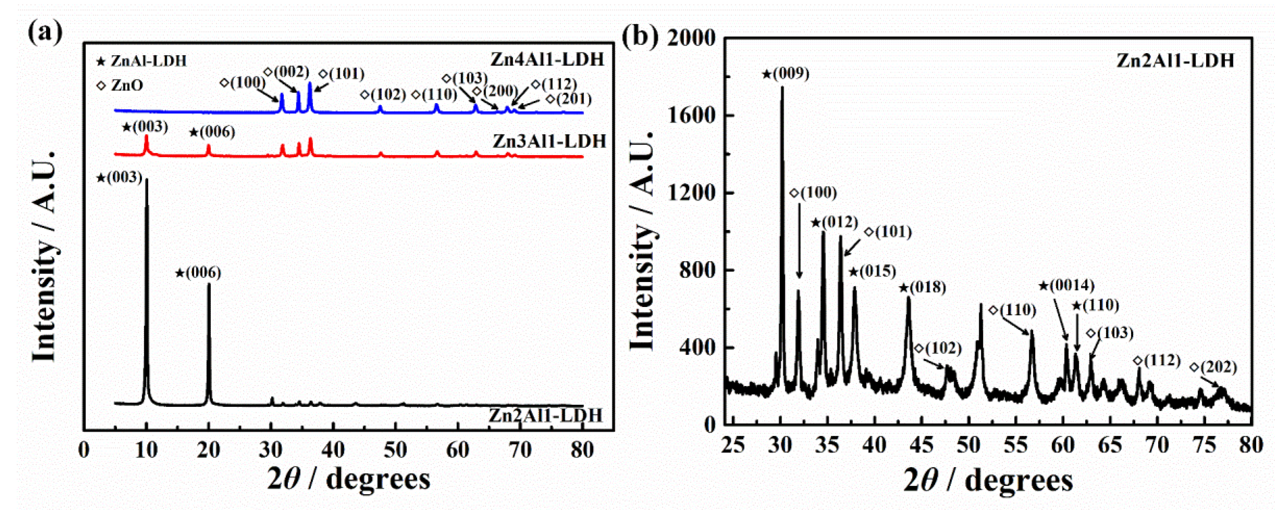
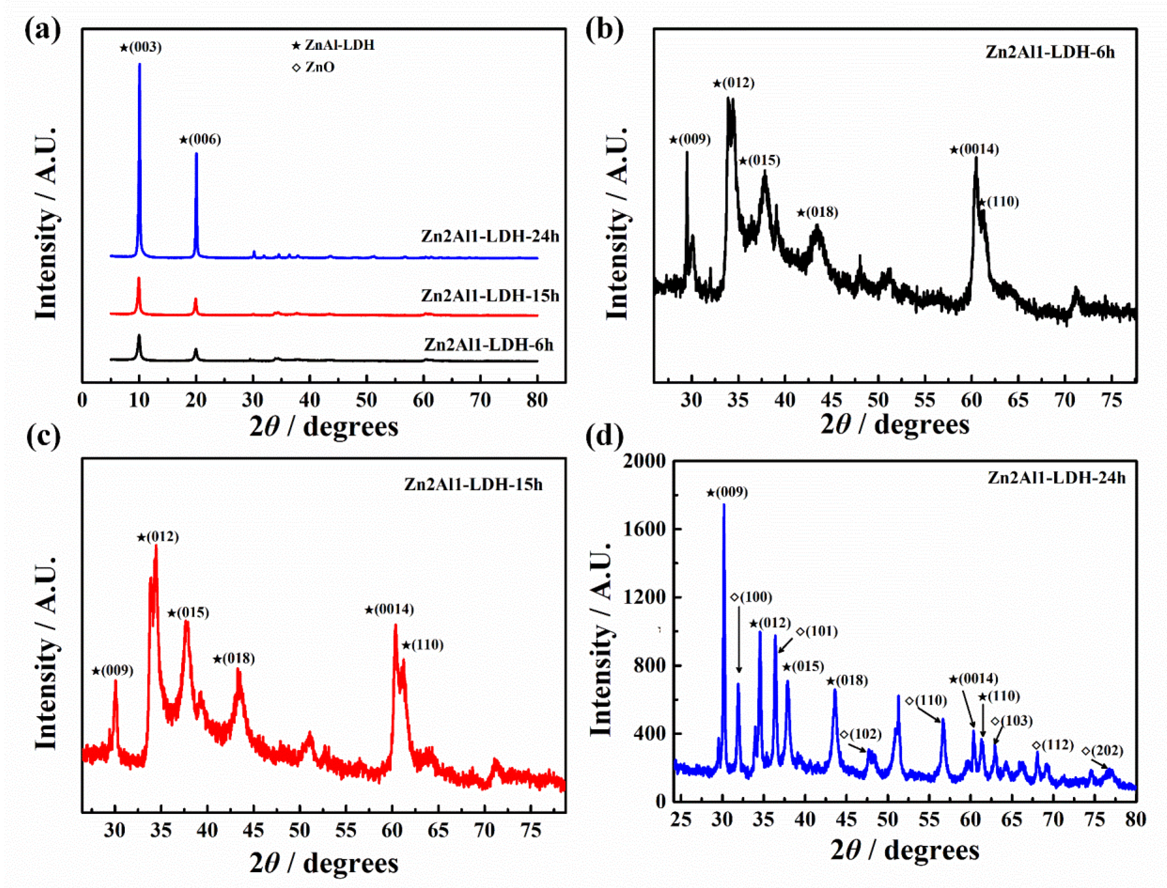
3.1.2. XRD Results
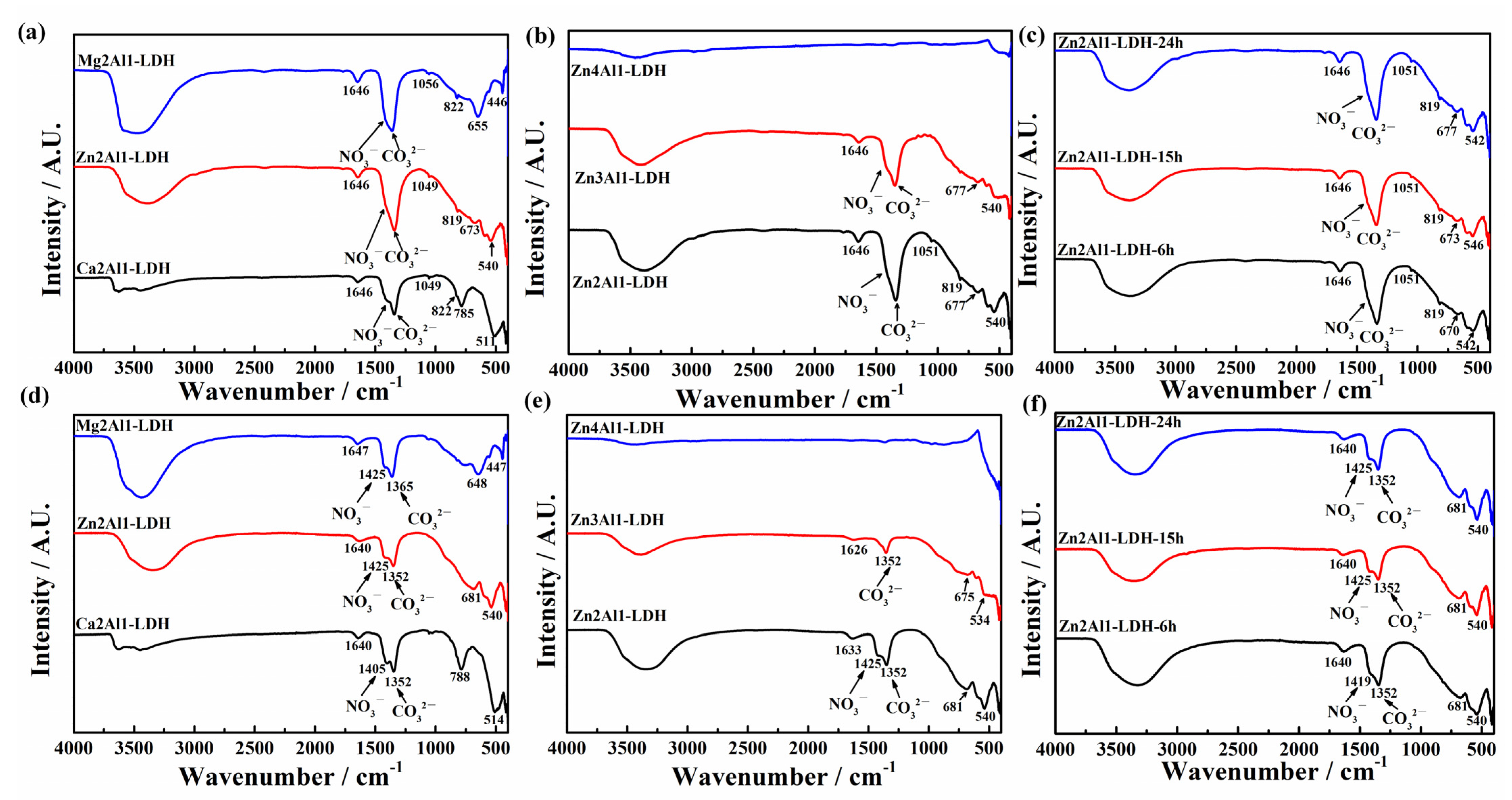
3.1.3. FTIR Results
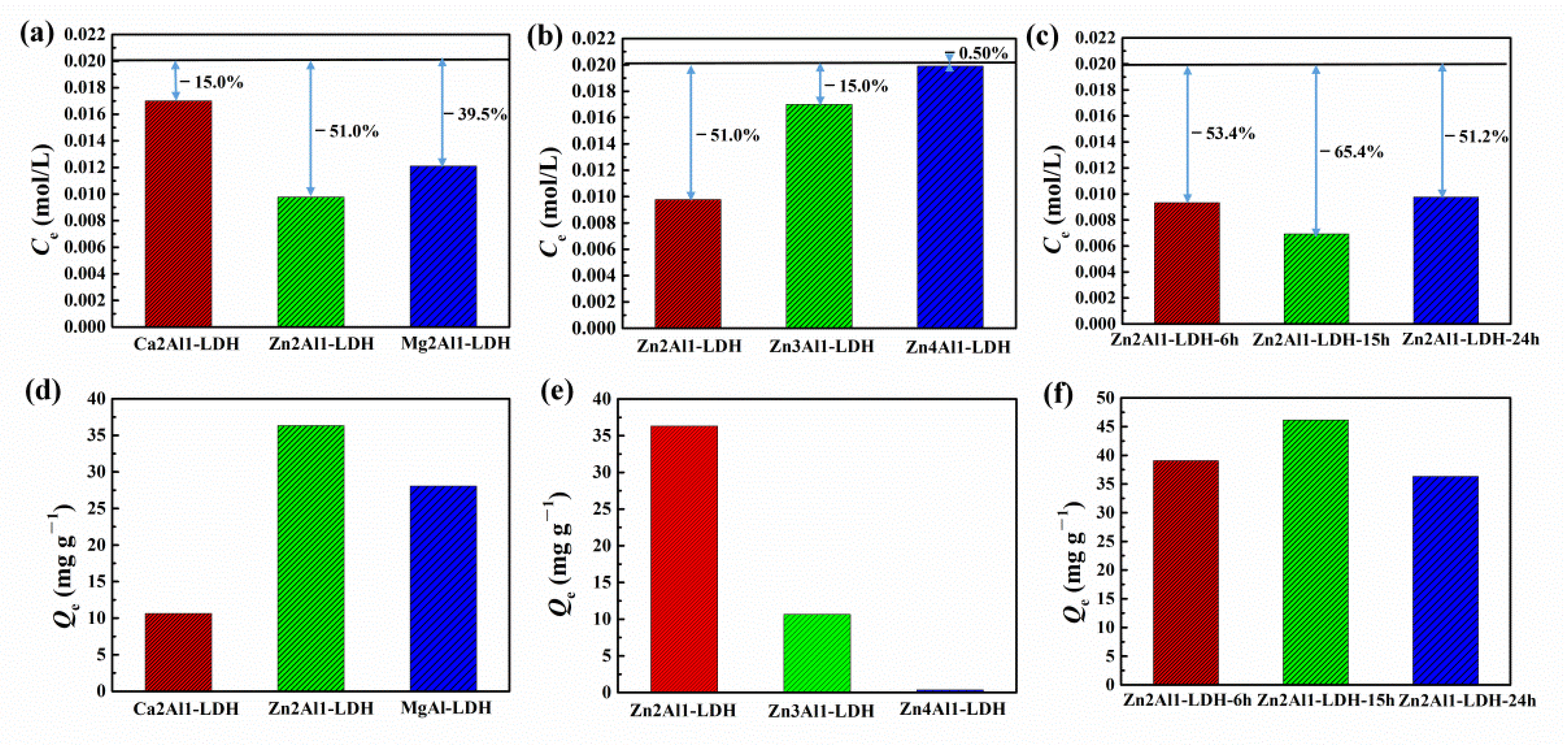
3.2. Chloride Adsorption Ability
3.3. Morphology Characterization and Corrosion Protection Property of the Coatings
3.3.1. Coating Morphology and Roughness Characterization
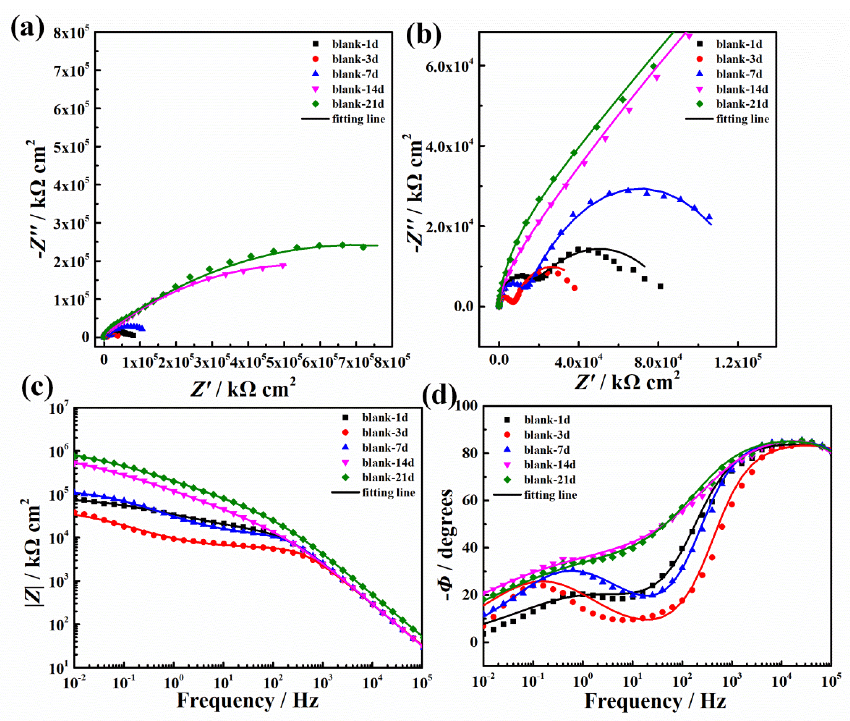
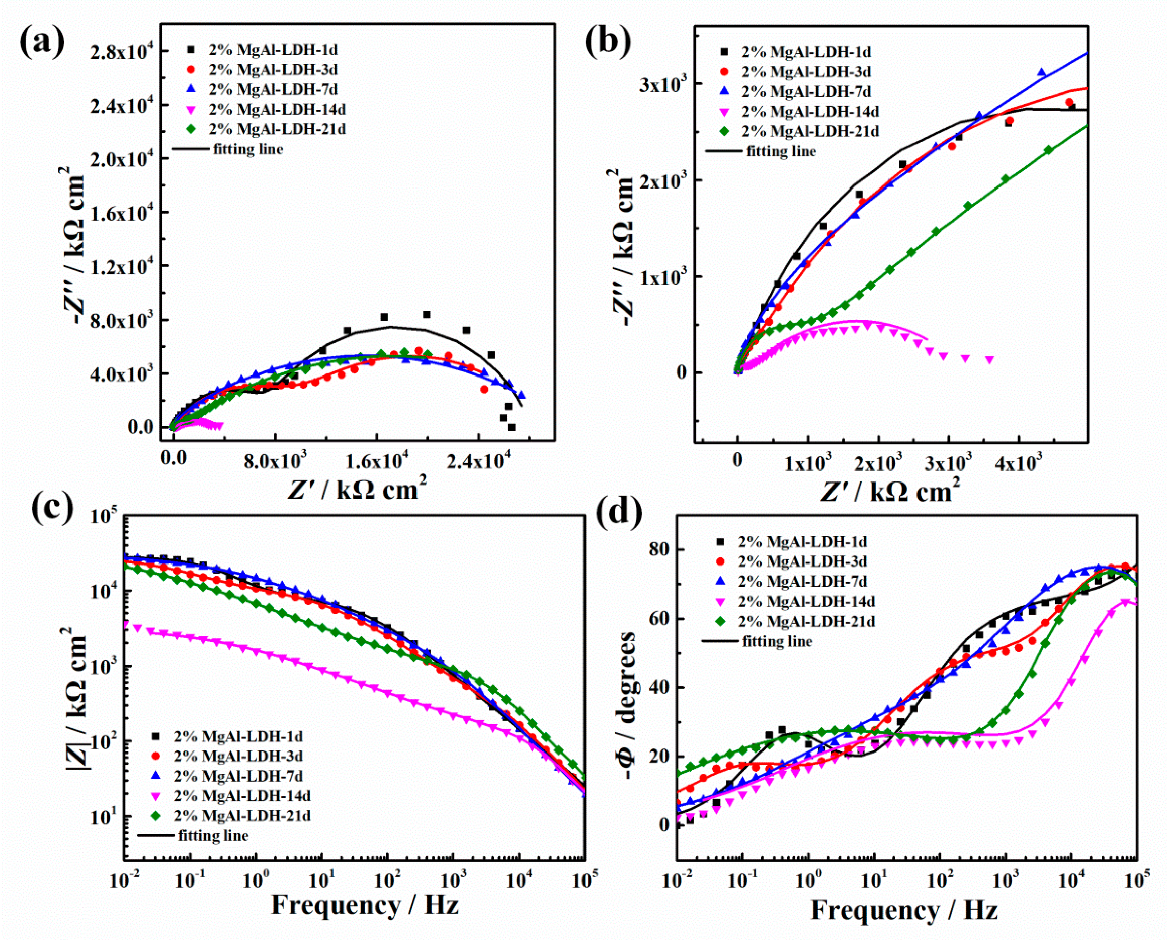
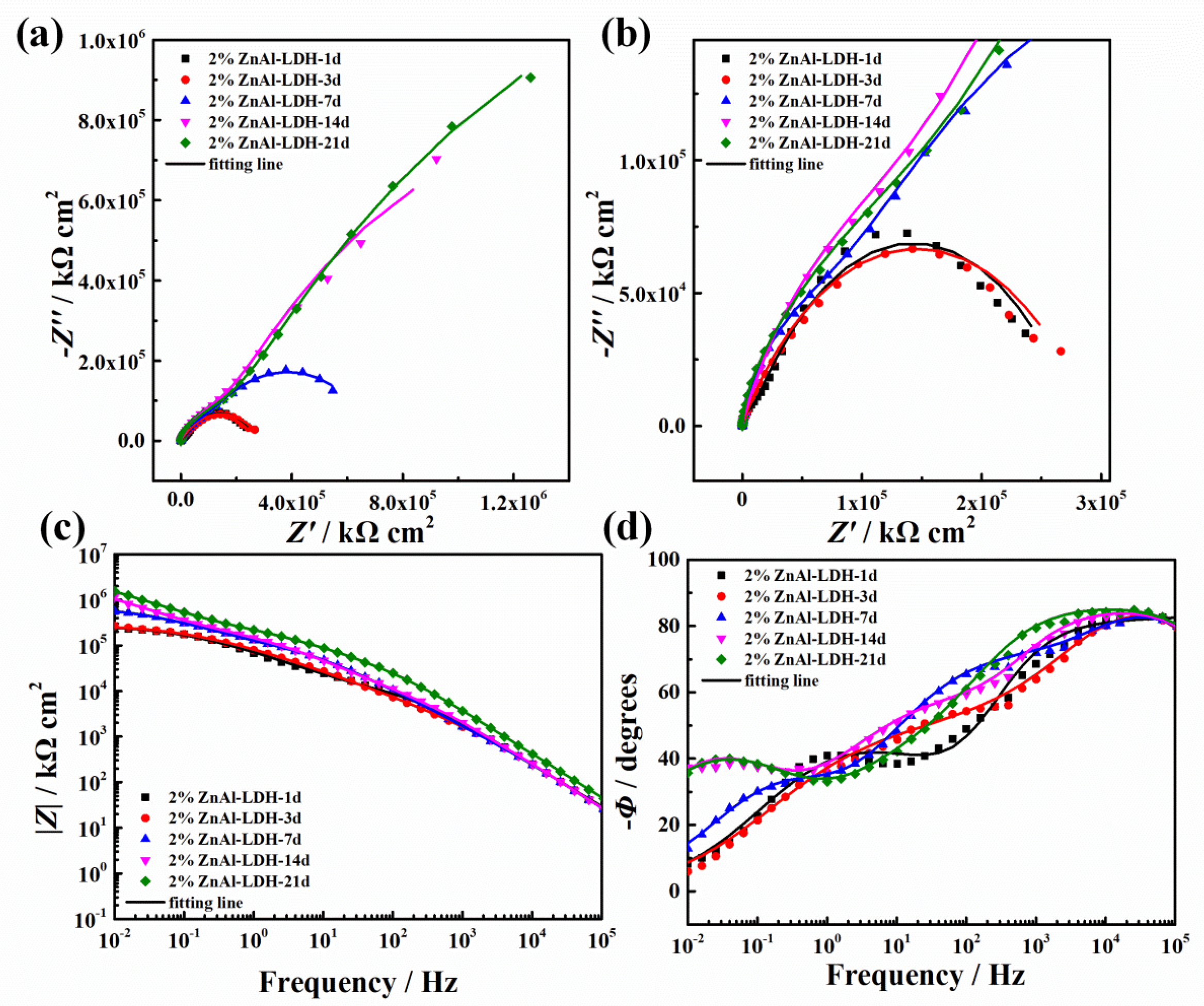
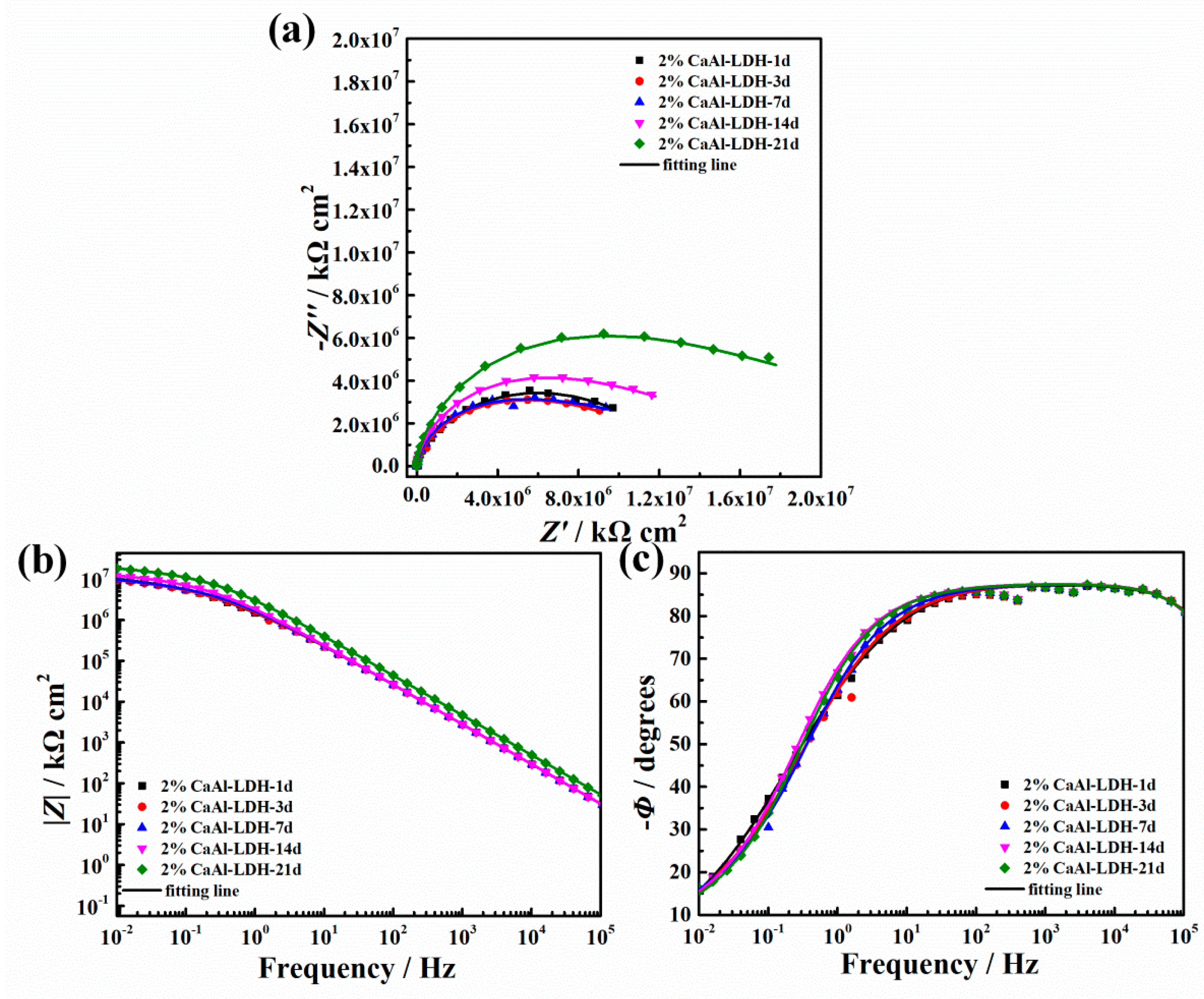
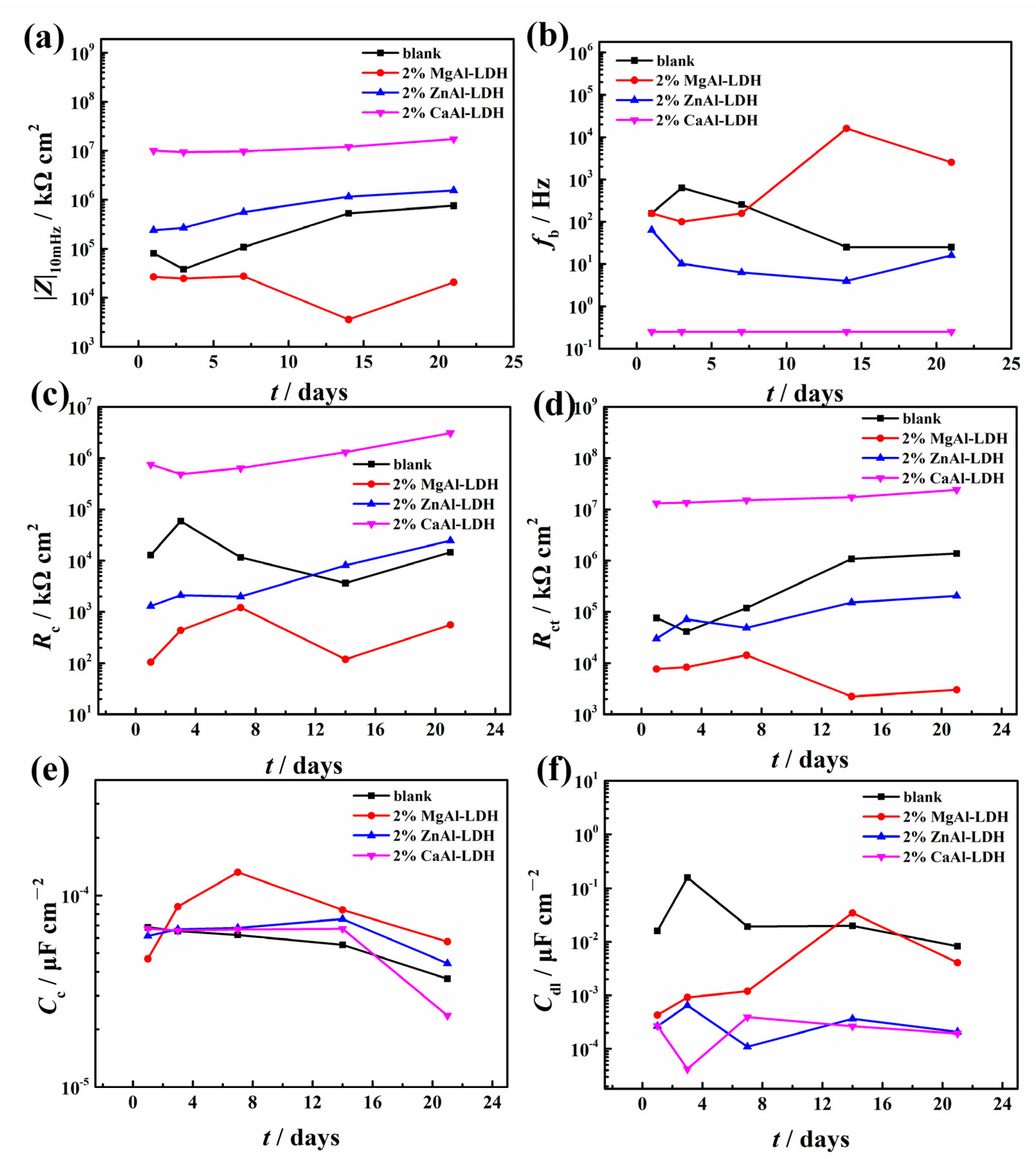
3.3.2. EIS Results
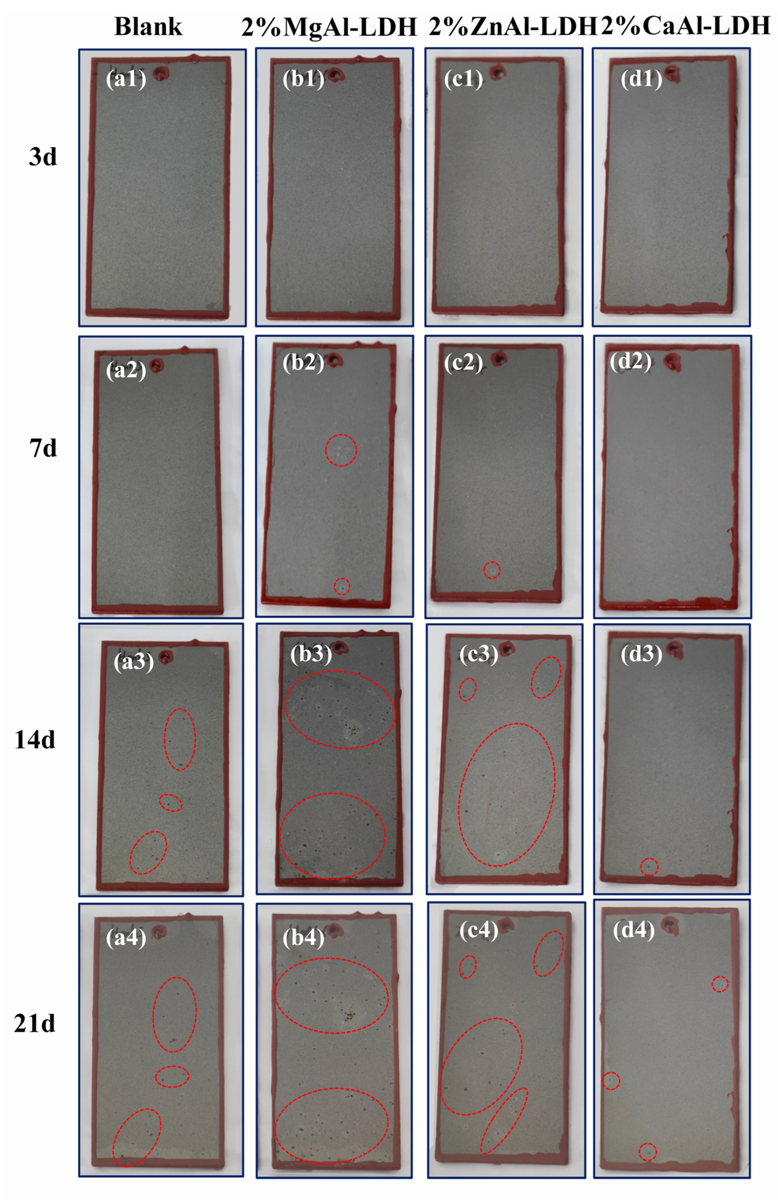
3.3.3. Salt Spray Test Results
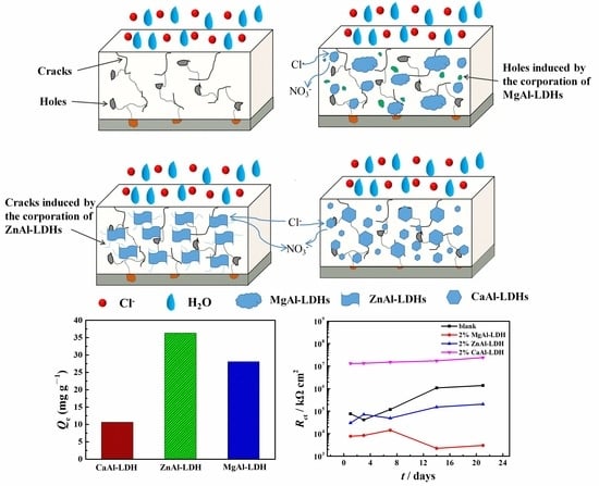
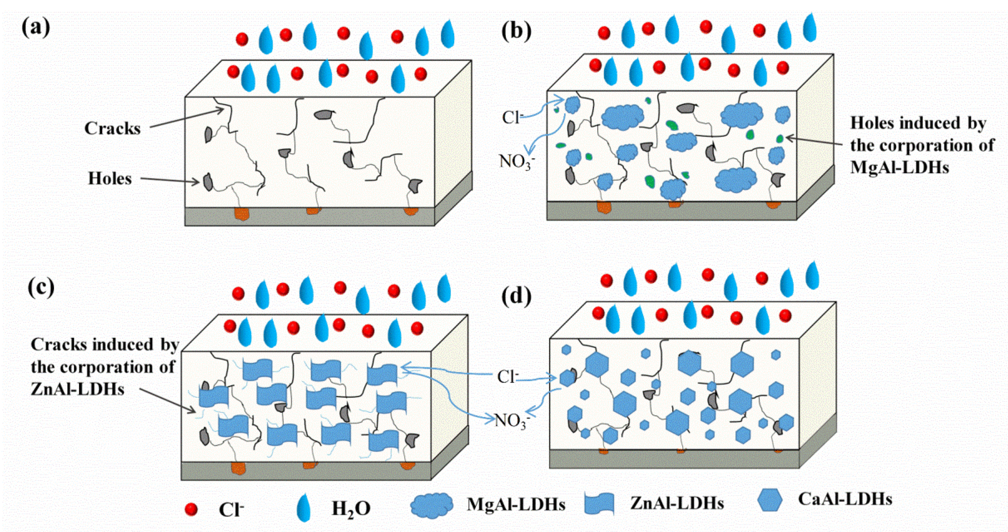
3.4. Corrosion Protection Mechanism
4. Conclusions
- (1)
- The influence of important synthesizing parameters including different divalent cations, divalent to trivalent cation ratios and hydrothermal time on the morphology, composition and structure was investigated. It was found that the increase of divalent to trivalent cation ratios and hydrothermal time led to the formation of more ZnO, resulting in the lower chloride adsorption ability.
- (2)
- The relationship between the chloride adsorption ability of LDHs synthesized with different parameters and the finally obtained corrosion protection property of the epoxy coatings was deeply explored. Although ZnAl-LDH presented higher chloride adsorption ability, the epoxy coating with the addition of CaAl-LDH showed a better corrosion protection effect. The result indicated that the observed corrosion property was not directly proportional to the measured chloride adsorption ability.
- (3)
- It can be concluded that the corrosion protection property was influenced more significantly by the dispersion state and physical barrier effect of the additions, which emphasizes the physical barrier role of LDHs rather than the chloride adsorption ability in coatings. However, the result may become different when corrosion inhibitors were intercalated in the LDH gallery, and we will focus on this point in the future work.
Author Contributions
Funding
Institutional Review Board Statement
Informed Consent Statement
Data Availability Statement
Conflicts of Interest
References
- Yohai, L.; Vázquez, M.; Valcarce, M. Phosphate ions as corrosion inhibitors for reinforcement steel in chloride-rich environments. Electrochim. Acta 2013, 102, 88–96. [Google Scholar] [CrossRef] [Green Version]
- Serdechnova, M.; Mohedano, M.; Kuznetsov, B.; Mendis, C.L.; Starykevich, M.; Karpushenkov, S.; Tedim, J.; Ferreira, M.; Blawert, C.; Zheludkevich, M. PEO coatings with active protection based on in-situ formed LDH-nanocontainer. J. Electrochem. Soc. 2016, 164, C36–C45. [Google Scholar] [CrossRef] [Green Version]
- Chen, C.; Qiu, S.; Cui, M.; Qin, S.; Yan, G.; Zhao, H.; Wang, L.; Xue, Q. Achieving high performance corrosion and wear resistant epoxy coatings via incorporation of noncovalent functionalized graphene. Carbon 2017, 114, 356–366. [Google Scholar] [CrossRef]
- Yabuki, A.; Okumura, K. Self-healing coatings using superabsorbent polymers for corrosion inhibition in carbon steel. Corros. Sci. 2012, 59, 258–262. [Google Scholar] [CrossRef]
- Liu, J.; Zhang, Y.; Yu, M.; Li, S.; Xue, B.; Yin, X. Influence of embedded ZnAlCe-NO3− layered double hydroxides on the anticorrosion properties of sol–gel coatings for aluminum alloy. Prog. Org. Coat. 2015, 81, 93–100. [Google Scholar] [CrossRef]
- Rodriguez, J.; Bollen, E.; Nguyen, T.D.; Portier, A.; Paint, Y.; Olivier, M.G. Incorporation of layered double hydroxides modified with benzotriazole into an epoxy resin for the corrosion protection of Zn-Mg coated steel. Prog. Org. Coat. 2020, 149, 105894. [Google Scholar] [CrossRef]
- Mei, Y.; Xu, J.; Jiang, L.; Tan, Q. Enhancing corrosion resistance of epoxy coating on steel reinforcement by aminobenzoate intercalated layered double hydroxides. Prog. Org. Coat. 2019, 134, 288–296. [Google Scholar] [CrossRef]
- Tabish, M.; Zhao, J.; Wang, J.; Anjum, M.J.; Qiang, Y.; Yang, Q.; Mushtaq, M.A.; Yasin, G. Improving the corrosion protection ability of epoxy coating using CaAl LDH intercalated with 2-mercaptobenzothiazole as a pigment on steel substrate. Prog. Org. Coat. 2022, 165, 106765. [Google Scholar] [CrossRef]
- Zaghloul, M.; Mohamed, Y.; El-Gamal, H. Fatigue and tensile behaviors of fiber-reinforced thermosetting composites embedded with nanoparticles. J. Compos. Mater. 2018, 53, 709–718. [Google Scholar] [CrossRef]
- Zaghloul, M. Mechanical properties of linear low-density polyethylene fire-retarded with melamine polyphosphate. J. Appl. Polym. Sci. 2018, 135, 46770. [Google Scholar] [CrossRef]
- Xue, B.; Yu, M.; Liu, J.; Li, S.; Xiong, L.; Kong, X. Synthesis of inhibitor nanocontainers with two-dimensional structure and their anticorrosion action in sol-gel coating on AA2024-T3 aluminum alloy. J. Electrochem. Soc. 2017, 164, C641–C652. [Google Scholar] [CrossRef]
- Nguyen, T.D.; Nguyen, A.S.; Tran, B.A.; Vu, K.O.; Tran, D.L.; Phan, T.T.; Scharnagl, N.; Zheludkevich, M.L. To TXH Molybdate intercalated hydrotalcite/graphene oxide composite as corrosion inhibitor for carbon steel. Surf. Coat. Technol. 2020, 399, 126165. [Google Scholar] [CrossRef]
- Zhang, M.; Xu, F.; Lin, D.; Peng, J.; Zhu, Y. Wang H A smart anti-corrosion coating based on triple functional fillers. Chem. Eng. J. 2022, 446, 137078. [Google Scholar] [CrossRef]
- Cao, Y.; Dong, S.; Zheng, D.; Wang, J.; Zhang, X.; Du, R.; Song, G.; Lin, C. Multifunctional inhibition based on layered double hydroxides to comprehensively control corrosion of carbon steel in concrete. Corros. Sci. 2017, 126, 166–179. [Google Scholar] [CrossRef]
- Cao, Y.; Zheng, D.; Dong, S.; Zhang, F.; Lin, J.; Wang, C.; Lin, C. A composite corrosion inhibitor of MgAl layered double hydroxides co-intercalated with hydroxide and organic anions for carbon steel in simulated carbonated concrete pore solutions. J. Electrochem. Soc. 2019, 166, C3106–C3113. [Google Scholar] [CrossRef]
- Cao, Y.; Zheng, D.; Luo, J.; Zhang, F.; Dong, S.; Pan, J.; Lin, C. Insight into the Fabrication of ZnAl Layered Double Hydroxides Intercalated with Organic Anions and Their Corrosion Protection of Steel Reinforced Concrete. J. Electrochem. Soc. 2019, 166, C617–C623. [Google Scholar] [CrossRef]
- Cao, Y.; Zheng, D.; Li, X.; Lin, J.; Wang, C.; Dong, S.; Lin, C. Enhanced corrosion resistance of superhydrophobic layered double hydroxide films with long-term stability on Al substrate. ACS Appl. Mater. Interfaces 2018, 10, 15150–15162. [Google Scholar] [CrossRef]
- Cao, Y.; Zheng, D.; Luo, J.; Zhang, F.; Wang, C.; Dong, S.; Ma, Y.; Liang, Z.; Lin, C. Enhanced corrosion protection by Al surface immobilization of in-situ grown layered double hydroxide films co-intercalated with inhibitors and low surface energy species. Corros. Sci. 2020, 164, 108340. [Google Scholar] [CrossRef]
- Cao, Y.; Zheng, D.; Lin, C. Construction of ecofriendly anticorrosive composite film ZnAl-LDH by modification of lignin onAA7075 surface. Mater. Corros. 2021, 72, 1595–1606. [Google Scholar] [CrossRef]
- Iqbal, M.A.; Sun, L.; Asghar, H.; Fedel, M. Chlorides Entrapment Capability of Various In-Situ Grown NiAl-LDHs: Structural and Corrosion Resistance Properties. Coatings 2020, 10, 384. [Google Scholar] [CrossRef]
- Wang, Y.; Huang, Q.; Zhou, B.; Yuan, Z.; Wei, Y.; Fujita, T. Corrosion Protection of 6061 Aluminum Alloys by Sol-Gel Coating Modified with ZnLaAl-LDHs. Coatings 2021, 11, 478. [Google Scholar] [CrossRef]
- Cao, Y.; Fang, S.; Chen, K.; Qi, H.; Zhang, X.; Huang, C.; Wang, J.; Liu, J. Insight into the Preparation of MgAl-Layered Double Hydroxide (LDH) Intercalated with Nitrates and Chloride Adsorption Ability Study. Appl. Sci. 2022, 12, 4492. [Google Scholar] [CrossRef]
- Chen, M.; Wu, F.; Yu, L.; Cai, Y.; Chen, H.; Zhang, M. Chloride binding capacity of LDHs with various divalent cations and divalent to trivalent cation ratios in different solutions. CrystEngComm 2019, 21, 6790–6800. [Google Scholar] [CrossRef]
- Zhu, A.; Wang, H.; Xue, M.; Cao, Y.; He, J.; Lu, W.; Xu, Y.; Zeng, B.; Yuan, C.; Chen, G.; et al. Preparation of two-dimensional boron nitride-layered double hydroxide hybrid to reinforce the corrosion protection of the epoxy coating. Mater. Corros. 2022, 73, 1444–1458. [Google Scholar] [CrossRef]
- ISO 16773-2016; Electrochemical Impedance Spectroscopy (EIS) on Coated and Uncoated Metallic Specimens. ISO: Geneva, Switzerland, 2016.
- GB/T 1771-2007; Paints and Varnishes—Determination of Resistance to Neutral Salt Spray (Fog). China National Standardization Administration: Beijing, China, 2007.
- Zheludkevich, M.L.; Poznyak, S.K.; Rodrigues, L.M.; Raps, D.; Hack, T.; Dick, L.F.; Nunes, T.; Ferreira, M. Active protection coatings with layered double hydroxide nanocontainers of corrosion inhibitor. Corros. Sci. 2010, 52, 602–611. [Google Scholar] [CrossRef]
- Zhou, M.; Pang, X.; Wei, L.; Gao, K. Insitu grown superhydrophobic Zn–Al layered double hydroxides films on magnesium alloy to improve corrosion properties. Appl. Surf. Sci. 2015, 337, 172–177. [Google Scholar] [CrossRef]
- Guo, X.; Xu, S.; Zhao, L.; Lu, W.; Zhang, F.; Evans, D.G.; Duan, X. One-step hydrothermal crystallization of a layered double hydroxide/alumina bilayer film on aluminum and its corrosion resistance properties. Langmuir 2009, 25, 9894–9897. [Google Scholar] [CrossRef]
- Hu, T.; Ouyang, Y.; Xie, Z.; Wu, L. One-pot scalable in situ growth of highly corrosion-resistant MgAl-LDH/MBT composite coating on magnesium alloy under mild conditions. J. Mater. Sci. Technol. 2021, 92, 225–235. [Google Scholar] [CrossRef]
- Zuo, J.D.; Peng, Z.C.; Dong, B.Q.; Wang, Y.S. In situ growth of corrosion resistant Mg-Fe layered double hydroxide film on Q235 steel. J. Colloid Interf. Sci. 2021, 610, 202–212. [Google Scholar] [CrossRef]
- He, Q.Q.; Zhou, M.J.; Hu, J.M. Electrodeposited Zn-Al layered double hydroxide films for corrosion protection of aluminum alloys. Electrochim. Acta 2020, 355, 136796. [Google Scholar] [CrossRef]
- Salak, A.N.; Tedim, J.; Kuznetsova, A.I.; Zheludkevich, M.L.; Ferreira, M. Anion exchange in Zn–Al layered double hydroxides: In situ X-ray diffraction study. Chem. Phys. Lett. 2010, 495, 73–76. [Google Scholar] [CrossRef]
- Wu, Y.; Wu, L.; Zheludkevich, M.L.; Chen, Y.; Serdechnova, M.; Yao, W.; Blawert, C.; Atrens, A.; Pan, F. MgAl-V2O74- LDHs/(PEI/MXene)10 composite film for magnesium alloy corrosion protection. J. Mater. Sci. Technol. 2021, 91, 28–39. [Google Scholar] [CrossRef]
- Cao, Y.; Zheng, D.; Lin, C. Effect of physical barrier and anion-exchange process of nitrate-intercalated ZnAl layered double hydroxide films grown on Al on corrosion protection. Surf. Coat. Technol. 2021, 421, 127436. [Google Scholar] [CrossRef]
- Tedim, J.; Kuznetsova, A.; Salak, A.N.; Montemor, F.; Snihirova, D.; Pilz, M.; Zheludkevich, M.L.; Ferreira, M. Zn–Al layered double hydroxides as chloride nanotraps in active protective coatings. Corros. Sci. 2012, 55, 1–4. [Google Scholar] [CrossRef]
- Vieira, D.; Salak, A.; Ferreira, M.; Vieira, J.M.; Brett, C. Ce-substituted Mg-Al layered double hydroxides to prolong the corrosion protection lifetime of aluminium alloys. Appl. Surf. Sci. 2022, 573, 151527. [Google Scholar] [CrossRef]
- Ren, L.; Gao, S.; Chen, Z.; Jiang, D.; Huang, H. Facile preparation of wear-resistant and anti-corrosion films on magnesium alloy. Surf. Eng. 2022, 38, 22–29. [Google Scholar] [CrossRef]
- Li, Z.; Ba, Z.; Wang, T.; Kuang, J.; Jia, Y. Fabrication and characterization of Mg–Mn hydrotalcite films on pure Mg substrates. Mater. Res. Express 2019, 6, 116440. [Google Scholar] [CrossRef]
- Zahedi, A.V.; Zhao, J.; Anjum, M.J.; Wei, S.; Wang, W.; Zhao, Z. The effect of cerium cation on the microstructure and anti-corrosion performance of LDH conversion coatings on AZ31 magnesium alloy. J. Alloys Compd. 2020, 821, 153248. [Google Scholar] [CrossRef]
- Xu, J.; Song, Y.; Zhao, Y.; Jiang, L.; Mei, Y.; Chen, P. Chloride removal and corrosion inhibitions of nitrate, nitrite-intercalated Mg Al layered double hydroxides on steel in saturated calcium hydroxide solution. Appl. Clay Sci. 2018, 163, 129–136. [Google Scholar] [CrossRef]
- Wei, J.; Xu, J.; Mei, Y.; Tan, Q. Chloride adsorption on aminobenzoate intercalated layered double hydroxides: Kinetic, thermodynamic and equilibrium studies. Appl. Clay Sci. 2020, 187, 105495. [Google Scholar] [CrossRef]
- Tabish, M.; Zhao, J.; Kumar, A.; Yan, J.; Wang, J.; Shi, F.; Zhang, J.; Peng, L.; Mushtaq, M.A.; Yasin, G. Developing epoxy-based anti-corrosion functional nanocomposite coating with CaFe-Tolyl-triazole layered double hydroxide@g-C3N4 as nanofillers on Q235 steel substrate against NaCl corrosive environment. Chem. Eng. J. 2022, 450, 137624. [Google Scholar] [CrossRef]
- Xu, T.; Zhao, Y.; Zhou, J.; Hu, J. Composite nanocontainers synthesized by in-situ growth of metal organic frameworks on layered double hydroxides having both passive and active protecting capabilities. Prog. Org. Coat. 2022, 164, 106695. [Google Scholar] [CrossRef]
- Mohammadi, I.; Shahrabi, T.; Mahdavian, M.; Izadi, M. Construction of an epoxy coating with excellent protection performance on the AA 2024-T3 using ion-exchange materials loaded with eco-friendly corrosion inhibitors. Prog. Org. Coat. 2022, 166, 106786. [Google Scholar] [CrossRef]


| Items | BYK110 | BYK320 | BYK 580 |
|---|---|---|---|
| Solvent | Propylene Glycol Methyl Ether Acetate/Alkyl Benzene (1/1) | Petroleum Solvent /Propylene Glycol Methyl Ether Acetate (9/1) | Hydrocarbon Mixture (Paraffin Series, Naphthenic Series) |
| Density (20 °C g/mL) | 1.03 | 0.86 | 0.81 |
| Non volatile matter % | 52 | 52 | 5 |
| Flash point (°C) | 42 | 38 | >95 |
| Items | 6101 Epoxy Resin |
|---|---|
| Epoxy equivalent (g/eq) | 210–240 |
| softening point (°C) | 12–20 |
| viscosity (25 °C mPa·s 80% Xylene solution) | 200–400 |
| Saponifiable chlorine (%) | <=0.3 |
| Inorganic chlorine (ppm) | <=180 |
| Items | 2519 Hardener |
|---|---|
| Viscosity (25 °C mPa·s) | 185 |
| Density (25 °C g/mL) | 1.01 |
| Flash point (°C) | >100 |
| Amine value (mg KOH/g) | 315 |
Publisher’s Note: MDPI stays neutral with regard to jurisdictional claims in published maps and institutional affiliations. |
© 2022 by the authors. Licensee MDPI, Basel, Switzerland. This article is an open access article distributed under the terms and conditions of the Creative Commons Attribution (CC BY) license (https://creativecommons.org/licenses/by/4.0/).
Share and Cite
Cao, Y.; Wang, J.; Chen, K.; Zhang, X.; Zhang, B.; Fang, S.; Liang, Y.; Huang, C.; Wang, X. A Comparative Study of Chloride Adsorption Ability and Corrosion Protection Effect in Epoxy Coatings of Various Layered Double Hydroxides. Coatings 2022, 12, 1631. https://doi.org/10.3390/coatings12111631
Cao Y, Wang J, Chen K, Zhang X, Zhang B, Fang S, Liang Y, Huang C, Wang X. A Comparative Study of Chloride Adsorption Ability and Corrosion Protection Effect in Epoxy Coatings of Various Layered Double Hydroxides. Coatings. 2022; 12(11):1631. https://doi.org/10.3390/coatings12111631
Chicago/Turabian StyleCao, Yanhui, Jingjing Wang, Kaifeng Chen, Xinyue Zhang, Bing Zhang, Shuo Fang, Yu Liang, Congshu Huang, and Xinyu Wang. 2022. "A Comparative Study of Chloride Adsorption Ability and Corrosion Protection Effect in Epoxy Coatings of Various Layered Double Hydroxides" Coatings 12, no. 11: 1631. https://doi.org/10.3390/coatings12111631