Article

Visual Inspection of the Heavy-Duty Paint Systems Used in Steel Bridges for Assessing the Level of Fire Damage

1
Department of Civil Engineering, Pusan National University, Busan 46241, Korea
2
Technology Innovation Team, Busan Infrastructure Corporation, Busan 47132, Korea
3
Seismic Simulation Test Center, Pusan National University, Yangsan 50612, Korea
4
FC-BGA Business Execution Team, LG Innotek, Gumi 39419, Korea
*
Author to whom correspondence should be addressed.
Coatings 2022, 12(11), 1697; https://doi.org/10.3390/coatings12111697
Submission received: 26 September 2022 / Revised: 28 October 2022 / Accepted: 2 November 2022 / Published: 8 November 2022

Abstract

:
After a fire on a steel bridge, a visual inspection is necessary to rapidly determine the need for an emergency response to ensure the structural safety of the bridge and decide whether to re-open the bridge to traffic. In this study, the visual inspection methods of assessing the coated surface were reviewed, as they are crucial for the rapid estimation of the steel temperature reached during the fire, which, in turn, is required for the safety assessment of steel bridges after a fire. An electric furnace heating test was conducted on the steel specimens coated with four types of heavy-duty paint systems for steel bridges, viz., urethane, siloxane, ceramic, and fluorocarbon. The heating temperatures and durations used in the test were 100, 150, 200, 250, 300, 400, 500, and 600 °C at 30 and 60 min. Based on the heating temperature and duration, the paint-film surface conditions (discoloration, blistering, cracking, and delamination) were visually inspected for a qualitative analysis, and factors such as color difference, gloss retention, and pull-off adhesion were quantitatively analyzed. The visual inspection methods used to estimate the temperature of the paint film were reviewed. In addition, considering the reduction in the tension strength of the steel material and the coating durability performance according to the fire temperature, the determinants of the traffic stop–reopening timeline and the repair and reuse of the painting system based on the visual field inspection after a fire were suggested.

1. Introduction

The increase in the construction of numerous long-span overpass bridges in urban areas has led to incidents of various accidents. Notably, with the increasing traffic of special-purpose vehicles, such as heavy vehicles and oil tankers, the potential sources of large-scale fires and fire accidents with large-scale damage caused by the overturning or falling of these vehicles have increased [1,2,3,4]. Fire accidents on bridges in urban areas incur direct damage, such as the loss of human life and repair costs, and consequent secondary damage, such as traffic congestion or an increased cost of distribution. This secondary damage may incur significantly large-scale economic losses. For instance, the cost to repair the damage due to the fire on the lower part of the Bucheon Overpass Bridge of the Seoul Beltway in 2010 was ~KRW 15.4 billion, and the cost of the secondary damage was ~KRW 219.8 billion [5]. To reduce the cost of secondary damage, rapid decision-making is critical regarding traffic control or the scope of repair of the bridge after the damage caused by bridge fires.
In the case of bridge fires, the impacts of the fire’s intensity, such as its temperature and duration, on the mechanical properties of concrete and steel vary [6,7,8,9]. Concrete, when exposed to fire, changes its color depending on the temperature; at 300 °C–600 °C, it turns pink or red; at 600 °C–900 °C, it is whitish-grey; and at 1000 °C, it is buff-colored. Due to the temperature dependence of the concrete surface color, as shown in Table 1, the temperature and the reduction in compressive strength of concrete can be roughly estimated via a visual inspection of the color change after the onset of the fire [10,11]. Meanwhile, for steel, the temperature-induced color-change is insignificant, thereby preventing the estimation of elevated temperatures less than 600 °C through visual inspection, as shown in Table 2. This necessitates long-term and high-cost inspection involving non-destructive and destructive tests of fire-damaged steel to evaluate the post-fire safety of the steel bridge.
Paint coatings have been widely used in steel bridges to prevent them from corrosion attack. In Korea, >99% of steel bridges are coated with paint. Thus, the impact of a fire’s intensity on painted steel bridges can be estimated via a visual inspection of the temperature-induced, paint surface color-change after the onset of a fire. Since the 2000s, heavy-duty-painting systems have been the most widely used coating system for steel bridges in Korea.
The color change property of thermochromic materials can be employed to alert concerned parties of visible damage due to overheating. Thermochromic materials have received much attention because of their potential applications as visible temperature sensors in a wide range of devices, such as aeronautical engine components, household appliances, hotplates, and furnaces [12,13,14,15]. However, little attention has been paid to the temperature-induced color-change of the coating systems used in steel bridges, and no related literature is available.
In this study, a correlation between visible morphological changes in heavy-duty painting systems and temperature is experimentally investigated to develop a simple and rapid visual inspection method for assessing fire damage to steel bridges. In the experiment, steel specimens were prepared by coating them with all types of heavy-duty painting systems for steel bridges: urethane, siloxane, ceramic, and fluorocarbon, of the Korean Construction Specification (KCS 14 31 40) [16]. An electric furnace heating test was conducted (at temperatures of 100, 150, 200, 250, 300, 400, 500, and 600 °C and heating durations of 30 and 60 min). The changes in the surface properties of the four paint-coated steel systems were examined for varying heating temperatures and durations. The images showing the changes in the surface conditions are presented as indicators for estimating the elevated temperature during a fire (or fire temperature). In addition, further analyses were performed on coating durability performance together with the use of electrochemical impedance spectroscopy (EIS), environmental scanning electron microscopy (E-SEM), and Fourier-transform infrared (FT-IR) spectroscopy to determine the possibility of reusing the coating after fire damage.

2. Experimental Procedure

2.1. Preparation of Painted Steel Specimens

To prepare the specimens, small steel plates were obtained by cutting a 3 mm thick SS275 structural steel plate to the dimensions of 70 × 150 mm. The cut plates were blasted on the surfaces (Sa 2 1/2) [17] and then coated with urethane, siloxane, ceramic, and fluorocarbon, following the Korean Construction Specification (KCS 14 31 40: 2019 Paint Coating). The respective plates were labeled: U, S, C, and F.
The material properties and chemical compositions of the SS275 steel on the mill sheet are presented in Table 3 and Table 4, respectively. The specifications of the painting system types used in the test are listed in Table 5, and the appearances of the final painted steel specimens are shown in Figure 1.

2.2. Electric Furnace Heating Test Conditions

In the electric furnace heating test, the heating temperature for the specimens was set to <600 °C considering the threshold temperature of steel [18,19]; the heating duration was set to 30 min, considering that the average time for the National Fire Agency to arrive at the scene of a fire is 20 min [20]. Finally, an additional 60 min was required to analyze the impact of the fire duration. The conditions are listed in Table 6. The increase in temperature from 100 to 300 °C occurred at 50 °C intervals, with heating durations of either 30 or 60 min. The heating temperature was increased from 400 to 600 °C at 100 °C intervals with a heating duration of 30 min. The following number of specimens were used: n = 6 for 30 min heating duration at each interval between 100 and 300 °C; n = 7 for 60 min heating duration at each interval between 100 and 300 °C; and n = 1 at each interval between 400 and 600 °C to check the change in appearance.

2.3. Electric Furnace Heating Test

The heating test in this study was conducted using an electric furnace to simulate varying fire temperatures and durations. As shown in Figure 2, a cradle to hold the steel plate specimens was prepared to ensure that the specimens were subjected to identical fire temperatures and durations. For the electric furnace heating test, the interior temperature of the electric furnace chamber was increased to the target temperature, and as the target temperature was reached, the chamber door was swiftly opened and closed to place the specimens in the interior for 30 or 60 min of heating.

2.4. Evaluation of Coated Surface Conditions and Anticorrosion Performance

The deterioration of a steel bridge can be evaluated based on the level of surface corrosion and four factors of coating deterioration: delamination, cracking, blistering, and discoloration (chalking) [21]. These four factors were qualitatively analyzed via a visual inspection to evaluate the condition of the coated surface at varying temperatures, and the color differences were measured for quantitative complementation. Further analyses were performed with respect to the gloss retention, pull-off adhesion, EIS, E-SEM, and FT-IR, in addition to physical, chemical, and electrical measurements of the paint film, to determine the possibility of reusing the coating after heating.

3. Evaluation of the Coated Surface

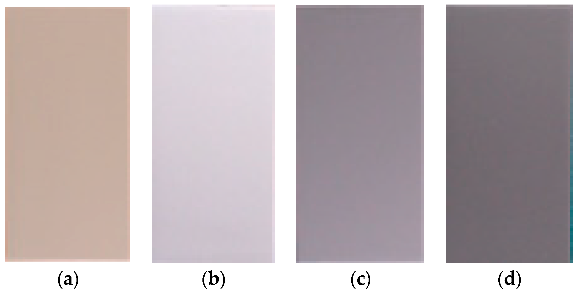
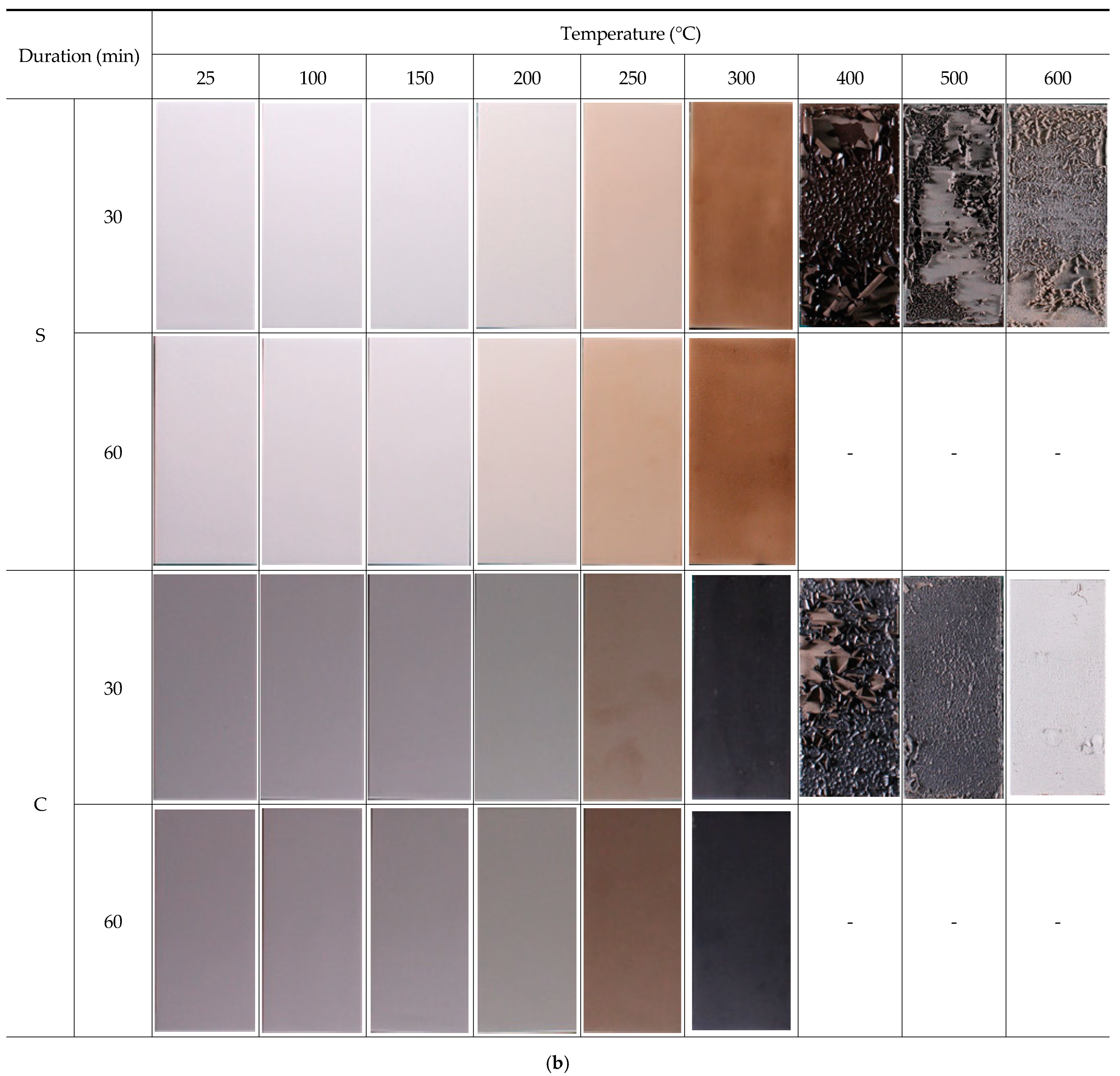
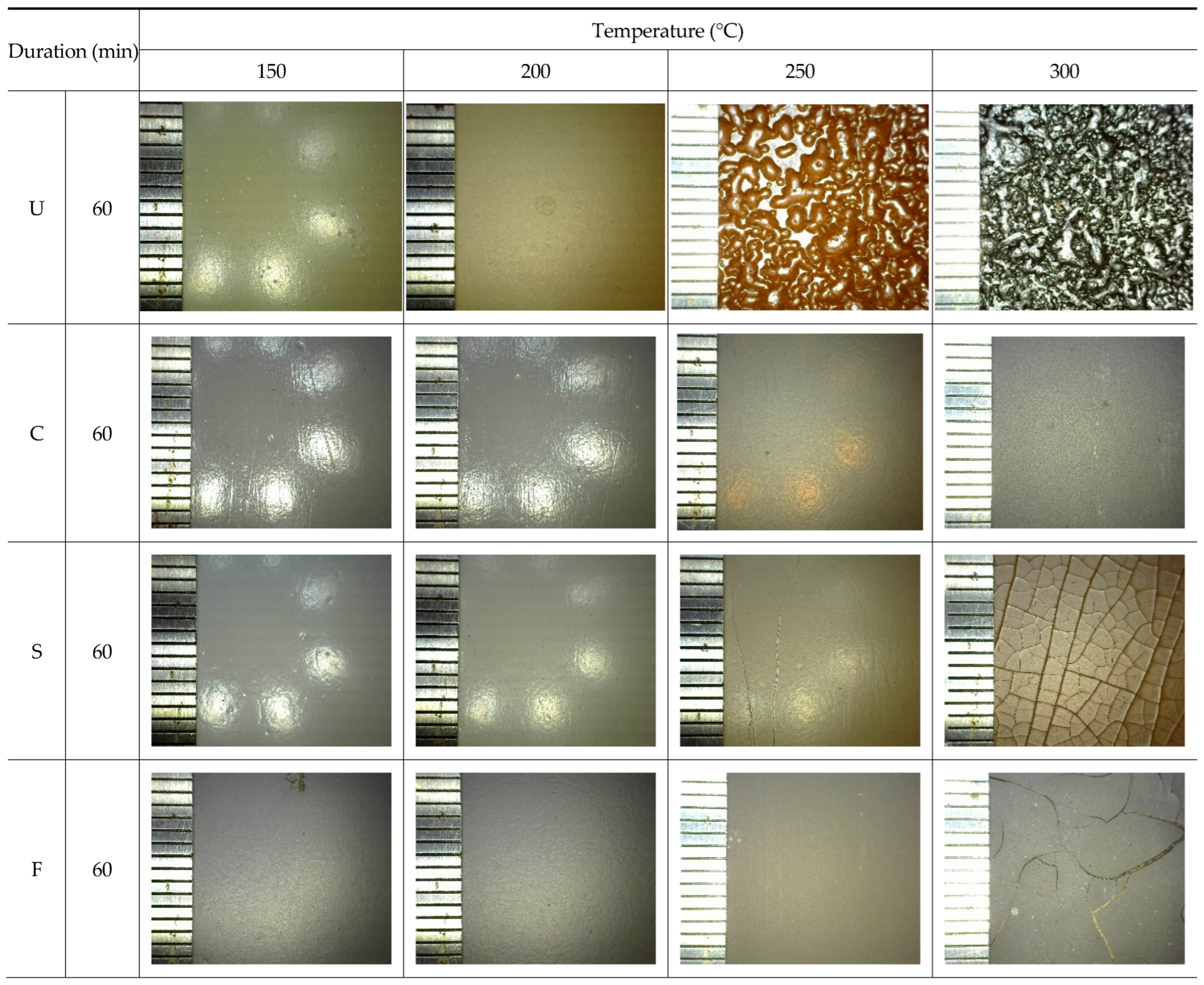
3.1. Visual Inspection (Discoloration, Delamination, Blistering, and Cracking)

The changes in the surfaces of the representative specimens, with varying temperatures and durations, are shown in Figure 3. For the U and F specimens, discoloration was observed at 200 °C, which was more distinct than at 250 °C, followed by blackening at 300 °C and whitening at 400 °C. Further, for U, the first signs of the paint film blistering were found across the entire surface at 250 °C. At 300 °C, increased levels of paint film blistering, cracking, and delamination were observed, followed by the delamination of the entire topcoat at 400 °C. However, the F specimens did not exhibit any paint film blistering at 250 °C.
For the U and C specimens, discoloration was observed at 250 °C, which became more distinct at 300 °C, followed by blackening at 400 °C and whitening at 600 °C. In addition, delamination of the entire topcoat was observed at 400 °C. Meanwhile, we observed no noticeable discoloration or paint film delamination across the four types of painting systems when heated for a duration of 30 or 60 min at each heating temperature.
In addition to the visual inspection, the surface was examined using a portable 20× magnifying glass for each system at heating temperatures of 150, 200, 250, and 300 °C and a heating duration of 60 min, as shown in Figure 4. For U, no noticeable change was observed up to 200 °C; however, at 250 °C, blistering across the entire surface was observed. For S, paint film cracking was observed at 250 °C, and an expanded net of cracks across the entire surface was observed at 300 °C. For F, no noticeable change was observed up to 250 °C; however, at 300 °C, paint film delamination across the entire surface was observed. For C, no noticeable change was observed up to 250 °C; however, at 300 °C, the first signs of the paint film cracking were detected.

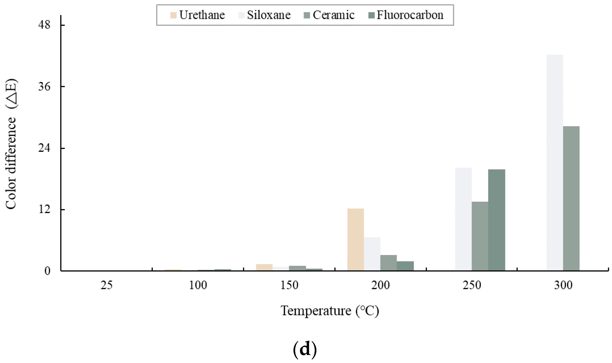
3.2. Color Differences of Paint Films

To quantitatively analyze the color change of the paint film with varying heating temperatures and durations, color differences were measured on the coated surfaces before and after the heating test. The specimens showing delamination, which prevents color measurement, were excluded. As the measured values did not vary considerably between the two heating durations, the mean value was obtained for the subsequent analyses.
At the same location on the surface of each specimen, L*, a*, and b* were measured before and after the heating test, and the color difference (ΔE*) was calculated using Equation (1):
Δ E * = Δ L * 2 + Δ a * 2 + Δ b * 2
Here, L* indicates the brightness, i.e., the relation between black (L* = 0) and white (L* = 100); a* indicates the relation between red (+) and green (−); and b* indicates the relation between yellow (+) and blue (−). The Δ symbol represents the variation between the pre-test and post-test states. The National Bureau of Standards (NBS) units of ΔE* were calculated using Equation (2) [22]:
NBS   units = Δ E * × 0.92
The variations in L*, a*, and b* with the increasing heating temperature are shown in Figure 5. As the heating temperature increased, blackening was first observed at 200 °C, followed by carbonization at 250 °C (Figure 5a). A prominent color change was observed at 200 °C with an increase in yellowness, as shown in Figure 5b,c. The color difference (ΔE*), as shown in Figure 5d and Table 7, was negligible until the heating temperature reached 150 °C but considerably increased at 200 °C, followed by a color change at 250 °C. A comparison of the color differences exhibited by each type of painted steel showed that the levels at 200 °C corresponded to the following order: F > C > S > U.

3.3. Visual Inspection of the Coated Surface and Estimation of the Temperature

Table 8 summarizes the results of the visual inspection and the color differences for varying heating temperatures for the four systems under study. Until the heating temperature reached 150 °C, paint film discoloration, blistering, and delamination were negligible, and between 150 and 200 °C, an insignificant level of discoloration was observed. Substantial discoloration, localized blistering, and delamination of the paint films were observed between 200 and 300 °C, followed by blackening and delamination across the entire paint film between 300 and 400 °C. Between 400 and 600 °C, whitening and delamination across the entire paint film was observed. Meanwhile, the variations according to the heating duration (30 min and 60 min) were indistinct and lacked a clear trend, indicating that the appearance of the coating is influenced by the fire temperature instead of the duration. Hence, as shown in Table 8, the fire temperature can be estimated via a visual inspection of the changes in the surface conditions regarding the discoloration and delamination of the four types of heavy-duty painting systems after being damaged by fire.

3.4. Evaluation for the Reuse of Coating Affected by Fire

To determine the possibility of repairing or reusing the four types of heavy-duty painting systems after fire damage, the gloss retention, pull-off adhesion, EIS, E-SEM, and FT-IR characteristics were analyzed before and after the heating test. As with the previous evaluation of the surface conditions, the specimens showing delamination were excluded. In addition, as no noticeable variation in the measurements was found across the four systems with respect to the heating duration (30 or 60 min) at each heating temperature, the mean values were applied for gloss retention, pull-off adhesion, and EIS, and the corresponding values for the heating duration of 60 min were applied for E-SEM and FT-IR.

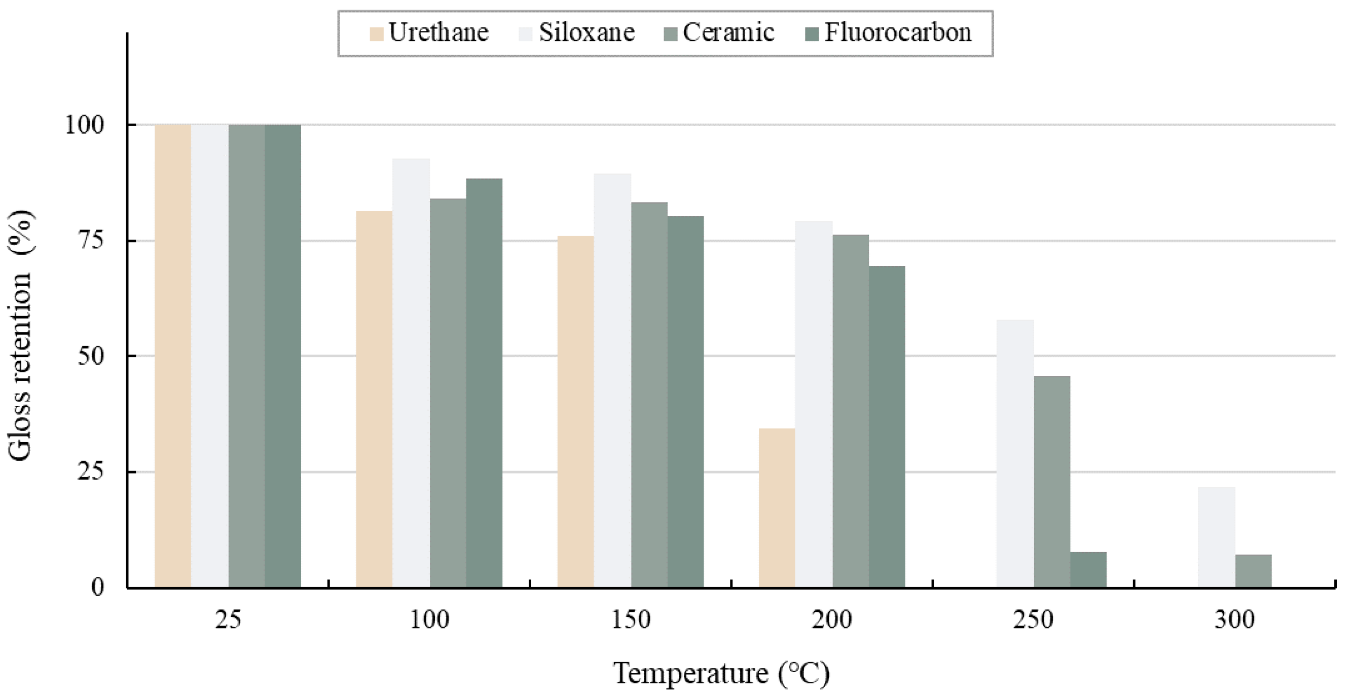
3.4.1. Gloss Retention

To quantitatively analyze the coated surface upon exposure to different heating temperatures and durations, the gloss retention of the coated surface was measured before and after the heating test. As performed previously, the specimens showing paint film delamination were excluded. Owing to the lack of major changes in the paint surface with varying heating durations, the mean value between the measurements at 30 and 60 min was applied.
Taking the ratio of gloss retention across the specimens before heating to that after heating as the gloss retention (%), the changes according to the heating temperature are shown in Figure 6. A decreasing trend was observed in the gloss retention as the heating temperature increased. A sudden decrease in the gloss retention was observed at 200 °C for U and at 250 °C for F, S, and C. In addition, the gloss retention for different heating temperatures across the four systems showed a decreasing trend of S > C > F > U.

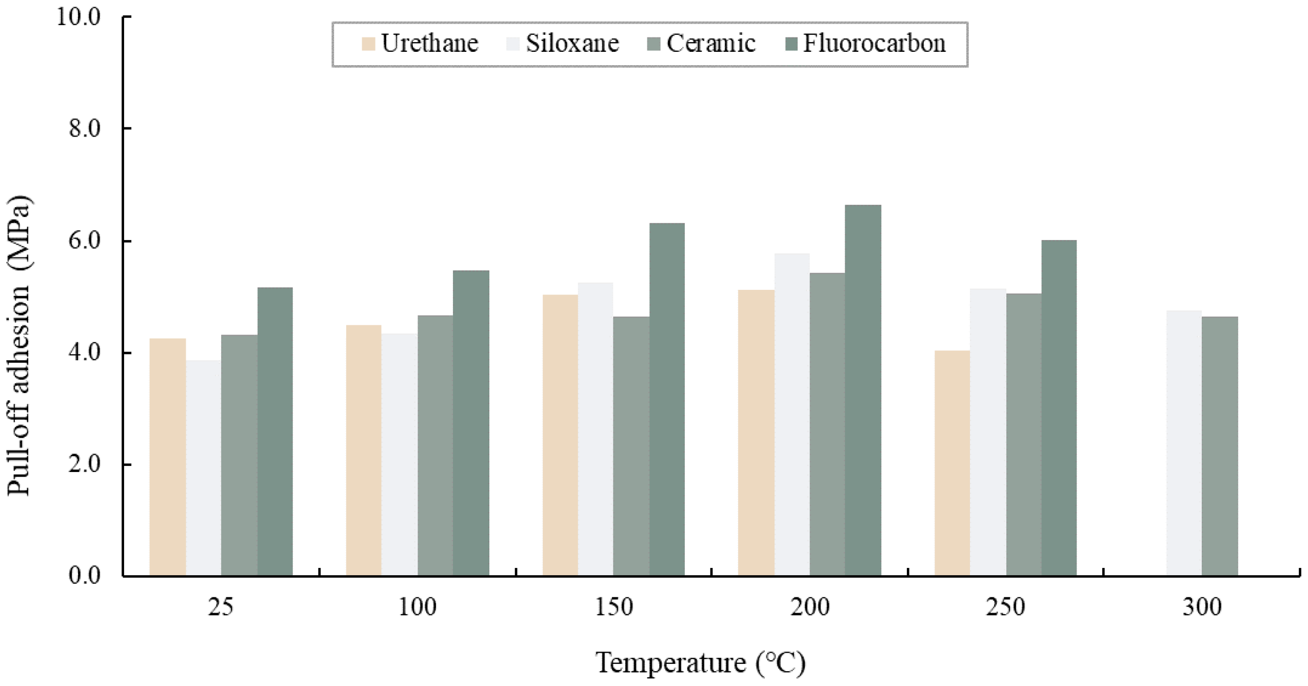
3.4.2. Pull-Off Adhesion

A pull-off test was used to measure the pull-off adhesion of the paint films before and after the heating test [23]. The pull-off adhesion was measured at two locations per specimen, and their mean is reported as the pull-off adhesion of each system. Specimens exhibiting blistering, cracking, or delamination of the topcoat were excluded.
As shown in Figure 7, the pull-off adhesion level initially increased with the rising heating temperature and then decreased. The temperature at which the increasing trend turned into a decreasing trend was 200 °C for U and 250 °C for S, C, and F. This may be due to an increase in the crosslink density owing to the additional hardening at certain temperatures, followed by heat-induced aging at higher temperatures [24,25]. The absence of paint film blistering, cracking, or delamination at temperatures ≤ 300 °C led to a decreased pull-off adhesion.

3.4.3. Electrochemical Impedance Spectroscopy (EIS)

Electrochemical impedance spectroscopy (EIS) is an electrochemical method that has been used for diverse purposes such as corrosion analysis and analyzing the adsorption properties of molecules. To objectively assess the anticorrosion performance of the coatings, their electrochemical properties were investigated, and a data analysis was carried out [26,27,28]. In general, an EIS value ≥ 108 Ω cm2 at low frequency indicates an outstanding anticorrosion performance; paint film aging starts below 106 Ω cm2, and the paint film loses its anticorrosion performance below 105 Ω cm2, wherein there is a high probability of corrosion underneath the paint film [27].
The EIS measurements before and after the heating tests are presented in Table 9. The EIS values measured for the four systems was >1010 Ω cm2 at 10 mHz; thus, they show no reduction in anticorrosion performance. For S, however, measurements could not be taken at 250 °C and above because of electrolyte leakage caused by the vertical cracking of the paint film.

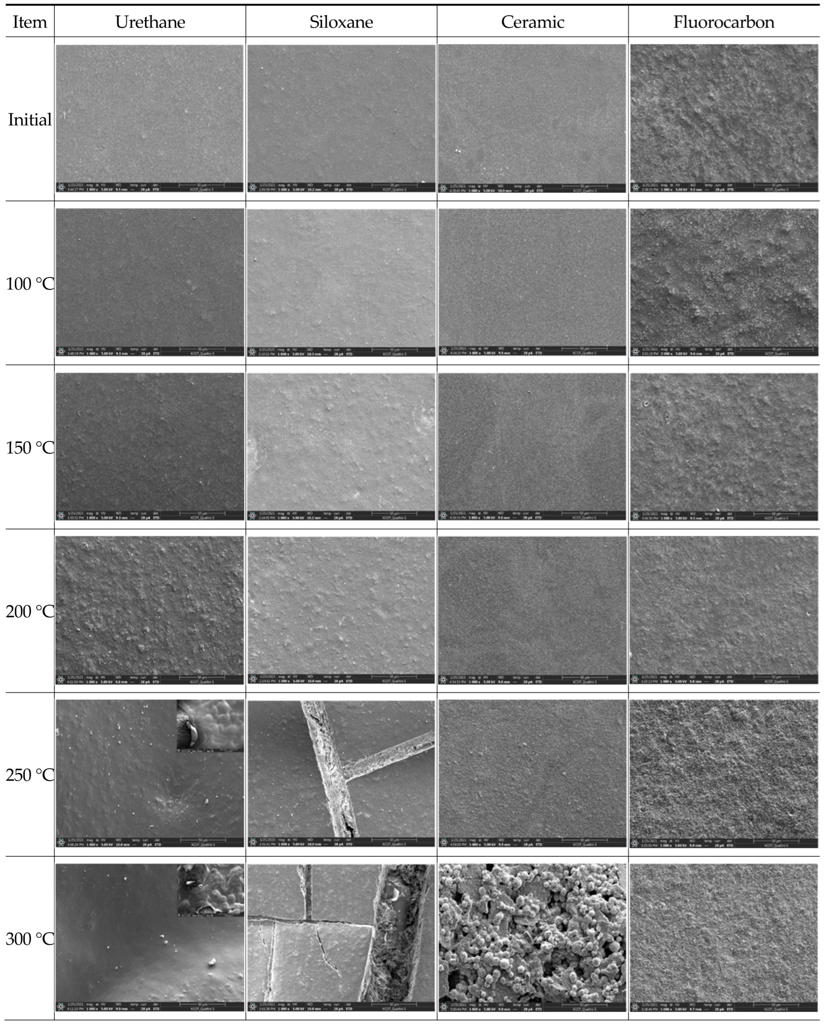
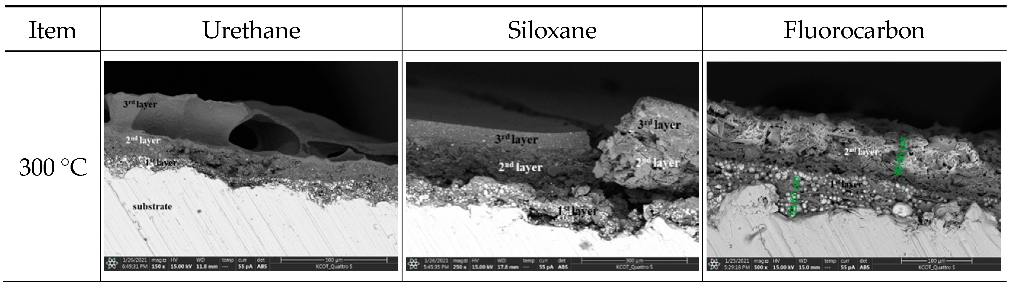
3.4.4. Surface Morphology Analysis through Scanning Electron Microscopy (E-SEM)

The results of the surface morphology and cross-section monitoring before and after the heating test via an E-SEM analysis are shown in Figure 8 and Figure 9. For U, the initial change in its surface morphology, including paint film blistering and delamination, was detected at 200 °C, with a subsequent linear increase in temperature. The cross-sections showed that the blistering and delamination phenomena were observed only on the topcoat. For S, no significant change was observed at 200 °C, but a significant change in its surface morphology was observed at 250 °C, i.e., vertical cracking was observed at 250 °C and above, which increased with the increasing temperature. The cross-sections showed that paint film cracking was observed only up to the intermediate layer. For C and F, the initial change in their surface morphology was detected at 250 °C, whereas the filler exposure and cohesion caused by the resin’s decomposition rapidly increased at 300 °C. The cross-sections at 300 °C for the F specimens showing paint film delamination confirmed the exposure of the intermediate layer. These surface changes are caused by thermal oxidation due to high temperatures and vary according to the paint type used [29,30].

3.4.5. Organic Structural Analysis

To monitor the changes in the organic structures of the four systems, FTIR spectroscopy was performed (Figure 10). For U, noticeable structural changes in C–O (1220 cm−1) and C=O (1686 cm−1) were first observed at 200 °C. For S, rapid structural changes in C=O (1728 cm−1) and Si–O–Si (1100 cm−1) were observed at 250 °C as the structural intensity of siloxane decreased. For C, rapid structural changes in C–O (1220 cm−1), C=O (1686 cm−1), and C–H (2859 cm−1) were observed at 250 °C. For F, rapid structural changes in C–H (2859 cm−1), C=O (1686 cm−1), and C–F2 (1110 cm−1) were observed at 250 °C [31]. The peak intensity decreased as a result of heat exposure-induced destructive changes in the polymer structure. It can be seen that C–O (ether bonds) and C=O (carbonyl bonds) bonds were reduced due to polymer degradation caused by chain scission [32,33].

4. Potential Applications of the Test Results

In fire accidents, the mechanical properties of steel materials are influenced by the fire’s temperature and duration, for which various empirical studies have been conducted. For example, the Guideline of Steel Structure Fireproof Design by the Architectural Institute of Japan [34] states that the highest temperatures for which the tensile strength is maintained for rolled steel materials in steel structures (SS400) and those in welded structures (SM490) are 300 and 250 °C, respectively. Hence, the tensile strength of the steel materials was retained even at temperatures up to 300 and 250 °C, whereas a rapid decrease was observed after 400 °C. In addition, for the high-tension bolts F10T and S10T, the tensile strength at room temperature was maintained until 250 °C, whereas a rapid decrease was observed after 300 °C. Thus, the rolled steel materials in the steel structures and high-tension bolts retain the same tensile strength at room temperature for up to 250–300 °C.
In the case of a fire on a steel bridge, the estimation of an elevated temperature during a visual inspection after the fire’s control can help decide whether services on the bridge can be resumed. The heating temperature can be estimated based on the changes in the surface of the steel material’s coating, i.e., discoloration and delamination. The four systems considered in this study exhibited carbonization and delamination at heating temperatures of 300–400 °C. This indicates a potential reduction in the tensile strength of the steel materials when the coated surface undergoes carbonization after a fire; thus, traffic should be stopped, and a thorough safety assessment should be performed to examine the structural safety and use performance of the steel bridge. On the contrary, when blackening or delamination did not occur, the tensile strength of the steel materials was maintained at fire temperatures < 300 °C. At temperatures of 200–250 °C or below, where favorable surface conditions without cracking or delamination appear, it is safe to assume that the anticorrosion performance of the coating is intact, allowing for the reuse of the coating after the surface has been cleaned. Table 10 and Figure 11 may be useful in thermal impact analyses in relation to fire accidents as well as various maintenance works for steel bridges (welding, asphalt pavement, etc.) that require high temperatures.

5. Conclusions

The present investigation examined the use of the visual inspection of steel bridge coatings after a fire to estimate the fire temperature and determine the threshold temperature that enables the reuse of the coating. Four types of heavy-duty painting systems (urethane, siloxane, ceramic, and fluorocarbon) of the Korean Construction Specification (KCS 14 31 40) were tested using an electric furnace at heating temperatures of 100, 150, 200, 250, 300, 400, 500, and 600 °C for 30 and 60 min. The results of the heating tests are summarized as follows:
(1)
As the heating temperature increased from 100 to 600 °C, a noticeable discoloration occurred at 200–300 °C, followed by blackening at 300–400 °C and whitening at 400–600 °C. At 200–300 °C, localized paint film cracking and delamination were observed, while all the topcoats showed delamination at 300–600 °C.
(2)
As the heating temperature increased from 100 to 200 °C, a trend of an increase in the pull-off adhesion of the paint film by 20%–30% was followed by a slight drop at 200–250 °C. In addition, a notable decrease in pull-off adhesion did not occur when the paint film showed no blistering or delamination.
(3)
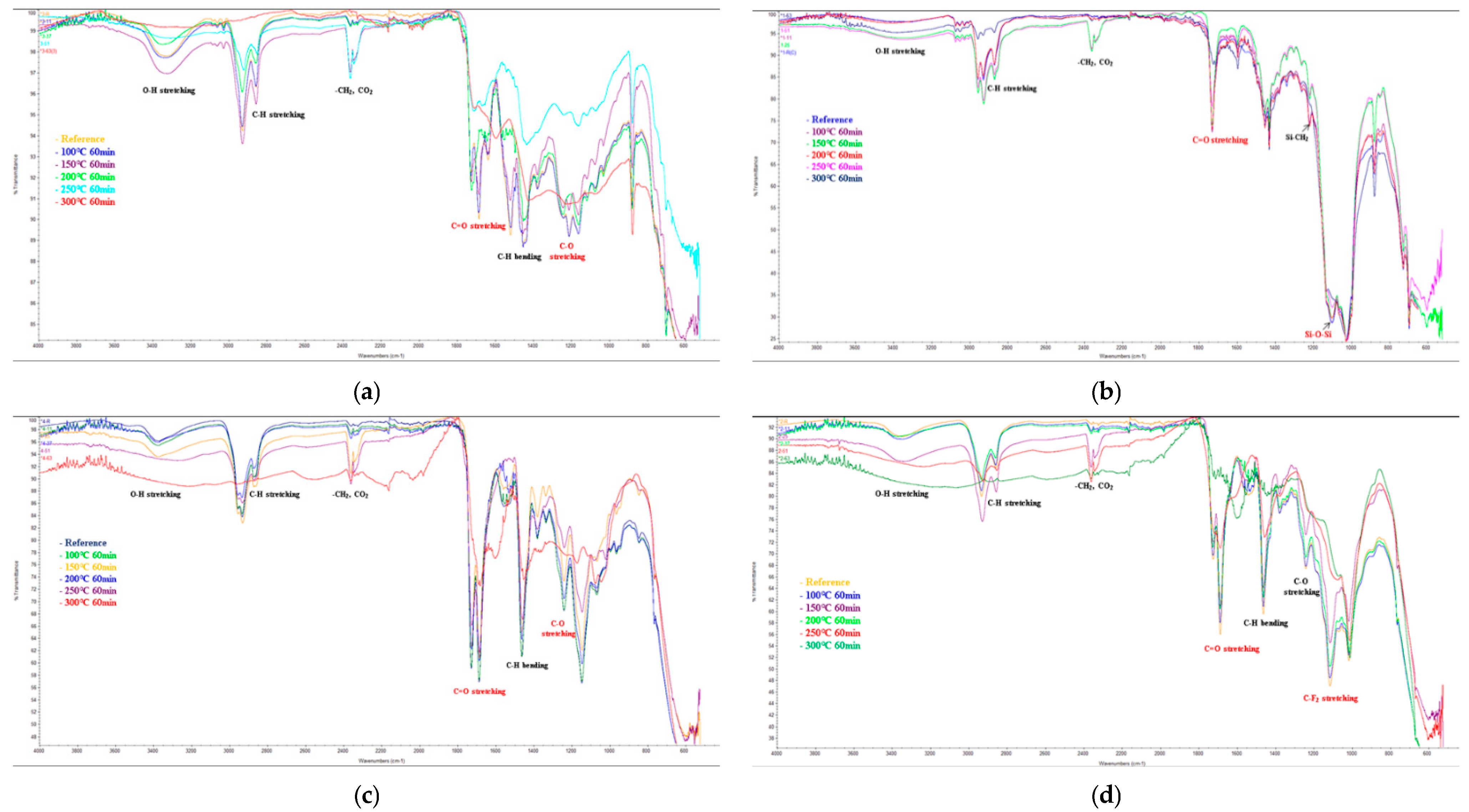
The EIS, E-SEM, and FT-IR analyses to assess the anticorrosion performance of the four painting systems showed that the temperature at which fire damage occurred was 200 °C for urethane and 250 °C for siloxane, ceramic, and fluorocarbon. The anticorrosion performance was retained until the heating temperature of 200 °C.
(4)
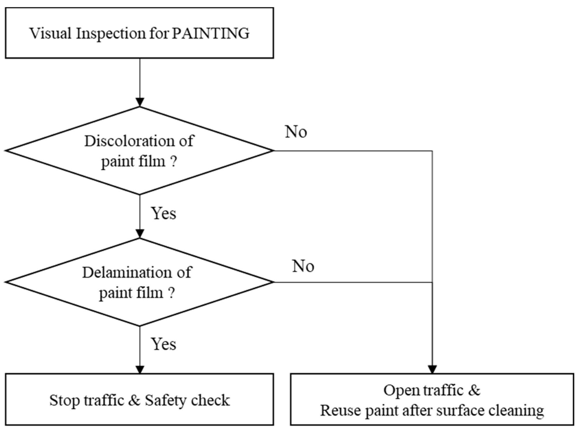
The temperature-dependent changes in the surface conditions for the paint systems under study were confirmed to constitute a useful indicator in the visual inspection used to estimate the fire temperature and its range for a steel bridge. The visual inspection method (Figure 3) and the levels of discoloration and delamination of each system (Table 9) can allow for rapid responses to steel bridge fires with respect to deciding whether to stop or re-open the bridge to traffic after the fire’s control and determining the scope and methods of the repair and maintenance of the steel bridge.

Author Contributions

Conceptualization, I.-T.K.; formal analysis, K.-H.C. and A.-S.S.; data curation, K.-H.C. and Y.-S.J.; writing—original draft preparation, K.-H.C.; writing—review and editing, I.-T.K., K.-H.C., Y.-S.J. and A.-S.S.; funding acquisition, I.-T.K. All authors have read and agreed to the published version of the manuscript.

Funding

This work was supported by the National Research Foundation of Korea (NRF) grant funded by the Korean government (MSIP) (No. NRF-2020R1A2B5B01097751).

Institutional Review Board Statement

Not applicable.

Informed Consent Statement

Not applicable.

Data Availability Statement

Not applicable.

Conflicts of Interest

The authors declare no conflict of interest.

References

  1. Kodur, V.; Gu, L.; Garlock, M.E. Review and assessment of fire hazard in bridge. J. Transport. Res. Board 2010, 2172, 23–29. [Google Scholar] [CrossRef]
  2. Garlock, M.; Paya-Zaforteza, I.; Kodur, V.; Gu, L. Fire hazard in bridges: Review, assessment and repair strategies. Eng. Struct. 2012, 35, 89–98. [Google Scholar] [CrossRef]
  3. Shim, J.W.; Shin, Y.H. Fire Damage Evaluation on Fire Source under the Bridge. J. Korean Soc. Steel Construct. 2010, 22, 75–78. (In Korean) [Google Scholar]
  4. Ohyama, O.; Imagawa, Y.; Kurita, A. Damage examples of bridge caused by fire. Bridge Found. Eng. 2008, 42, 35–39. (In Japanese) [Google Scholar]
  5. Hong, S.Y.; Jeong, S.Y.; Baek, S.G.; Choi, Y.H. The social cost of a fire under Bucheon Viaduct of Seoul ring expressway. Mag. Transp. Technol. Policy 2011, 8, 83–87. (In Korean) [Google Scholar]
  6. Kim, S.H.; Chung, K.S.; Choi, S.M. Residual strength of steel and composite structures damaged by fire. Mag. Korean Soc. Steel Construct. 2010, 26, 34–39. (In Korean) [Google Scholar]
  7. Kim, Y.S.; Choi, B.J. Experimental study on the fire resistance of steel-reinforced concrete column in fire according to load ratio. J. Korean Soc. Steel Construct. 2019, 31, 459–470. (In Korean) [Google Scholar] [CrossRef]
  8. Kim, S.Y.; Lee, J.S.; Lee, H.D.; Shin, K.J. Collapse behavior of PEB building through fire test. J. Korean Soc. Steel Construct. 2020, 32, 1–10. (In Korean) [Google Scholar] [CrossRef]
  9. Lee, S.Y.; Kang, S.D.; Choi, S.K.; Kim, M.H.; Kim, S.D. Experimental study on the fire resistance of the iTECH composite beam. J. Korean Soc. Steel Construct. 2006, 18, 643–653. (In Korean) [Google Scholar]
  10. Short, N.R.; Purkiss, J.A.; Guise, S.E. Assessment of fire damaged concrete using colour image analysis. Construct. Build. Mater. 2001, 16, 9–15. [Google Scholar] [CrossRef]
  11. Lee, J.W.; Choi, K.H.; Hong, K.P. Color and material property changes in concrete exposed to high temperatures. J. Asian Archit. Build. Eng. Build. Mater. 2009, 8, 175–182. [Google Scholar] [CrossRef] [Green Version]
  12. Lempereur, C.; Andral, R.; Prudhomme, J.Y. Surface temperature measurement on engine components by means of irreversible thermal coating. Meas. Sci. Technol. 2008, 19, 105501–105512. [Google Scholar] [CrossRef]
  13. Pelvich, C.W.; Foulk, D.L.; Polec, T.W. Method of Sensing High Surface Temperature in an Aircraft. Patent EP1959246 A2, 19 June 2008. [Google Scholar]
  14. Belykh, A.V.; Efremov, A.M.; Mikhailov, M.D. Thermochromic Material. European Patent EP1405890 B1, 17 October 2012. [Google Scholar]
  15. Lataste, E.; Demourgues, A.; Salmi, J.; Naporea, C.; Gaudon, M. Thermochromic behaviour (400 < T °C < 1200 °C) of barium carbonate/binary metal oxide mixtures. Dyes Pigm. 2011, 91, 396–403. [Google Scholar]
  16. KCS 14 31 40:2019; Korean Construction Specification. Paint. Ministry of Land, Infrastructure and Transport: Sejong, Korea, 2019. (In Korean)
  17. KS M ISO 8501-1; Preparation of Steel Substrates before Application of Paints and Related Products—Visual Assessment of Surface Cleanliness. Korean Agency for Technology and Standards: Chungcheongbuk-do, Korea, 2021. (In Korean)
  18. ANSI/AISC 360-16; Specification for Structural Steel Buildings. American Institute of Steel Construction: Chicago, IL, USA, 2016; pp. 222–226.
  19. Korea Expressway Corporation. Exploring of Fire Resistance Design of Bridge Substructure and Underneath Structure; Korea Expressway Corporation: Gimcheon, Korea, 2013. [Google Scholar]
  20. National Fire Agency. Fire Statistical Yearbook; National Fire Agency: Sejong, Korea, 2019. (In Korean)
  21. Ministry of Land, Infrastructure and Transport, and Korea Authority of Land & Infrastructure Safety. Detailed Guideline for Facility Safety Management and Maintenance (Performance Assessment); Korea Authority of Land & Infrastructure Safety: Jinju, Korea, 2018.
  22. Mohammed, Q.A.Q.; Salman, S.B. Color change of direct resin-based composites after bleaching: An in vitro study. King Saud Univ. J. Dent. Sci. 2011, 2, 23–27. [Google Scholar]
  23. KS M ISO 4624:2016; Paint and Varnishes-Pull off Test for Adhesion. Korean Agency for Technology and Standards: Chungcheongbuk-do, Korea, 2016. (In Korean)
  24. Lee, L.H. Adhesive Bonding; Springer: New York, NY, USA, 1991; p. 260. [Google Scholar]
  25. Knudsen, O.O.; Forsgren, A. Corrosion Control through Organic Coatings; CRC Press: Boca Raton, FL, USA, 2017; p. 141. [Google Scholar]
  26. Amirudin, A.; Thierry, D. Application of electrochemical impedance spectroscopy to study the degradation of polymer-coated metals. Prog. Org. Coat. 1995, 26, 1–28. [Google Scholar] [CrossRef]
  27. Lee, C.Y.; Lee, S.H.; Park, J.H. Evaluation of deterioration of epoxy primer for steel bridge coating using image processing and electrochemical impedance spectroscopy. J. Corros. Sci. Technol. 2009, 8, 53–61. [Google Scholar]
  28. Barsoukov, E.; Macdonald, J.R. Impedance Spectroscopy: Theory, Experiment, and Applications, 2nd ed.; John Wiley & Sons, Inc.: Hoboken, NJ, USA, 2005. [Google Scholar]
  29. Liu, J.; Tang, J.; Wang, X.; Wu, D. Synthesis, characterization and curing properties of a novel cyclolinear phosphazene-based epoxy resin for halogen-free flame retardancy and high performance. RSC Adv. 2012, 2, 5789–5799. [Google Scholar] [CrossRef]
  30. Awaja, F.; Zhang, S.; Tripathi, M.; Nikiforov, A.; Pugno, N. Cracks, microcracks and fracture in polymer structures. Prog. Mater. Sci. 2016, 83, 536–573. [Google Scholar] [CrossRef]
  31. Sigma Aldrich, IR Spectrum Table & Chart. Available online: https://www.sigmaaldrich.com/KR/ko/technical-documents/technical-article/analytical-chemistry/photometry-and-reflectometry/ir-spectrum-table (accessed on 20 May 2022).
  32. Doblies, A.; Boll, B.; Fiedler, B. Prediction of thermal exposure and mechanical behavior of epoxy resin using artificial neural networks and fourier transform infrared spectroscopy. Polymers 2019, 11, 363. [Google Scholar] [CrossRef] [PubMed] [Green Version]
  33. Lee, J.S. Thermal decomposition of fluoropolymers and firing characteristics of priming compositions with fluoropolymers. J. Appl. Polym. Sci. 2005, 97, 2054–2059. [Google Scholar] [CrossRef]
  34. Architectural Institute of Japan. Recommendation for Fire Resistant Design of Steel Structures; Maruzen: Hiroshima, Japan, 2008. (In Japanese) [Google Scholar]
Figure 1. Painted steel specimens: (a) Urethane (U); (b) Siloxane (S); (c) Ceramic (C); (d) Fluorocarbon (F).
Coatings 12 01697 g001
Figure 2. Experimental test setup for the electric furnace heating test.
Coatings 12 01697 g002
Figure 3. Surface conditions according to heating temperature and duration: (a) Urethane (U) and Fluorocarbon (F); (b) Siloxane (S) and Ceramic (C).
Coatings 12 01697 g003aCoatings 12 01697 g003b
Figure 4. Magnified surface conditions (20×).
Coatings 12 01697 g004
Figure 5. Color change according to heating temperature: (a) change in lightness (ΔL*); (b) change in red/green value (Δa*); (c) change in the blue/yellow value (Δb*); (d) color difference (ΔE*).
Coatings 12 01697 g005aCoatings 12 01697 g005b
Figure 6. Gloss retention according to heating temperature.
Coatings 12 01697 g006
Figure 7. Pull-off adhesion according to heating temperature.
Coatings 12 01697 g007
Figure 8. Magnified surface conditions (1000×).
Coatings 12 01697 g008
Figure 9. Magnified X-section conditions (~150–500×).
Coatings 12 01697 g009
Figure 10. Fourier-transform infrared spectra under varying conditions of temperature from 100 °C to 300 °C: (a) urethane; (b) siloxane; (c) ceramic; (d) fluorocarbon.
Coatings 12 01697 g010
Figure 11. A flow diagram depicting the rapid response to a steel bridge fire.
Coatings 12 01697 g011
Table 1. Color changes in concrete at specified range of temperature, T.
Range of Temperature (°C)ColorAppearanceCondition
T < 300NormalNormalNormal
300 ≤ T < 600Pink or redSurface crazing, cracking, and aggregate pop outsSound, but strength may be reduced
600 ≤ T < 900Whitish greySpalling, exposed of steel reinforcement and powdered existenceWeak
T ≥ 1000BuffExtreme spallingExtreme/severe
Table 2. Color changes in steel at specified range of temperature, T.
Range of Temperature (°C)ColorAppearanceCondition
T < 600Little changeNo visible damage or distortion may occurWeak
T > 600Little changeLarge deflection or localized distortionExtreme/severe
Table 3. Material properties of the SS275 steel.
MaterialYield Strength [MPa]Tensile Strength [MPa]Elongation at Failure [%]
SS27534241640
Table 4. Chemical composition of the SS275 steel (Unit: wt%).
MaterialCSiMnPS
SS2750.1500.1000.3900.0140.007
Table 5. Painting system of specimens.
Painting SystemSymbolColorCoating Layer (µm)Paint Film Thickness
(µm)
1st2nd3rd
UrethaneUBoneInorganic Zinc
(75)
High-solid epoxy
(80)
Urethane
(60)
215
SiloxaneSAnti-flash WhiteInorganic Zinc
(75)
High-solid epoxy
(80)
Polysiloxane
(60)
215
CeramicCSpanish GrayInorganic Zinc
(75)
Ceramic protective paint
(75)
Ceramic urethane
(75)
225
FluorocarbonFDolphin GrayInorganic Zinc
(75)
High-solid epoxy
(100)
Fluorocarbon
(50)
225
Table 6. Total number of test specimens.
Temperature
(°C)
Duration Time (min)
3060
USCFUSCF
Initial2222-
10066667777
15066667777
20066667777
25066667777
30066667777
4001111-
5001111-
6001111-
Table 7. National Bureau of Standards (NBS) ratings.
N.B.S UnitSensitive Expression of Color Difference
0.0–0.5Trace (Extremely slight change)
0.5–1.5Slight (Slight change)
1.5–3.0Noticeable (Perceivable change)
3.0–6.0Appreciable (Marked change)
6.0–12.0Much (Extremely marked change)
>12.0Very much (Change to another color)
Table 8. Relationship between temperature and surface condition change of heavy-duty-paint-coated steel.
Temperature (°C)DiscolorationPaint Film Condition
~150Extremely slight changeExtremely slight change
150–200Slight change
200–300Marked changeBlistering, Partial delamination
300–400Blackening (Changes to black) Full delamination
400–600Whitening (Changes to white)
Table 9. Electrochemical Impedance Spectroscopy (EIS) according to heating temperature.
ItemImpedance (Ω cm2, 0.01 Hz)
UrethaneSiloxaneCeramicFluorocarbon
100 °C2.00 × 10101.23 × 10102.73 × 10102.36 × 1010
150 °C2.79 × 10102.29 × 10103.26 × 10102.49 × 1010
200 °C2.41 × 10102.63 × 10103.17 × 10103.42 × 1010
250 °C--3.01 × 10102.25 × 1010
300 °C--2.34 × 10¹⁰-
Table 10. Analysis of fire damage through visual inspection of coating’s surface conditions.
AppearanceTemperature, T (°C)Steel MemberPainting Systems
Extremely slight changeT ≤ 150OK as isOK as is
Slight change (discoloration)150 < T ≤ 200OK as isOK as is
Blistering
Partial delamination
200 < T ≤ 300OK as isRepair
Blackening/Whitening
Full delamination
300 < T ≤ 600Reinforcement with new members or heating straightening requiredRepair
Publisher’s Note: MDPI stays neutral with regard to jurisdictional claims in published maps and institutional affiliations.

