1. Introduction
Plasma spraying takes plasma arc as the heat source, heats and accelerates particles to a molten state in a very short time, impacts the substrate surface, and forms a flattening grains coating layer by rapid cooling, solidification, and deposition [
1,
2]. Plasma spraying has the characteristics of a convenient process, high reliability, and a diversified material system [
3]. The process effectively improves the wear resistance of the material surface without changing the substrate structure, thus improving the comprehensive service performance of parts, which is of great significance to prolong the service life of moving parts, such as engineering machinery and equipment [
4,
5]. For example, as one of the important parts of the engine, the cylinder liner is affected by the high temperature and high pressure produced by the fuel oil during operation and, at the same time, sees the reciprocating friction between the piston ring and the piston skirt, and constantly bears the alternating load [
6]. With an increasing emphasis on environmental protection, it is required to reduce the emissions of the automobile engine. Surface strengthening treatment of the cylinder inner wall to improve the wear resistance of the cylinder liner is of great significance in extending the service life of the engine and reducing fuel consumption [
7].
An Fe-based coating alloy has a low cost, good mechanical properties, and excellent compactness, and is widely used in bearings, plungers, and other aspects [
8,
9]. The FeNiCrBSi alloy powder was prepared by the gas atomization method, and the wear-resistant coating was prepared on the surface of aluminum alloy by a high-velocity oxygen fuel process. When the gas atomization temperature and pressure were 1500 °C and 3.5 MPa, respectively, the prepared powder had a smooth surface and a regular shape, the porosity of wear-resistant coating was 1.23%, and the hardness was up to 635 HV
0.3 [
10]. FeCrMnCNi alloy coating was prepared by plasma spraying. The hard phase in the coating was mainly cementite, and a good mechanical bond is found between the coating and the matrix. The coating surface was easy to undergo plastic deformation, thus forming grooves, which belonged to typical abrasive wear [
11]. The wear resistance of the atmospheric plasma-sprayed FeCrBSi coating is much better than that of a 316L stainless steel coating, and after heat treatment at 700 °C, the wear resistance of the coating reaches the best, which is (0.481 ± 0.023) × 10
−5 mm
3/Nm [
12]. The contact fatigue failure mechanism of supersonic plasma-sprayed iron-based coatings has three typical failure modes [
13]. The sliding rate has a significant effect on the rolling contact fatigue performance of the iron-based alloy coating, and the failure life of the coating decreases continuously with the increase of the sliding rate [
14].
Particles are converted to a molten or highly plastic state in plasma coatings, which are widely used for these reasons, but there are substantial disadvantages in such coatings because of the high porosity and poor adhesion to the substrate [
15]. The microstructure and properties of plasma-sprayed coatings are mainly determined by the raw conditions of the substrate surface and the characteristics of the molten particles [
16,
17,
18]. The former mainly refers to the surface roughness of the substrate, temperature, etc., while the latter includes molten particle droplet size, temperature, speed, physical and chemical state, etc. The main factors affecting the characteristics of molten particles are spraying process parameters, including spraying distance, voltage, current, main gas flow, secondary gas flow, powder feeding rate, carrier gas flow, etc., which are the key points of research on various plasma spraying materials [
19,
20]. The research on the effect of plasma spraying parameters on the microstructure and properties of Fe-based coatings is helpful to promote the application of the Fe-based wear-resistant coatings.
In this paper, a kind of wear-resistant Fe-Cr-B-C alloy coating was prepared on stainless steel substrate by plasma spraying. The main factors of plasma spraying were working current, main gas flow, secondary gas flow, and spraying distance. The effects of these factors on the hardness and bonding strength of the coating were investigated, and the plasma spraying process parameters were optimized. Moreover, the friction and wear properties of the Fe-Cr-B-C alloy coating prepared by plasma spraying were compared with those of 304 stainless steel.
2. Preparation and Characterization of Material
The Fe-Cr-B-C alloy powder for spraying was prepared by the gas atomization method. The main element composition of the alloy powder was 12.0% Cr, 2.4% B, and 0.5% C (mass percent, wt.%). Two types of 304 stainless steel, 30 mm × 10 mm × 3 mm in strip shape and 25.4 mm in diameter × 10 mm in height in a cylinder shape, were used as the substrate material of the coating. Before spraying, the substrate material was cleaned with acetone with an ultrasonic wave to remove the oil stain on the surface. Then, white corundum powder with −24+60 meshes was adopted for sand blasting treatment. The sand blasting machine was a pressed-in sand blasting machine (model PS1010AP, Ciamite New Alloy Material (Changzhou) Co., Ltd., Guangzhou, China), and the sand blasting air pressure was 0.6~0.8 Mpa. Atmospheric plasma spraying equipment was a BSX-80 spraying system from Xiamen Baishunxing Automation Co., Ltd. (Xiamen, China), with a spray gun model of F4, argon as the main gas and carrier gas, and helium as the secondary gas. The main process parameters of atmospheric plasma spraying (current, main gas flow, secondary gas flow, and spraying distance) were selected. The factors and levels and the corresponding abbreviations of specific parameters of the orthogonal experiment were shown in
Table 1, and nine groups of coatings were obtained in total. The powder feeding rate was 40 g/min, the moving distance of the spray gun was 500 mm/s, and the step distance was 2 mm. During spraying, compressed air with a flow rate of 6 L/min was used as cooling air to cool down the sample to prevent the substrate from overheating.
The microhardness of the coating was measured with a Vickers hardness tester (HVS-1000, LaizhouHuayin, Laizhou, China) under a test load of 100 g for 15 s. The Vickers hardness of each group was tested at different positions 10 times and their average value was taken for analysis. The bonding strength test samples were prepared by the gluing method, and the bonding strength of the coating was measured by an electronic universal testing machine (WDW-100Y, Jinan Liantai, Jinan, China). The tensile speed was 0.5 mm/min, and the maximum bonding strength of the tensile samples at break was recorded. There were three samples in each group, and their average value was taken for analysis. The wear resistance of the samples was tested by pin-on-disc friction and wear tester (SFT-2M, Zhongke Kaihua, Shenyang, China), and the wear track was measured by the probe of the equipment. The wear load was 10 N, the ball was a 6 mm Si4N3 ball, the wear radius was 3 mm, and the wear time was 60 mins. The phases of the powder and coating were determined by an X-ray diffractometer (XRD, CuKα, D8 Advanced, Bruker, Karlsruhe, Germany) at a test voltage of 40 kV, a current of 40mA, a scanning range of 20~80°, and a scanning speed of 6°/min. The apparent density and flowability of the Fe-Cr-B-C powder were measured by a Hall flowmeter, and the average value was obtained by measuring it three times. A scanning electron microscopy (SEM, JSM-6390LA, JEOL, Tokyo, Japan) was used to observe the microstructure of the powder and coating. The coating composition was analyzed by an energy-dispersive spectrometer.
3. Results and Analysis
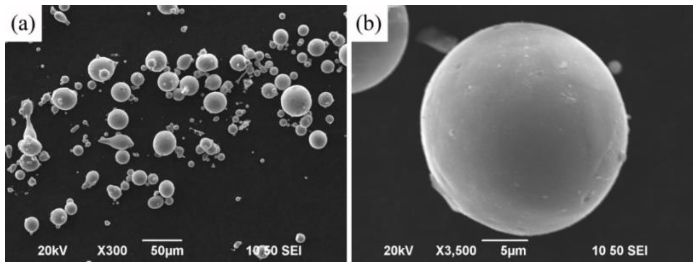
Figure 1 shows the morphology of the Fe-Cr-B-C powder. It can be seen from
Figure 1 that the Fe-Cr-B-C alloy powder obtained by gas atomization is regular spherical, which meets the service requirements of plasma spraying. The atomization powder consists of powder particles with two types of morphology. The first type of powder is coarser particles of regular spherical powder with a smooth surface. As can be seen in
Figure 1b, these powders are substantially free of cracks and have a relatively high density. The second type of powder is smaller irregularly shaped particles, which account for a smaller proportion. The particle size of that powder ranges from 15 μm to 45 μm, and the result of the flow property of the powder is 26 s/50 g. The apparent density of the powder is 4.05 g/cm
3. These basic characteristics of the powder are beneficial to the flow and filling of the powder in the spraying process and meet the service requirements of atmospheric plasma spraying. The particles could acquire a good melting state by spraying when heated fully [
21].
Atmospheric plasma spraying was carried out according to the orthogonal design parameters listed in
Table 1. The physical meaning and calculation methods of K1, K2, K3, and range D of each factor are shown in the literature [
22].
The bonding strength and microhardness of the coating corresponding to each coating process were also listed in
Table 1. The result of bonding strength and microhardness were analyzed by a range method. The range and variance of each factor were obtained, which were also listed in
Table 1. Among them, K is the average result of each factor at different levels, reflecting the influence of different levels of each factor on the results. The range D of the results of a certain factor at different levels reflects the influence degree of the level change of the factor on the results. The greater the variance, the more important the factor is, otherwise, the factor is a secondary factor [
22].
To more clearly reflect the influence of each spraying process parameter on the coating bonding strength, the influence of the four parameters on the coating bonding strength and microhardness was plotted in
Figure 2. It can be seen in
Table 1 and
Figure 2 that the secondary gas flow has the greatest influence on the bonding strength of the coating, while the main gas flow has the smallest influence on the bonding strength. The descending order of the influence of the four factors on the bonding strength is as follows: the secondary gas flow, the spraying current, the spraying distance, and the main gas flow.
It can be seen in
Figure 2b that the microhardness of the coating obtained by different processes is relatively high, the overall difference is not large, and the microhardness of the coating is in the range of 820~860 HV
0.1. The descending order of influencing factors on the microhardness of the Fe-Cr-B-C coating prepared by plasma spraying is as follows: spraying distance, secondary gas flow, main gas flow, and current. That is, spraying distance has the greatest influence on the microhardness of the coating. Based on the results of microhardness and bonding strength of the Fe-Cr-B-C coating, the optimal spraying parameters are as follows: a spray current of 500 A, a main gas flow of 40 L/min, a secondary gas flow of 17 L/min, and a spraying distance of 100 mm. The bonding strength and microhardness of the FeCrBC alloy coating obtained by this optimized process are 69.8 Mpa and 852.1 HV
0.1, respectively.
Figure 3 is a friction coefficient curve of the Fe-Cr-B-C alloy coating and the 304 stainless steel substrate obtained by using the optimized process.
As can be seen in
Figure 3, the initial friction coefficient of the 304 stainless steel sample is about 0.6, the friction coefficient increases slightly during wear, and the final friction coefficient is basically unchanged, about 0.62. This is because in the process of wear, with the increase of wear, the contact area between the friction pair and the sample increases, so the friction coefficient increases. The initial friction coefficient of the Fe-Cr-B-C alloy coating is about 0.85. After a short running-in period of 5 min, the friction coefficient decreases rapidly. After 10 min, the friction coefficient of the Fe-Cr-B-C coating tends to be stable and finally stabilizes at 0.5.
Table 2 shows the results of the friction and wear test of the Fe-Cr-B-C coatings against the 304 stainless steel. It can be found that the depth, width, and volume of the wear track of the coating sample are significantly reduced compared with those of the 304 stainless steel substrate. The wear rate of the coated sample is 0.62 × 10
−5 mm
3/Nm, which is only 51% of that of the 304 stainless steel substrate sample.
Figure 4 shows XRD patterns of the Fe-Cr-B-C powder and coating. It can be seen in
Figure 4 that the matrix phase of the Fe-Cr-B-C spraying powder is an α-Fe phase, and the hard phases that can be detected mainly include a (Fe, Cr)
2(B, C) phase and a (Fe, Cr)
23(B, C)
6 phase, which is consistent with the previously reported results of the Fe-B-C system [
23]. Moreover, a small amount of (Fe, Cr)
3O
4 was also found in the powder, which was related to the slight oxidation on the surface of the powder during preparation and storage.
The matrix phase of the Fe-Cr-B-C coating prepared by atmospheric plasma spraying is also the α-Fe phase, but the hard phases detected are mainly the (Fe, Cr)2(B, C) phase, the (Fe, Cr)3(B, C) phase, and a small amount of (Fe, Cr)3O4. The (Fe, Cr)23(B, C)6 phase did not appear in the coating compared with the sprayed powder. It was also found that the diffraction peaks of the α-Fe, (Fe, Cr)2(B, C), and (Fe, Cr)3(B, C) phases in the sprayed alloy shifted slightly to the right, indicating that the lattice parameters of these phases decreased slightly. The peak intensity of (Fe, Cr)3O4 in the coating was almost unchanged, which meant that the oxidation of powder was not obvious during high-temperature injection.
4. Discussion
As mentioned above, the Fe-Cr-B-C alloy coating has a high consistency of microhardness in the range of about 820–860 HV
0.1 and shows good wear resistance. According to the results of
Figure 4, the spraying powder is melted at a high temperature in the plasma flame stream, and the α-Fe phase+(Fe, Cr)
2(B, C)+(Fe, Cr)
23(B, C)
6 in the equilibrium state at room temperature is transformed into the α-Fe phase +(Fe, Cr)
2(B, C)+(Fe, Cr)
3(B, C) phase at a high temperature. In steel, the (Fe, Cr)
3(B, C) phase is a high-temperature stable phase, which decomposes under appropriate thermodynamic conditions. In plasma spraying, high-temperature molten or partially molten powder particles hit the surface of the substrate at a high speed, spreading rapidly and cooling sharply. During this process, a large amount of the (Fe, Cr)
3(B, C) phase remains at room temperature, while slowing down the formation of (Fe, Cr)
23(B, C)
6. The concentration of interstitial atoms B and C in the (Fe, Cr)
3(B, C) phase is higher than that in the (Fe, Cr)
23(B, C)
6 phase, which leads to the decrease of B and C content in the rest phases. The change of solid solubility of the (Fe, Cr) substrate and the (Fe, Cr)
2(B, C) phase leads to the decrease of lattice constant and the shift of the XRD peak position to the right, the larger angle direction. It is also found that the peaks corresponding to the coating are obviously sharp, which indicate that the alloy is quenched immediately after remelting at high temperature; the composition segregation is weakened and the grain structure is refined.
Figure 5 shows the surface microstructure of the Fe-Cr-B-C coating. It can be seen in
Figure 5 that there are a few unmelted spherical particles in the Fe-Cr-B-C coating and the hard phase particles, such as (Fe, Cr)
3(B, C) and (Fe, Cr)
2(B, C), are relatively fine, about 5–30 μm, and are dispersed and uniformly distributed. The substrate of the Fe-Cr-B-C alloy should be the primary α-Fe phase.The hard phase is of eutectic structure and a continuous network structure is formed at the grain boundary of the primary α-Fe phase [
24]. Generally, the hardness values of ferrites are 85 to 175 HV, those of pearlite are 90 to 300 HV, and those of low- and medium-carbon martensite are 300 to 700 HV [
25]. The microhardness of the α-Fe phase should be far lower than that in this study. If the grain size of the α-Fe phase is coarse, the microhardness may fluctuate greatly. The results show that the microhardness of the Fe-Cr-B-C coating is in the range of 820~860 HV
0.1. The improvement of microhardness obviously comes from the unique spraying structure. That is, under the condition of rapid spreading and quick quenching, the spheroidized hard phase with dispersion distribution and fine substrate grains are formed with high solid solubility and less component segregation.
Figure 6 shows the microstructure morphology of the cross-section of the Fe-Cr-B-C coating. It is found that the coating of the nine groups are all typically lamellar, and there are a large number of unmelted particles, pores, and microcracks in the coating. During the spraying process, some of the sprayed powder is completely melted in the plasma flame stream to form molten droplets, while some of the powder is partially melted. In the process of completely melted droplets hitting the substrate, droplets with low kinetic energy spread flat on the substrate, and droplets with high kinetic energy form a large number of splashes after spreading. The semi-molten particles hit the substrate, and the partially molten liquid metal spreads out to form a flat thin layer, while the unmelted part of the sprayed powder remains around the molten liquid metal to form a bulge [
26,
27]. Therefore, as the spraying process continues, poor overlap and partial shrinkage cause porosity and microcracks in the coating, and the coating porosity is about 5–9%. The unmelted particles are poorly bonded with the surroundings and there are obvious microcracks in the contact parts, which may become weak points under the stress. There are obvious interfaces between the coating and the substrate, and cracks exist in the interfaces of the a, c, e, and iGroups, which are consistent with the results of coating bonding strength.
The bonding strength of the Fe-Cr-B-C coating ranges from 27.9 to 69.8 MPa, among which the bonding strength of Group a is the highest, reaching 69.5 MPa, and the average bonding strength of Group i is the lowest, 28.6 MPa. The fracture position of that coating is located at the interface between the coat and the substrate, because the physical properties of the material at the interface change greatly, the thermal stress is generated in the preparation process, and the stress concentration is easy to form in the load process. For plasma spraying, the spraying current is mainly used to ionize the main gas and secondary gas and increase the temperature of the plasma jet [
28]. The main gas and the secondary gas mainly change the temperature and the flow rate of the plasma jet, wherein the main gas Ar has a larger mass than the secondary gas He, so the main gas Ar is more remarkable in improving the plasma flow rate.The secondary gas He has a larger enthalpy, so that the secondary gas He is more remarkable in improving the temperature of the plasma jet. When the enthalpy value and temperature decrease, the melting degree of particles are not uniform, and the porosity of the coating increases; when the temperature is too high, it will lead to the increase of thermal stress and promote the generation of cracks [
29,
30]. Therefore, with the increase of the current, main gas flow, and secondary gas flow, the bonding strength of the Fe-Cr-B-C coating increases at first and then decreases. The spraying distance will affect the heating and accelerate the time of powder in the plasma jet. When the distance is too small, it will easily lead to loose coating and the reduction of performance, and it will easily make the local temperature of the spraying position too high, while the thermal deformation of substrate occurs, the stress of coating increases and the bonding strength of coating decreases. However, if the spray distance is too large, the temperature and speed of particles hitting the substrate and particles will decrease, resulting in insufficient deformation of particles, an increase in the proportion of unmelted particles, an increase in coating porosity, and a decrease in bonding strength [
31]. The microhardness indentation is marked in
Figure 5, which showed that the hardness of the unmelted particles is 1254.7 HV
0.1. The increase of the proportion of the Fe-Cr-B-C unmelted particles can improve the microhardness of the coating to a certain extent, but the unmelted particles have a poor combination with the surrounding which limited the further increasein hardness.
Figure 7 shows the micro-morphology of the wear track after friction and wear between the Fe-Cr-B-C coating and the 304 stainless steel. It can be seen in
Figure 7a that the furrow in the 304 stainless steel wear track is obvious and the wear is serious, constituting abrasive wear. The wear track is locally enlarged, as shown in
Figure 7b, and the tearing and peeling phenomena appear in the local area, which is adhesive wear. The microhardness test shows that the hardness of stainless steel is 299.5 HV
0.1. Due to the low hardness of stainless steel, it is easy to generate wear debris and adhere to the grinding ball to form adhesive wear [
32]. It can be seen in
Figure 7c that many pores are uniformly distributed in the wear track of the Fe-Cr-B-C coating, and the wear track is uniform and slight showing good wear resistance, which is mainly abrasive wear. It can be seen in
Figure 7d that cracks and pits exist in the wear track of the Fe-Cr-B-C coating, and there are also fragments around the wear track that are not completely peeled off. This is mainly due to the defects in the coating, such as the fatigue cracking of unmelted particles with a higher hardness under cyclic load, the peeling off of which forms shallow peeling pits. The wear mechanism of the Fe-Cr-B-C coating includes abrasive wear and fatigue wear.
Figure 5 shows clearly that there are amounts of unmelted particles in the Fe-Cr-B-C coating. These unmelted particles have higher hardness and form micro-protrusions with hard particles, which reduce the contact surface of two friction pairs, thus reducing the friction coefficient and improving the wear resistance of the coating. Fine and spherical hard phases, such as (Fe, Cr)
3(B, C) and (Fe, Cr)
2(B, C), are uniformly distributed in the α-Fe substrate with good toughness, which can play a role of dispersion strengthening [
33], thus improving the hardness and wear resistance of the coating.
Figure 8 is an energy spectrum scanning result of the wear track of the Fe-Cr-B-C coating. It can be seen in
Figure 8 that local oxidation occurs in the wear track, and the gathering of O occurs in the pores and debris, which indicates that the newly exposed Fe and Cr at the crack during friction and wear react with oxygen in the air to generate oxides. In the wear process of Fe-based materials, the falling fine particles are oxidized, which may form good solid lubrication and reduce the adhesive wear tendency, thus improving the wear resistance [
34]. The oxide in this study may have a similar effect. The worn oxide particles have smaller particle sizes and form rolling friction between the coating and grinding ball, which changes sliding wear into rolling wear, thus improving the wear resistance of the coating.
It is concluded that the wear mechanism of the Fe-Cr-B-C coating includes abrasive wear and fatigue wear. The high hardness α-Fe phase obtained by plasma spraying and the spheroidized and dispersed hard phase are beneficial to obtain uniform microhardness, reducing friction coefficient and improving wear resistance. Fine oxides formed in the process of wear also can have the effect of lubrication.
5. Conclusions
(1) The microstructure of the plasma-sprayed Fe-Cr-B-C coating contains a typical lamellar structure with pores and microcracks. The hard phase particles in the Fe-Cr-B-C coating are spherical and dispersed. Consequently, the microhardness of that coating is uniform and is in the range of 820–860 HV0.1.
(2) The plasma spraying parameters have a significant effect on the bonding strength of the Fe-Cr-B-C coating but have little effect on the microhardness. The optimized spraying parameters are as follows: a spray current of 500 A, a main gas flow of 40 L/min, a secondary gas flow of 17 L/min, and a spraying distance of 100 mm. The bonding strength and microhardness of the Fe-Cr-B-C coating after process optimization are 69.8 MPa and 852.1 HV0.1, respectively.
(3) The Fe-Cr-B-C powder is composed of an α-Fe phase, a (Fe, Cr)2(B, C) phase (Fe, Cr)23(B, C)6, and a small amount of (Fe, Cr)3O4. The hard phases of the Fe-Cr-B-C coating are mainly the (Fe, Cr)2(B, C) and (Fe, Cr)3(B, C) phases.
(4) Due to the fine spheroidized structure, the wear rate of the Fe-Cr-B-C coating is only 0.62 × 10⁻⁵ mm3/Nm, which is 51% of the 304 stainless steel. The wear mechanism of the Fe-Cr-B-C coating includes mainly abrasive wear and fatigue wear.


