Article

Corrosion Properties of DLC Film in Weak Acid and Alkali Solutions

School of Mechanical and Automotive Engineering, Qingdao University of Technology, Qingdao 266520, China
*
Author to whom correspondence should be addressed.
Coatings 2022, 12(11), 1776; https://doi.org/10.3390/coatings12111776
Submission received: 22 October 2022 / Revised: 14 November 2022 / Accepted: 16 November 2022 / Published: 20 November 2022

Abstract

:
As an important joint material, tantalum (Ta) needs to be studied intensively in terms of wear and corrosion resistance. Two films of Ta/Ti/DLC (diamond-like carbon) (referred to as TD film) and Ta/Ti/TiN/Ti/DLC (referred to as TTTD film) were prepared by magnetron sputtering technology, and their electrochemical corrosion performance in lactic acid and sodium bicarbonate solutions was also investigated. The morphology observation, electrochemical corrosion experiment, and static contact angle measurement were carried out using a scanning electron microscope, electrochemical workstation, and a contact angle meter. This paper mainly discusses and analyzes the corrosion influencing factors and corrosion mechanisms of these two films under two different environments. The 20-day immersion experiments show that the TD film in both solutions results in severe surface corrosion due to its loose structure and many internal defects. In contrast, the surface of the TTTD film with a dense structure, a multilayer structure, and a thicker thickness is not corroded under the same conditions. The electrochemical corrosion experiments show that the corrosion resistance of the TD film is worse than that of the Ta substrate, while the TTTD film has the strongest corrosion resistance, improving the corrosion resistance of the Ta substrate. Although the TD film had a higher sp3 content than the TTTD film, it does not provide protection to the Ta substrate due to increased structural defects in the TD film. The results of the contact angle show that the contact angle of the TTTD film is smaller than that of the TD film in both solutions. However, the TTTD film has the lowest roughness and the densest structure, and thus the TTTD film is more resistant to corrosion. It is finally concluded that the surface morphology and internal structure of the films are the main factors affecting corrosion resistance. This provides an important reference for the application of DLC film in weak alkaline and weak acid environments.

1. Introduction

Osteoarthritis is a slowly progressive and disabling joint disease associated with age, obesity, inflammation, trauma, and genetic factors [1]. Osteoarthritis has shown a trend toward younger ages due to the increasing incidence of osteoarthritis caused by improper exercise or trauma in young people [2,3]. After structural changes in the joints, treatment with drugs alone can only partially relieve pain symptoms and hardly improve joint function. One of the current effective ways is artificial joint replacement.
Artificial joint replacement can achieve the purpose of relieving pain, stabilizing joints, correcting deformities, and improving joint function [4,5,6]. One of the key factors affecting the lifespan of artificial joint replacements is the choice of joint material. Joint materials need to have good biocompatibility and wear and corrosion resistance and not release harmful metal ions. In recent years, tantalum (Ta) has become an important joint material as a rare metal with high corrosion resistance and biocompatibility that does not release toxic metal ions in the human body [7,8,9]. Studies have shown that the number of bacteria adhering to the surface of Ta is significantly lower than that of commonly used materials such as stainless steel and titanium [10]. However, the hardness of Ta is not high enough, which limits its application in clinical medicine. For this reason, scholars have used surface strengthening techniques such as nitriding treatment and electrochemical coating to improve the wear resistance of the Ta surface [11,12]. However, the preparation of corrosion- and wear-resistant films on Ta substrate by physical deposition techniques is less studied and requires further in-depth research. The service life of Ta in the human body is not only related to wear resistance but also to corrosion performance. Therefore, the study of the corrosive properties of Ta in humans is necessary. Based on this, it is very necessary to prepare wear-resistant and corrosion-resistant thin films on Ta substrate and to study friction, wear, and corrosion resistance.
The pH value of normal human body fluids is weakly alkaline, but when people suffer from diseases or tissue lesions, the pH value will become weakly acidic. The corrosion performance of Ta in weak alkali and weak acid environments needs to be considered, especially the corrosion performance in weak alkali and weak acid solutions after Ta surface strengthening treatment needs to be further investigated. Studies have shown that a diamond-like carbon (DLC) film has high hardness, low friction coefficient, good biocompatibility, and corrosion resistance [13,14,15,16,17,18,19], so DLC film has been widely studied in the medical field. In addition, it is reported that the performance of multilayer films is superior to that of single-layer films [20,21,22,23]. Therefore, in this paper, Ta/Ti/DLC (referred to as TD film) and Ta/Ti/TiN/Ti/DLC film (referred to as TTTD film) were prepared, and the corrosion performance of these two films in weak acid and weak alkali solutions, respectively, was compared and analyzed. In addition, the corrosion factors and corrosion mechanisms affecting both films were studied.

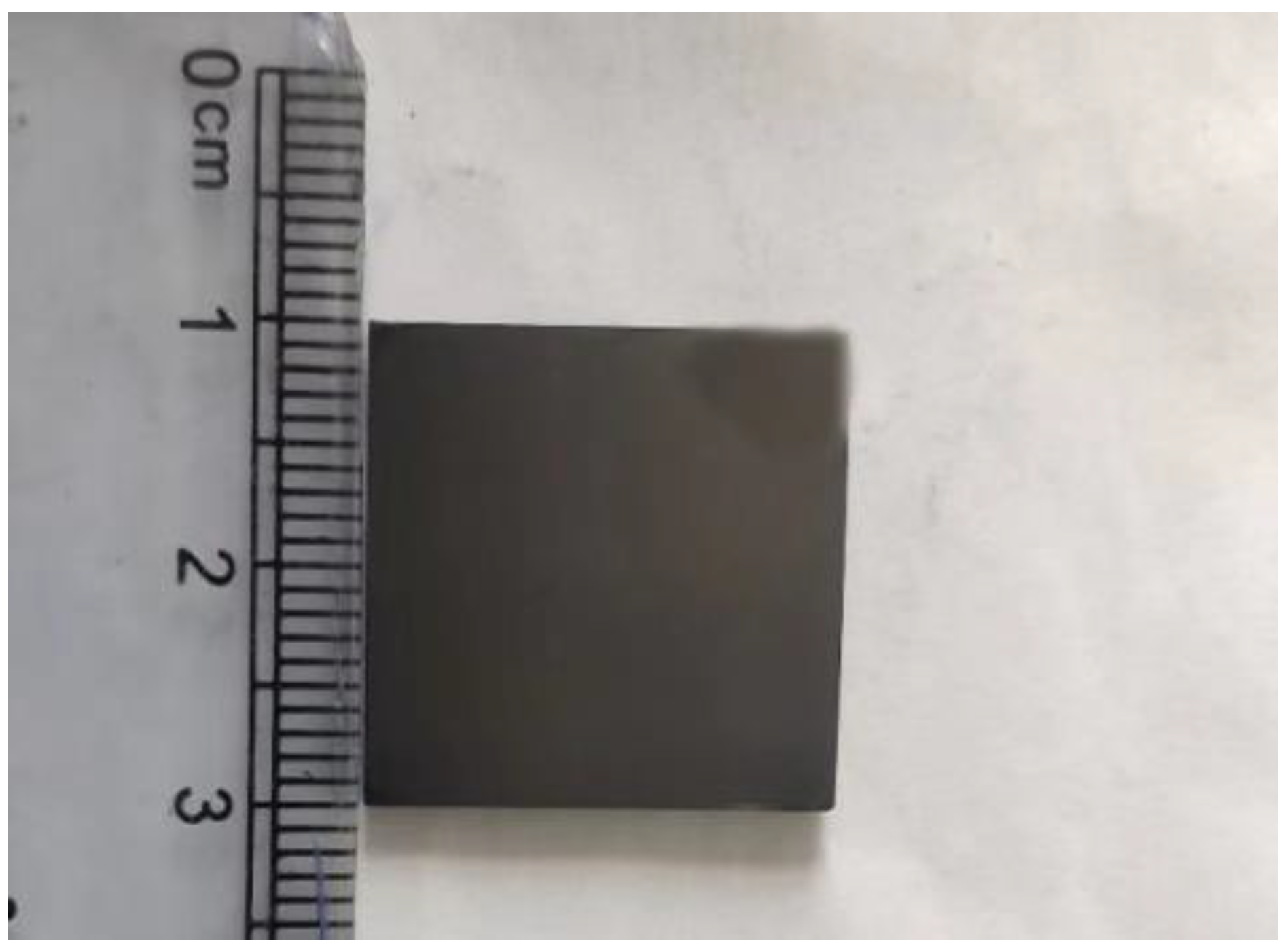
2. Preparation and Characterization

TD and TTTD films are prepared on both Ta substrate (99.96% purity) and silicon wafer (Si). The size of the Ta sheet used is 2 cm x 2 cm x 2 mm, and the size of the Si sheet is 2 cm × 2 cm × 1 mm. The films are prepared using the physical vapor deposition (PVD) method by Liaoning Beiyu Vacuum Co., Ltd. (DG-4-BY, Liaoning Beiyu Vacuum Co., Ltd., Shenyang, China). The external dimensions of the sample are shown in Figure 1. The purity of both the graphite target and titanium target is 99.99%, and the purity of both Ar and N2 is 99.99%. Before coating, the Ta substrate and Si wafer are, respectively, washed in deionized water and absolute ethanol for 15 min each to remove the contaminants on the substrate surface. After cleaning, the substrates are blown dry with N2, fixed on the rotating frame, and placed inside the vacuum chamber, and the mechanical pump and maintenance pump are turned on in turn to enter the vacuum stage. When the vacuum degree in the vacuum chamber reaches 5 × 10⁻³, the films start to be deposited. The deposition time of the Ti transition layer and DLC film in TD film is 15 min and 4 h, respectively. In order to ensure the consistency of deposition time, the deposition time of TiN film and DLC film in TTTD film is 30 min and 3.25 h, respectively. The deposition time of the titanium transition layer in the TTTD film is all 15 min. Finally, the PVD vacuum chamber is cooled down by means of circulating water. When the temperature is cooled to 70 °C, the vacuum chamber door is opened to take out the samples for sealing and preservation.
To analyze the carbon bond structure, Raman experiments are performed using a high-resolution Raman spectrometer (LabRAM HR Evolution, HORIBA JobinYvon, France). The excitation wavelength is 532 nm, and the spectral measurement range is 800–2000 cm−1. To ensure that the data are reliable, four different points are selected for each sample for testing. The data are processed and fitted by Origin 2018 software(OriginLab, 9.50.00, Hampton, NY, USA). Morphological observations are performed using a scanning electron microscope (SEM, Sigma 300, CARL ZEISS, Oberkocher, Germany). The acceleration voltage used is 5 eV.
In order to study the corrosion properties of TD film and TTTD film, electrochemical corrosion experiments are carried out using an electrochemical workstation (CHI760E, Shanghai Chenhua Instrument Co., Ltd., Shanghai, China). The pH value of normal human body fluid is between 7.35 and 7.45. For the purpose of simulating the weak alkaline environment of the human body, sodium bicarbonate solution (mass fraction of 5%, pH = 7.4, referred to as weak alkali) is prepared. To simulate the weakly acidic environment of human tissue lesions, a lactic acid solution (5% by mass, pH = 5.0, referred to as weak acid) is prepared. The dynamic potential polarization test and electrochemical impedance experiment are commonly used to characterize the corrosion resistance between thin films and substrates. The corrosion potential and corrosion current density are calculated by the Tafel extrapolation method [24]. The electrochemical corrosion experiment adopts a three-electrode system in which the Pt electrode is the counter electrode, the saturated calomel electrode (SCE) is the reference electrode, and the sample is the working electrode. The corrosion area of the corrosion experiment in solution is 1 cm2, the scanning frequency range is 10−2–105 Hz, the polarization potential range is −1–1 V, and the potential scanning rate is 0.001 V/s.
In order to measure the static contact angle, a contact angle measuring instrument (Zhongchen JC2000C1, Shanghai, China) is used for measurement. The measuring instrument includes two parts: a software system and a hardware system. The hardware system includes a manual three-dimensional platform, a manual sample feeding device, a digital CCD camera, a CCD tilting platform, a continuous zoom optical lens, and a 360° horizontal rotation platform. The software system is mainly used to measure the contact angle, advancing angle, receding angle, and other operations.
In order to measure the roughness of the film surface, a surface roughness meter (JD520, Beijing Jitai Keyi testing equipment Co., Ltd., Beijing, China) is used in this paper for roughness measurement, the distance of each measurement line is 0.8 mm, and five different areas are selected. The five measurements were averaged to reduce measurement error.

3. Results and Discussion

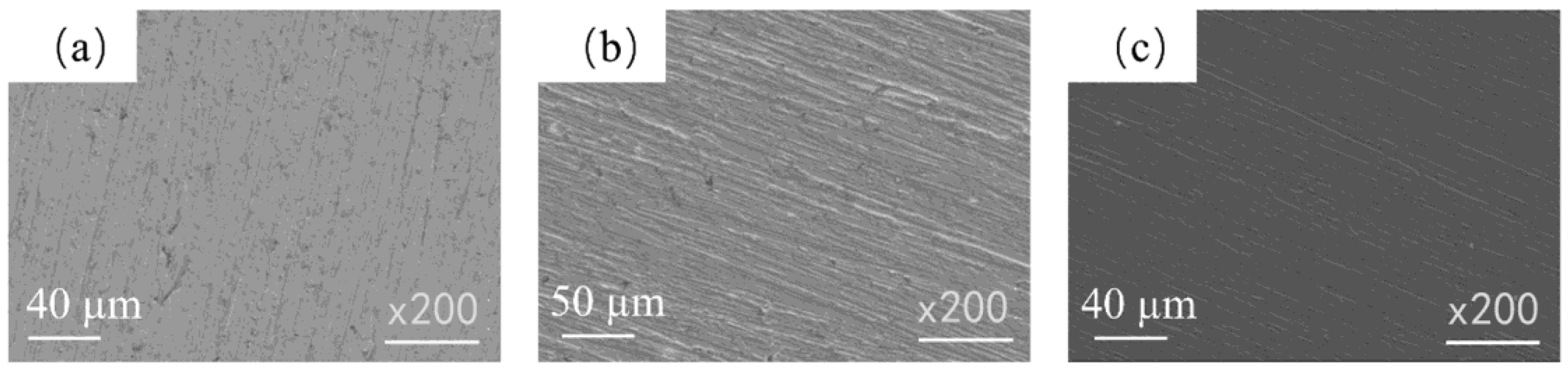
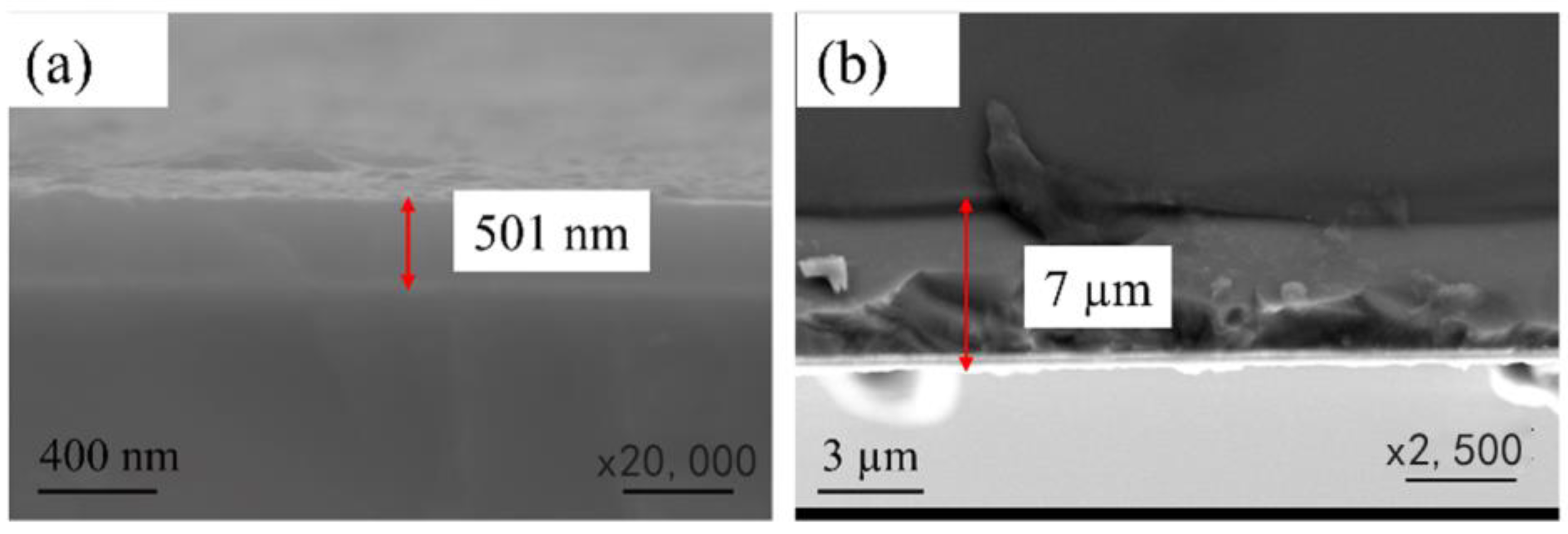
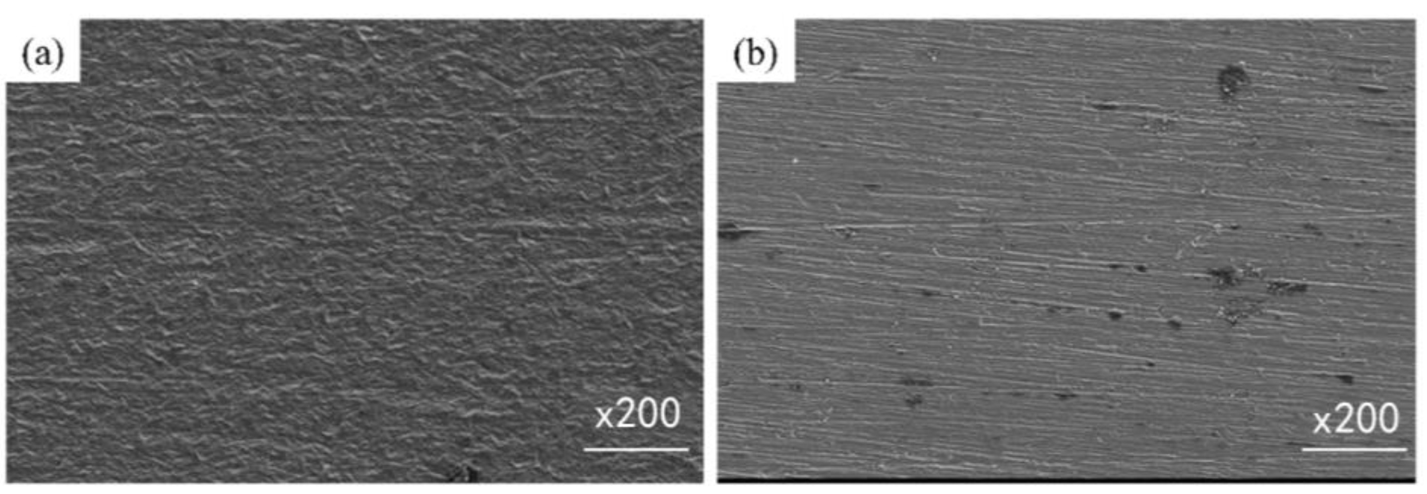
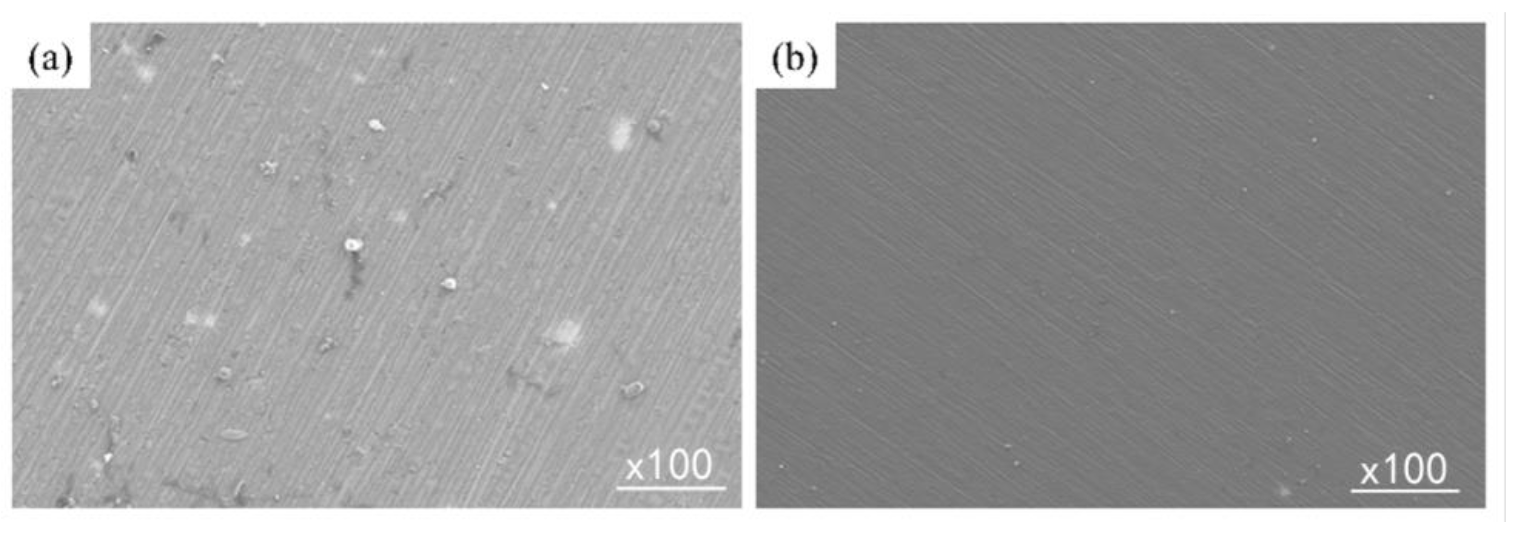
3.1. Surface Morphology

The surface morphologies of the TD and TTTD films are shown in Figure 2. From Figure 2a, it can be found that the surface of the Ta substrate has deep scratches and many deep pits. By comparing the surface morphology, it can be found that the surface of the TTTD film is the densest and smoothest, with the shallowest groove marks and no pits on the surface. This is due to the thicker thickness of the TTTD film, which covers a certain depth of scratches (left during polishing), resulting in a smoother and denser surface. Deep grooves can still be seen on the surface of the TD film, but the pits are significantly reduced. This is because the thickness of the TD film is thin and cannot cover the scratches left after polishing, resulting in a rougher surface. The cross-sectional morphologies of the TD and TTTD films are shown in Figure 3. By comparing the cross-sectional morphologies of the TD film and the TTTD film, it can be known that the growth rate of the DLC film on the titanium nitride intermediate layer is faster.

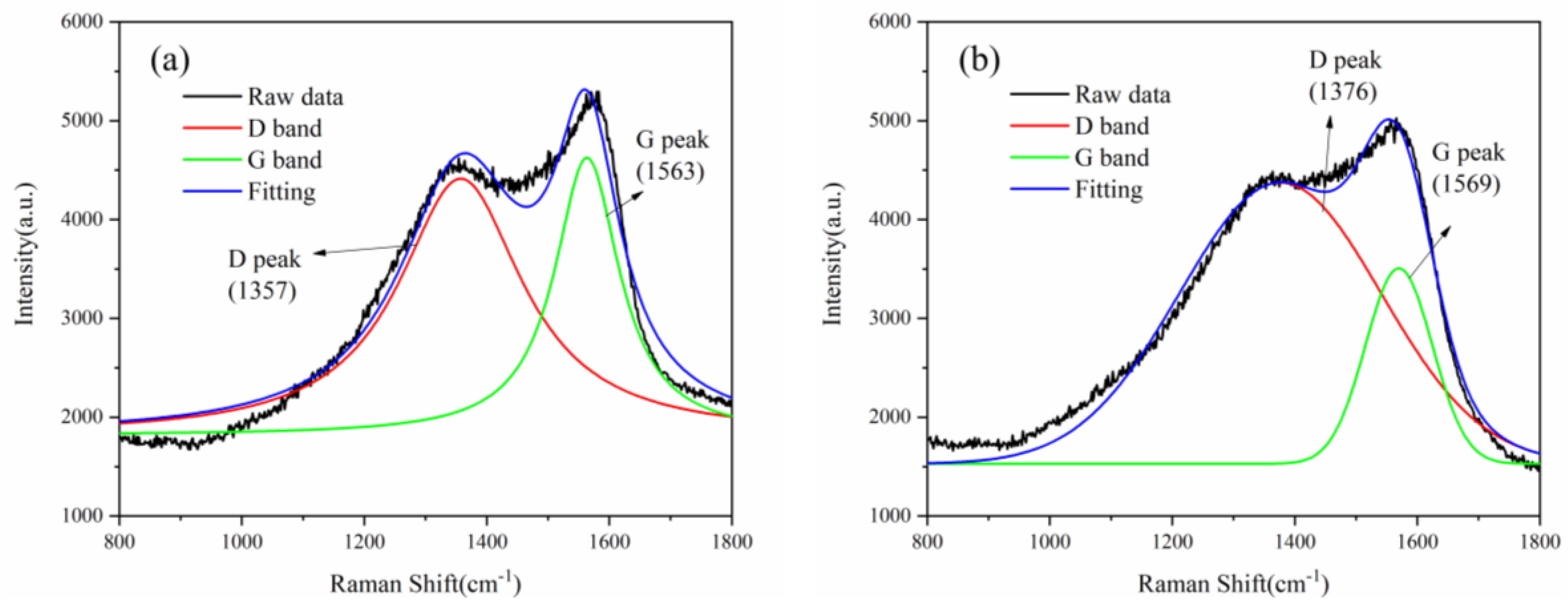
3.2. Raman Spectroscopy

The Raman spectra of the TD film and the TTTD film are shown in Figure 4. The existence of the DLC film can be determined from the D peak and G peak of the Raman spectrum. The D peak is attributed to the breathing vibration of the aromatic ring carbon, and the G peak is caused by the stretching vibration of the aromatic ring or chain carbon [25,26]. By calculating the area, it can be obtained that the ID/IG value of the TD film is 1.05, and the ID/IG value of the TTTD film is 1.18. Generally, the ratio of ID/IG can be used to characterize the ratio of sp2/sp3 [25]. The sp2/sp3 value of the TTTD film is higher than that of the TD film, which indicates that the TTTD film has a higher sp2 content and a more ordered structure. From this, it can be speculated that the corrosion resistance of the TTTD film should be worse. However, the result is quite the opposite, which is discussed in a later section.

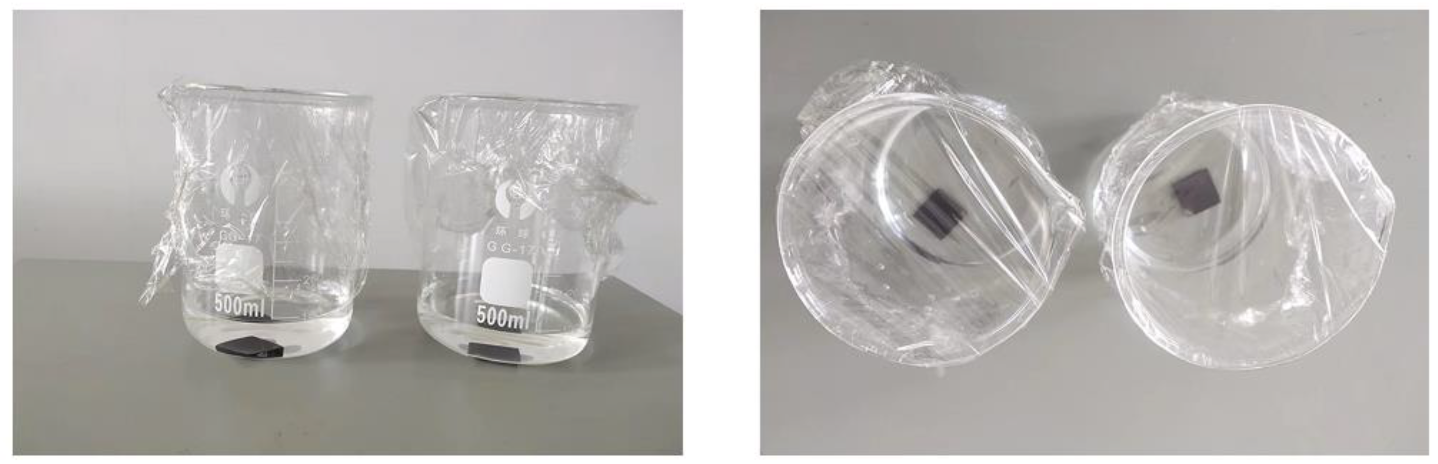
3.3. Corrosion Pattern

In order to characterize the corrosion of the films when immersed in the solution for a long period of time, a 20-day immersion experiment was carried out. The immersion experiments of the samples are shown in Figure 5.
The surface morphologies of the TD film and TTTD film after 20 days of immersion in weak alkali and weak acid solutions, respectively, are shown in Figure 6 and Figure 7. It can be found from the corrosive morphology that in the weak alkaline solution, many corrosion pits appear on the surface of the TD film, while only a small amount of bulk material is formed on the surface of the TTTD film, and the morphology is clearly visible. In the weak acid solution, the surface of the TD film with many corrosion pits is formed by bulk substances, while the surface of the TTTD film is smooth and dense without corrosion pits and substances. In the end, it can be concluded that the higher the sp2/sp3 value, the better the corrosion resistance of the film. This conclusion can be verified by Raman spectroscopy experiments.

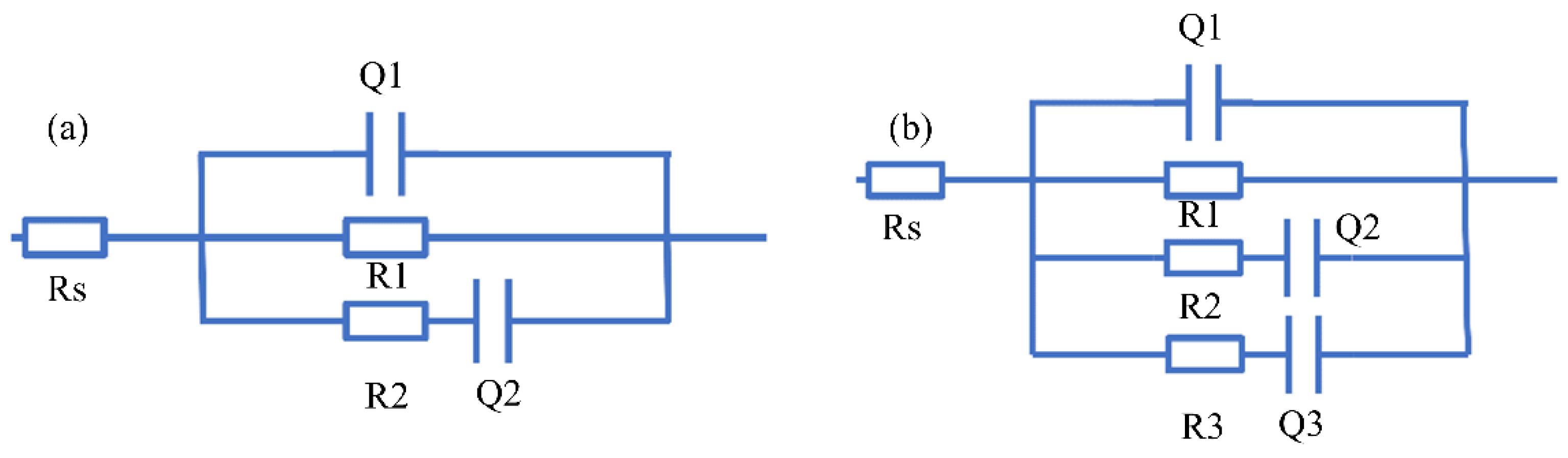
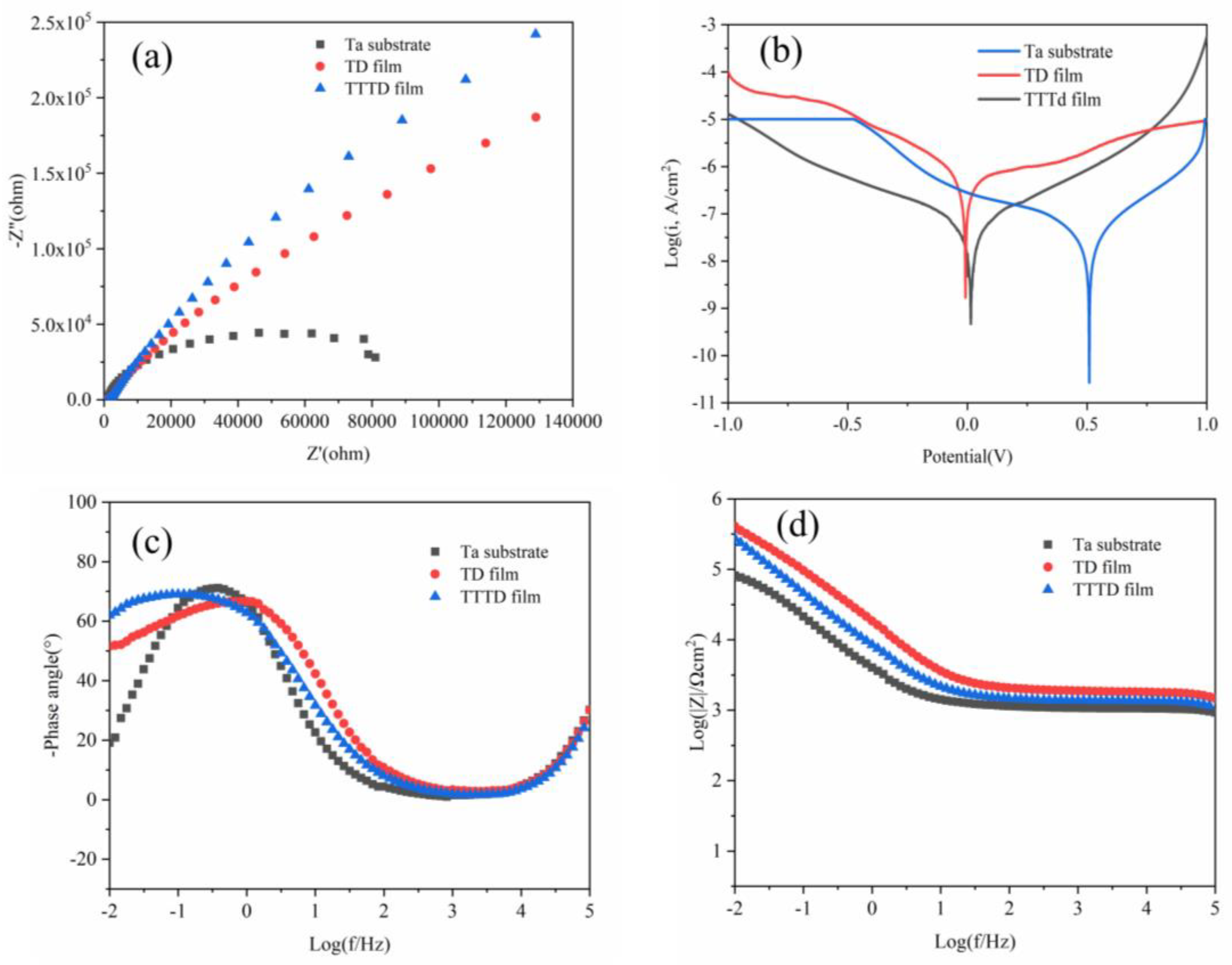
3.4. Corrosion Analysis

3.4.1. Weak Alkaline Environment

Figure 8 shows the polarization curve, Bode, and Nyquist diagram of electrochemical corrosion of the TD film and TTTD film in a weak alkaline environment. From Figure 8a, it can be found that the phase angle of both the TD and TTTD films move to high angles at high frequencies, indicating a corresponding increase in capacitance. In Figure 8c, it can be seen that the capacitive arc radius of the TTTD film is the largest, followed by the capacitive arc radius of the TD film, and the capacitive arc radius of the Ta substrate is the smallest. The impedance of TD and TTTD films is higher than that of the Ta substrate. This indicates that both the TD and TTTD films are more resistant to corrosion than the Ta substrate, and the TTTD film has the strongest corrosion resistance. It can be seen from Figure 8d that the corrosion potential of the TTTD film is the highest, and the corrosion potential of the Ta substrate is the lowest. The corrosion current density of both TD and TTTD films is an order of magnitude lower than that of the Ta substrate. Generally, the corrosion rate is proportional to the corrosion current density, and the difficulty of corrosion is reflected by the corrosion potential. Thus, both the TD film and the TTTD film prepared on Ta substrate contribute to reducing the corrosion rate. However, the TTTD film offers a greater degree of protection. The corrosion current density, corrosion potential, and polarization resistance are listed in Table 1.
In order to obtain quantitative data on the electrochemical impedance of the film and the substrate in a weak alkaline solution, the equivalent circuit fitting of the electrochemical impedance data was performed using Zview2 software (3.2.0.49), as shown in Figure 9. In Figure 9a, Rs is the solution resistance between the film and the electrode, Q1 is the capacitance of the DLC film, R1 is the conduction resistance of the solution passing through the voids and defects of the film, R2 is the polarization resistance between the film and the substrate, and Q2 is the electric double-layer capacitance generated by the solution reaching the interface between the film and the substrate. The size of R2 reflects the degree of corrosion resistance. The larger the value of R2, the stronger the corrosion resistance of the film. The electrochemical impedance fitting data of the TD film in a weak alkaline solution are shown in Table 2. In Figure 9b, Rs is the solution resistance between the DLC film and the electrode, Q1 is the capacitance of the DLC film, R1 is the conduction resistance of the solution passing through the voids and defects of the DLC film, R2 is the conduction resistance of the passivation film voids and defects, Q2 is the capacitance of the passivation film, R3 is the polarization resistance between the film and the substrate, and Q3 is the electric double layer capacitance generated by the solution reaching the interface between the film and the substrate. From the phase angle diagram, it can be found that the TTTD film is closer to 90° in the low-frequency region, exhibiting capacitive characteristics. The fitting circuit in Figure 9b is in good agreement with the actual measured curve. The electrochemical impedance fitting data of the TTTD membrane in a weak alkaline solution are shown in Table 3.
The porosity of the film can be calculated by parameters obtained from electrochemical experiments, and the calculation formula is shown below. P = Rps/Rp × 10−|∆φcorr/βa|, where P is the total void of the film, Rp is the polarization resistance of the film, Rps is the polarization resistance of the substrate, and ∆φcorr is the corrosion potential between the film and the substrate difference, βa is the Tafel slope of the substrate anode [27]. The corrosion protection efficiency of the film can be calculated from the data obtained from the polarization curve, and the formula is shown below. Pe = (1 − Jcorr/J0corr), where Jcorr and J0corr represent the corrosion current density of the film and substrate, respectively [27]. In a weak alkaline solution, the calculated porosity and corrosion protection efficiency of TD film are 0.55 and 43.36%, respectively; the porosity and corrosion protection efficiency of TTTD film are 0.03 and 97.96%, respectively. This indicates that the TTTD film has fewer voids.

3.4.2. Weak Acid Environment

Figure 10 shows the polarization curve, Bode diagram, and Nyquist diagram of electrochemical corrosion of a TD film and TTTD film in a weak acid environment. It can be found from the Nyquist curve that the capacitive arc radius of the TTTD film is the largest. From the polarization curve, it can be found that the corrosion potential of the TD film in the weak acid solution is lower than that of the Ta substrate, and the corrosion current density is higher than that of the Ta substrate. However, the corrosion current density of the TTTD film in the weak acid solution is the lowest, and the corrosion potential is the highest. In addition, in the cathode region, a passivation region appeared in the TTTD film. These all indicate that the TTTD film has better corrosion resistance. It can be found in the Bode diagram that the phase angle changes towards a high angle in the high-frequency region, which indicates that the capacitance increases accordingly. The corrosion current density, corrosion potential, and polarization resistance are listed in Table 2.
In order to obtain the electrochemical corrosion behavior of the film in a weak acid solution, the equivalent circuit was fitted to the electrochemical impedance data using Zview2 software (3.2.0.49), as shown in Figure 11. The fitted data for the electrochemical impedance is presented in Table 3. In Figure 11a, Rs is the solution resistance between the film and the electrode, Q1 is the capacitance of the DLC film, R1 is the conduction resistance of the solution passing through the voids and defects of the film, R2 is the conduction resistance of the solution passing through the corrosion product, and Q2 is the capacitance of the corrosion product, R3 is the polarization resistance between the film and the substrate, and Q3 is the electric double layer capacitance generated by the solution reaching the interface between the film and the substrate. In Figure 11b, Rs is the solution resistance between the DLC film and the electrode, Q1 is the capacitance of the DLC film, R1 is the conduction resistance of the solution passing through the voids and defects of the DLC film, R2 is the conduction resistance of the passivation film voids and defects, Q2 is the capacitance of the passivation film, R3 is the polarization resistance between the film and the substrate, and Q3 is the electric double layer capacitance generated by the solution reaching the interface between the film and the substrate. Electrochemical impedance fitting data of TD film and TTTD film in weak acid solution are listed in Table 4. In weak acid solution, the calculated porosity and corrosion protection efficiency of TD film are 14.06 and −18.76%, respectively; the porosity and corrosion protection efficiency of TTTD film are 0.79 and 21.64%, respectively. This indicates that the TTTD film has a denser structure with fewer voids. This result is consistent with that observed for surface topography.

3.5. Contact Angle and Roughness

The results of the contact angle measurement are shown in Figure 12. The wettability of thin films is related to corrosion. Wettability is usually characterized by a static contact angle [28]. If the static contact angle θ < 90°, the material behaves hydrophilic [29]; if the static contact angle is 90° < θ < 180°, the material behaves hydrophobic. Studies have shown that the contact angle is not only related to surface roughness but also to wettability. The better the wettability, the better the hydrophilicity.
From the contact angle results in Figure 12, it can be found that the contact angles of the TD film and the TTTD film are both less than 90°, showing hydrophilicity; in the weak acid and weak alkali solutions, the contact angle of the TD film is larger than that of the TTTD film. The contact angles of TD and TTTD films in weak acid environments are larger than those in weak alkali environments. This is caused by the difference in the surface structure of the films.
In weak alkaline solutions, the contact angle of the TTTD film is the smallest. In a weak acid solution, the contact angle of the TD film is the largest, and the contact angle of the TTTD film is the second largest. Theoretically, the TTTD film is better hydrophilic and less corrosion resistant [30], but the results are diametrically opposite. This result can be verified by electrochemical corrosion experiments.
The surface free energy is another important parameter to characterize hydrophobicity. In this paper, the Owens–Wendt–Rabel–Kaelble (OWRK) method is used to calculate the surface free energy [31]. The calculation formula is as follows.
γ L   ( 1 + cos θ ) = ( γ S D γ L D ) 1 / 2 + ( γ S P γ L P ) 1 / 2  
γ S   = γ S D + γ S P
where γ L is the total surface tension of the liquid, γ L D and γ L P are the dispersive and polar components of the liquid, γ S is the total surface tension of the solid, and γ S D and γ S P are the dispersive and polar components of the solid. The polar component of the liquid can be obtained by reviewing the data. The surface free energy of the solid can be obtained by combining Equations (1) and (2). The results show that the surface free energy of DLC films in weak alkaline solutions (44 mJ/m2) is greater than that in weak acid solutions (42 mJ/m2). This indicates that the DLC films have better wettability in weak alkaline solutions. This result is consistent with the measurement of the contact angle.
Usually, the contact angle is related to the surface roughness [30]. In order to obtain the size of the surface roughness of the film, the roughness was measured with a surface roughness meter. The measurement results are shown in Figure 13. What stands out in this figure is the variability of the surface roughness. It can be seen from the profile diagram that the roughness of the substrate and the TD film are not much different, while the roughness of the TTTD film is significantly reduced. After averaging the five measurements, the roughness can be obtained. After calculation, it was found that the roughness of the Ta substrate was 0.19 µm, the roughness of the TD film was 0.18 µm, and the roughness of the TTTD film was 0.14 µm. The TD film has the smallest surface roughness. This result is consistent with that obtained from the surface topography, which further verifies the trend of contact angle variation.

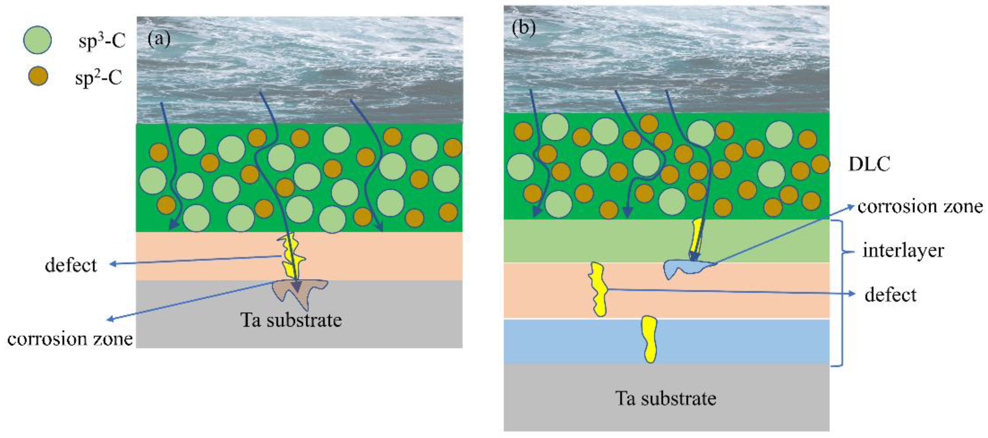
3.6. Corrosion Mechanism

DLC films reduce the corrosion of Ta substrates. The main factors affecting the protection of the top layer DLC film against substrate corrosion are surface morphology, internal structure, and contact angle. The corrosion mechanisms of the TD film and the TTTD film are shown in Figure 14. By summarizing the above experiments, it can be found that there are three reasons why TTTD films are more resistant to corrosion: first, the solution enters through the voids of the DLC film to form tantalum oxide at the substrate interface, increasing the possibility of DLC film peeling off and leading to a decrease in the corrosion resistance of the TD film; second, TTTD films form passivation films during the corrosion process, which prevent the solution from invading the substrate; third, defects in TTTD films are compensated by the designed multilayer structure [32]; fourth, TTTD films have a higher sp2/sp3 content and a higher relative content of sp2, which leads to a reduction in the polar fraction and thus enhances hydrophobicity [33]. Ultimately, it can be concluded that the internal structure is the key factor affecting the performance of DLC films on substrate corrosion protection.

4. Conclusions

In this paper, two different films were prepared by magnetron sputtering, and their corrosion properties in lactic acid and sodium bicarbonate solutions were investigated. The specific conclusions obtained are as follows: Both TD film and TTTD film can mask the defects of the Ta substrate, but the TTTD film with higher thickness can make the surface denser. The surface morphology after 20 days of immersion was observed by SEM, and it was found that the surface of the TTTD film showed almost no corrosion pits. The sp2 content of the TTTD film was higher, but the dense structure and less porosity led to higher corrosion resistance. In sodium bicarbonate solution, the polarization potential of the TD film was more negative than that of the Ta substrate, and the corrosion current density was higher; the polarization potential of the TTTD film changed from negative to positive, and the corrosion current density decreased by one order of magnitude; the capacitive arc resistance radius of the TTTD film was the largest. In lactic acid solution, the corrosion potential of the TD film and Ta substrate are not much different, and the corrosion current density increases by one order of magnitude; the polarization potential of TTTD film changes from negative to positive, and the corrosion current density is the lowest; the radius of capacitive arc resistance of TTTD film is also the largest. This is because the TTTD film forms a passivation film during the corrosion process, which prevents the solution from invading the substrate. The contact angle of TTTD film is smaller than that of TD film, which is more hydrophilic. This is contrary to the results obtained from electrochemical corrosion experiments. This indicates that the corrosion resistance of the TTTD film is mainly determined by the surface and internal structure, and the contact angle has less influence on the corrosion resistance. In summary, TTTD films have a multilayer structure that prevents solution penetration near the substrate and can reduce film defects for optimal corrosion resistance.

Author Contributions

Conceptualization, S.Z. and D.G.; methodology, D.G.; software, D.G.; validation, D.G., T.H. and S.W.; Formal analysis, D.G.; investigation, S.W.; resources, S.Z.; data curation, D.G.; writing—original draft preparation, D.G.; writing—review and editing, S.Z.; visualization, D.G.; supervision, X.M. and F.G.; project administration, S.Z.; funding acquisition, S.Z.. All authors have read and agreed to the published version of the manuscript.

Funding

This work is supported by the National Natural Science Foundation of China (No. 51861031).

Institutional Review Board Statement

Not applicable.

Informed Consent Statement

Not applicable.

Data Availability Statement

Not applicable.

Conflicts of Interest

The authors declare no conflict of interest.

References

  1. Jia, D.; Wei, J.; Duan, X.; Zhang, R. Analysis of the disease burden of osteoarthritisi in China from global perspective. Mod. Prev. Med. 2022, 49, 2312–2316. [Google Scholar]
  2. Wu, B.J.; Deng, Q.Y.; Leng, Y.X.; Wang, C.M.; Huang, N. Characterization of adsorption and lubrication of synovial fluid proteins and HA on DLC joint bearings surface. Surf. Coat. Technol. 2017, 320, 320–332. [Google Scholar] [CrossRef]
  3. Wang, Q.; Guo, G.; Song, G.; Zhang, C.; Liu, Z.; Chen, D. Research progress of bioprosthesis materials for artificial joints. J. Med. Res. 2020, 49, 171–173+178. [Google Scholar]
  4. Gong, Y.L.; Jing, P.P.; Zhou, Y.J.; Ma, D.L.; Deng, Q.Y.; Shen, R.; Huang, N.; Leng, Y.X. Formation of Rod-shaped Wear Debris and the Graphitization Tendency of Cu-doped Hydrogenated Diamond-like Carbon Films. Diam. Relat. Mater. 2020, 102, 107654. [Google Scholar] [CrossRef]
  5. Wu, X. Study on Surface Treatment of Metal Materials for Artificial Joints. China Plant Eng. 2021, 17, 102–103. [Google Scholar]
  6. Yi, X. Effects of Artificial Joint Replacement on the Quality of Life and Pain Degree of Elderly Patients with Femoral Intertrochanteric Fractures. WJNM 2022, 8, 23–26+31. [Google Scholar]
  7. Shi, X.; Wu, X.; Ma, X.; Liu, Y.; He, P.; Luo, Y. Biomedical applications of tantalum-based materials and the underlying mechanisms. J. Func. Mater. 2019, 50, 12001–12006. [Google Scholar]
  8. Chen, H.; Song, Z.; Luo, Y. Study on Precision Cutting Process of the Ta-12W Alloy. Mach. Des. Manuf. 2012, 9, 164–166. [Google Scholar]
  9. Deng, Z.; Yan, X.; Dong, D.; Wang, Y.; Ma, W.; Liu, M. Study on Process for Medical Pure Tantalum Parts Prepared by Selective Laser Melting (SLM) and Mechanical Properties. Hot Work. Tech 2021, 50, 76–81. [Google Scholar]
  10. Zhang, X.; Xu, R.; Wu, G.; Bai, X. Different biomaterial prostheses in joint replacement. CJTER 2012, 16, 8869–8874. [Google Scholar]
  11. Shi, W.; Wang, Y. Handering Treatment on Tantalum Surface. Heat Treat. Met. 2000, 5, 27–29. [Google Scholar]
  12. Yao, J.; Wang, Y. The Research of Crystalline Diamond Films Depositing on Ta Spinneret. New Tec. New Pro 2007, 2, 74–76+74. [Google Scholar]
  13. Pornwasa, W.; Nattapo, L.P.; Kanjana, T.; Chanan, E. Improvement of corrosion resistance and biocompatibility of 316L stainless steel for joint replacement application by Ti-doped and Ti-interlayered DLC films. Surf. Coat. Technol. 2021, 425, 127734. [Google Scholar]
  14. Nakatani, T.; Takeuchi, H.; Wada, A.; Yamashita, S. Investigation of Anti-Corrosive Performance of a Si-Doped DLC-Coated Magnesium Alloy Stent Deposited by RF-Plasma CVD. J. Photopolym. Sci. Tec. 2019, 32, 511–517. [Google Scholar] [CrossRef] [Green Version]
  15. Sara, K.; Eiman, A.; Mohammad, M.; Saeb, M.; Vahabi, H.; Kokanyan, N.; Laheurte, P. Magnetron-sputtered copper/diamond-like carbon composite thin films with super anti-corrosion properties. Surf. Coat. Technol. 2018, 333, 148–157. [Google Scholar]
  16. Shang, L.; Gou, C.; Li, W.; He, D.; Wang, S. Effect of microstructure and mechanical properties on the tribological and electrochemical performances of Si/DLC films under HCl corrosive environment. Diam. Relat. Mater. 2021, 116, 108385. [Google Scholar] [CrossRef]
  17. Maxime, C.; Stéphane, T.; Yan, B.; Tatoulian, M.; Pireaux, J.; Mantovani, D. Controlled distribution and clustering of silver in Ag-DLC nanocomposite coatings using a hybrid plasma approach. ACS Appl. Mater. Inter. 2016, 8, 21020–21027. [Google Scholar]
  18. Dorota, L.; Błażej, B.; Witold, K.; Grabarczyk, J.; Svobodova, L.; Szatkiewicz, T.; Mitura, K. The DLC Coating on 316L Stainless Steel Stochastic Voronoi Tessellation Structures Obtained by Binder Jetting Additive Manufacturing for Potential Biomedical Applications. Coatings 2022, 12, 1373. [Google Scholar]
  19. Guo, Z.; Wang, R.; Yang, H.; Chen, J.; Lin, R.; Wei, S.; Li, B. Preparation and Performance Study of Si-DLC Based on Ion Deposition of Different Multiple Gradient Transition Layers. Coatings 2022, 12, 882. [Google Scholar] [CrossRef]
  20. Cui, M.; Pu, J.; Zhang, G.; Wang, L.; Xue, Q. The corrosion behaviors of multilayer diamond-like carbon coatings: Influence of deposition periods and corrosive medium. RSC Adv. 2016, 6, 28570. [Google Scholar] [CrossRef]
  21. Cao, X.; Shang, L.; Zhang, G.; Ding, Q. Simultaneously Improving the Corrosion Resistance and Wear Resistance of Internal Surface of Aluminum Pipe by Using Multilayer Diamond-Like Carbon-Si Coatings. J. Mater. Eng. Perform. 2022, 22, 6678–6685. [Google Scholar] [CrossRef]
  22. Iijima, Y.; Harigai, T.; Isono, R.; Degai, S.; Tanimoto, T.; Suda, Y.; Takikawa, H.; Yasui, H.; Kaneko, S.; Kunitsugu, S.; et al. Preparation of multi-layer film consisting of hydrogen-free DLC and nitrogen-containing DLC for conductive hard coating. AIP Conf. Proc. 2018, 1929, 20024. [Google Scholar]
  23. Dai, W.; Gao, X.; Liu, J.; Kwon, S.-H.; Wang, Q. Compositionally modulated multilayer diamond-like carbon coatings with AlTiSi multi-doping by reactive high power impulse magnetron sputtering. Appl. Surf. Sci. 2017, 425, 855–861. [Google Scholar] [CrossRef]
  24. Guan, X.; Wang, Y.; Wang, J.; Xue, Q. Adaptive capacities of chromium doped graphite-like carbon films in aggressive solutions with variable pH. Tribol. Int. 2016, 96, 307–316. [Google Scholar] [CrossRef]
  25. Ding, J.C.; Mei, H.; Jeong, S.; Zheng, J.; Wang, Q.M.; Kim, K.H. Effect of bias voltage on the microstructure and properties of Nb-DLC films prepared by a hybrid sputtering system. J. Alloy. Compd. 2021, 861, 158505. [Google Scholar] [CrossRef]
  26. Catena, A.; Guo, Q.; Kunze, M.R.; Agnello, S.; Gelardi, F.M.; Wehner, S.; Fischer, C.B. Morphological and Chemical Evolution of Gradually Deposited Diamond-Like Carbon Films on Polyethylene Terephthalate: From Subplantation Processes to Structural Reorganization by Intrinsic Stress Release Phenomena. ACS Appl. Mater. Inter. 2016, 8, 10636–10646. [Google Scholar] [CrossRef] [Green Version]
  27. Seyed, E.M.; Nastaran, N.; Mohabbat, A.; Shammakhi, H. Corrosion performance and tribological behavior of diamond-like carbon based coating applied on Ni−Al−bronze alloy. T Nonferr. Metal. Soc. 2021, 31, 499–511. [Google Scholar]
  28. Zhang, L.; Pu, J.; Wang, L.; Xue, Q. Frictional dependence of graphene and carbon nanotube in diamond-like carbon/ionic liquids hybrid films in vacuum. Carbon 2014, 80, 734–745. [Google Scholar] [CrossRef]
  29. Liu, L.; Zhou, S.; Zhuang, X.; Wang, Y.; Ma, L. Wettability and Corrosion Resistance of Iron-containing Diamond-like Film. Surf. Tech. 2017, 46, 169–174. [Google Scholar]
  30. Li, X.; Jiang, L.; Li, L.; Yan, Y. Influence of Acid Etching on Wettability of Ion-exchanged Aluminosilicate Float Glass. J. Aeronaut. Mater. 2016, 36, 54–60. [Google Scholar]
  31. Simič, R.; Kalin, M.; Kovač, J.; Jakša, G. Adsorption of alcohols and fatty acids onto hydrogenated (a-C:H) DLC coatings. Appl. Surf. Sci. 2016, 363, 466–476. [Google Scholar] [CrossRef] [Green Version]
  32. Zhou, J.; Hu, C.; Chen, L. Structure, mechanical properties and thermal stability of CrAlNbN/TiN multilayers. Vacuum 2021, 188, 110182. [Google Scholar] [CrossRef]
  33. Sui, X.; Xu, R.; Liu, J.; Zhang, S.; Wu, Y.; Yang, J.; Hao, J. Tailoring the Tribocorrosion and Antifouling Performance of (Cr, Cu)-GLC Coatings for Marine Application. ACS Appl. Mater. Inter. 2018, 10, 36531–36539. [Google Scholar] [CrossRef] [PubMed]
Figure 1. The external dimensions of the sample.
Coatings 12 01776 g001
Figure 2. Surface topography of (a) Ta substrate, (b) TD film and (c) TTTD film.
Coatings 12 01776 g002
Figure 3. Cross-sectional morphologies of (a) TD and (b) TTTD films.
Coatings 12 01776 g003
Figure 4. Raman spectrum: (a) TD film (b) TTTD film.
Coatings 12 01776 g004
Figure 5. The immersion experiments of the samples.
Coatings 12 01776 g005
Figure 6. Surface morphology after soaking in weak alkaline solution for 20 days: (a) TD film (b) TTTD film.
Coatings 12 01776 g006
Figure 7. Surface morphology after soaking in weak acid solution for 20 days: (a) TD film (b) TTTD film.
Coatings 12 01776 g007
Figure 8. Corrosion test of Ta substrate, TD film and TTTD film in weak alkaline environment: (a) Nyquist curve, (b) polarization curve, (c) phase angle diagram, (d) impedance value.
Coatings 12 01776 g008
Figure 9. Fitted equivalent circuit diagram in weak alkaline solution: (a) TD film (b) TTTD film. Here, Rs is the solution resistance between the DLC film and the electrode, Q1 is the capacitance of the DLC film, R1 is the conduction resistance of the solution passing through the voids and defects of the DLC film, R2 is the conduction resistance of the passivation film voids and defects, Q2 is the capacitance of the passivation film, R3 is the polarization resistance between the film and the substrate, and Q3 is the electric double layer capacitance generated by the solution reaching the interface between the film and the substrate.
Coatings 12 01776 g009
Figure 10. Corrosion test of Ta substrate, TD film, and TTTD film in weak acid environment: (a) Nyquist curve, (b) polarization curve, (c) phase angle diagram, (d) impedance value.
Coatings 12 01776 g010
Figure 11. Fitted equivalent circuit diagram in weak acid solution: (a) TD film (b) TTTD film. Here, Rs is the solution resistance between the DLC film and the electrode, Q1 is the capacitance of the DLC film, R1 is the conduction resistance of the solution passing through the voids and defects of the DLC film, R2 is the conduction resistance of the passivation film voids and defects, Q2 is the capacitance of the passivation film, R3 is the polarization resistance between the film and the substrate, and Q3 is the electric double layer capacitance generated by the solution reaching the interface between the film and the substrate.
Coatings 12 01776 g011
Figure 12. Contact angles of Ta substrate, TD and TTTD films in weak acid and weak base environments.
Coatings 12 01776 g012
Figure 13. Surface roughness profile topography: (a) Ta substrate (b) TD film (c) TTTD film.
Coatings 12 01776 g013
Figure 14. Corrosion mechanisms of (a) TD film and (b) TTTD film.
Coatings 12 01776 g014
Table 1. Corrosion current density and corrosion potential of substrate, TD and TTTD films in weak alkali environment.
SampleIcorr (A/cm2)Ecorr (V)Rp (Ω cm2)
Ta2.74 × 10−6−0.1932.2 × 104
TD film1.552 × 10−6−0.1874.0 × 104
TTTD film5.586 × 10−60.4037.38 × 105
Table 2. Electrochemical impedance fitting data of TD film and TTTD film in weak alkaline solution.
SampleRs
(Ω cm2)
R1
(Ω cm2)
Q1
(F cm−2)
R2
(Ω cm2)
Q2
(F cm−2)
R3
(Ω cm2)
Q3
(F cm−2)
TD film21.656.065 × 1052.718 × 10−51545.478 × 10−5--
TTTD film3.163 × 10−22.408 × 1062.328 × 10−889.535.413 × 10−718.823.725 × 10−5
Table 3. Corrosion current density and corrosion potential of substrate, TD and TTTD films in weak alkaline solution.
SampleIcorr (A/cm2)Ecorr (V)Rp (Ω cm2)
Ta3.049 × 10−80.0141.35 × 106
TD film6.025 × 10−7−0.0089.6 × 104
TTTD film2.389 × 10−80.5091.7 × 106
Table 4. Electrochemical impedance fitting data of TD film and TTTD film in weak acid solution.
SampleRs
(Ω cm2)
R1
(Ω cm2)
Q1
(F cm−2)
R2
(Ω cm2)
Q2
(F cm−2)
R3
(Ω cm2)
Q3
(F cm−2)
TD film241.5829.41.199 × 10−9104.56.372 × 10−5141.91.712 × 10−5
TTTD film346.510131.259 × 10−92.044 × 1063.083 × 10−554.932.914 × 10−5
Publisher’s Note: MDPI stays neutral with regard to jurisdictional claims in published maps and institutional affiliations.

