
Pitting Performance of Cold- and Hot-Rolled Nickel-Saving High-Strength Metastable Austenitic Stainless Steel
1
Zhejiang Key Laboratory of Robotics and Intelligent Manufacturing Equipment Technology, Ningbo Institute of Materials Technology and Engineering, Chinese Academy of Sciences, Ningbo 315201, China
2
Key Laboratory of Impact and Safety Engineering of Ministry of Education, Part Rolling Key Laboratory of Zhejiang Province, School of Mechanical Engineering and Mechanics, Ningbo University, Ningbo 315211, China
3
Guangxi Beigang New Materials Co., Ltd., Nanning 536000, China
4
Ningbo Physis Technology Co., Ltd., Ningbo 315334, China
*
Authors to whom correspondence should be addressed.
Coatings 2022, 12(12), 1869; https://doi.org/10.3390/coatings12121869
Submission received: 22 October 2022
/
Revised: 25 November 2022
/
Accepted: 27 November 2022
/
Published: 1 December 2022
(This article belongs to the Special Issue Corrosion Resistance, Mechanical Properties and Characterization of Metallic Materials and Coatings)
Abstract
:Nowadays, nickel-saving metastable austenitic stainless steel (MASS) has become the right solution to meeting the growing requirement of higher strength, better corrosion resistance and more cost saving for the automobile industry. Better understanding of the pitting mechanism of the MASS after either cold- or hot-rolled can offer guidance for the producing of high-performance automobile steel. In the current work, for uncovering the pitting mechanism of the cold- and hot-rolled MASS, the microstructural evolution and pitting performance of nickel-saving metastable austenitic stainless (MASS) steel after cold- (CR) and hot-rolling (HR) were researched via electron microscopy technique and electrochemical methods. Austenite composites the main phase of the MASS. Small amounts of martensite film were proven to form in the MASS. The precipitation of Cr-rich M23C6 carbides was observed in the CR-MASS, while no carbides existed in the HR-MASS. The pitting resistance of the HR-MASS was better than the CR-MASS, which could be attributed to the fact that the stable pits in CR-MASS were initiated near the carbides, whereas the MnS inclusion would serve as the initiation sites for stable pits in HR-MASS. Findings in this work will provide a guidance for developing new generation MASS for automobile industry.
1. Introduction
With the fast growing of new energy vehicles, high-strength, lightweight and long service life has become the top requirement for the development of new-generation automotive structural steels [1,2,3,4,5]. High-strength austenitic stainless steel (HSASS), which possesses a combination of high mechanical performance and excellent corrosion resistance, has been widely applied in the production of automobile frame and parts [6,7,8,9]. However, due to the use of very precious elements Ni and Mo in austenitic stainless steel, higher production cost greatly restrains the application of HSASS in automotive industry [10,11]. One possible solution for reducing the cost is the development of Cr-Mn-N series metastable austenitic stainless steel (MASS), in which Ni is substituted by N and Mn [12,13,14]. In such cases, Mn and N can stabilize the austenitic structure of SS, enhance the strength of austenitic stainless steel based on solid solution strengthening, and reduce the amount of Ni [15].
The evolution of Cr-Mn-N series MASS can be originated from the “superaustenitic stainless steel” or “high molybdenum stainless” since mid-1970s, when the Avesta 254 SMO steel with high content of Mo, Ni and N was introduced to the market [16,17,18]. Then, a series of Cr-Ni-Mo-N stainless steel was developed between 1980s and 1990s [19]. It had been reported that these superaustenitic stainless steels exhibit very high corrosion resistance owing to their high contents of Cr, Ni, Mo and N [20]. Meanwhile, such high contents of alloy elements also induce the precipitation of intermetallic as chi or sigma phases in steel substrate upon thermal ageing [21,22,23], which are associated with the degradation of mechanical properties (especially the impact toughness) of SS. In order to reduce the use of precious element (Ni and Mo, for instance) and precipitation of intermetallic phases, introducing a certain amount (approximately 6% to 20%) of Mn while lowering Ni had become a cost-saving compositional design for Cr-Mn-N series stainless steel [24,25]. For such MASS, presence of high Mn content can expand the solubility of N in steel substrate and attain the FCC structured austenitic steel matrix [26,27].
Being long-term exposed to the atmosphere, the automobile frame or parts are readily affected by such climate factors as aggressive ions as Cl− and atmospheric humidity [28]. When in contact with aggressive anions in solution, pitting corrosion of SS can be triggered by the mechanisms of penetration, thinning of the passive film, or inhibiting the repassivation of passive film on SS surface, eventually resulting in the localized dissolution of steel substrate and formation of stable pits on SS surface [29]. In another hand, as a typical metastable austenitic stainless, austenitic structure in Cr-Mn-N series SS is readily transformed into martensite during plastic deformation, which endows this kind of SS with the ability of strain hardening, and hot- and/or cold-rolling has become the critical working process for MASS to acquire sufficient mechanical properties [30]. Generally, hot- or cold-working process will generate several microstructural changes such as deformation bands, phase transformation or precipitation of secondary phase in SS, which can significantly affect the pits initiation and propagation [31]. Kumar et al., researched the corrosion behavior of a cold worked AISI 304 L SS in sulfuric acid and sodium chloride solution, found the cold reduction of 50% was detrimental to the pitting potential of SS in NaCl solution, and an increase in cold reduction was beneficial for the pitting resistance of cold worked SS, since the presence of close pack crystallographic planes parallel the sample surface that induced by plastic deformation-transformed martensite (α’-martensite) can improve the corrosion properties of SS [32]. Mudali et al., studied the pitting corrosion resistance of a nitrogen alloyed 316 L SS after cold working, pointed out that the cold work reduction beyond 20% is detrimental to the pitting resistance of the steel, and the Cr-depleted zone caused by shearing of Cr-N rich clusters in deformation bands could become the active site for pits initiation [33]. Zhang et al., also had proposed that the “dislocation etch-pits” on a cold-rolled 14Cr10Mn MASS surface were initiated at the deformation bands intersection and related to the crystallographic plane orientations [34]. The vacancy bands and groups formed by edge dislocation slipping and partial dislocation outcrops dissolving, respectively, should trigger the regular-shaped “dislocation etch pits”.
In brief, the pitting performance of MASS after working processes has become the major concern to meet the requirement of long-term service life for vehicles, and a better understanding of the pitting performance of worked MASS plate would play an important role in improving the corrosion resistance of high-strength stainless steel. Therefore, in the current work, the microstructure of one Cr-Mn-N stainless steel after hot- and cold-rolling was characterized via scanning electron microscopy (SEM) and transmission electron microscopy (TEM), respectively. The evaluation of the pitting resistance of the different worked steels was accomplished by potentiodynamic polarization (PDP) curves and electrochemical impedance spectrum (EIS) in 3.5 wt.% NaCl aqueous solution. The mechanism for the difference in the corrosion resistance of the different worked steels was also discussed.
2. Experimental
2.1. Material Preparation
The metastable steels researched in the current work were all acquired from Beigang new materials cooperation, Nanning, China. The chemical composition of the MASS is listed in Table 1. The hot-rolled MASS, which is named as HR-MASS sample in this work, were annealed at 1250 °C for 1 h and then hot-rolled from an initial thickness of 200 mm to a final thickness of 2 mm; the final rolling temperature was higher than 980 °C. The HR-MASS were all pickled by HNO3 and HF to achieve a clean surface. The cold-rolled MASS (named as CR-MASS sample in the current work) was acquired by rolling the HR-MASS plate from a thickness of 2 mm to 1 mm in the rolling mill at ambient temperature, leading to a reduction of 50%.
2.2. Material Characterization
The samples used for the experiments were all cut from the rolling surface of the hot- and cold-rolled plate with a shape of 10 mm × 10 mm × 2 mm for HR-MASS and 1 mm for HR-MASS. Then, the samples were successively grounded by 600-, 800-, 1000-, 1200-, 1500- and 2000-grit abrasive paper, followed by polishing via 1 µm diamond spray. After being polished, all the samples were rinsed in turn with deionized water and alcohol and consequently dried by hot air.
The microstructure of the HR- and CR-MASS samples was observed by optical metallographic microscope (OM, GX53, Olympus, Tokyo, Japan) and field emission scanning electron microscopy (FE-SEM, SU-500, Carl Zeiss, Jena, Germany) of type Sigma 300 equipped with an energy dispersive spectroscopy (EDS) after etching via an etchant comprising 20 mL HCl, 20 mL HNO3 and 40 mL deionized water (PH = 5.6~5.8).
Electron back scattered diffraction (EBSD) equipped in FE-SEM was applied to acquire the detailed information of the phase distribution and grain size of the experimental steels. The samples used for EBSD was first ground and polished, then electrolytically polished for stress release in a perchloric acid alcohol solution (with 5 vol.% perchloric acid and 95 vol.% alcohol).
Transmission electron microscopy (TEM, Talos-F2000X, Thermo Fisher Scientific, Waltham, MA, USA) was conducted to further investigate the phases inside the experimental steels. The specimens for TEM examinations were first ground to a plate with thickness of ~0.05 mm and diameter of 3 mm, and then electro-polished by a twin-jet instrument with the 95 vol.% perchloric acid alcohol solution at −30 °C.
2.3. Electrochemical Measurements
CS350-type electrochemical workstation (Corrtest Instrument, Wuhan, China) accompanied with a three-electrodes cell was used for all the electrochemical measurements, including open circuit potential (OCP), electrochemical impedance spectrum (EIS) and potentiodynamic polarization (PDP) tests. The experimental samples, saturated calomel electrode (SCE), and Pt plate were used as working electrode (WE), reference electrode (RE) and counter electrode (CE), respectively. Prior to EIS and PDP tests, OCPs of the samples were measured for 6000 s in ambient temperature (~25 °C) as the basic potential for EIS and PDP tests. EIS measurements were performed right after the stable OCPs of the specimen were achieved. The amplitude perturbation and frequency range of the current EIS tests were set as ±10 mV and 10−2 to 105 Hz. The PDP measurements were started at the potential of −500 mV (vs. OCP) with a scanning rate of 0.167 mV/s (vs. SCE), and terminated until the surface current density of the sample reached 0.1 mA/cm2, in which the corresponding potential was defined as the pitting potential (Epit) of the experimental stainless steel.
In order to present the reproducibility of the electrochemical tests, the electrochemical performance of each type of the experimental MASS was based on at least 3 parallel samples. The standard deviation based on the Epit of the parallel samples was used for calculating the error bars of Epit values of the cold- and hot-rolled MASS, while the error percentage of the EIS results were fitted and based on the software Z-view (version 3).
3. Results and Discussion
3.1. Microstructures Characterization
In this section, electron back scattering diffraction (EBSD), optical metallographic microscope (OM), and scanning electron microscopy (SEM) were applied to characterize the microstructure of the HR- and CR-MASS.
3.1.1. Overview of the Steel Microstructure
As shown in Figure 1a,b, the grain size of the CR-MASS is much smaller than that of the HR-MASS, and the deformation bands can be clearly observed in the HR-MASS. The phase distribution of both the MASS observed by EBSD were coded in Figure 1c,d with different colors (austenite: green, martensite: red), and the main phase for CR- and HR-MASS are FCC structured austenite. In addition, it is interesting to note that several red particles, which are coded as martensite, are distributed inside the deformation bands or grain boundaries of the HR-MASS austenite grains, inferring that the martensitic transformation would be readily induced by deformation in the MASS.
From Figure 2a,b, the equiaxed austenite grains are the main phase for both steels. However, the grain size for CR-MASS is 7.8 μm, much smaller than that of the HR-MASS (29.7 μm), indicating that the cold-rolling procedure can refine the grains of MASS, and deformation bands can be clearly observed inside the grains of both MASS. The SEM images of the CR- and HR-MASS were shown in Figure 2c,d, where the main phase for both steels is equiaxed austenite with quite different grain sizes (the same as indicated in OM observation) and high density of deformation bands (marked as purple arrows in Figure 2d,e). In addition, several white particles were only distributed inside the grain of CR-MASS. Based on the EDS-mapping analysis, these white particles with 50 nm in size are enriched with Cr and depleted with Fe. The results of composition analysis (Figure 2f,g) reveal that the Cr content of these white particles are 27.6 wt.%, which is much higher than the Cr content in the steel, indicating that these particles could be Cr-rich carbides.
3.1.2. TEM Characterization
In order to further research the detailed structural information of the MASS, transmission electron microscopy (TEM) was used to analyze the phase distribution in both CR- and HR-MASS, and the results are shown in Figure 3 and Figure 4. From Figure 3a, a massive number of slip bands which is composited with stacking faults (indicated by blue arrows) near the dislocation lines can be observed inside the austenite grain, while the deformation bands (indexed as red arrows) are parallel within the grain. A large number of dislocation tangles exhibit around the transformation bands, suggesting that the dislocation induced by plastic deformation on the MASS surface could lead to the formation of slip bands, and the dislocation tangles will form the transformation bands inside the grains.
In addition, several black round particles with 50–100 nm in diameter are located near the dislocation lines or slip bands. According to the indexing results of their selected area diffraction pattern (SEDP, Figure 3d), the d-values of the three directions are calculated as 6.08, 6.13, and 3.84 Å, and the angles between the different angles are 33.5° and 36.3°, respectively. The lattice parameter of the particles was then calculated as 1.05 nm. Based on several existing literatures [35,36], lattice parameter of FCC structured M23C6 carbide is 1.06 nm, which is similar to the results of the current work. Then, these black particles can be identified as (111), (11) and (220) planes of FCC structural M23C6 carbides, and the orientation relationship between the austenite and carbides is [21]γ//[10]M23C6. TEM-EDS analysis further reveals that the Cr content of these carbides is 33.02 wt.%, higher than that of the steel substrate (15.65 wt.%), which is similar to the SEM-EDS results (Figure 2g). This is accordance with several previous reports [37,38,39] that the FCC-structured M23C6 are Cr-rich carbides.
As shown in Figure 4a, a large amount of slip bands comprises high density of stacking faults, and dislocation lines and tangles are clearly observed inside the austenitic grain of the hot-rolled MASS. The deformation bands are parallel distributed across the grain, and kinked with the stacking faults (Figure 4b); this could be attributed to the large deformation rate of the HR-MASS, which was rolled from the cast plate with a thickness of 300 mm into a plate of 2 mm in thickness. Moreover, in another sight view of the same HR-MASS sample (Figure 4c), a long and thick lath was observed to traverse the austenite grain. Based on its dark field image and SADP, the lattice parameter of steel substrate is different from the lath, which can be indexed as (211), (10), and (310) planes of martensite, respectively, while the SADP of the MASS substrate was calculated as (20), (131) and (311) planes of austenite.
Combined with the results from EBSD analysis, this martensitic lath is in accordance with the red area of martensite located inside the deformation bands of HR-MASS, which could be ascribed to the effect of “deformation-induced martensitic transformation (DIMT)” [30,31,32,40]. Moreover, based on the results from Figure 2a,e, those white and bright particles observed via SEM can be identified as Cr-rich M23C6 carbides. Since the CR-MASS were acquired by cold-rolling of the HR-MASS and no M23C6 carbides existed in the HR-MASS, it could be inferred that these M23C6 carbides should be precipitated during cold-rolling. According to several existed researches, deformation could enhance the transformation rate of carbides and dislocation triggered via pre-deformation would act as nucleation sites of carbides precipitation [41,42,43]. Considering the fact that the M23C6 carbides in CR-MASS were all located near the dislocation lines and slip bands, it also can be concluded that these Cr-rich M23C6 carbides in CR-MASS would be precipitated by the effect of “deformation-induced carbides”.
3.2. Electrochemical Performance of the Experimental MASS
In this section, OCPs, EIS and potentiodynamic polarization tests were conducted to investigate the electrochemical performance of the CR- and HR-MASS. Figure 5a shows the OCPs of the experimental MASS in 3.5 wt.% NaCl aqueous solution. Despite several potential transients, which could be owed to the nucleation and recovery of metastable pitting, the OCP of CR-MASS sample stayed at a stationary state of approximately −25 mV (vs. SCE) in the increase in the testing time. Comparatively, the OCPs of the HR-MASS was abruptly decreased from −10 to −340 mV (vs. SCE) during the first 200 s, and then reached a relative constant potential of −340 mV (vs. SCE) without frequent potential transients.
The potentiodynamic polarization (PDP) curves of the experimental MASS are presented in Figure 5b, where the pitting potentials (Epit) of the samples were recorded when the surface current density reached 0.1 mA/cm2. It turns out that the HR- and CR-MASS all exhibited clear passive regions before the applied potential exceeded Epit, where the current density of the sample surface remained almost a constant passive current density (ipass) value in the increasing in the polarizing potential. Figure 5c shows the cumulative distribution of Epit for both HR- and CR-MASS based on nine groups of PDP results, in which the Epit of HR-MASS is nearly 480 mV (vs. SCE), much higher than that of the CR-MASS (approximately 40 mV (vs. SCE)). In addition, the ipass of the HR-MASS is 3.74 μA/cm2, smaller than that of the cold rolled samples (8.37 μA/cm2, shown in Table 2). Since the ipass values were measured when the polarized potential reached the passive region, ipass could be considered as the responding current density of passive film formed on the MASS surface [44]. Hence, it is reasonable to conclude that the passive film on HR-MASS with lower ipass values should be more protective and exhibited higher Epit value than CR-MASS when encountered with Cl− containing environment [45].
As shown in Figure 6a, the Nyquist plots of the HR- and CR-MASS all present a single capacitive loop, and the arc diameter of HR-MASS sample’s capacitive loop is larger than that of the CR-MASS sample. The bode plots of the experimental samples are shown in Figure 6b, where both the hot- and cold-rolled MASS samples exhibit one single time constants. The low-frequency impedance modulus (|Z|0.01 Hz) and the maximum phase angle values of the HR-MASS are all higher than that of the CR-MASS, suggesting the passive film formed on hot-rolled MASS should be more protective than that of the cold-rolled one. In order to numerically analyze the impedance performance of the HR- and CR-MASS, an equivalent circuit (shown in Figure 7) including a serious connection between R and paralleled (R//CPE) elements were applied for simulating the EIS data. As shown in Figure 7, Re is the Ohmic resistance, Rf is the resistance of oxide or passive film, and CPEf is the constant-phase element of oxide or passive film. Then, the impedance of the CPE (ZCPE) can be calculated by following function:
where Q0 is the CPE parameter, j equals to , ω is angular frequency, and α denotes the dispersion coefficient which is connected to the inhomogeneity of the film surface.
ZCPE = Q0−1(jω)−α,
Table 3 lists the best fitting results of the experimental MASSs’ EIS data via software Z-View. Polarization resistance (Rp), which can be defined as Rp = (ZF)ω=0 (ZF denotes the faradic impedance and ω is the angular frequency, respectively), has been widely acknowledged for indicating the rate of the interfacial reactions, and thus is highly related to the corrosion resistance of metal [46]. In the current work, Rp is equal to Rf [47], and the Rp value of HR-MASS is 1640.11 KΩ·cm2, higher than that of the cold-rolled MASS (607.87 KΩ·cm2), implying a better corrosion resistance.
In addition, based on Table 3, the α values of the experimental samples are 0.91, indicating that the impedance behavior of the MASS could be mildly deviated from a pure capacitive behavior, and the CPE parameter Q0 cannot stand for the capacitance of the passive film [48,49,50]. Therefore, effective capacitance (Cf) of the passive film formed on metal surface was introduced and can be calculated by the formula reported from Mansfield et al. [51]:
where Qf denotes the CPE parameter of passive film, Rf is the film resistance and α is the dispersion coefficient (the same as Function (1)).
Cf = Qf (1/α) Rf (1−α)/α,
Hirschron et al., studied the EIS behavior of Nb disk electrode in NH4F solution and summarized the thickness data of passive film on Nb surface in other work [52]; they found that the thickness of passive on Nb surface is increased in the decreasing of Qf. They also proposed an equation that is capable of theoretically calculating the thickness of passive film (df) on metal surface as follows:
where df is the thickness of the passive film, ε is the dielectric constant of the passive film, which is 15.6 according to several published works [44,53,54] for stainless steel, ε0 is the vacuum dielectric constant equal to 8.8542 × 10⁻¹⁴ F·cm−1, and Cf stands for the effective capacitance of the passive film.
df = εε0/Cf,
Herein, we calculated the Cf and df values of the experimental MASS and listed the results in Table 4. It can be seen that the Cf and df values of HR-MASS are separately lower and higher than that of the CR-MASS, suggesting that the passive film formed on HR-MASS surface is thicker and more protective than the cold-rolled MASS. Comparing the PDP results, HR-MASS with higher Rp and larger df values exhibits lower ipass values, revealing that the ipass from polarization test is inversely proportional to the Rp and df based on impedance measurement. This relationship had been acknowledged widely by several literatures concerning the analysis of passivating treatment for alloy or metals with passive film [47,55], and could be owed to the methodology of the different measurements. That is, ipass was obtained when the applied polarized potential of the specimen fell in the passive region and the passive film could be well formed on the steel surface. Therefore, it is reasonable to conclude that the HR-MASS with thicker passive film will possess higher polarization resistance, exhibit lower passive current density, and remain passivating state longer (with larger Epit value) in NaCl aqueous solution.
3.3. Pitting Morphology Analysis after Immersion Tests
In order to investigate the pitting mechanism of the experimental MASS, the CR- and HR-MASS samples were separately subjected to immersion tests via acidic ferric chloride solution for different time in ambient temperature (~25 °C). The samples used for the immersion tests were prepared by the same grinding and polishing procedure as mentioned in Section 2.2, and the acidic ferric chloride solution was prepared by mixing 6 wt.% FeCl3 and 0.05 M HCl with 900 mL deionized water as the solvent [34]. Then, the samples were immersed into the corrosive solution for a cumulative time of 3 min. The pitting morphologies of the samples were observed via optical microscopy by step times of 1, 1.5, 2 and 4 min. Afterwards, the final pitting morphologies of the experimental samples were detailed, analyzed by SEM and EDS.
Figure 8 displays the evolution of pitting morphologies of the experimental CR- and HR-MASS in 4 min via optical microscopy. It turns out that in the first 1 min of immersion, no obvious pitting exhibited on both the CR-and HR-MASS surface. However, when the immersion time reached 1.5 min, 12 stable pits appeared abruptly on the CR-MASS surface while no pits hole was observed on the HR-MASS sample. After being immersed for 2 min, eight stable pits started to form on the HR-MASS sample surface, and more fresh pits were located on the cold-rolled MASS (19 in number). In addition, it was observed that the diameter of the pits stayed the same scale with the prolonging of immersion time as soon as they were formed, and the amount of pitting holes for CR-MASS sample in the same view sight at 4 min immersion is 180, nearly six times more than the HR-MASS sample (30), indicating that the pitting resistance of the hot-rolled MASS is better than the cold-rolled MASS in a certain aspect.
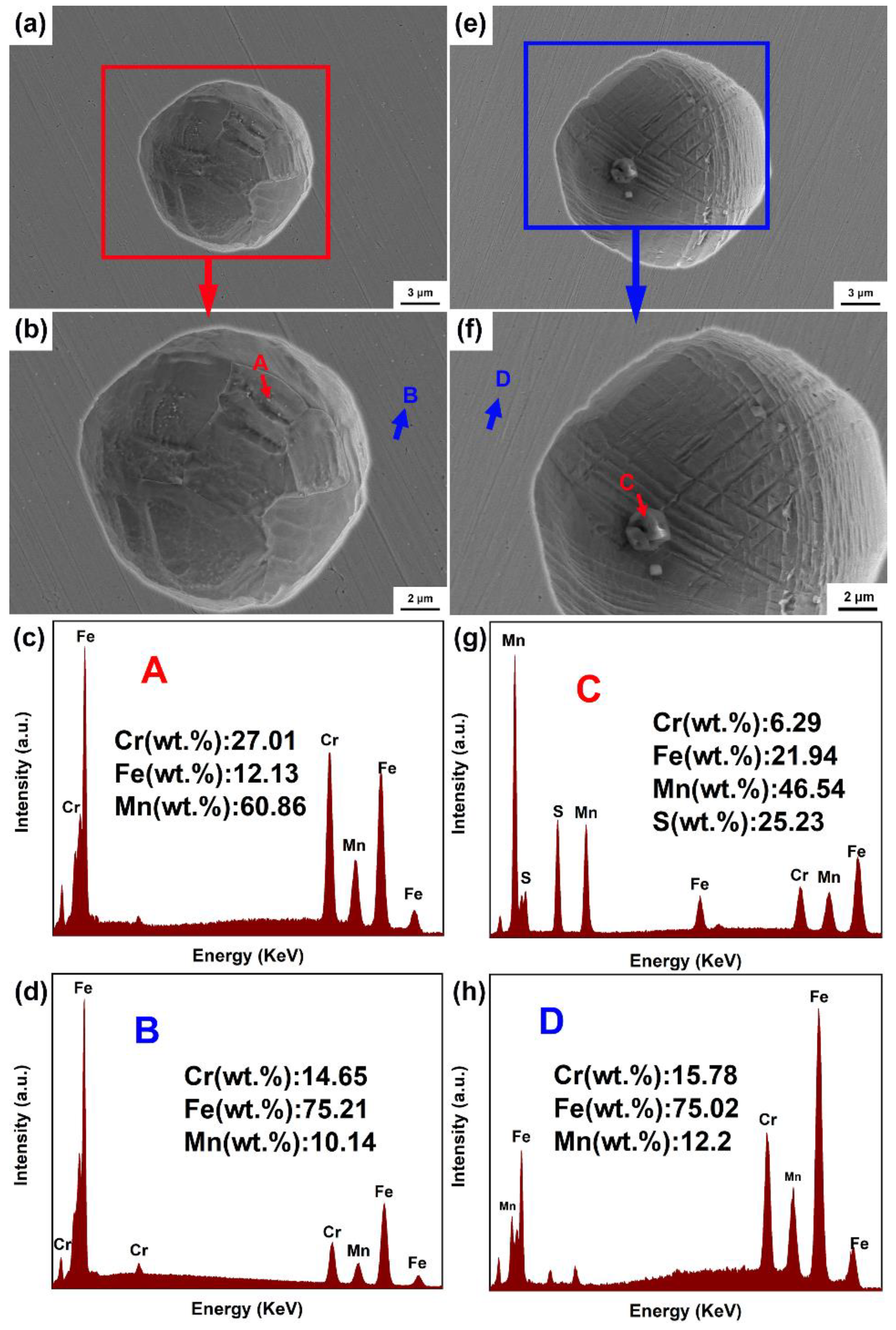
Figure 9 shows the detailed analysis of the typical pitting hole in the experimental MASS after the immersion test. For CR-MASS, it can be seen that the open and hemisphere pitting hole with a diameter of ~15 μm was filled with a large number of round particles (~15 nm in size) on its inner edge (Figure 9a,b). EDS analysis also shows that the Cr content of these particles are 27 wt.%, larger than that of the steel substrate. Combining with the results from Figure 2 and Figure 3, these round particles can be identified as Cr-rich M23C6 carbides. Several existed researches had reported that the Cr-rich M23C6 carbides often become the preferential sites for pitting of steel, either due to the Cr-depleted region around the interface between carbides and steel substrate [56], or their higher Volta potential than that of steel matrix [57]. Therefore, it is reasonable to infer that these fine M23C6 carbides initially existed in the steel substrate; when the corrosive solution encountered the steel surface, pitting initiated around the carbides and further propagated into the deep surface of the HR-MASS. Metal atom would be continuously dissolved and the carbides were therefore deposited on the edge of the pitting hole.
In Figure 9e, the detailed morphology of one stable pit on HR-MASS sample surface presents an open and hemispherical hole with diameter of 16.89 μm. Different from the pitting holes on CR-MASS, several kinked or crossed deformation bans were located inside the pits. In addition, two particles with sizes of 1.9 and 0.58 μm were located in the bottom of the hole, respectively. SEM-EDS analysis shows that these particles contain 46.54 wt.% of Mn and 25.23 wt.% of S, indicating that these particles should be the MnS inclusions. Based on the current results, the stable pits in CR-MASS could be ascribed to the local corrosion near the nano-sized Cr-rich M23C6 carbides, while the stable pitting holes on HR-MASS surface could be owed to the MnS inclusions.
4. Discussion
4.1. Formation of the Cr-Rich M23C6 Carbides in CR-MASS
Based on the current study, it is revealed that the main phases in both the CR- and HR-MASS are austenite and few “stress-induced” martensite ones. In addition, a large number of nano-sized M23C6 carbides was located in the austenitic grains of the CR-MASS, while no carbide existed in the HR-MASS. It had been reported by several researchers that the deformation during rolling can induce the precipitation of nano-sized carbides in several types of steel, including bearing steels (GCr15 steel) [42], high manganese austenitic Fe-Mn-C steels [58] and high-speed steel [43] which was usually defined as “deformation-induced carbide transformation (DICT)”. Zhou et al., claimed that the mechanism for DICT relied on the existence of “pre-deformation-induced defects” such as dislocations and/or twining, which could drop the decomposition temperature of carbides and even serve as the nucleation sites for carbides, inducing the precipitation of carbides inside the steel grains [43]. Considering the processing history of the experimental MASS, the CR-MASS was cold rolled after hot rolling. Moreover, the nano-sized M23C6 carbides mainly located near the dislocation lines or stacking faults (Figure 3); it can then be revealed that these carbides were initially nucleated near the local distortion of such deformation-induced defects, and then precipitated during rolling since the decomposition temperatures for these precipitates were decreased by these defects.
4.2. Pitting Mechanism of the CR- and HR-MASS
As researched by the current electrochemical measurements, the pitting resistance of HR-MASS was higher than that of the CR-MASS. The results from immersion tests revealed that the pitting initiation sites for the experimental MASS are different, that is, the stable pits in CR-MASS were mainly initiated around the Cr-rich M23C6 carbides, while inclusions such as MnS was the main defect for triggering the pitting for HR-MASS. In addition, Zhang et al., pointed out that the deformation band intersection can initiate the pitting in rolled 14Cr10Mn MASS [20]. In the current study, several stable pits in CR- and HR-MASS also located in the austenitic grains with high densities of deformation bands. It can then be inferred that the deformation bands were also the factor that induce pits in the experimental MASS. Since both the cold-rolled and hot-rolled MASS exhibited high densities of deformation bands, the mechanism for the difference of pitting performance between the CR- and HR-MASS must be reliant on the precipitation of Cr-rich M23C6 carbides.
It is widely acknowledged that the pits in stainless steels are prone to be initiated near the inclusions or carbides [28,59,60], which could be attributed to their higher Volta potential than that of the steel matrices, local distortion near them or the Cr-depleted region near the Cr-rich carbides [57]. In the current study, the nano-sized M23C6 carbides precipitated in CR-MASS contain higher Cr content than steel matrix. Although no obvious clue of Cr-depletion region was acquired in the current study due to the scale of the carbides being too small for analysis via EDS equipped either with SEM or TEM, several existed researches had successfully presented the Cr-depleted region near the Cr-rich M23C6 carbides [54,56,61,62]. Hence, it is reasonable to conclude that the nano-sized M23C6 carbides, which precipitated by the effect of DICT in CR-MASS, could induce Cr-depleted region around the boundaries between carbides and steel substrate, hampering the formation of passive film with better protectiveness. On the other hand, due to the fact that no carbides existed in HR-MASS, the passive film on HR-MASS surface would be thicker and more compact, which can hinder the pitting via corrosive anion (Cl− in the current work). When the dynamic conditions such as applied potential and immersing time increased, pits would be initiated around the inclusions or deformation bands.
5. Conclusions
(1) The main phase for the cold-rolled and hot-rolled Nickle saving MASS is austenite. In addition, small amounts of “stress-induced” martensite were also observed in the austenitic grains of the MASS. High densities of dislocations, stacking faults and deformation bands were located in both the CR- and HR-MASS. Particularly, Cr-rich M23C6 carbides were precipitated in the CR-MASS, while no carbides were observed in the HR-MASS.
(2) “Deformation-induced carbide transformation (DICT)” was proved to occur in the CR-MASS during cold-rolling, which could cause the pre-deformed defects such as dislocations or twinning, serving as the nucleation sites for carbides and catalyzing the precipitation of Cr-rich M23C6 carbides in the CR-MASS.
(3) HR-MASS exhibited higher pitting potential (Epit), larger effective capacitance (Ceff) and lower passive current density (ipass) than those of the CR-MASS, suggesting a better pitting resistance. Deformation bands seem to be the preferential sites of stable pitting for both CR- and HR-MASS. However, the Cr-rich M23C6 carbides also served as the pitting initiation for CR-MASS, while the MnS inclusions would be the initiation sites for HR-MASS when the dynamic factor (applied potential or immersion time) for pitting exceeded a critical value.
Author Contributions
S.L.: supervision, writing and editing. C.Z. (Chaoyang Zou): conceptualization, writing—original draft, graphics, and experiments. R.H., Y.Q., S.Q. and C.Z. (Chi Zhang): review and editing. All authors have read and agreed to the published version of the manuscript.
Funding
Siyuan Lu gratefully acknowledges the support from the National Natural Science Foundation of China (Grant No. 12172184), Key research and development program of Ningbo (2022Z050) and Posdoctoral research program of Zhejiang. Shuheng Qiu and Chi Zhang gratefully acknowledges the support from the the National Key Research and Development Program of China under Grant No. 2021YFB3803004, in part by the National Natural Science Foundation of China Youth Science Foundation under Grant No. 52107062, in part by Ningbo “Technology Innovation 2025” Major Project under Grant No. 2019B10077, 2020Z069, 2019B10070.
Institutional Review Board Statement
Not applicable.
Informed Consent Statement
Not applicable.
Data Availability Statement
The raw data required to reproduce these findings are available upon request from the corresponding author (Siyuan Lu).
Conflicts of Interest
The authors declare no conflict of interest.
References
- Backhouse, A.; Baddoo, N. Recent developments of stainless steels in structural applications. CE/Papers 2021, 4, 2349–2355. [Google Scholar] [CrossRef]
- Hariharan, K.; Balachandran, G.; Prasad, M.S. Application of Cost-Effective Stainless Steel for Automotive Components. Mater. Manuf. Process. 2009, 24, 1442–1452. [Google Scholar] [CrossRef]
- Hofmann, H.; Mattissen, D.; Schaumann, T.W. Advanced Cold Rolled Steels for Automotive Applications. Steel Res. Int. 2009, 80, 22–28. [Google Scholar] [CrossRef]
- De Vecchis, R.R.; Wang, X.; Sridar, S.; Wang, Z.; Pataky, G.J.; Xiong, W. Introducing Heusler intermetallics for synergic effect of grain refinement and precipitation strengthening in high-strength low-alloy steels. J. Alloy. Compd. 2022, 904, 163885. [Google Scholar] [CrossRef]
- Taylor, T.; Clough, A. Critical review of automotive hot-stamped sheet steel from an industrial perspective. Mater. Sci. Technol. 2017, 34, 809–861. [Google Scholar] [CrossRef]
- Boes, J.; Röttger, A.; Theisen, W. Microstructure and properties of high-strength C+N austenitic stainless steel processed by laser powder bed fusion. Addit. Manuf. 2020, 32, 101081. [Google Scholar] [CrossRef]
- Hu, L.; Peng, H.; Baker, I.; Li, L.; Zhang, W.; Ngai, T. Characterization of high-strength high-nitrogen austenitic stainless steel synthesized from nitrided powders by spark plasma sintering. Mater. Charact. 2019, 152, 76–84. [Google Scholar] [CrossRef]
- Kim, D.G.; Jo, Y.H.; Song, T.; Kim, H.S.; Lee, B.-J.; Sohn, S.S.; Lee, S. Excellent strength-ductility combination of multi-layered sheets composed of high-strength V10Cr10Fe50Co30 high entropy alloy and 304 austenitic stainless steel. Mater. Sci. Eng. A 2021, 823, 141727. [Google Scholar] [CrossRef]
- Kim, Y.-K.; Lee, K.-A. Direct energy deposition of high strength austenitic stainless steel matrix nanocomposite with superior ductility: Microstructure, tensile properties, and deformation behavior. Mater. Charact. 2021, 179, 111358. [Google Scholar] [CrossRef]
- Schmitt, J.-H.; Iung, T. New developments of advanced high-strength steels for automotive applications. C. R. Phys. 2018, 19, 641–656. [Google Scholar] [CrossRef]
- Vukkum, V.; Gupta, R. Review on corrosion performance of laser powder-bed fusion printed 316L stainless steel: Effect of processing parameters, manufacturing defects, post-processing, feedstock, and microstructure. Mater. Des. 2022, 221, 110874. [Google Scholar] [CrossRef]
- Cheng, M.; He, P.; Lei, L.; Tan, X.; Wang, X.; Sun, Y.; Li, J.; Jiang, Y. Comparative studies on microstructure evolution and corrosion resistance of 304 and a newly developed high Mn and N austenitic stainless steel welded joints. Corros. Sci. 2021, 183, 109338. [Google Scholar] [CrossRef]
- Li, J.; Li, H.; Liang, Y.; Liu, P.; Yang, L.; Wang, Y. Effects of heat input and cooling rate during welding on intergranular corrosion behavior of high nitrogen austenitic stainless steel welded joints. Corros. Sci. 2020, 166, 108445. [Google Scholar] [CrossRef]
- Hu, L.; Ngai, T.; Peng, H.; Li, L.; Zhou, F.; Peng, Z. Microstructure and Properties of Porous High-N Ni-Free Austenitic Stainless Steel Fabricated by Powder Metallurgical Route. Materials 2018, 11, 1058. [Google Scholar] [CrossRef] [Green Version]
- Li, S.; Zhang, C.; Lu, J.; Chen, R.; Chen, D.; Cui, G. A review of progress on high nitrogen austenitic stainless-steel research. Mater. Express 2021, 11, 1901–1925. [Google Scholar] [CrossRef]
- Di Schino, A.; Kenny, J.M.; Mecozzi, M.G.; Barteri, M. Development of high nitrogen, low nickel, 18%Cr austenitic stainless steels. J. Mater. Sci. 2000, 35, 4803–4808. [Google Scholar] [CrossRef]
- Kim, Y.H.; Kim, K.Y.; Lee, Y.D. Nitrogen-Alloyed, Metastable Austenitic Stainless Steel for Automotive Structural Applications. Mater. Manuf. Process. 2004, 19, 51–59. [Google Scholar] [CrossRef]
- Wállen, B.; Liljas, M.; Stenvall, P. A new high-molybdenum, high-nitrogen stainless steel. Mater. Des. 1992, 13, 329–333. [Google Scholar] [CrossRef]
- Lo, K.H.; Shek, C.H.; Lai, J.K.L. Recent developments in stainless steels. Mater. Sci. Eng. R Rep. 2009, 65, 39–104. [Google Scholar] [CrossRef]
- Zhang, Y.; Li, M.; Bi, H.; Chen, D.; Gu, J.; Chang, E. Mechanical properties of cold-rolled metastable Cr–Mn–Ni–N austenitic stainless steel at low ambient temperature. Mater. Sci. Eng. A 2019, 759, 224–233. [Google Scholar] [CrossRef]
- Fukumoto, S.; Oikawa, Y.; Tsuge, S.; Nomoto, S. Prediction of σ Phase Formation in Fe–Cr–Ni–Mo–N Alloys. ISIJ Int. 2010, 50, 445–449. [Google Scholar] [CrossRef] [Green Version]
- Hao, Y.-s.; Li, J.; Liu, W.-c.; Zhang, W.-n.; Liu, Z.-y. On microstructure characterization of Fe–Cr–Ni–Mo–N super-austenitic stainless steel during hot deformation. J. Iron Steel Res. Int. 2019, 26, 1080–1087. [Google Scholar] [CrossRef]
- Pu, E.; Zheng, W.; Song, Z.; Feng, H.; Zhu, Y. Characterization of Hot Deformation Behavior of a Fe-Cr-Ni-Mo-N Superaustenitic Stainless Steel Using Dynamic Materials Modeling. J. Mater. Eng. Perform. 2017, 26, 1424–1432. [Google Scholar] [CrossRef]
- Tao, X.; Li, X.; Dong, H.; Matthews, A.; Leyland, A. Evaluation of the sliding wear and corrosion performance of triode-plasma nitrided Fe-17Cr-20Mn-0.5N high-manganese and Fe-19Cr-35Ni-1.2Si high-nickel austenitic stainless steels. Surf. Coat. Technol. 2021, 409, 126890. [Google Scholar] [CrossRef]
- Vats, V.; Baskaran, T.; Arya, S.B. Tribo-corrosion study of nickel-free, high nitrogen and high manganese austenitic stainless steel. Tribol. Int. 2018, 119, 659–666. [Google Scholar] [CrossRef]
- Niederhofer, P.; Richrath, L.; Huth, S.; Theisen, W. Influence of conventional and powder-metallurgical manufacturing on the cavitation erosion and corrosion of high interstitial CrMnCN austenitic stainless steels. Wear 2016, 360–361, 67–76. [Google Scholar] [CrossRef]
- Shi, F.; Tian, P.; Jia, N.; Ye, Z.; Qi, Y.; Liu, C.; Li, X. Improving intergranular corrosion resistance in a nickel-free and manganese-bearing high-nitrogen austenitic stainless steel through grain boundary character distribution optimization. Corros. Sci. 2016, 107, 49–59. [Google Scholar] [CrossRef]
- Frankel, G.S. Pitting Corrosion of Metals: A Review of the Critical Factors. J. Electrochem. Soc. 1998, 145, 2186–2198. [Google Scholar] [CrossRef]
- Krawczyk, B.; Cook, P.; Hobbs, J.; Engelberg, D.L. Corrosion Behavior of Cold Rolled Type 316L Stainless Steel in HCl-Containing Environments. Corrosion 2017, 73, 1346–1358. [Google Scholar] [CrossRef]
- Krüger, L.; Wolf, S.; Martin, U.; Martin, S.; Scheller, P.R.; Jahn, A.; Weiß, A. The influence of martensitic transformation on mechanical properties of cast high alloyed CrMnNi-steel under various strain rates and temperatures. J. Phys. Conf. Ser. 2010, 240, 012098. [Google Scholar] [CrossRef]
- Han, D.-X.; Du, L.-X.; Dong, Y.; Misra, R.D.K. The Impact of Deformation Conditions on Divorced Eutectoid Transformation in Bearing Steels. Steel Res. Int. 2018, 90, 1800384. [Google Scholar] [CrossRef]
- Kumar, B.R.; Singh, R.; Mahato, B.; De, P.; Bandyopadhyay, N.; Bhattacharya, D. Effect of texture on corrosion behavior of AISI 304L stainless steel. Mater. Charact. 2005, 54, 141–147. [Google Scholar] [CrossRef]
- Mudali, U.K.; Shankar, P.; Ningshen, S.; Dayal, R.; Khatak, H.; Raj, B. On the pitting corrosion resistance of nitrogen alloyed cold worked austenitic stainless steels. Corros. Sci. 2002, 44, 2183–2198. [Google Scholar] [CrossRef]
- Zhang, Y.; Li, M.; Bi, H. The mechanism of pitting initiation and propagation at deformation bands intersection of cold-rolled metastable stainless steel in acidic ferric chloride solution. J. Mater. Sci. 2019, 54, 14914–14925. [Google Scholar] [CrossRef]
- Franck, F.J.; Tambuyser, P.; Zubani, I. X-ray powder diffraction evidence for the incorporation of W and Mo into M23C6 extracted from high-temperature alloys. J. Mater. Sci. 1982, 17, 3057–3065. [Google Scholar] [CrossRef]
- Lu, S.-Y.; Yao, K.-F.; Chen, Y.-B.; Wang, M.-H.; Shao, Y.; Ge, X.-Y. Effects of austenitizing temperature on the microstructure and electrochemical behavior of a martensitic stainless steel. J. Appl. Electrochem. 2015, 45, 375–383. [Google Scholar] [CrossRef]
- Cao, C.; Fu, J.; Tong, T.; Hao, Y.; Gu, P.; Hao, H.; Peng, L. Intermediate-Temperature Creep Deformation and Microstructural Evolution of an Equiatomic FCC-Structured CoCrFeNiMn High-Entropy Alloy. Entropy 2018, 20, 960. [Google Scholar] [CrossRef] [Green Version]
- Fukunaga, T.; Kaneko, K.; Kawano, R.; Ueda, K.; Yamada, K.; Nakada, N.; Kikuchi, M.; Barnard, J.S.; Midgley, P.A. Formation of Intergranular M23C6 in Sensitized Type-347 Stainless Steel. ISIJ Int. 2014, 54, 148–152. [Google Scholar] [CrossRef] [Green Version]
- Kwon, H.; Moon, J.; Bae, J.W.; Park, J.M.; Son, S.; Do, H.-S.; Lee, B.-J.; Kim, H.S. Precipitation-driven metastability engineering of carbon-doped CoCrFeNiMo medium-entropy alloys at cryogenic temperature. Scr. Mater. 2020, 188, 140–145. [Google Scholar] [CrossRef]
- Zhang, Y.; Li, M.; Bi, H.; Gu, J.; Chen, D.; Chang, E.; Zhang, W. Martensite transformation behavior and mechanical properties of cold-rolled metastable Cr-Mn-Ni-N austenitic stainless steels. Mater. Sci. Eng. A 2018, 724, 411–420. [Google Scholar] [CrossRef]
- Han, D.-X.; Du, L.-X.; Yao, C.-X.; Misra, R.D.K. The Evolution of Deformation-Induced Carbides during Divorced Eutectoid Transformation in GCr15 Steels. J. Mater. Eng. Perform. 2019, 28, 5277–5288. [Google Scholar] [CrossRef]
- Han, D.-X.; Du, L.-X.; Zhang, B.; Misra, R.D.K. Effect of deformation on deformation-induced carbides and spheroidization in bearing steel. J. Mater. Sci. 2018, 54, 2612–2627. [Google Scholar] [CrossRef]
- Zhou, X.; Zheng, Z.; Zhang, W.; Fang, F.; Tu, Y.; Jiang, J. Deformation-Induced Carbide Transformation in M2 High-Speed Steel. Met. Mater. Trans. A 2019, 51, 568–573. [Google Scholar] [CrossRef]
- Cui, Z.; Wang, L.; Ni, H.; Hao, W.; Man, C.; Chen, S.; Wang, X.; Liu, Z.; Li, X. Influence of temperature on the electrochemical and passivation behavior of 2507 super duplex stainless steel in simulated desulfurized flue gas condensates. Corros. Sci. 2017, 118, 31–48. [Google Scholar] [CrossRef]
- Khalaj, G.; Pouraliakbar, H.; Arab, N.; Nazerfakhari, M. Correlation of passivation current density and potential by using chemical composition and corrosion cell characteristics in HSLA steels. Measurement 2015, 75, 5–11. [Google Scholar] [CrossRef]
- King, A.; Birbilis, N.; Scully, J. Accurate Electrochemical Measurement of Magnesium Corrosion Rates; a Combined Impedance, Mass-Loss and Hydrogen Collection Study. Electrochim. Acta 2014, 121, 394–406. [Google Scholar] [CrossRef]
- Duan, Z.; Man, C.; Dong, C.; Cui, Z.; Kong, D.; Wang, L.; Wang, X. Pitting behavior of SLM 316L stainless steel exposed to chloride environments with different aggressiveness: Pitting mechanism induced by gas pores. Corros. Sci. 2020, 167, 108520. [Google Scholar] [CrossRef]
- Chen, W.-C.; Wen, T.-C.; Teng, H. Polyaniline-deposited porous carbon electrode for supercapacitor. Electrochim. Acta 2003, 48, 641–649. [Google Scholar] [CrossRef]
- Dong, Z.H.; Shi, W.; Ruan, H.M.; Zhang, G.A. Heterogeneous corrosion of mild steel under SRB-biofilm characterised by electrochemical mapping technique. Corros. Sci. 2011, 53, 2978–2987. [Google Scholar] [CrossRef]
- Macdonald, D.D. Reflections on the history of electrochemical impedance spectroscopy. Electrochim. Acta 2006, 51, 1376–1388. [Google Scholar] [CrossRef]
- Hsu, C.H.; Mansfeld, F. Technical Note: Concerning the Conversion of the Constant Phase Element Parameter Y0 into a Capacitance. Corrosion 2001, 57, 747–748. [Google Scholar] [CrossRef]
- Hirschorn, B.; Orazem, M.E.; Tribollet, B.; Vivier, V.; Frateur, I.; Musiani, M. Determination of effective capacitance and film thickness from constant-phase-element parameters. Electrochim. Acta 2010, 55, 6218–6227. [Google Scholar] [CrossRef]
- Fattah-Alhosseini, A.; Golozar, M.; Saatchi, A.; Raeissi, K. Effect of solution concentration on semiconducting properties of passive films formed on austenitic stainless steels. Corros. Sci. 2010, 52, 205–209. [Google Scholar] [CrossRef]
- Man, C.; Dong, C.; Cui, Z.; Xiao, K.; Yu, Q.; Li, X. A comparative study of primary and secondary passive films formed on AM355 stainless steel in 0.1 M NaOH. Appl. Surf. Sci. 2018, 427, 763–773. [Google Scholar] [CrossRef]
- Li, X.; Wang, L.; Fan, L.; Zhong, M.; Cheng, L.; Cui, Z. Understanding the effect of fluoride on corrosion behavior of pure titanium in different acids. Corros. Sci. 2021, 192, 109812. [Google Scholar] [CrossRef]
- Bonagani, S.K.; Bathula, V.; Kain, V. Influence of tempering treatment on microstructure and pitting corrosion of 13 wt.% Cr martensitic stainless steel. Corros. Sci. 2018, 131, 340–354. [Google Scholar] [CrossRef]
- Liu, C.; Revilla, R.I.; Liu, Z.; Zhang, D.; Li, X.; Terryn, H. Effect of inclusions modified by rare earth elements (Ce, La) on localized marine corrosion in Q460NH weathering steel. Corros. Sci. 2017, 129, 82–90. [Google Scholar] [CrossRef]
- Shabashov, V.A.; Korshunov, L.G.; Zamatovskii, A.E.; Litvinov, A.V.; Sagaradze, V.; Kositsyna, I.I. Deformation-induced dissolution of carbides of the Me(V, Mo)-C Type in high-manganese steels upon the friction effect. Phys. Met. Met. 2012, 113, 914–921. [Google Scholar] [CrossRef]
- Ryan, M.P.; Williams, D.E.; Chater, R.J.; Hutton, B.M.; McPhail, D.S. Why stainless steel corrodes. Nature 2002, 415, 770–774. [Google Scholar] [CrossRef]
- Tokuda, S.; Muto, I.; Sugawara, Y.; Hara, N. Pit initiation on sensitized Type 304 stainless steel under applied stress: Correlation of stress, Cr-depletion, and inclusion dissolution. Corros. Sci. 2020, 167, 108506. [Google Scholar] [CrossRef]
- Bruemmer, S.M.; Chariot, L.A.; Arey, B.W. Sensitization Development in Austenitic Stainless Steel: Correlation between STEM-EDS and EPR Measurements. Corrosion 1988, 44, 328–333. [Google Scholar] [CrossRef]
- Zhao, Y.; Liu, W.; Zhang, T.; Sun, Z.; Wang, Y.; Fan, Y.; Dong, B. Assessment of the correlation between M23C6 precipitates and pitting corrosion resistance of 0Cr13 martensitic stainless steel. Corros. Sci. 2021, 189, 109580. [Google Scholar] [CrossRef]
Figure 1.
Electron back scattered diffraction (EBSD) micrographs of the experimental steels: (a,b) present the band contrast micrograph of CR-MASS and HR-MASS, respectively; (c,d) display the color-coded phase maps (austenite: green, martensite: red) in accordance to (a,b), respectively.
Figure 1.
Electron back scattered diffraction (EBSD) micrographs of the experimental steels: (a,b) present the band contrast micrograph of CR-MASS and HR-MASS, respectively; (c,d) display the color-coded phase maps (austenite: green, martensite: red) in accordance to (a,b), respectively.
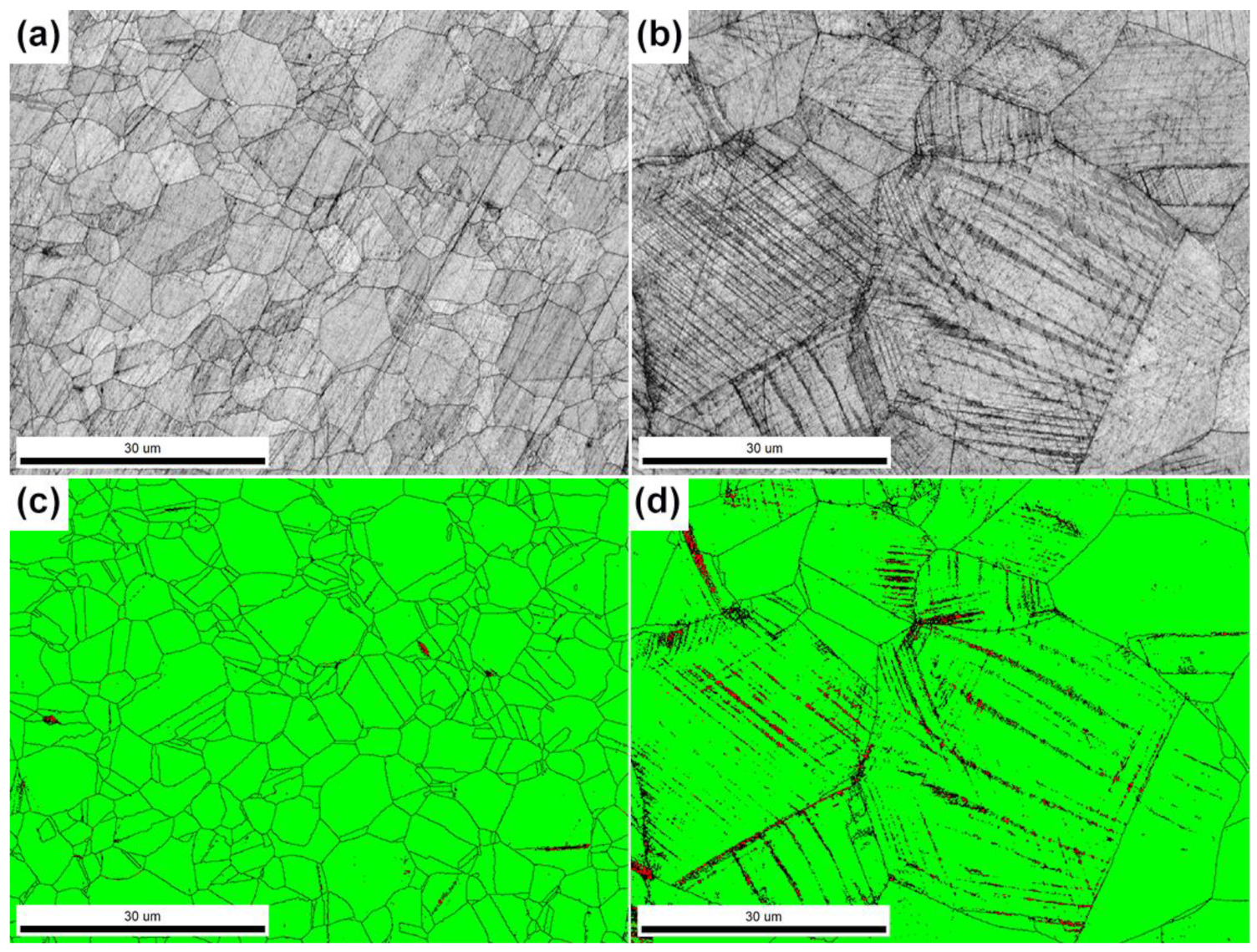
Figure 2.
The metallographic images of (a) CR-MASS, and (b) HR-MASS; scanning electron micrographs (SEM) of the experimental MASS: (c) CR-MASS and (d) HR-MASS; (e) shows the magnified images of the white frame in (c); (f,g) illustrate the chemical composition of point A and B in (e), respectively.
Figure 2.
The metallographic images of (a) CR-MASS, and (b) HR-MASS; scanning electron micrographs (SEM) of the experimental MASS: (c) CR-MASS and (d) HR-MASS; (e) shows the magnified images of the white frame in (c); (f,g) illustrate the chemical composition of point A and B in (e), respectively.

Figure 3.
Transmission electron microscopy (TEM) images of the CR-MASS: (a) bright-field image; (b) the magnified image of the area marked as red frame in (a), (c) corresponding dark-field image of (b), and (d) the selected-area electron diffraction pattern (SADP) of M23C6 carbides and austenite. (e,f) separately indicate the chemical composition of steel substrate (point A in (b)) and the M23C6 carbides (point B in (b)).
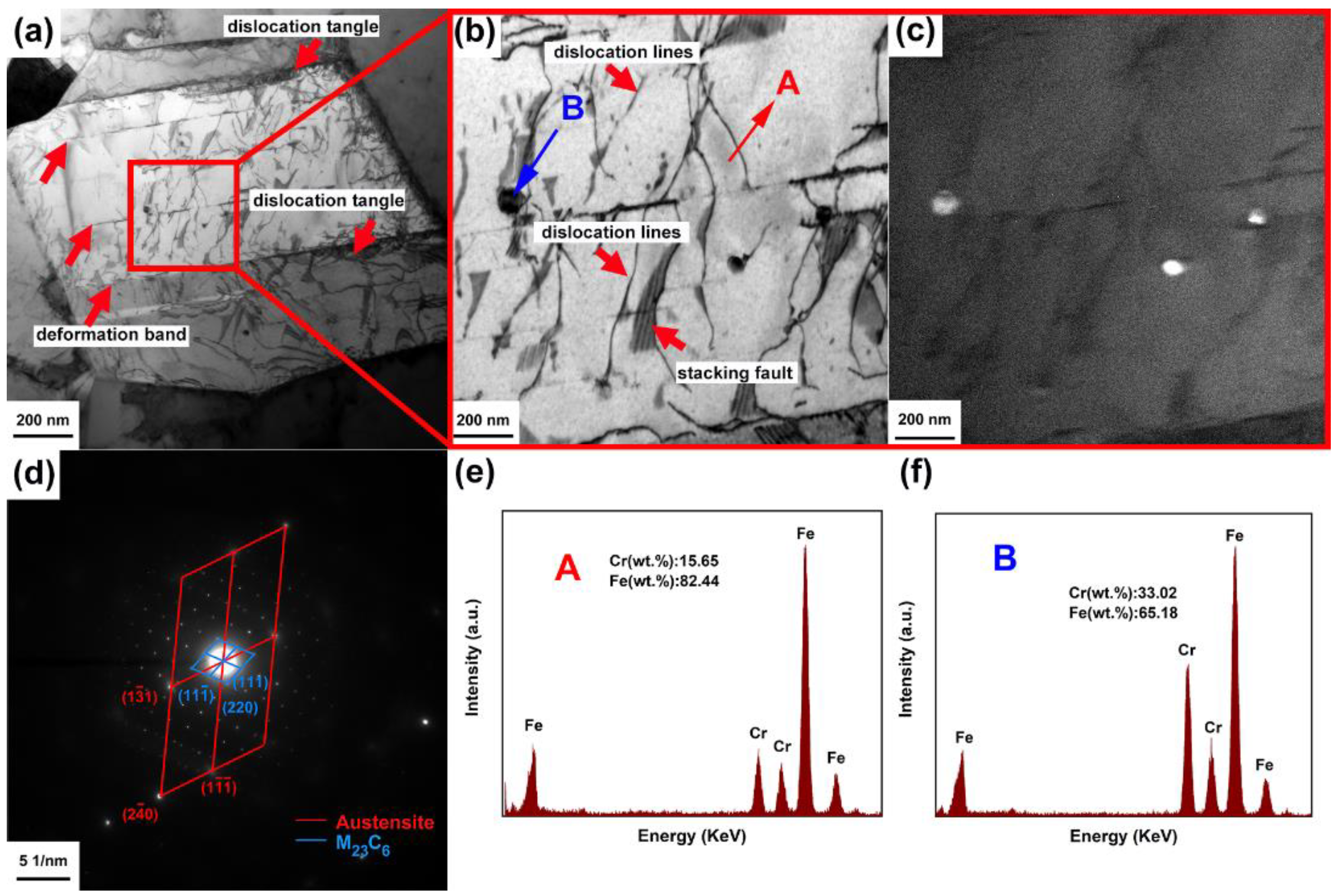
Figure 4.
TEM images of (a) HR-MASS, and (b) shows the magnified image of the area marked by blue box in (a). (c) shows the deformation induced martensite (DIM) in austenite grain of HR-MASS, (d,e) is the magnified bright-field and dark-field images of the area marked red frame in (c), respectively. (f) is the corresponding selected-area diffraction pattern of (e). (g,h) show the chemical composition of steel substrate (point A in (d)) and DIM (point B in (d)) for HR-MASS.
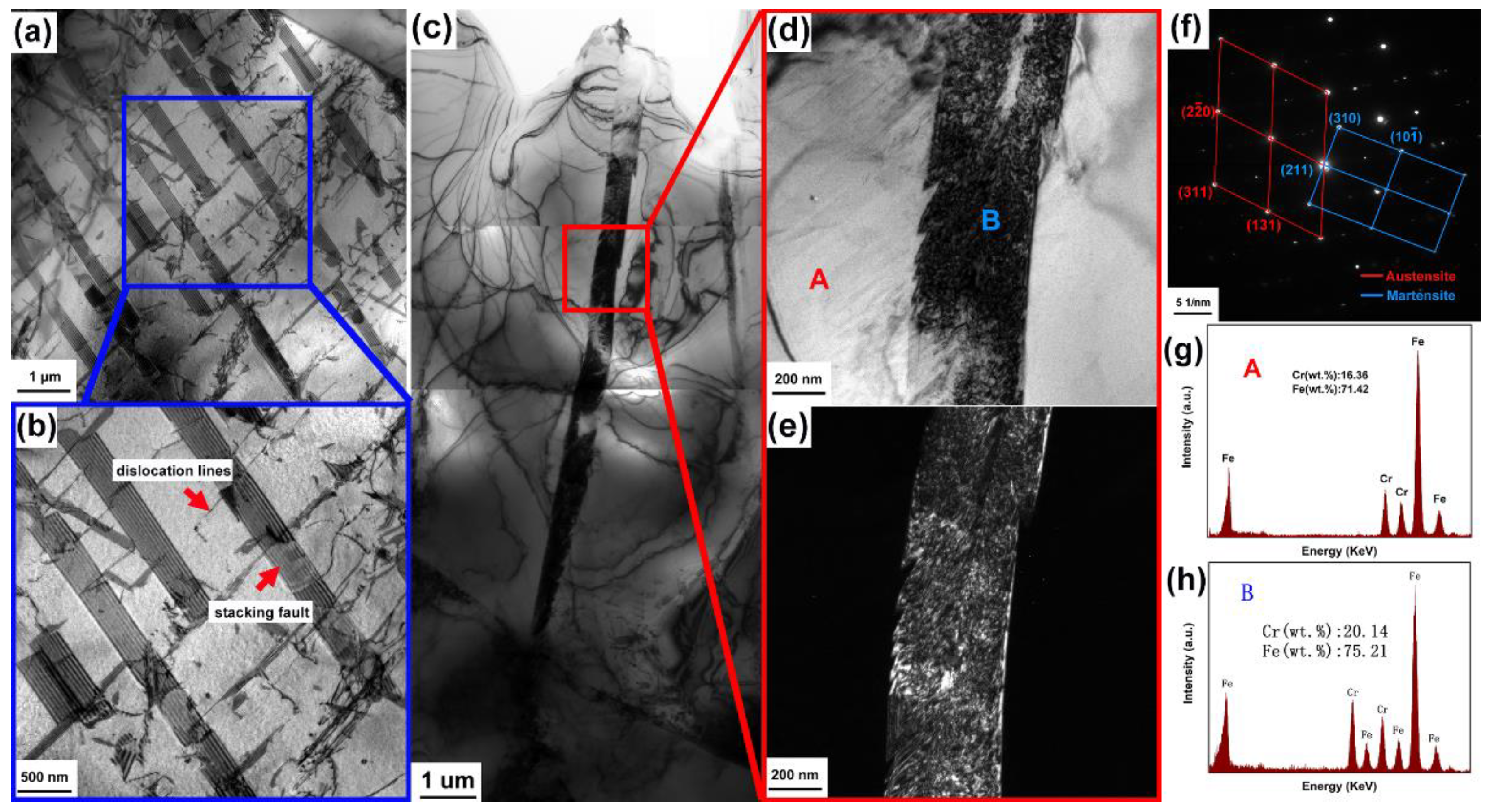
Figure 5.
Results of electrochemical measurements: (a) open circuit potentials (OCPs) of the experimental MASS, (b) potentiodynamic polarization curves of the experimental MASS and (c) the cumulative probability distribution of pitting potentials (Epit) of the experimental MASS. All tests were conducted in 3.5 wt.% NaCl aqueous solution at ambient temperature (~25 °C).
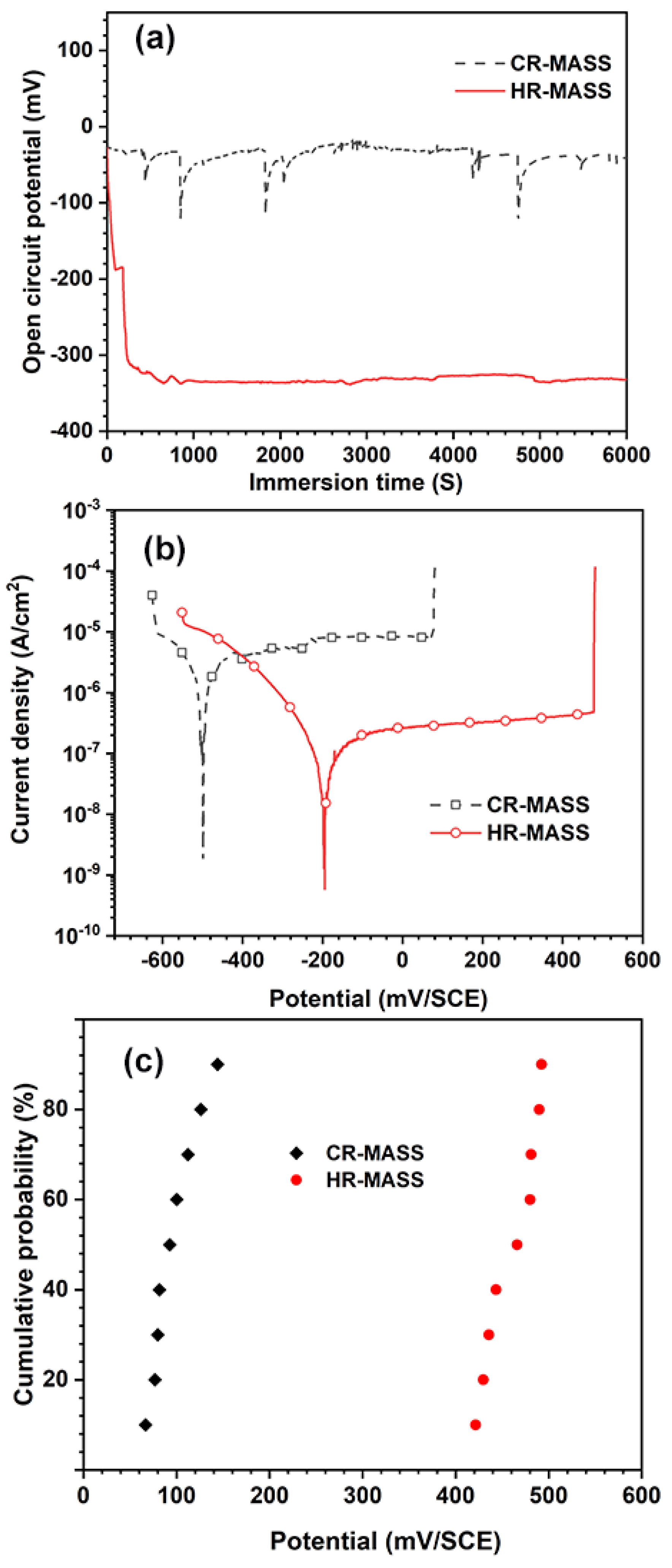
Figure 6.
EIS spectrum of the experimental MASS in 3.5 wt.% NaCl aqueous solution at room temperature (~25 °C): (a) Nyquist plots, (b) Bode plots.
Figure 6.
EIS spectrum of the experimental MASS in 3.5 wt.% NaCl aqueous solution at room temperature (~25 °C): (a) Nyquist plots, (b) Bode plots.
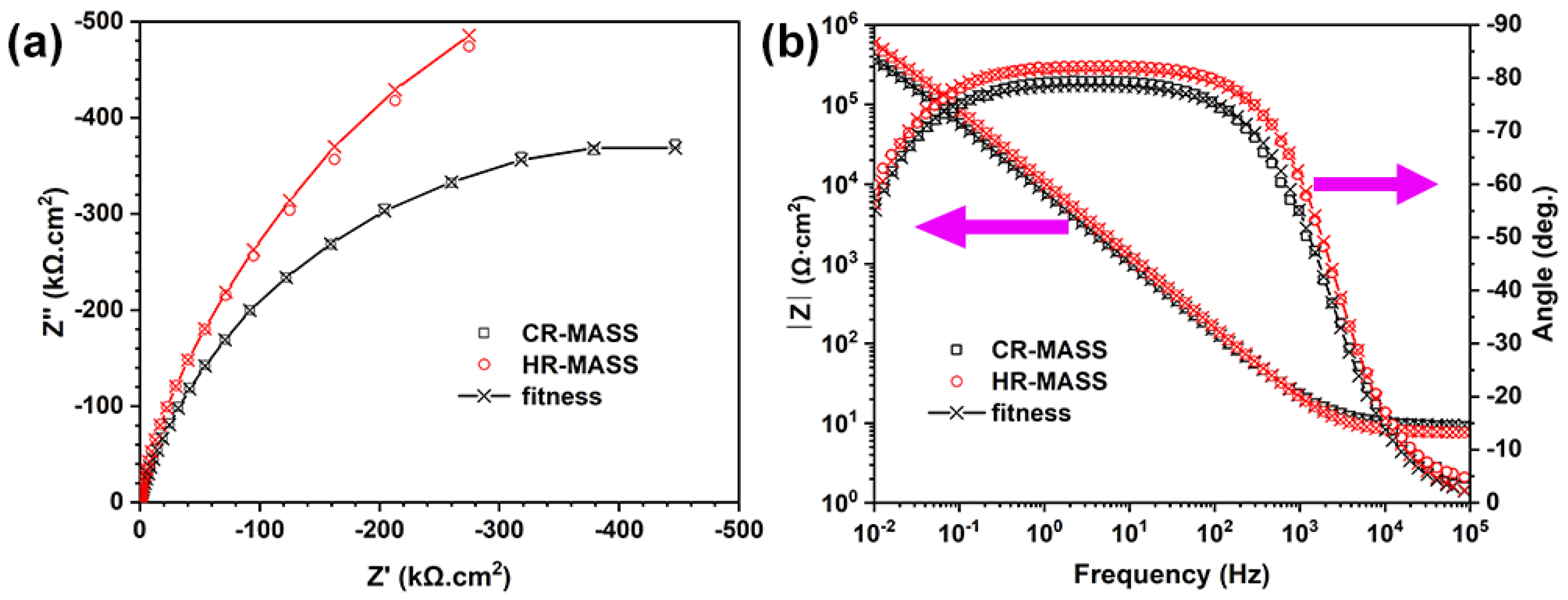
Figure 7.
Equivalent circuits used for fitting the experimental impedance data.
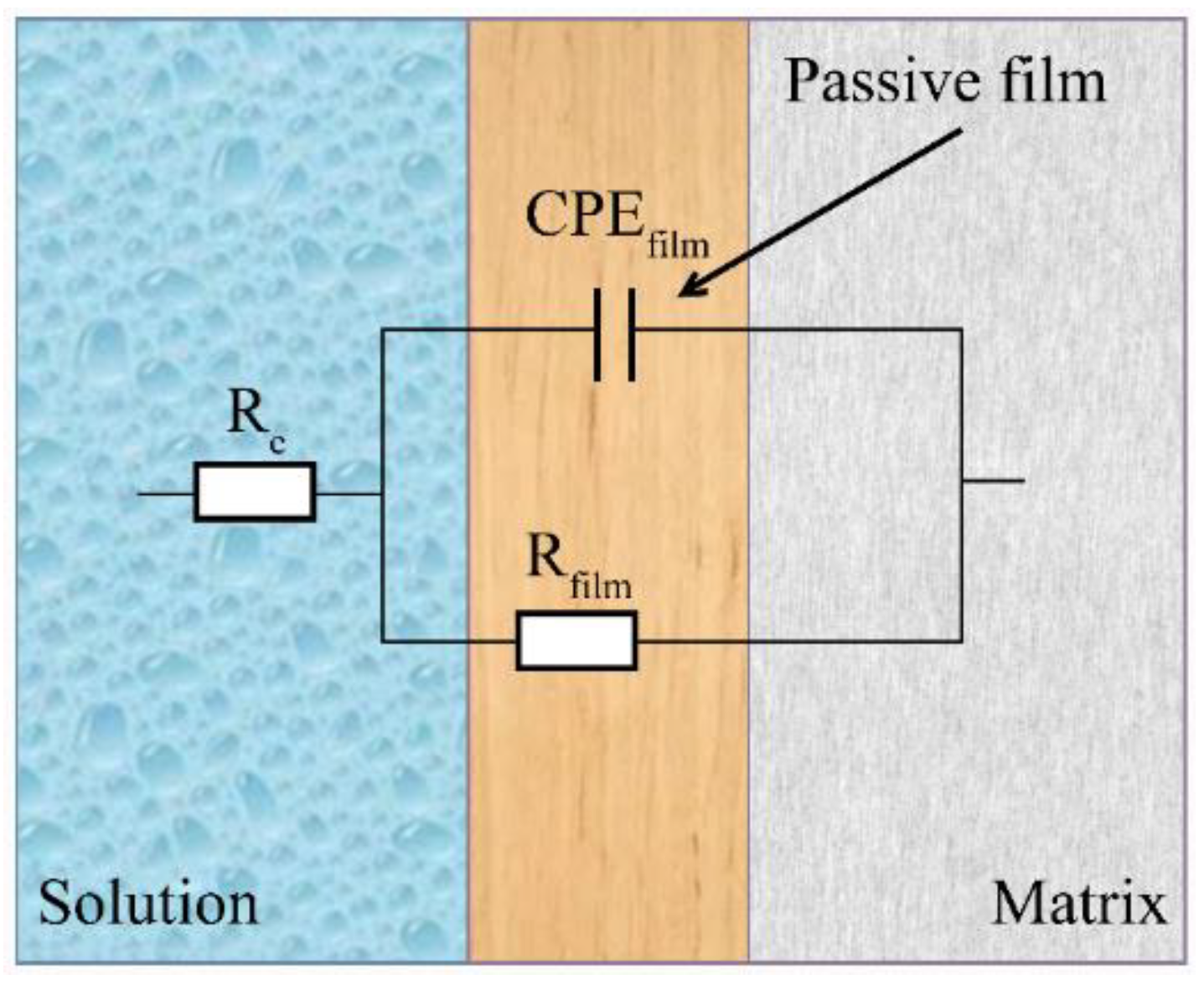
Figure 8.
The evolution of pitting morphologies of the experimental MASS after immersion in acidic ferric chloride solution for different time intervals of 0, 1, 1.5, 2 and 4 min via optical microscopy: (a–e) CR-MASS, (f–j) HR-MASS. The observation time intervals are listed in each micrograph.
Figure 8.
The evolution of pitting morphologies of the experimental MASS after immersion in acidic ferric chloride solution for different time intervals of 0, 1, 1.5, 2 and 4 min via optical microscopy: (a–e) CR-MASS, (f–j) HR-MASS. The observation time intervals are listed in each micrograph.

Figure 9.
Detailed analysis of the pits in the experimental MASS after immersion test via SEM and EDS: (a,e) are the micrograph of one typical pit in CR-MASS and HR-MASS, respectively; (b,f) show the magnified image of the area marked by red frame in (a) and blue frame in (e); (c,d) separately show the EDS results of steel substrate (point B in (b)) and M23C6 carbides (point A in (b)); (g,h) respectively, display the chemical composition of MnS (point C in (f)) and steel substrate (point D in (f)).

Table 1.
Chemical composition of the metastable austenitic stainless steel (MASS).
| Steel | Chemical Composition, wt.% | ||||||||
|---|---|---|---|---|---|---|---|---|---|
| C | Ni | Cr | Mn | Cu | Si | P | S | N | |
| MASS | 0.015 | 1.025 | 13.2 | 9.15 | 0.25 | 0.5 | 0.023 | 0.003 | 0.145 |
Table 2.
The electrochemical parameters from OCP and PDP measurements of the experimental MSSs. OCP: open circuit potential, ipass: passive current density, Ecorr: corrosion potential, Epit: pitting potential.
Table 2.
The electrochemical parameters from OCP and PDP measurements of the experimental MSSs. OCP: open circuit potential, ipass: passive current density, Ecorr: corrosion potential, Epit: pitting potential.
| Sample | OCP (mV/SCE) | ipass (μA/cm2) | Ecorr (mV/SCE) | Epit (mV/SCE) |
|---|---|---|---|---|
| CR-MASS | −57.64 ± 8.24 | 8.37 ± 0.15 | −173.36 ± 18.96 | 105.42 ± 16.34 |
| HR-MASS | −331.82 ± 6.08 | 3.74 ± 0.08 | −451.68 ± 9.74 | 460.40 ± 8.59 |
Table 3.
Fitting results of the EIS parameters for the experimental MASS according to the equivalent circuits.
Table 3.
Fitting results of the EIS parameters for the experimental MASS according to the equivalent circuits.
| Specimen | Re (Ω·cm2) ± 0.5% | CPEf | Rf (kΩ·cm2) ± 2.6% | |
|---|---|---|---|---|
| Qf (MΩ−1·cm−2·sα) ± 1.5% | αf ± 0.3% | |||
| CR-MASS | 4.13 | 23.34 | 0.92 | 607.87 |
| HR-MASS | 9.34 | 16.10 | 0.91 | 1640.11 |
Table 4.
The calculated values of the effective capacitance (Cf) and passive film thickness (df) of the experimental MASS based on EIS results.
Table 4.
The calculated values of the effective capacitance (Cf) and passive film thickness (df) of the experimental MASS based on EIS results.
| Sample | Cf (μF·cm−2) | df (nm) |
|---|---|---|
| CR-MASS | 53.60 | 2.58 |
| HR-MASS | 44.07 | 3.13 |
Publisher’s Note: MDPI stays neutral with regard to jurisdictional claims in published maps and institutional affiliations. |
© 2022 by the authors. Licensee MDPI, Basel, Switzerland. This article is an open access article distributed under the terms and conditions of the Creative Commons Attribution (CC BY) license (https://creativecommons.org/licenses/by/4.0/).
Share and Cite
MDPI and ACS Style
Lu, S.; Zou, C.; Huang, R.; Qiu, Y.; Qiu, S.; Zhang, C. Pitting Performance of Cold- and Hot-Rolled Nickel-Saving High-Strength Metastable Austenitic Stainless Steel. Coatings 2022, 12, 1869. https://doi.org/10.3390/coatings12121869
AMA Style
Lu S, Zou C, Huang R, Qiu Y, Qiu S, Zhang C. Pitting Performance of Cold- and Hot-Rolled Nickel-Saving High-Strength Metastable Austenitic Stainless Steel. Coatings. 2022; 12(12):1869. https://doi.org/10.3390/coatings12121869
Chicago/Turabian StyleLu, Siyuan, Chaoyang Zou, Riqing Huang, Yiming Qiu, Shuheng Qiu, and Chi Zhang. 2022. "Pitting Performance of Cold- and Hot-Rolled Nickel-Saving High-Strength Metastable Austenitic Stainless Steel" Coatings 12, no. 12: 1869. https://doi.org/10.3390/coatings12121869
Note that from the first issue of 2016, this journal uses article numbers instead of page numbers. See further details here.