Article

Surface Mechanical Properties and Micro-Structure Evolution of 7075 Aluminum Alloy Sheet for 2-Dimension Ellipse Ultrasonic Vibration Incremental Forming: A Pretreatment for Laser Shock Peening

College of Mechanical Engineering, Xi’an University of Science and Technology, Xi’an 710054, China
*
Author to whom correspondence should be addressed.
Coatings 2022, 12(12), 1914; https://doi.org/10.3390/coatings12121914
Submission received: 5 November 2022 / Revised: 28 November 2022 / Accepted: 4 December 2022 / Published: 7 December 2022
(This article belongs to the Special Issue Laser-Assisted Coating Techniques and Surface Modifications)

Abstract

:
In this paper, a composite technique of ultrasonic incremental forming and laser shock peeing is proposed. The former process is mainly used for the manufacturing of complex-shaped sheet and strengthening coating that is prepared for subsequent laser treatment. The latter is applied for secondary surface reinforcement with ultra-high energy. This work focused on the novel ultrasonic incremental forming method and its effects on surface mechanical properties and micro-structure of a 7075 aluminum alloy. First, a kind of 2-dimension ellipse ultrasonic vibration incremental forming process and the unique double-mechanism method of sectionalized cooperative control of plastic deformation and mechanical performance were designed. Second, the single-point incremental forming, the longitudinal ultrasonic vibration incremental forming, and the 2 dimension ellipse ultrasonic vibration incremental forming were performed for the manufacture of conical components of 7075 aluminum alloy. Third, the Vickers micro-hardness testing results and images of the fracture morphology of the machined part for the novel technique confirm that softening mechanisms become dominant inside the metal sheet. Furthermore, a strengthening coating with excellent mechanical properties and a residual compressive stress field were created on its surface simultaneously. In a word, the research shows potential values of the proposed technique for the manufacture of aircraft panels of complex shape and excellent surface properties.

Graphical Abstract

1. Introduction

In the aviation industry, great attention has been paid to high-strength aluminum alloys and thin-walled integral panels, which is a crucial component of large aircraft. Therefore, the forming technology of key panels is one of the critical issues [1]. At present, several kinds of developing technology are suitable for manufacturing essential boards such as stretch forming, shot-peening, incremental forming, creep age forming, and laser forming [2]. Single-point incremental forming (SPIF) is a sheet metal forming method that has gained considerable interest in the research field due to its good formability, high flexibility, and low cost. Researchers have mainly studied the deformation mechanism, process optimization, and finite element modeling (FEM) simulation to resolve the forming accuracy and quality problems. Malhotra [3] used a new fracture model combined with finite element analyses to predict the occurrence of fracture in the SPIF process. Aerens [4] established practical formulae to predict forming forces based on a large set of systematic experiments. Vanhove and Pereira [5,6] studied the influence of an increasing feed rate on forming forces, temperature, and formability. Azevedo [7] evaluated the influence of the type of lubricant on the surface quality of incremental forming parts of aluminum 1050 and DP780 steel sheets. Trzepieciński [8] analyzed the interactions between the SPIF process parameters and the main roughness parameters of stiffened ribs fabricated in aluminum alloy panels. In Bansal’s work, a modified model was given to accurately predict the formed component thickness, contact area, and forming forces during single and multi-stage incremental forming [9]. In addition, a great number of research has also facilitated the rapid development of the SPIF technique. However, it still has some weaknesses such as severe sheet thinning, long processing cycle, and fracture. These problems impede the application of the SPIF process in industrial practice [10].
In recent years, numerous studies have indicated that the input of auxiliary energy is helpful for an improvement in the forming limit and qualities and the reduction in the forming force. Then, powerful energy such as electricity, magnetism, and ultrasonic wave has been widely applied to the plastic forming field and machining field [11,12,13,14]. Ultrasonic vibration incremental forming has been the one of the most promising technologies. To study its unique forming mechanism, the ultrasonic volume effect containing multi-mechanisms of stress superposition, acoustic softening, and dynamic impact has been investigated [15,16,17,18]. Li [19] explored the influence of the superposition of ultrasonic vibration on the contact behavior and material deformation mechanism during the forming process. Zhai [20] conducted a series of experiments to explore the impacts of the step-down size, the sheet thickness, and the rotation speed on the ultrasonic softening effect. Based on the conversion of ultrasonic vibration to heat, Sakhtemanian [21] established a new theoretical model to investigate the material behavior in the finite element simulation of the ultrasonic assisted SPIF process. In fact, a complicated ultrasonic effect involves a multi-coupling action of the ultrasonic softening effect, ultrasonic hardening effect, work hardening, heat softening, and stress superposition. The simple heat-conversion theory is insufficient to completely explore the ultrasonic forming mechanism and satisfactorily explain the ultrasonic-induced material behaviors. In addition to these mechanism studies, technique rules and parameter optimization have also been the focus of research. Sun [22] established a series of experiments to explore the influence of ultrasonic vibration on the surface property and springback effect of a symmetrical aluminum alloy sheet. Li [23] investigated the effect of the ultrasonic vibration on the material flow characteristics and the plastic deformation mechanism during the forming of a straight groove. Amini [24] analyzed the impacts of process parameters including the sheet material, ultrasonic power, feeding speed, and tool diameter on the force reduction and temperature increment. Li and Cheng [25] built a theoretical model describing the relationship between the stress and strain during the ultrasonic-assisted incremental sheet forming to facilitate an accurate prediction. However, the modified model only considering the softening effect is insufficient and provides limited improvement in the prediction accuracy.
All of the current published research has mainly paid attention to the ultrasonic effect and technical optimization based on the unidirectional ultrasonic vibration incremental forming process. The one-way vibration device only provides inadequate ultrasonic energy and single high-frequency impact for processing high-strength alloys. The ultrasonic softening effect is limited to reduce the forming force and improve the formability of high-strength metals. Furthermore, it is well-known that a series of aircraft disasters were induced by fatigue failures of the airplane panels because of vibration, aerodynamic noise, a corrosive environment, and high temperature. This demands aircraft panels of a complex and accurate shape, outstanding superficial mechanical properties, and remarkable anti-fatigue performance. The existing forming technology cannot meet the strict and paradoxical manufacturing requirements of excellent formability, good flexibility, and valid surface-strengthening simultaneously. To satisfy the increasingly common and challenging needs, a composite technique of 2-dimension ultrasonic incremental forming and laser shock peening was proposed in this paper. The former method was suitable for the manufacturing of a complex-shaped sheet and strengthening coating, which was prepared for subsequent laser treatment. The latter was applied for secondary surface reinforcement with ultra-high energy. This work focused on the design of a type of 2-dimension ultrasonic vibration incremental forming method and its effects on the surface mechanical property and micro-structure of 7075 aluminum alloy. The traditional single-point incremental forming tests, the longitudinal ultrasonic vibration incremental forming tests, and 2D ellipse ultrasonic vibration incremental forming tests were conducted on the designed special ultrasonic incremental forming equipment. Classic conical sheets of the 7075 aluminum alloy were manufactured with the above techniques to verify the effectiveness of the novel method and study its influence on the mechanical properties and micro structural evolution of high strength alloys.

2. Materials and Methods

2.1. Experimental Material

The experimental material was the 7075 (T651) aluminum alloy (ALNAN Aluminium Industry Company, Nanning, China) of the Al-Zn-Mg-Cu series, which was used for the manufacturing of aircraft due to its ultra-high-strength and lightweight. Its chemical composition is shown in Table 1.

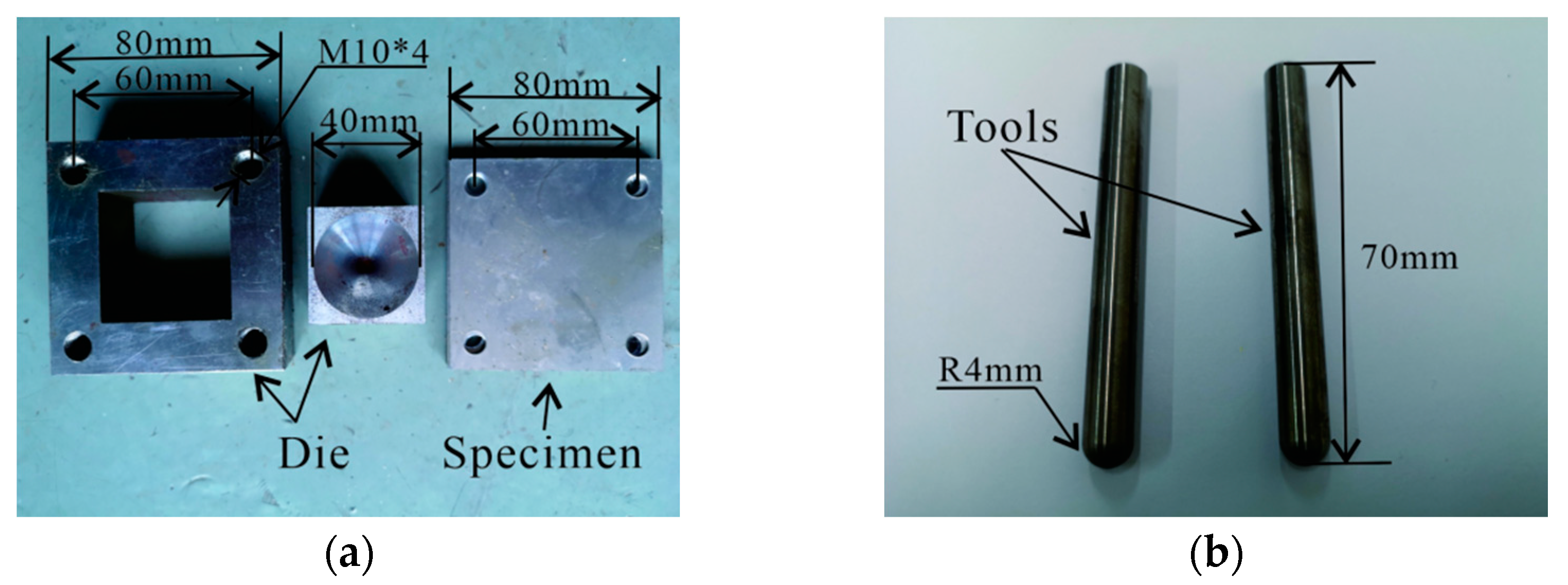
2.2. Preparation of Specimen and Tooling

Aluminum alloys are one of the most essential metals due to its good plasticity, high specific strength, excellent corrosion resistance, and low cost. The 7075 aluminum alloy with the highest strength has been widely applied to aerospace, automobile, ship, and die machining, mainly including girder, bulkhead, junction, and integral panels, which are the main load-carrying structure of planes. While it has a large application in industry, engineers face significant manufacturing problems of the low processing properties caused by the high mechanical strength and efficient cooperation of plastic forming and surface strengthening of the 7075 aluminum alloy. To investigate this further, a 2D ellipse ultrasonic vibration incremental forming test of the thin-walled panel of the 7075 aluminum alloy was designed in this paper. Thin-walled specimens of the 7075 aluminum alloy used for 2D ellipse ultrasonic vibration incremental forming tests to investigate the macroscopic mechanical properties and micro-structure evolution under different conditions of ultrasonic vibration are shown in Figure 1a. The specimens were machined with a wire-cut electrical discharge machine.
Unlike the traditional punching process, the single-point incremental forming process of curve surface sheet metal mainly relies on the layered forming path of the single-point tool instead of the conventional punching die. It is obvious that the single-point forming tool suffers more strike, friction, and heat than the incremental forming die, which plays a vital role in improving the quality and geometrical accuracy of the forming sheet by supporting and fastening it. Therefore, the single-point forming tools were made of high-temperature cemented carbide K25, which features a high-temperature abrasion resistance and long service life because of the high-temperature area of up to 200–800 °C that occurs at the ends of the tool. The tool works under conditions of intense friction and ultrasonic vibration. The single-point forming tool and die are shown in Figure 1a,b.

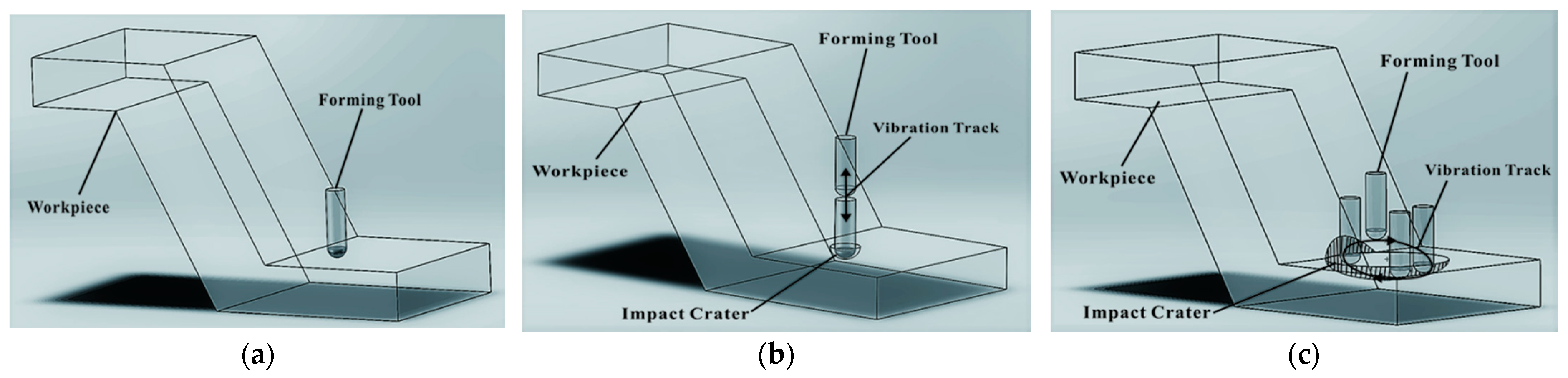
2.3. Method of Experiment

2.3.1. Design of Principle

As known, the most remarkable characteristic of the single-point incremental forming is that the metal sheet is extruded by the rolling tool point by point, according to the layered forming paths, which are a series of contour lines of the designed production. In Figure 2a, as the principle image of the single-point incremental forming shows, regional materials that contact the half-spherical head of the forming tool deforms permanently as the tool feeds horizontally or vertically. Compared to the traditional stamping process, this unique processing mode reduces the forming force and tremendously improves the manufacturing flexibility. At the same time, it causes the heterogeneous deformation and flow of materials. The severe problem of the thinning rate of the forming sheet hampers the application of the traditional incremental forming in manufacturing fields. Furthermore, it is difficult to utilize this technique to manufacture high-strength alloys. Rupture phenomena always occurs on metal sheets that are deformed beyond their forming limit. To conquer these challenging difficulties, ultrasonic energy is used in the softening of difficult-to-deform materials. In recent years, longitudinal ultrasonic vibration incremental forming has become a research hot spot due to some of its advantages. As Figure 2b shows, the sheet driven by a one-way ultrasonic device vertically vibrates relative to the forming tool. Then, the feeding and rolling tool impacts the sheet surface while it extrudes the deformed sheet. The half-spherical affected field caused by the impact actions marked as a shadow is present in Figure 2b. The longitudinal ultrasonic vibration incremental forming process features a special phenomenon of high frequency periodic contact–detach conditions of the sheet and the tool. The working mechanism causing a coupling action of ultrasonic effect, work hardening, heat softening, and stress superposition has been investigated. Moreover, the periodic extrusion ameliorates the intense friction condition between the sheet and the tool. This is beneficial to the improvement in the surface qualities of the forming sheet. However, the unidirectional ultrasonic vibration design only provides limited energy for material softening. The manufacture of complex thin-walled panels of high-strength alloys is still a challenging engineering problems. In addition, current technologies cannot fulfil the industry’s need for the surface strengthening and fatigue resistance of thin-walled parts. The bidirectional ultrasonic vibration device, which was successfully applied to other manufacturing fields, has never been used for incremental forming. In this work, a unique 2-dimension ellipse ultrasonic vibration method and device were designed. As Figure 2c shows, the forming sheet driven by the designed 2-dimension ellipse ultrasonic device vibrates in an ellipse path relative to the forming tool. Compared to the second process, it dramatically increases the contact areas between the sheet and the tool. This affected area, marked as an ellipsoid shadow in Figure 2c, is divided into two parts. One part is located in the processing region. Materials in this area deform and flow under the extrusion action and ultrasonic effect of the rolling and vibrating tool. A coupling action of the ultrasonic softening effect, ultrasonic hardening effect, thermal softening effect, work hardening, refined crystalline strengthening, and stress superposition affects the micro-structure evolution and the mechanical behaviors of metal materials. It was deduced that the reinforced softening effects dominated in this process, which tremendously improved the forming limit of difficult-to-deform materials such as the 7075 aluminum alloy. The other part of the affected area was located in the adjacent processed region on the side wall of the sheet. Materials restricted by the supporting mold in this area cannot flow. This process, similar to shot-peening, created a huge number of impact craters and a layer of strengthening coating with the residual compressive stress field. Obviously, hardening effects play a leading role in this area. In other words, the most outstanding innovation of this work is that the proposed 2-dimension ellipse ultrasonic vibration incremental forming process and the unique double-mechanism method of sectionalized cooperative control of forming deformation and mechanical performance including an internal softening mechanism, which promotes the deformation of materials and a surface strengthening mechanism that improves superficial mechanical properties of the sheet. Therefore, this new technique could meet the challenging demands on aircraft panels of complex shape and strengthening surface. Micro-hardness tests, scanning electron microscope (SEM) (TESCON Company, Brno, Czech Republic) tests of the micro-structure, and residual stress tests were performed to prove the above assumptions.

2.3.2. Design of Equipment

To accomplish the above goals, it was significant and necessary to design and manufacture the 2D ellipse ultrasonic vibration system. This vibration system was installed on the workbench of the numerical control milling machine, which turned out to be a type of specialized equipment for the 2D ellipse ultrasonic vibration incremental forming tests. As Figure 3a shows, the two ultrasonic vibration devices with the same frequency (20 KHz) and amplitude (10 μm) were fixed on the workbench. They both contained a supersonic generator, filter, phase shifter, energy converter, and amplitude transformer. The amplitude transformer of the named X-axis vibration device was connected to the left profile of the vibration platform. One of the Z-axis devices was joined with the bottom of the vibration platform. The exact frequency and the phase difference of a quarter of the two ultrasonic vibration systems driving the platform vibrated in a 2D ellipse path. The long-axis and the short-axis of the ellipse path were equal to the vibration amplitude of the two devices, respectively.
Three kinds of forming experiments—single-point incremental forming process, longitudinal ultrasonic vibration incremental forming process, and 2D ellipse ultrasonic vibration incremental forming process—were performed on the specialized ultrasonic equipment. The die installed above the vibration platform of the equipment was used to fix the part and assist in forming. The spherical tool with a rolling speed of 500 r/min adopted movements of horizontal feeding at a constant velocity of 500 mm/min and vertical feeding at a layered depth of 0.1 mm, once each time. The specialized ultrasonic equipment, conical specimens, and processing procedure are shown in Figure 3b–d.

3. Results and Discussion

3.1. Mechanical Property

After single-point incremental forming tests, longitudinal ultrasonic vibration incremental forming tests and 2D ellipse ultrasonic vibration incremental forming tests, five groups of the Vickers micro-hardness tests were performed on the HMAS automatic hardness testing and analysis system with a testing force of 1000 g and testing time of 20 s to research the effect of ultrasonic vibration on the mechanical property of the 7075 aluminum alloy. The hardness tests were independently conducted on the surface of the unprocessed 7075 aluminum alloy sheet, the single-point incremental forming part, the longitudinal ultrasonic vibration incremental forming part, and the 2D ellipse ultrasonic vibration incremental forming part and cross-section of the 2D ellipse ultrasonic vibration incremental forming part. As Figure 4a shows, five isometric testing points on the conical part were uniformly distributed along the depth direction. To confirm the accurate results of the hardness experiments, the specimen was measured repeatedly five times at each testing point. The average value of the five measurement values was the final hardness value of the testing point. Figure 4b shows the Vickers micro-hardness curves of five groups of testing points. It could be found that compared to the unprocessed sheet of the 7075 aluminum alloy, the surface micro-hardness of the SPIF part increased by 17.67%, the surface micro-hardness of the longitudinal ultrasonic vibration incremental forming part increased by 38.2%, and the surface micro-hardness of the 2D ellipse ultrasonic vibration incremental forming part increased by 50.12%. Particularly, the cross-sectional micro-hardness of the 2D ellipse ultrasonic vibration incremental forming part only increased by 6.87%. The experimental results imply that the proposed 2D ellipse ultrasonic vibration incremental forming process produces a more powerful surface strengthening effect on the surface of the 7075 aluminum alloy sheet than the other two techniques. It could be deduced that work hardening and ultrasonic hardening play a leading role in this region. In addition, the testing results also showed that the mechanical properties of the core materials of the sheet for 2D ellipse ultrasonic vibration incremental forming were similar to or even lower than that of raw materials of the 7075 aluminum alloy. As known, a coupling mechanism of ultrasonic softening, ultrasonic hardening, thermal softening, work hardening, refined crystal strengthening, and superposition stress occurs in the ultrasonic forming process. Obviously, it is easily inferred that the softening effects merely counteract the hardening effects inside the sheet for the 2D ellipse ultrasonic incremental forming. In brief, the hardness experimental results totally confirm the double-mechanism assumption.

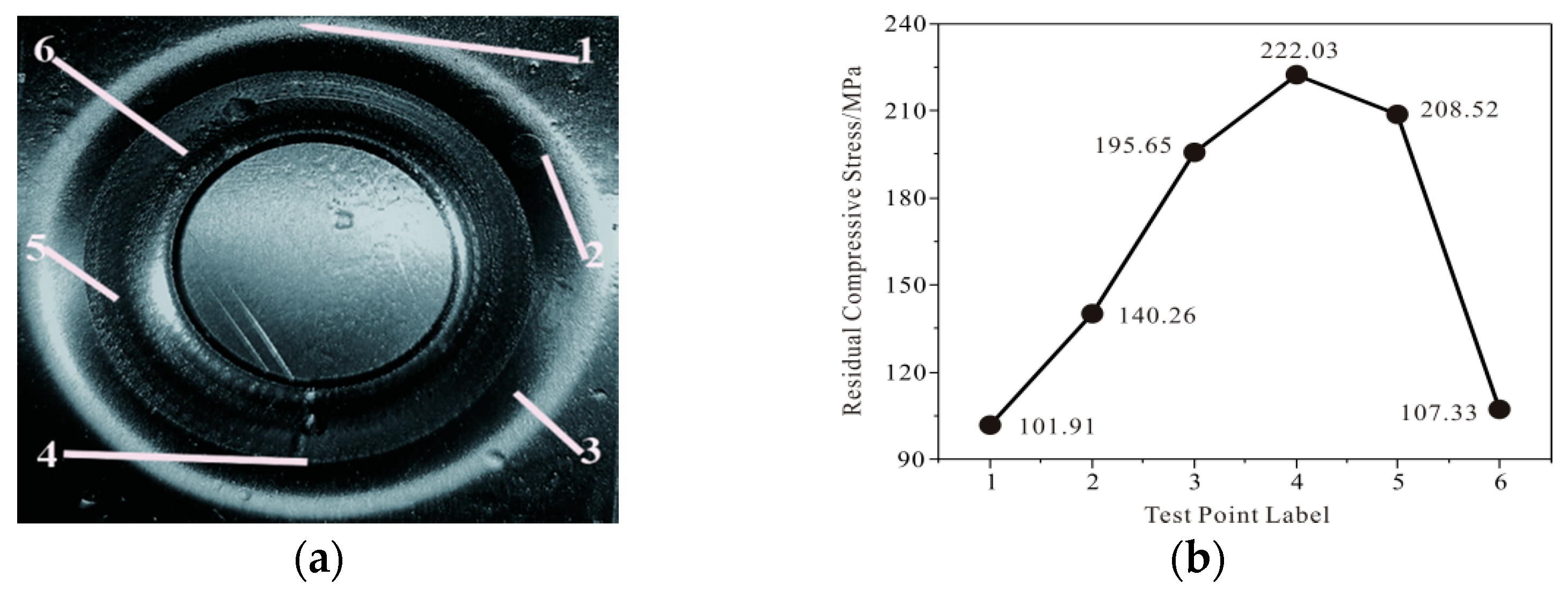
3.2. Residual Stress

To investigate the residual stress field of the 7075 aluminum alloy parts induced by 2D ellipse ultrasonic vibration incremental forming, residual stress tests were carried out on the i-XRD residual stress test and analysis system produced by the PROTO company in Canada (Aaugha). Testing standards of ASTM E915-2010 [26] and EN 15305-2008 [27] were conducted in residual stress tests. The testing conditions are listed as follows: tube voltage of 20 KV, tube current of 4 mA, radiation of CrKα, the wavelength of 2.291 m, diffraction crystal plane of (FCC, (311)), X-ray elastic constant of (1/2) S2 = 19.54 × 10⁻⁶ MPa−1, and S1 = −5.11 × 10⁻⁶ MPa−1.
According to the principle of equal angle in the circumferential direction and equal distance in the depth direction, six points distributed on a spiral line shown in Figure 5a were selected to test the residual stress. Figure 5b shows the residual stress values of the testing points on the conical part for the 2D ellipse ultrasonic vibration incremental forming. The negative stress values of the six sampled points indicate that the 2D ellipse ultrasonic vibration incremental forming could produce a residual compressive stress field on the surface of the conical part. The minimum absolute value of residual stress of −101.91 and −107.33 MPa occurred at the top and bottom of the conical part, respectively. The maximum absolute value of residual stress of −222.03 MPa appeared in the middle of the sidewall of the conical portion. Moreover, similar measuring results were probed at locations of No. 3 and No. 4. From this evidence, it was deduced that there was a significant gap between testing points at various depths, but fewer differences occurred in the circumferential direction. This was mainly due to the lack of enough support at the top and the bottom of the conical part. Elastic recovery and deformation led to a decrease in residual stress. Obviously, to obtain homogeneous residual compressive stress on the surface of the forming part and improve its fatigue resistance performance, it is necessary to facilitate its supporting conditions through optimized processing planning during the 2D ellipse ultrasonic vibration incremental forming procedure.

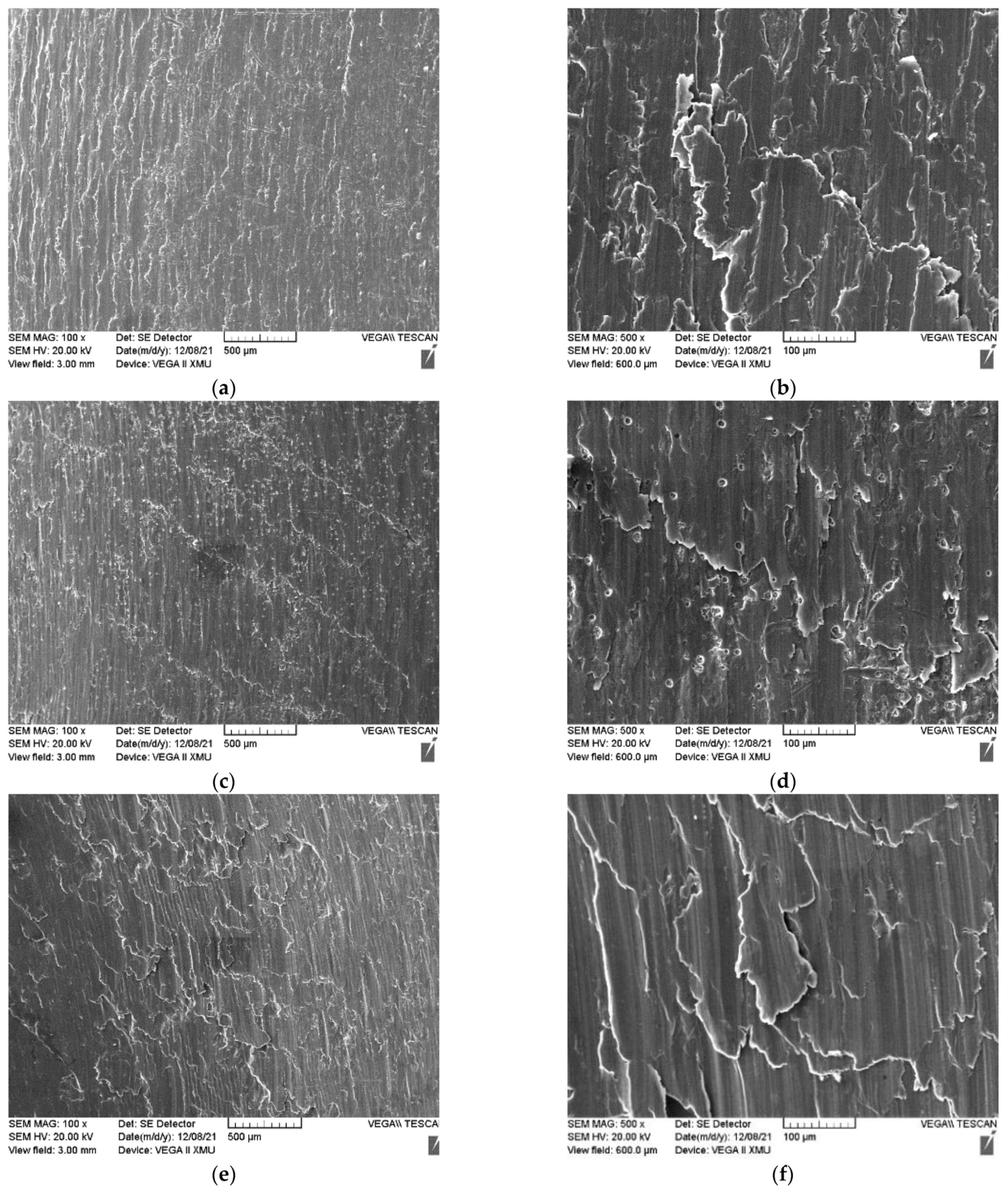
3.3. Micro-Structures and Fracture Features

Three metal sheets of 7075 aluminum alloy were processed separately with single-point incremental forming, longitudinal ultrasonic vibration incremental forming, and 2D ellipse ultrasonic vibration incremental forming until fracture occurred. Then, their machined surfaces and fracture morphology were observed on a scanning electron microscope. Some comparative analyses were performed to identify their surface morphology and fracture features and to study the effect of ultrasonic vibration on the mechanisms of deformation and fracture of the high strength aluminum alloy materials from a microscopic perspective.
In incremental forming, the metal sheet is deformed under an extruding force and frictional force is provided by the rolling single-point tool with feeding movement. When the metal sheet is in contact with the forming tool, it is inevitable that its surface will be scratched by the ultra-hard tool. Local material is deformed and departs from the sheet surface, then it becomes metal debris, which further aggravates its surface quality. Figure 6a shows that a mass of apparent and dense scratches and layered lacerations were created on the surface of the sheet. Some small flake debris almost peeling from the sheet surface were observed in Figure 6b. This was mainly due to the constant extrusion effect on its surface implemented by the tool, which produced severe deformation and strong friction during the traditional single-point incremental forming process. The longitudinal ultrasonic vibration incremental forming process could decrease the forming force and improve the contact condition between the sheet and the tool because the aided ultrasonic vibration device reduced their contact area and time. As Figure 6c shows, there were more light and superficial scratches and lacerations on the sheet surface than in Figure 6a. However, a large number of circular cavities with a diameter of about 10 μm was observed in Figure 6d. It is easy to deduce that a few micro-debris might get into the processing area when the tool is briefly apart from the sheet surface driven by the longitudinal ultrasonic vibration device, and then the one located at the central axis of the spherical-top tool becomes a piece of sharp and hard abrasive, which drills a circular cavity with the device falling and revolving in high-speed. This clearly explains the formation of these circular cavities with regular shapes and similar sizes. Moreover, the holes could undermine the surface integrity of the product. The 2D ellipse ultrasonic vibration incremental forming proposed in this paper adopted a kind of unique mode of ultrasonic vibration, which drives the forming tool to move in an ellipse path relative to the sheet. On one hand, this kind of high frequency and intermittent extruding action also reduce the forming force and improves friction condition. Figure 6e displays a few slight scratches on its surface. On the other hand, the tool vibrating in a 2D ellipse path fiercely impacted the sheet surface. Then, some big-flake lacerations were produced as well as the strengthening layer because of the compound vibration.
As known, fracture morphology is important and necessary for material analysis. It always clearly signifies how the micro-structure of the metal evolved and what kind of fracture characteristic it is. (1) As Figure 7a shows, the fracture surface of the specimen processed by the SPIF method was flat, with only a few dimples and some shallow pits were distributed on it. Figure 7b,c displays the back-scattered electron image (BEI) and the secondary electron image (SEI) of the sample surface topography in the same position. It is easy to see that the distribution of dimples and the location of strengthening phases and impurities in the 7075 aluminum alloy was highly identical. This was mainly due to the weakness of adhesion between the strengthening phases or impurities and the metal substrate. Then, some cavities were formed preferentially at the location of those secondary phases. The growing and aggregating adjacent cavities tended to become big dimples by annexing small dimples nearby. However, the 7075 aluminum alloy, which possesses high strength and poor plastic forming capacity at room temperature, only created tiny plastic deformation under loading. The cracks rapidly grew, causing flat dimples. (2) Figure 7d revealed distinct roughness of fracture surface of 45 degrees. At first, the nucleation, growth, and connection of a small number of tiny dimples occurred nearby the strengthening phases. These shear dimples that occurred in Figure 7e signifies an obvious directional consistency. By magnifying the object 2000 times, a considerable volume of extremely tiny dimples hiding in larger dimples could clearly be seen in Figure 7f. A few strengthening phase particles appeared in these larger dimples. It could be deduced that parts of the strengthening phases cracked under the huge shearing load. One part of these heterogeneous particles started to fall from the original position, but the other part of the strengthening phases still stayed in the original location. Due to the plastic deformation limit of the 7075 aluminum alloy, dimples stopped forming and growing. Then, a large number of tearing ridges appeared and extended in the ways of connecting contiguous dimples. Each two adjacent tearing ridges expanded to become a cleavage plane. There was no time for a mass of micro-dimples to grow, which were distributed on the nearby tearing ridge or on the planes. Therefore, the whole micro-topography of the fracture surface presented a beach-like appearance. The phenomenon of the coexisting tearing ridge and dimple indicates a typical complex pattern of quasi-cleavage fracture and ductile fracture. In contrast with the former SPIF sample, the micro-topography characteristic of the longitudinal ultrasonic vibration incremental forming sample showed that the plasticity and flexibility of the high-strength 7075 aluminum alloy showed a certain improvement with the action of one dimension ultrasonic vibration. However, a deficiency in the plastic deformation of this alloy material was induced by the improper design of the one-dimension ultrasonic device and lack of sufficient ultrasonic energy. (3) Unlike the longitudinal ultrasonic vibration incremental forming, the two-dimension ellipse ultrasonic vibration device derives a forming tool to strike the sheet surface at an inclining angle. At the same time, this double-vibration design increased the ultrasonic energy greatly to reinforce the sheet surface and soften its interior material. Figure 7g shows that the image of the fracture surface morphology of the 7075 alloy sheet processed by the 2D ellipse ultrasonic vibration incremental forming method confirms this assumption. As Figure 7g shows, it is easy to divide the whole fracture surface into two distinct areas according to its magnifying micro-morphology characteristic. The upper area with a thickness of about 200 μm nearby the machined surface showed fewer patterns and was smoother. The lower area, far from the machined surface, displayed abundant and density toughness fracture features. Figure 7h–j presents images of amplifying the marked area 1, area 2, and area 3 in Figure 7g 500 times. In Figure 7h, a mass of large and deep dimples was distributed uniformly in this area. It is reasonable to deduce that multiple coupling actions of ultrasonic softening, ultrasonic hardening, work hardening, stress superposition and heating softening were induced by the strong 2D ultrasonic vibration. Moreover, softening mechanisms played a dominant role in the forming process. Therefore, great dimples were generated and kept growing quickly along with the increase in the forming stress and the plastic deformation. While the softening alloy material was getting close to its plastic limit, the formed dimples and the forming ones began to tear. In particular, materials around those dimples deformed heavily before a bright tearing ridge appeared. Therefore, the petal-shaped micro-topography containing a mass of great dimples and micro ones, as shown in Figure 7h, proved the assumption of a material-softening-dominant mechanism in the 2D ellipse ultrasonic vibration incremental forming process. Comparing Figure 7h with Figure 7i, it is easy to see that more quasi-cleavage planes appeared in area 2, which was far away from the source of ultrasonic vibration due to the attenuation of the material-softening mechanism and a reduction in plastic deformation. A long-distance softening mechanism could probably be realized by the design of a new 3D ellipse ultrasonic vibration incremental forming method and the optimization of process parameters including the amplitude, power, and frequency of the ultrasonic vibration system. Figure 7j clearly displays the contrast of the fracture topography between the superficial strengthening layer and the internal softening-layer. The magnifying images of the marked areas 4 and 5 are shown in Figure 7k,l. A trans-granular crack with an angle of 45 degrees almost penetrated the whole strengthening layer. Nevertheless, there were a few short inter-granular cracks observed in the softening layer. Large crushed secondary-phase particles were left in the dimples. Part of those strengthening phases was crushed badly under the forming load and shearing force that formed during the fracture process. It proved that these dimples tended to nucleate first at the location of secondary phases, which were also the source of the short cracks. Furthermore, a considerable volume of micro-dimples of about 5 μm in diameter were observed surrounding the large ones. This indicates that the metal sheet fractured too early before those micro-dimples grew larger. Therefore, the softening-alloy deformed vastly, but still insufficiently. This phenomenon is consistent with the multiple coupling action of softening and hardening in the 2D ellipse ultrasonic vibration incremental forming process. On one hand, the softening effect generated many great dimples. On the other hand, the hardening mechanism restrained the size growth of the micro-dimples. At the same time, it was clearly stated that these great dimples were caused by a plastic slip of fibrous particles instead of detachment or the rupture of a single huge secondary phase. As Figure 7l shows, the delicate fiber-shape micro-structure was evenly distributed on the fracture surface of the hardening layer. The micro-hardness testing results prove that the surface hardness was improved significantly by the 2D ellipse ultrasonic vibration incremental forming process. This was closely related to the strengthening coating of the fibrous micro-structure caused by work-hardening and ultrasonic hardening. Probing the fracture surface carefully, some stretched dimples hiding between the fibers were observed. Aside from the secondary effects of the multiple softening, it was reasonable to conclude that the hardening mechanism plays an important role in the evolution of the micro-structure and properties of the surface layer.

4. Conclusions

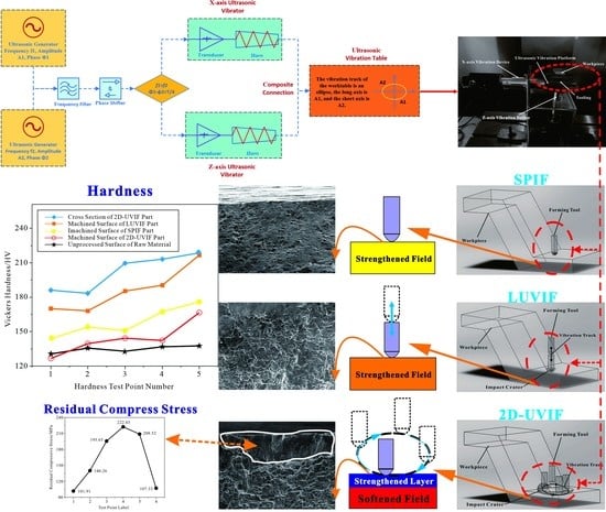
  • In this work, a type of 2-dimension ellipse ultrasonic vibration incremental forming process and its unique double-mechanism method of the sectionalized cooperative control of deformation formation and mechanical performance including the internal softening mechanism, which promotes the deformation of materials, and the surface strengthening mechanism, which improves the superficial mechanical properties of sheet, were designed. This innovative technique aims to meet the challenging industry demands on the manufacture of thin-walled aircraft panels of a high-strength aluminum alloy with a complex shape and surface strengthening coating.
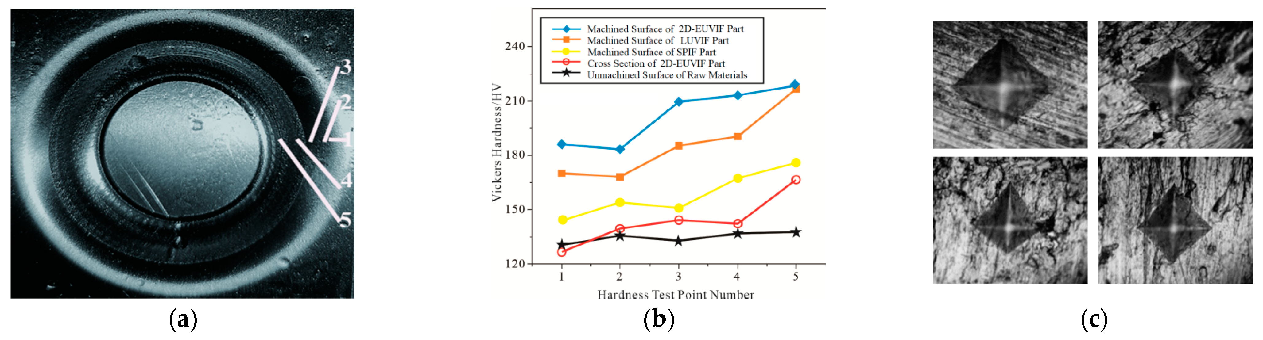
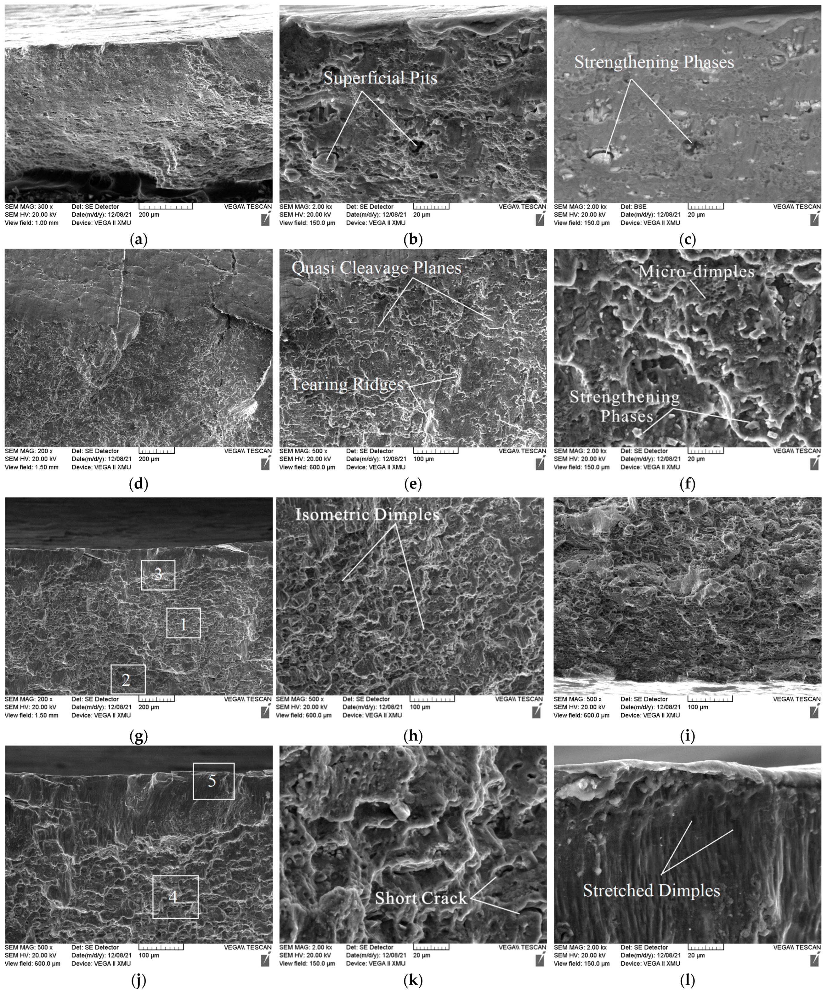
  • The experimental results showed that the mean value of the surface micro-hardness of the conical sheets processed by single-point incremental forming, longitudinal ultrasonic vibration incremental forming, and 2D ellipse ultrasonic vibration incremental forming were increased accordingly by 17.67%, 38.2%, and 50.13% compared to that of the raw materials of the 7075 aluminum ally. However, the mean value of the cross-sectional micro-hardness of the 2D ellipse ultrasonic vibration incremental forming sheet increased by only 6.87%. The experimental results demonstrated that the mechanical properties of the core materials of the part were nearly the same as or even lower than that of the raw materials. The SEM images of the fracture surface of the sheet for the novel forming technique showed distinct features of the surface strengthening coating with about a 200 μm fibrous-structure thickness and ductile fracture with a great number of dimples induced by softening effects. The testing results totally confirmed the double-mechanism assumption of internal softening and surface strengthening. In addition, a residual compressive stress field located on the surface of the sheet for the novel forming method could improve its fatigue resistance.
  • The SEM images of the fracture surface of the sheet for the novel technique showed that the ductile feature of the isometric dimples decreased along the depth and more quasi-cleavage planes appeared far from the source of ultrasonic vibration. Obviously, these phenomena were closely related to the affecting range of ultrasonic vibration. Although the double-mechanism method was proven to be feasible, the conditions for the motivating softening effects or hardening effects that play a leading role are still unknown. The precise quantification of ultrasonic softening, ultrasonic hardening, thermal softening, work hardening, refined crystalline strengthening, and stress superposition is challenging but vital for application of the 2D ellipse ultrasonic vibration incremental forming process and the double-mechanism method in industry.

Author Contributions

Conceptualization, Y.L.; Methodology, Y.L.; Investigation, Y.L.; Writing-Original Draft, Y.L.; Supervision, Y.L.; Funding acquisition, Y.L.; Data Curation, M.D.; Visualization, M.D.; Writing-Review & Editing, Y.L. and M.D.; Resources, X.P.; Project administration, C.Y. and J.S. All authors have read and agreed to the published version of the manuscript.

Funding

This research was funded by the National Natural Science Foundation of China (Grant Number 52005399), the Natural Science Basic Research Plan in Shaanxi Province of China (Grant Number 2016JQ5054), and the Special Scientific Research Program of the Shaanxi Provincial Department of Education (Grant Number 20JK0772).

Institutional Review Board Statement

Not applicable.

Informed Consent Statement

Not applicable.

Data Availability Statement

All the data are available within the manuscript.

Conflicts of Interest

The authors declare no conflict of interest.

References

  1. Liu, C.; Zhao, Z.; Zhang, X.; Wang, J. A progressive approach to predict shot peening process parameters for forming integral panel of Al7050-T7451. Chin. J. Aeronaut. 2021, 34, 617–627. [Google Scholar] [CrossRef]
  2. Wang, D.; Xu, F.; Yuan, L.; Zhang, D.; Liu, J.; Hu, Y.; Kang, H.; Ma, Q.; Tong, Y.; Han, W. Brief introduction and recent development on the manufacture of aluminium alloy integral panels in aerospace applications. Int. J. Mater. Struct. Integr. 2021, 14, 299–318. [Google Scholar] [CrossRef]
  3. Malhotra, R.; Xue, L.; Belytschko, T.; Cao, J. Mechanics of fracture in single point incremental forming. J. Mater. Process. Technol. 2012, 212, 1573–1590. [Google Scholar] [CrossRef]
  4. Aerens, R.; Eyckens, P.; Van Bael, A.; Duflou, J.R. Force prediction for single point incremental forming deduced from experimental and FEM observations. Int. J. Adv. Manuf. Technol. 2010, 46, 969–982. [Google Scholar] [CrossRef]
  5. Vanhove, H.; Mohammadi, A.; Guo, Y.S.; Duflou, J.R. High-Speed Single Point Incremental Forming of an Automotive Aluminium Alloy. Key Eng. Mater. 2014, 622–623, 433–439. [Google Scholar] [CrossRef]
  6. Bastos, R.N.P.; De Sousa, R.J.A.; Ferreira, J.A.F. Enhancing time efficiency on single point incremental forming processes. Int. J. Mater. Form. 2016, 9, 653–662. [Google Scholar] [CrossRef]
  7. Azevedo, N.G.; Farias, J.S.; Bastos, R.P.; Teixeira, P.; Davim, J.P.; de Sousa, R.J.A. Lubrication aspects during Single Point Incremental Forming for steel and aluminum materials. Int. J. Precis. Eng. Manuf. 2015, 16, 589–595. [Google Scholar] [CrossRef]
  8. Trzepieciński, T.; Kubit, A.; Dzierwa, A.; Krasowski, B.; Jurczak, W. Surface Finish Analysis in Single Point Incremental Sheet Forming of Rib-Stiffened 2024-T3 and 7075-T6 Alclad Aluminium Alloy Panels. Materials 2021, 14, 1640. [Google Scholar] [CrossRef]
  9. Bansal, A.; Lingam, R.; Yadav, S.K.; Reddy, N.V. Prediction of forming forces in single point incremental forming. J. Manuf. Process. 2017, 28, 486–493. [Google Scholar] [CrossRef]
  10. Zhang, H.; Lu, B.; Chen, J.; Feng, S.; Li, Z.; Long, H. Thickness control in a new flexible hybrid incremental sheet forming process. Proc. Inst. Mech. Eng. Part B J. Eng. Manuf. 2017, 231, 779–791. [Google Scholar] [CrossRef]
  11. Liu, S.; Shan, X.; Guo, K.; Yang, Y.; Xie, T. Experimental study on titanium wire drawing with ultrasonic vibration. Ultrasonics 2018, 83, 60–67. [Google Scholar] [CrossRef]
  12. Zhou, H.; Cui, H.; Qin, Q.H. Influence of ultrasonic vibration on the plasticity of metals during compression process. J. Mater. Process. Technol. 2018, 251, 146–159. [Google Scholar] [CrossRef]
  13. Tao, G.; Ma, C.; Bai, L.; Shen, X.; Zhang, J. Feed-direction ultrasonic vibration−assisted milling surface texture formation. Mater. Manuf. Process. 2017, 32, 193–198. [Google Scholar] [CrossRef]
  14. Sun, S.; Tang, J.; Shao, W.; Chen, C.; Liu, Y. Research on the matching relationship between ultrasonic-assisted grinding parameters and workpiece surface roughness. Int. J. Adv. Manuf. Technol. 2019, 102, 487–496. [Google Scholar] [CrossRef]
  15. Hu, J.; Shimizu, T.; Yang, M. Investigation on ultrasonic volume effects: Stress superposition, acoustic softening and dynamic impact. Ultrason. Sonochem. 2018, 48, 240–248. [Google Scholar] [CrossRef] [PubMed]
  16. Siddiq, A.; El Sayed, T. Ultrasonic-assisted manufacturing processes: Variational model and numerical simulations. Ultrasonics 2012, 52, 521–529. [Google Scholar] [CrossRef] [PubMed]
  17. Deshpande, A.; Hsu, K. Acoustic energy enabled dynamic recovery in aluminium and its effects on stress evolution and post-deformation microstructure. Mater. Sci. Eng. A 2018, 711, 62–68. [Google Scholar] [CrossRef]
  18. Hu, J.; Shimizu, T.; Yoshino, T.; Shiratori, T.; Yang, M. Ultrasonic dynamic impact effect on deformation of aluminum during micro-compression tests. J. Mater. Process. Technol. 2018, 258, 144–154. [Google Scholar] [CrossRef]
  19. Li, Y.; Chen, X.; Sun, J.; Li, J.; Zhao, G. Effects of ultrasonic vibration on deformation mechanism of incremental point-forming process. Procedia Eng. 2017, 207, 777–782. [Google Scholar] [CrossRef]
  20. Zhai, W.; Li, Y.; Cheng, Z.; Sun, L.; Li, F.; Li, J. Investigation on the forming force and surface quality during ultrasonic-assisted incremental sheet forming process. Int. J. Adv. Manuf. Technol. 2020, 106, 2703–2719. [Google Scholar] [CrossRef]
  21. Sakhtemanian, M.R.; Honarpisheh, M.; Amini, S. A novel material modeling technique in the single-point incremental forming assisted by the ultrasonic vibration of low carbon steel/commercially pure titanium bimetal sheet. Int. J. Adv. Manuf. Technol. 2019, 102, 473–486. [Google Scholar] [CrossRef]
  22. Sun, Y.; Lu, Z.; Li, C.; Wang, R.; Zhai, W. Study on the Springback Effect and Surface Property for Ultrasonic-Assisted Incremental Sheet Forming of Aluminum Alloy. Symmetry 2021, 13, 1217. [Google Scholar] [CrossRef]
  23. Li, Y.; Zhai, W.; Wang, Z.; Li, X.; Sun, L.; Li, J.; Zhao, G. Investigation on the material flow and deformation behavior during ultrasonic-assisted incremental forming of straight grooves. J. Mater. Res. Technol. 2020, 9, 433–454. [Google Scholar] [CrossRef]
  24. Amini, S.; Gollo, A.H.; Paktinat, H. An investigation of conventional and ultrasonic-assisted incremental forming of annealed AA1050 sheet. Int. J. Adv. Manuf. Technol. 2016, 90, 1569–1578. [Google Scholar] [CrossRef]
  25. Li, Y.; Cheng, Z.; Chen, X.; Long, Y.; Li, X.; Li, F.; Li, J.; Twiefel, J. Constitutive modeling and deformation analysis for the ultrasonic-assisted incremental forming process. Int. J. Adv. Manuf. Technol. 2019, 104, 2287–2299. [Google Scholar] [CrossRef]
  26. ASTM E915-2010; Standard Test Method for Verifying the Alignment of X-ray Diffraction Instrumentation for Residual Stress Measurement. ASTM International: West Conshohocken, PA, USA, 2010. Available online: https://www.mendeley.com/catalogue/0dc87e11-4cd6-33f1-b58d-498da3460460/ (accessed on 3 November 2022).
  27. EN 15305-2008; Non-Destructive Testing-Test Method for Residual Stress Analysis by X-ray Diffraction. Beuth GmbH: Berlin, Germany, 2009. Available online: https://www.antpedia.com/standard/pdf/H26/1702/BS%20EN%2015305-2008_1875.pdf (accessed on 3 November 2022).
Figure 1. Devices for incremental forming. (a) Specimen and die. (b) Forming tools.
Coatings 12 01914 g001
Figure 2. Ultrasonic vibration mode of progressive forming. (a) Without ultrasonic vibration; (b) vertical ultrasonic vibration; (c) 2D ultrasonic vibration.
Coatings 12 01914 g002
Figure 3. The 2D ultrasonic vibration incremental forming system. (a) Design of the 2D ultrasonic vibration system; (b) specialized equipment; (c) processing procedure; (d) processed specimens.
Coatings 12 01914 g003
Figure 4. Micro-hardness tests of samples for various forming techniques. (a) Hardness testing points; (b) hardness curves; (c) micro-hardness test images (from upper left to lower right: 7075 aluminum alloy raw material, incremental forming sample, vertical vibrating ultrasonic incremental forming sample, and elliptic vibrating ultrasonic incremental forming sample. Notes: 2D-EUVIF is the abbreviation for 2D ellipse ultrasonic vibration incremental forming; LUVIF is the abbreviation for longitudinal ultrasonic vibration incremental forming; SPIF is the abbreviation for single-point incremental forming). (Notes: The numbers 1–5 in Figure 4a represent accordingly five testing points located equidistantly on the inside wall of the conical part.)
Coatings 12 01914 g004
Figure 5. Residual compressive stress of the 2D-UVIF part. (a) Locations of residual stress testing points. (b) Residual compressive stress curve. 2D-EUVIF is the abbreviation for 2D ellipse ultrasonic vibration incremental forming. (Notes: The numbers 1–6 accordingly represent six testing points located on the inside wall of the conical part.).
Coatings 12 01914 g005
Figure 6. Surface morphology of specimens for SPIF, LUVIF and 2D-EUVIF. (a) 100×, SPIF; (b) 500×, SPIF; (c) 100×, LUVIF; (d) 500×, LUVIF; (e) 100×, 2D-EUVIF; (f) 500×, 2D-EUVIF; 2D-EUVIF is the abbreviation for 2D ellipse ultrasonic vibration incremental forming; LUVIF is the abbreviation for longitudinal ultrasonic vibration incremental forming; SPIF is the abbreviation for single-point incremental forming.
Coatings 12 01914 g006
Figure 7. The fracture morphology of the processed specimens for SPIF, LUVIF, and 2D-UVIF (SEM images of SE (secondary electrons) and BSE (backscatter electrons)). (a) SPIF, SE, 200×; (b) SPIF, SE, 2KX; (c) SPIF, BSE, 2KX; (d) LUVIF, SE, 200X; (e) LUVIF, SE, 500×; (f) LUVIF, SE, 2KX; (g) 2D-UVIF, SE, 200×; (h) 2D-UVIF, SE, 500X, District 1; (i) 2D-UVIF, SE, 500×, District 2; (j) 2D-UVIF, SE, 500×, District 3; (k) 2D-UVIF, SE, 2KX, District 4; (l) 2D-UVIF, SE, 2KX, District 5; 2D-EUVIF is the abbreviation for 2D ellipse ultrasonic vibration incremental forming; LUVIF is the abbreviation for longitudinal ultrasonic vibration incremental forming; SPIF is the abbreviation for single-point incremental forming. Notes: The numbers 1–5 with white boxes in (g,j) represent five testing areas and their magnified im-ages are accordingly showed in (hl).
Coatings 12 01914 g007
Table 1. Chemical composition of the 7075 aluminum alloy.
SiFeCuMnMgCrZnTiAl
≤0.4≤0.51.2–2.0≤0.32.1–2.90.18–0.285.1–6.1≤0.2Bal.
Publisher’s Note: MDPI stays neutral with regard to jurisdictional claims in published maps and institutional affiliations.

