
Improvement of 3D Printing Cement-Based Material Process: Parameter Experiment and Analysis
by
 , , ,
, , ,
Zihan Li
1,
Huanbao Liu
1,2,*,
Xiang Cheng
1,2,
Ping Nie
1,
Xianhai Yang
1,
Guangming Zheng
1,2,
Hongxing Su
1 and
Wenyu Jin
1 1
College of Mechanical Engineering, Shandong University of Technology, Zibo 255000, China
2
Shandong Provincial Key Laboratory of Precision Manufacturing and Non-Traditional Machining, Zibo 255000, China
*
Author to whom correspondence should be addressed.
Coatings 2022, 12(12), 1973; https://doi.org/10.3390/coatings12121973
Submission received: 16 November 2022
/
Revised: 9 December 2022
/
Accepted: 13 December 2022
/
Published: 16 December 2022
(This article belongs to the Special Issue Current Research in Cement and Building Materials)
Abstract
:Three-dimensional printing concrete is a digital and automating construction technology, which is expected to solve a series of problems existing in the traditional construction industry, such as low automation, high labor intensity, low efficiency and high risk. However, there are still many technical and operational challenges. The purpose of this paper is to provide insights into the effects of process parameters on the geometry and stability of the printed layer. Firstly, a theoretical model is established to analyze the structure of the printed layer under different nozzle speeds, material flow rates and nozzle offset. Secondly, a slump test is carried out to select the optimal ratio suitable for 3D cement printers, and the specimen is printed under various conditions. Finally, based on the obtained parameters, multiple nozzles are used for printing, and a pressure value suitable for each nozzle in the nonlinear path is calculated. The experimental results show that theoretical model can sufficiently verify printing structure in different parameter intervals, and the process parameters (nozzle speed, material flow rate and nozzle offset) can be changed to achieve the best effect of cement-based material forming structure.
1. Introduction
The construction industry accounts for about 10% of total world output, but productivity in construction has barely increased since 1945 [1,2,3]. Compared with other industrial sectors (such as manufacturing, retail and agriculture), the productivity of the construction industry is extremely low: there are problems such as low technological content of production mode and lagging technological innovation. Meanwhile, problems such as the aging population and rising labor costs are gradually aggravated. Therefore, many researchers are urgently exploring solutions to change this situation.
With advent of Industry 4.0 [4], improving the degree of automation in the manufacturing stage of the construction process is expected to solve the problem of low productivity [5]. In this context of rapid development, construction 3D printing is an effective way to improve the current situation of the construction industry. Because the construction process has better degrees of freedom, lower labor costs and faster productivity, it has received wide attention [6,7,8,9,10]. At present, construction 3D printing has contour crafting [11,12], D-shape [13], concrete printing [14] and construction methods that are applicable to the field of architecture, and have also been successfully applied to artificial bridge construction, military shelters, rapid disaster relief shelters [15,16,17,18] and complex structures (an ultra-high-performance structure with complex geometric shapes designed by Gosselin et al. [19]). Different mechanical mechanisms and process parameters have certain influence on the shape, stability, material accumulation and fracture of the printed parts, that is, there are different forming effects, the geometric shape and local stability of the extrusion layer are key factors affecting the final deforming effect.
Many researchers have studied the influence of printing parameters on forming mechanism and obtained the corresponding optimal process parameters. Farahbakhsh, M et al. [20], by manipulating process parameters, the layer geometry was changed to simulate densification, and friction between successive layers was enhanced by periodically increasing the printed area or enhancing compaction during printing (Figure 1a,b). Carneau, P et al. [21] provide insights on the effect of printing parameters on the geometry and local stability of the extruded layer. The upper and lower limit requirements for controlling lamination are discussed from the influence of geometric and motion parameters, as well as from the study of the properties of fresh materials. (Figure 1c). Huang, X et al. [22] introduced the influence of printing parameters on molding quality and interlayer bond strength through single-factor experiment, and obtained corresponding printing parameters (Figure 1d). Chen, Y et al. [23] studied the influence of time interval and nozzle distance on the interlayer bond strength, and the results showed that extending the time interval could reduce bond strength, while only increasing the nozzle distance had limited influence on the bond strength (Figure 1e). Elistratkin, M et al. [24] studied the combined influence of factors such as layer thickness, nozzle speed and screw rotation speed on the extrusion and printing track parameters of building materials, and established the relationship between the above factors to improve the stability of the printing process and the final structural quality (Figure 1f). Based on the above discussion, the process parameters are the key technical indexes for building structure printing, which not only affect the interlayer bonding effect, but also have a certain impact on the appearance of the printed product. Therefore, it is necessary to carry out the research on the matching of the printing process parameters.
In this paper, the influence of process parameters on material fluidity and molding effect was studied by single-factor experiment, taking tailing sand content, resting time, nozzle speed, pressure and nozzle offset as influencing factors, and slump, embryo strength, layer height and layer width as combining indicators. The self-developed 3D concrete printing equipment was utilized to analyze the matching relationship of print parameter, which can be adjusted to optimize printing parameter combination was obtained and provided reference for related research.
2. Materials and Methods
2.1. Materials
In order to determine the optimum sand content, a mixing ratio test was designed P.O 42.5 ordinary Portland cement was selected as the main cementitious, and the first grade fly ash, S95 grade slag powder and SF96 grade silicon powder were used as admixture to improve the micro pore structure, bonding performance, cement-based strength and pumping performance of mortar [25]. In addition to the above cementing materials, the chemical admixture used hydroxypropyl methyl cellulose ether and sodium gluconate retarder, which can greatly improve the plasticity and water retention of mortar and prevent drying and cracking. Tailing sand was selected for fine aggregate, and its physical properties were shown in Table 1. In order to ensure accuracy of water–binder ratio, tailing sand should be dried and sealed before use to ensure that the moisture content is 0. The water used for the experiment was tap water or medium water (medium water generally refers to reclaimed water, waste water or rainwater after proper treatment, to reach a certain quality index, can be used for beneficial water), and the printing experiment were carried out at room temperature. The process parameters were shown in Table 2.
The mixing process is as follows: Firstly, weigh out cement, admixtures, sand and admixtures. Secondly, first the cement and admixture mix and stir evenly, then pour the sand into the mix evenly, and then pour the admixture into the mixture, stir for 2–3 min after all mixing. Finally, gradually add water and stir.
2.2. Methods
2.2.1. 3D Cement Printing Equipment
A self-developed four-axis motion 3D cement printer was used in the experiment (Figure 2a,b). The X-axis, Y-axis and Z-axis motion mechanism was composed of linear modules. Stepping motors were used to control A axis rotation. Numerical control technology was used to control the stroke accurately. The printing system of the equipment was divided into two parts: one is the extrusion device, including air source (Figure 2c), ink cartridge (Figure 2d) and nozzle (Figure 2e). The other part is the Mach3 control system that controls the operation of equipment (Figure 2f). The specification of the 3D printing system was show in Table 3.
2.2.2. Theory
Figure 3 summarizes the influence of cement-based material flow rate and nozzle speed on printing molding. The cement-based material can be squeezed through pressure control system, and the nozzle speed was controlled by stepper motor. With intermediate cement-based material flow-rate and nozzle speed, the width of the print layer will be similar to the nozzle diameter. In this case, the printing process can obtain more ideal specimen (Figure 3a). With a high flow-rate of cement-based material or low nozzle speed, the width of the print layer was often larger than the nozzle diameter (Figure 3b). A wider path will strengthen the bond between the layers and consequently achieve better mechanical properties, and on the other hand, the printing process can easily lead to material accumulation in narrow, non-linear paths. With a low flow-rate or high speed, the width of the print layer will be similar to or smaller than the nozzle diameter (Figure 3c). However, when the flow-rate was reduced (pressure value was less than 0.045 MPa), the cement-based material creates friction with the bottom surface, causing a dragging phenomenon and subsequent fracture (Figure 3d). The relationship between nozzle velocity and X, Y axis velocity is:
where F is the theoretical speed of nozzle, in mm/s. S is the theoretical displacement of nozzle, in mm. Vx is the actual speed in the X-axis direction, in mm/s. Lx is the actual displacement in the X-axis direction, in mm. Vy is the actual speed in the Y-axis direction, in mm/s and Ly is the actual displacement in the Y-axis direction in mm.
The material extrusion speed V1 is:
where t is the printing time, in s. b is the height of material falling in the ink cartridge during the printing time, in mm. r is the radius of the ink cartridge, in mm and A is the volume of material extruded during the printing time in mm3.
Figure 4 summarizes the influence of nozzle height on printing molding under optimal material flow-rate and nozzle speed. If the nozzle offset (H) was much larger than the nozzle diameter (d), the material gradually tilts forward, resulting in a layer height consistent with the nozzle offset, and the cross-section is trapezoidal (Figure 4a). In this case, the inter-layer contact area was smaller, and the inter-layer bond strength was weaker [21]. If H was equal to d, the surface will be slightly flattened by the nozzle, and a large inter-layer contact area can be obtained without destroying the shape (Figure 4b). If H was much smaller than d, the nozzle will push the cement-based material to both sides, forming thin layer (Figure 4c). In this case, there may be some cracks and other defects in the spilled concrete on both sides. The relationship between nozzle offset and specimen width as
where h is layer height, in mm. H is the nozzle offset and w is layer width in mm. When the volume of extruded material was constant, the layer height was inversely proportional to the layer width.
2.2.3. Experimental Procedure
By controlling the content of tailing sand, the cement-based materials have well fluidity, extrudability and constructability. The tailing sand content was set to 0%–50% when the other ratios were unchanged (gradient value of 10%), as show in Table 2. The mixed cement-based material was loaded into a 100 × 100 mm cylinder (Figure 5a) and then tamped with a tamper stick. The cylinder was removed, and the specimen was gradually pressurized until the specimen severely deformed (Figure 5b). The pressure was then converted to strength (Pressure divided by contact area, F = mg, P = F/S). After the optimal content of tailing sand was selected, the slump and strength were tested after 0, 5, 10, 15 and 20 min, respectively, to select the optimal printing time.
The theoretical model was verified under the support of optimal mix ratio. Experiments were designed to analyze the printing effect of cement-based materials under different parameters. Firstly, the influence of nozzle speed on molding effect was analyzed under the same pressure. The pressure was set to 0.045 MPa, and the nozzle speed was 1.667–13.333 mm/s (gradient value of 1.667 mm/s), as shown in Table 4. Secondly, the influence of pressure on the molding effect was analyzed at the same nozzle speed. The nozzle speed was set to 8.333 mm/s, and the pressure was set to 0.045–0.144 MPa (gradient value of 0.009 MPa), as shown in Table 5. Finally, the influence of different nozzle height on the molding effect was analyzed. The nozzle speed was set to 8.333 mm/s, the pressure was set to 0.117 MPa, the nozzle diameter was set to 10 mm and the nozzle height was set to 3, 5, 7.5, 10, 12 and 14 mm, as show in Table 6.
3. Analysis and Discussion
3.1. Slump Analysis
Cement-based materials were usually extruded by nozzles, and fluidity was a key parameter to evaluate the extrudability of materials. Therefore, the good fluidity in the printing process can ensure that cement-based material was smoothly extruded continuously from the nozzle without break, and was easy to deposit and molding. Fluidity was usually expressed in terms of slump: the test process of slump and strength is shown in Figure 6. Slump refers to the height of automatic deposition of cement-based material (Figure 6a), and strength is converted by applied pressure (Figure 6b). The variation of strength and slump with tailing sand content was shown in Figure 7a. The slump of specimens decreased with the increase in tailing sand content, which indicated that constructability of cement-based materials can be effectively improved while the fluidity is reduced. At the same time, it can be seen from the figure that the strength increases almost linearly with the increase in tailing sand content. Combined with strength and slump analysis, the best printing results were obtained when the tailing sand content was 40%. The changes in slump and strength with time are shown in Figure 7b. With the increase in time, the higher strength of material, the better constructability of material. However, with the increase in time, the slump gradually decreased. When the time was longer than 15 min, the material was almost no slump, which will cause pipe blockage and was not conducive to printing. Therefore, 10 min after the stirring was the optimal printing time.
3.2. Influence of Nozzle Speed and Pressure on Molding Effect
The extrudability of cement-based materials plays an important role in the experimental process, the pressure extrusion system is used to realize the on-demand extrusion of cement-based materials. Under high pressure conditions, the ink cartridges can burst due to excessive internal pressure and there are certain risks, cement-based materials were difficult to control, and material was difficult to extrude under low pressure. Therefore, in order to make the cement-based materials’ extrusion stable and controllable, the pressure was set to 0.045 MPa. At different nozzle speeds, the specimen morphology has different widths and heights. The width and height of the print layer variation with the nozzle speed are shown in Figure 8a. With the increase in nozzle speed, the width and height showed a downward trend.
In order to study the Influence of extrusion pressure on molding effect of cement-based materials and the optimal ratio of nozzle speed and extrusion speed, the nozzle speed was set to 8.333 mm/s (F500) according to the result in Figure 8a. Specimen had different morphology under different pressures. The variation of layer width and layer height with pressure are shown in Figure 8b. With the increase in pressure, the layer width and height showed an upward trend.
The printing effect of cement-based materials under different parameters is shown in Figure 9. When the nozzle speed was less than 3.333 mm/s (F200) and the pressure value was greater than 0.144 MPa, materials accumulation phenomenon will occur (Figure 9a). The surface of the specimen printed at low speed and high pressure was uneven, and materials accumulation can be obviously seen on the printing path (Figure 9d). However, an increase in layer width leads to increase in the contact area between layers, so the constructability was particularly outstanding in this case. On the contrary, when the nozzle speed was greater than 8.333 mm/s (F500) and the pressure value was less than 0.081 MPa, the shape of the printing specimen was not sufficient to support the printing of the next layer (Figure 9c). The specimens printed at high speed and low pressure have poor construction performance and were prone to collapse during printing (Figure 9f). When the nozzle speed was 8.333 mm/s and the pressure value was 0.117 MPa, the surface of the printing specimen was smooth and flat, and there was no material accumulation. At the same time, specimens has good constructability and ideal molding effect (Figure 9b,e).
3.3. Influence of Nozzle Offset on Molding Effect
Based on Section 3.2, the nozzle speed was set to 8.333 mm/s, the pressure was set to 0.117 MPa, and the nozzle diameter was set to 10 mm. Different nozzle offset lead to different deposition shapes. The changes in the layer width and layer height with the nozzle offset are shown in Figure 10. With the increase in the nozzle offset, the layer height showed an upward trend. When the nozzle offset was greater than or equal to the nozzle diameter, the layer height was consistent with the nozzle offset. According to Equation (8), the layer height was inversely proportional to the layer width, so the layer width showed downward trend.
The molding effect is shown in Figure 11. When the nozzle offset was less than 7.5 mm, compression condition of specimen was extremely serious, so the layer width was large (Figure 11a). When the nozzle offset was low for printing, the layer contact area was increased, and the constructability was improved. However, due to the severe extrusion of the printing layer, the materials will overflow on both sides of the printing path (Figure 11d). On the contrary, when the nozzle offset was greater than 10 mm, the layer height was larger and the layer width was smaller, which was not conducive to the support function of the lower layer to the upper layer, and higher the nozzle offset leads to inaccurate deposition, therefore, the constructability was poor (Figure 11c,f). In relative terms, the nozzle offset was set to be slightly smaller than the nozzle diameter. On the premise that the printing layer was not severely compressed, ensures good constructability, and at the same time, there was no material spillage during the printing process (Figure 11b,e).
3.4. Effect of Different Pressure on Multi-Nozzle Printing Molding
The nozzle device of the printer used in this paper can switch between single-nozzle extrusion and multi-nozzle extrusion by Mach3 control board. When multi-nozzle printing was carried out, different nozzles should be set different pressure values on the nonlinear path to ensure that there was no materials accumulation. Based on the results of Section 3.2 and Section 3.3, the nozzle speed of 8.333 mm/s, the pressure of 0.117 MPa, and the nozzle height of 7.5 mm were set as the basic parameters.
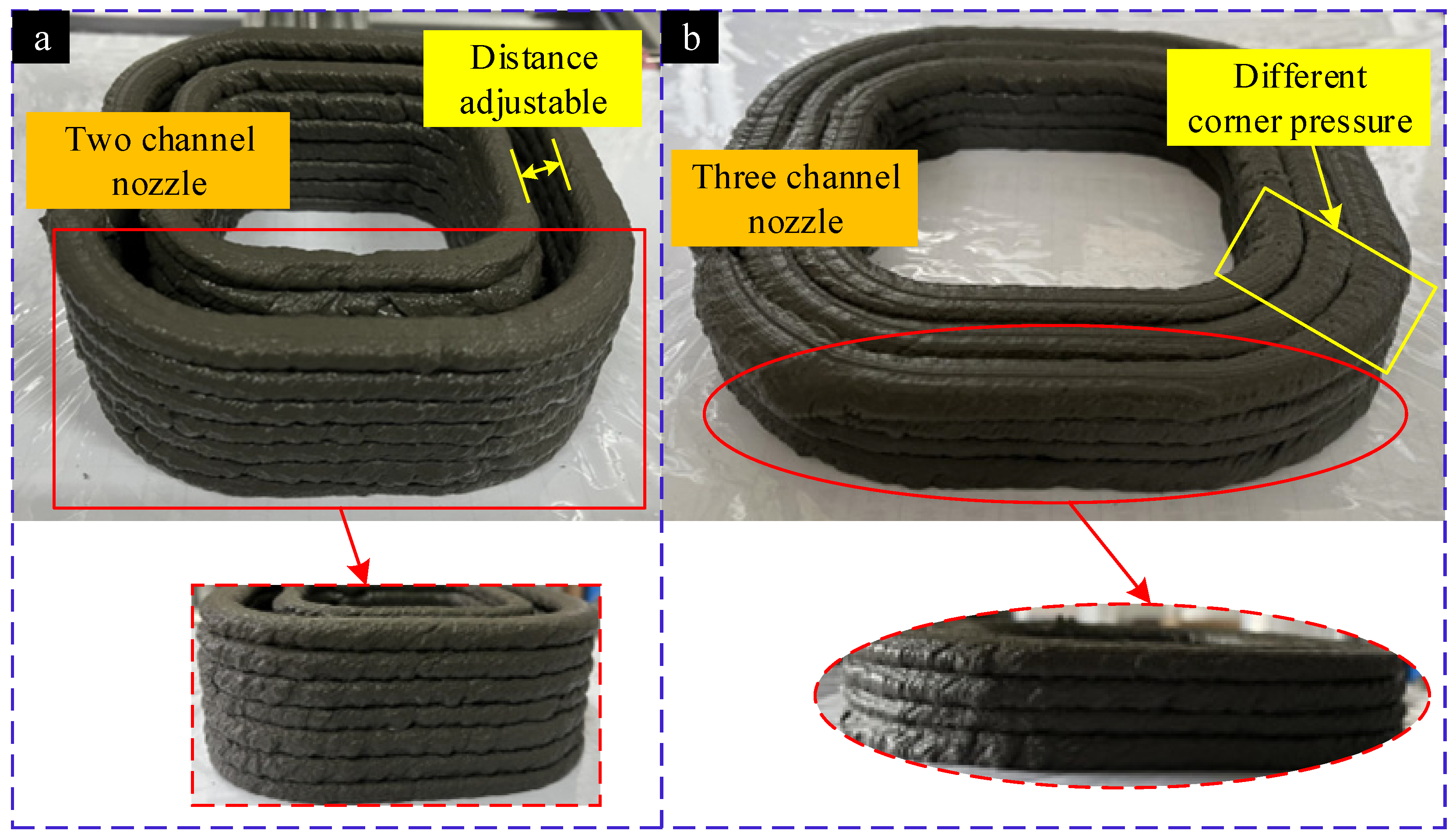
The molding effect of multi-nozzle printing as shown in Figure 12. When printing with double nozzles, the nozzle spacing can be adjusted, and the extrusion speed of each nozzle can be controlled by pressure, so as to meet the printing requirements of complex components. As shown in Figure 12a, the pressure value of inner ring was 0.099 MPa, and the pressure value of outer ring was 0.117 MPa. Therefore, the forming effect of the inner and outer rings was inconsistent. When the three nozzles are printed without spacing, the pressure value in the linear path was unified to 0.117 MPa. However, in the non-linear path, because the paths of the three nozzles are different, the pressure value of the nozzles should be adjusted to achieve the effect of no materials accumulation (Figure 12b). The relationship between material extrusion speed and arc length as
where l is the arc length, in mm. layer height and layer width were fixed values, the volume of material required to calculate the nonlinear path, and the printing time was the same. Therefore, extrusion speed of different paths was obtained, and pressure value of each nozzle was determined according to the extrusion speed.
4. Conclusions
The 3D printing concrete process opens up a novel construction method, which will improve the complexity, diversity and geometric accuracy of products, and bring higher production efficiency to the construction industry. This paper aimed to investigate the influence of different printing parameters on the material printing molding through theoretical analysis and experimental methods. The conclusions are as follows:
- (1)
- The success of the printed structure depends on the suitability of the properties of the cement-based material. Through strength and slump experiments, the optimal mix ratio suitable for 3D building printer was obtained, which can provide technical support for subsequent experiments.
- (2)
- According to the influencing factors such as nozzle speed, material flow rate and nozzle offset, the theoretical models under different process parameters were analyzed, which can provide theoretical support for the subsequent parameter experiments.
- (3)
- The experimental results show that the theoretical model can fully verify the print structure in different parameter intervals, the layer width and layer height can be controlled by changing the related parameters, which can effectively control the nozzle speed, material flow and nozzle offset to achieve the best effect of cement-based material forming structure.
Author Contributions
Z.L.: Data curation, Writing—Original draft preparation. H.L.: Conceptualization, Methodology, Writing—Reviewing and Editing. X.C.: Visualization, Software. P.N.: Writing—Reviewing and Editing. X.Y.: Investigation. G.Z.: Validation, Writing—Reviewing and Editing. H.S.: Formal analysis. W.J.: Data curation. All authors have read and agreed to the published version of the manuscript.
Funding
This research was funded by the Natural Foundation of Shandong Province (ZR2020QE179), National key research and development Program (2018YFB2001402-02) and the National Natural Science Foundation of China (No. 51505264).
Institutional Review Board Statement
Not applicable.
Informed Consent Statement
Not applicable.
Data Availability Statement
Not applicable.
Acknowledgments
The research undertaken was made possible by the equal scientific involvement of all the authors concerned.
Conflicts of Interest
The authors declare no conflict of interest.
References
- Hossain, A.; Zhumabekova, A.; Paul, S.; Kim, J. A Review of 3D Printing in Construction and its Impact on the Labor Market. Sustainability 2020, 12, 8492. [Google Scholar] [CrossRef]
- Crosthwaite, D. The global construction market: A cross-sectional analysis. Constr. Manag. Econ. 2000, 18, 619–627. [Google Scholar] [CrossRef]
- Horta, I.; Camanho, A.; Johnes, J.; Johnes, G. Performance trends in the construction industry worldwide: An overview of the turn of the century. J. Prod. Anal. 2013, 39, 89–99. [Google Scholar] [CrossRef]
- Hofmann, E.; Rüsch, M. Industry 4.0 and the current status as well as future prospects on logistics. Comput. Ind. 2017, 89, 23–34. [Google Scholar] [CrossRef]
- Cai, S.; Ma, Z.; Skibniewski, M.J.; Bao, S. Construction automation and robotics for high-rise buildings over the past decades: A comprehensive review. Adv. Eng. Inform. 2019, 42, 100989. [Google Scholar] [CrossRef]
- Bock, T. The future of construction automation: Technological disruption and the upcoming ubiquity of robotics. Autom. Constr. 2015, 59, 113–121. [Google Scholar] [CrossRef]
- Rayna, T.; Striukova, L. From rapid prototyping to home fabrication: How 3D printing is changing business model innovation. Technol. Forecast. Soc. Chang. 2016, 102, 214–224. [Google Scholar] [CrossRef] [Green Version]
- Jayathilakage, R.; Rajeev, P.; Sanjayan, J. Yield stress criteria to assess the buildability of 3D concrete printing. Constr. Build. Mater. 2020, 240, 117989. [Google Scholar] [CrossRef]
- Adaloudis, M.; Roca, J.B. Sustainability tradeoffs in the adoption of 3D Concrete Printing in the construction industry. J. Clean. Prod. 2021, 307, 127201. [Google Scholar] [CrossRef]
- Xiao, J.; Ji, G.; Zhang, Y.; Ma, G.; Mechtcherine, V.; Pan, J.; Wang, L.; Ding, T.; Duan, Z.; Du, S. Large-scale 3D printing concrete technology: Current status and future opportunities. Cem. Concr. Compos. 2021, 122, 104115. [Google Scholar] [CrossRef]
- Zhang, J.; Khoshnevis, B. Optimal machine operation planning for construction by Contour Crafting. Autom. Constr. 2013, 29, 50–67. [Google Scholar] [CrossRef]
- Khoshnevis, B. Automated construction by contour crafting—Related robotics and information technologies. Autom. Constr. 2004, 13, 5–19. [Google Scholar] [CrossRef]
- Cesaretti, G.; Dini, E.; De Kestelier, X.; Colla, V.; Pambaguian, L. Building components for an outpost on the Lunar soil by means of a novel 3D printing technology. Acta Astronaut. 2014, 93, 430–450. [Google Scholar] [CrossRef]
- Lim, S.; Buswell, R.; Le, T.; Austin, S.; Gibb, A.; Thorpe, T. Developments in construction-scale additive manufacturing processes. Autom. Constr. 2012, 21, 262–268. [Google Scholar] [CrossRef] [Green Version]
- Delgado, J.M.D.; Oyedele, L.; Ajayi, A.; Akanbi, L.; Akinade, O.; Bilal, M.; Owolabi, H. Robotics and automated systems in construction: Understanding industry-specific challenges for adoption. J. Build. Eng. 2019, 26, 100868. [Google Scholar] [CrossRef]
- Wu, P.; Wang, J.; Wang, X. A critical review of the use of 3-D printing in the construction industry. Autom. Constr. 2016, 68, 21–31. [Google Scholar] [CrossRef] [Green Version]
- Zhang, J.; Wang, J.; Dong, S.; Yu, X.; Han, B. A review of the current progress and application of 3D printed concrete. Compos. Part A Appl. Sci. Manuf. 2019, 125, 105533. [Google Scholar] [CrossRef]
- Xu, J.; Ding, L.; Love, P.E. Digital reproduction of historical building ornamental components: From 3D scanning to 3D printing. Autom. Constr. 2017, 76, 85–96. [Google Scholar] [CrossRef]
- Gosselin, C.; Duballet, R.; Roux, P.; Gaudillière, N.; Dirrenberger, J.; Morel, P. Large-scale 3D printing of ultra-high performance concrete—A new processing route for architects and builders. Mater. Des. 2016, 100, 102–109. [Google Scholar] [CrossRef] [Green Version]
- Farahbakhsh, M.; Rybkowski, Z.K.; Zakira, U.; Kalantar, N.; Onifade, I. Impact of robotic 3D printing process parameters on interlayer bond strength. Autom. Constr. 2022, 142, 104478. [Google Scholar] [CrossRef]
- Carneau, P.; Mesnil, R.; Baverel, O.; Roussel, N. Layer pressing in concrete extrusion-based 3D-printing: Experiments and analysis. Cem. Concr. Res. 2022, 155, 106741. [Google Scholar] [CrossRef]
- Huang, X.; Yang, W.; Song, F.; Zou, J. Study on the mechanical properties of 3D printing concrete layers and the mechanism of influence of printing parameters. Constr. Build. Mater. 2022, 335, 127496. [Google Scholar] [CrossRef]
- Chen, Y.; Jansen, K.; Zhang, H.; Rodriguez, C.R.; Gan, Y.; Çopuroğlu, O.; Schlangen, E. Effect of printing parameters on interlayer bond strength of 3D printed limestone-calcined clay-based cementitious materials: An experimental and numerical study. Constr. Build. Mater. 2020, 262, 120094. [Google Scholar] [CrossRef]
- Elistratkin, M.; Alfimova, N.; Podgornyi, D.; Olisov, A.; Promakhov, V.; Kozhukhova, N. Influence of Equipment Operation Parameters on the Characteristics of a Track Produced with Construction 3D Printing. Buildings 2022, 12, 593. [Google Scholar] [CrossRef]
- Jayswal, S.D.; Mungule, M. Performance assessment of Alccofine with silica fume, fly ash and slag for development of high strength mortar. Front. Struct. Civ. Eng. 2022, 16, 576–588. [Google Scholar] [CrossRef]
Figure 1.
Effect of different printing parameters. (a) Increased surface contact between successive layers [20], (b) Altering the geometry [20], (c) Over pressing of the sublayers [21], (d) Influence of printing speed on concrete size [22], (e) Increasing the nozzle standoff distance could lead to the inaccurate layer deposition [23], (f) Track printing process [24].
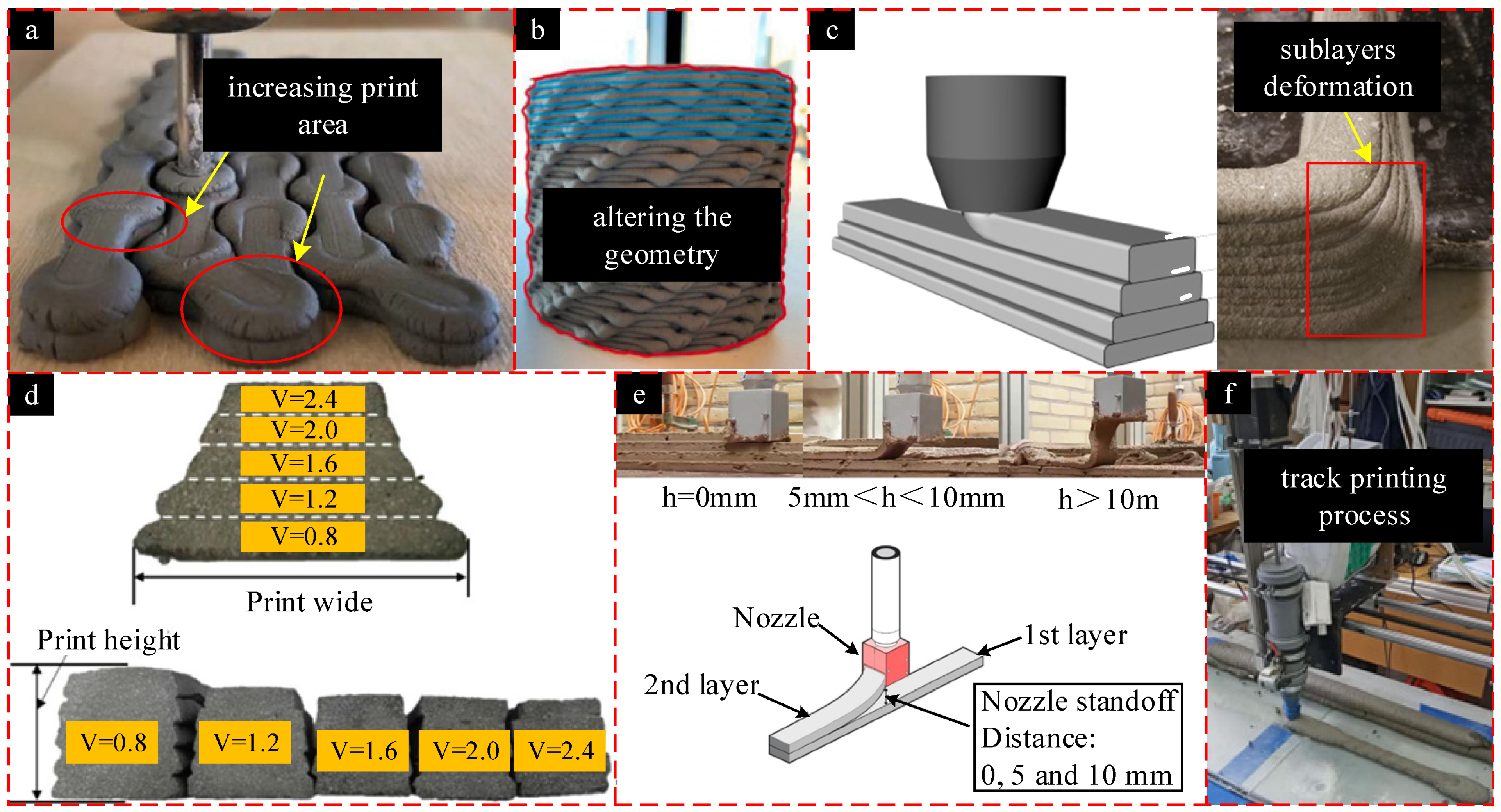
Figure 2.
Three-dimensional cement printing equipment. (a) Three-dimensional concrete printing device, (b) Device structure, (c) Air source, (d) Ink cartridge, (e) Nozzle, (f) Control system.
Figure 2.
Three-dimensional cement printing equipment. (a) Three-dimensional concrete printing device, (b) Device structure, (c) Air source, (d) Ink cartridge, (e) Nozzle, (f) Control system.

Figure 3.
Influence of flow-rate of material and printing nozzle speed on molding. (a) Ideal state, (b) High flow-rate of material or low printing nozzle speed, (c) Low flow-rate of material or high printing nozzle speed, (d) Breakage state.
Figure 3.
Influence of flow-rate of material and printing nozzle speed on molding. (a) Ideal state, (b) High flow-rate of material or low printing nozzle speed, (c) Low flow-rate of material or high printing nozzle speed, (d) Breakage state.
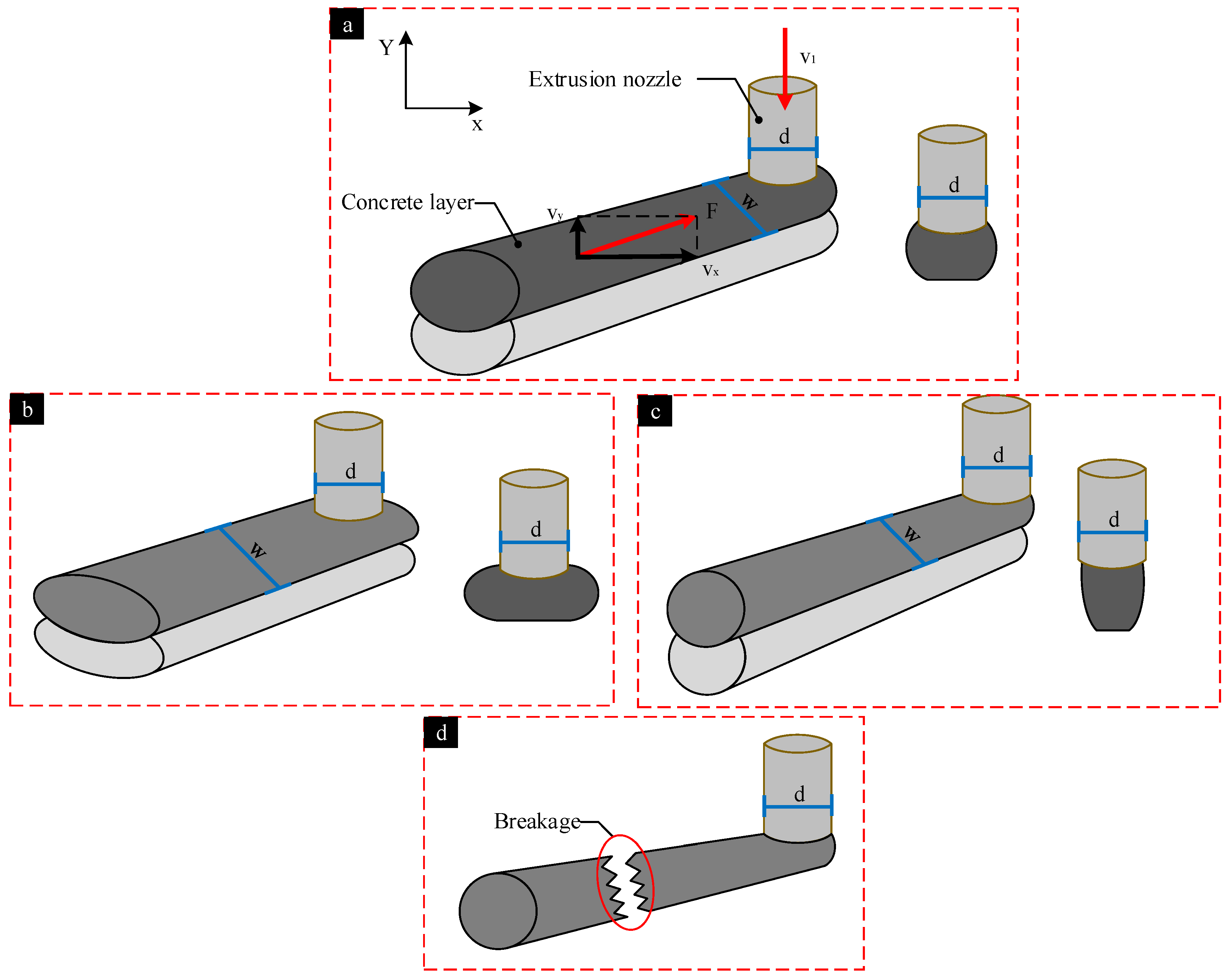
Figure 4.
Influence of nozzle offset on molding. (a) The nozzle offset is much higher than the nozzle diameter, (b) The nozzle offset is equal to the nozzle diameter, (c) The nozzle offset is much smaller than the nozzle diameter.
Figure 4.
Influence of nozzle offset on molding. (a) The nozzle offset is much higher than the nozzle diameter, (b) The nozzle offset is equal to the nozzle diameter, (c) The nozzle offset is much smaller than the nozzle diameter.

Figure 5.
Slump and strength test theoretical model. (a) Slump test, (b) The test process of strength.
Figure 5.
Slump and strength test theoretical model. (a) Slump test, (b) The test process of strength.

Figure 6.
The test process. (a) Slump, (b) Strength.
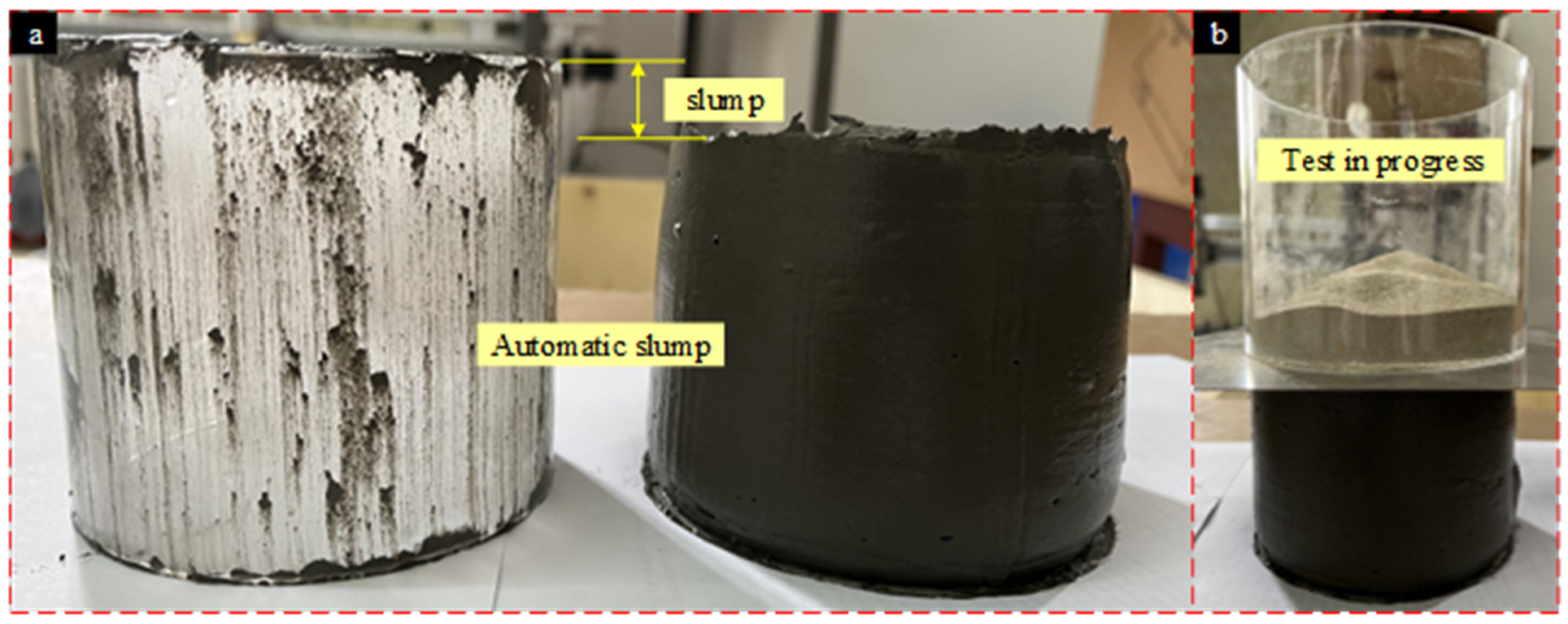
Figure 7.
Variation of strength and slump (n = 8). (a) Variation of strength and slump with tailing sand content, (b) Variation of strength and slump with time.
Figure 7.
Variation of strength and slump (n = 8). (a) Variation of strength and slump with tailing sand content, (b) Variation of strength and slump with time.
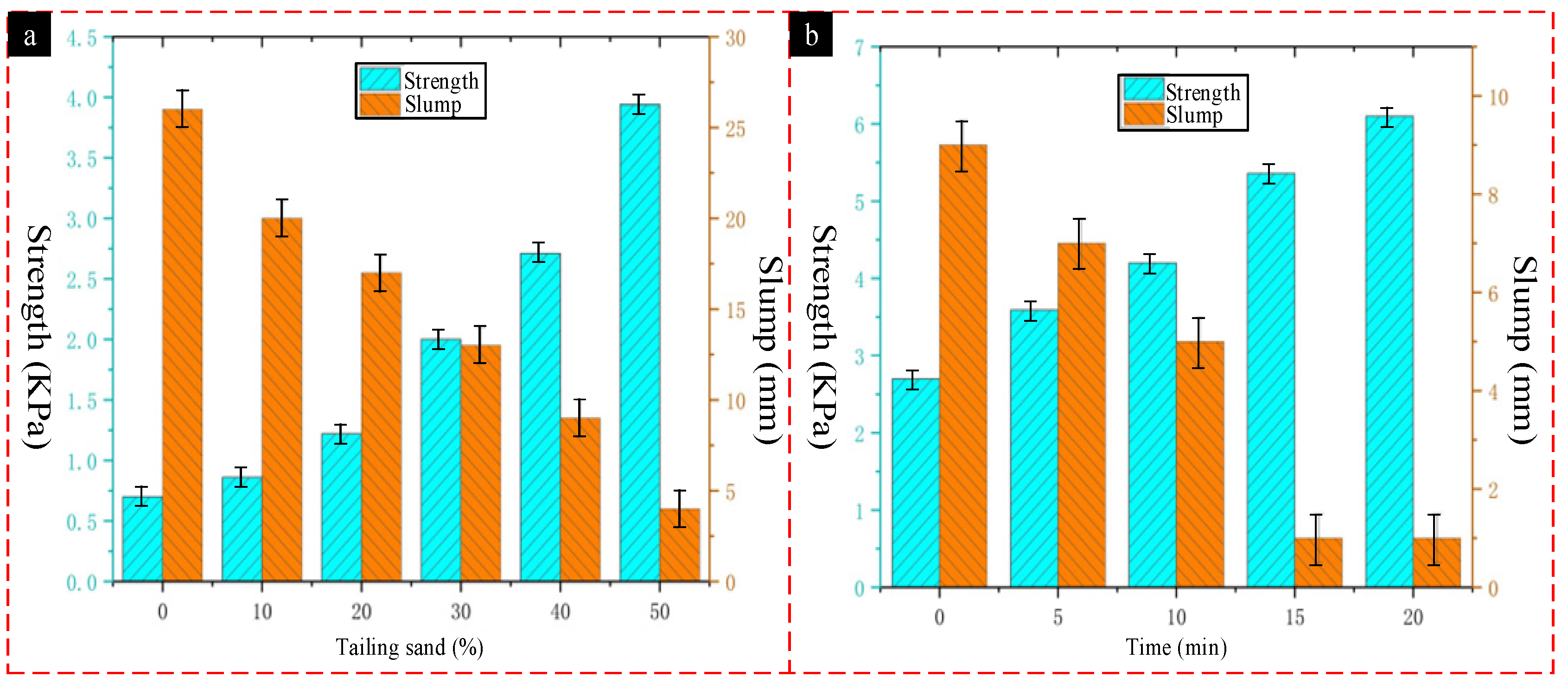
Figure 8.
Cement-based material molding relationship. (a) Variation of layer height and wide with nozzle speed under the same pressure, (b) Variation of layer height and wide with pressure under the same nozzle speed.
Figure 8.
Cement-based material molding relationship. (a) Variation of layer height and wide with nozzle speed under the same pressure, (b) Variation of layer height and wide with pressure under the same nozzle speed.
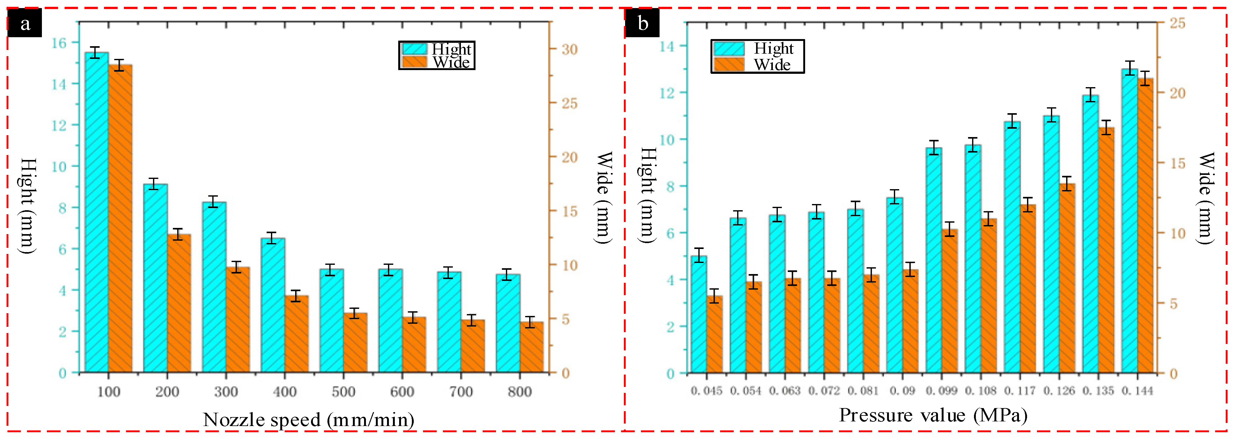
Figure 9.
Printing effect of cement-based material under different parameters. (a) Shapes at low speed and high pressure, (b) Shape under the best matching parameters, (c) Shape at high speed and low pressure, (d) Printing molding effect under low speed and high pressure, (e) Printing molding effect under the best matching parameters, (f) Printing molding effect under high speed and low pressure.
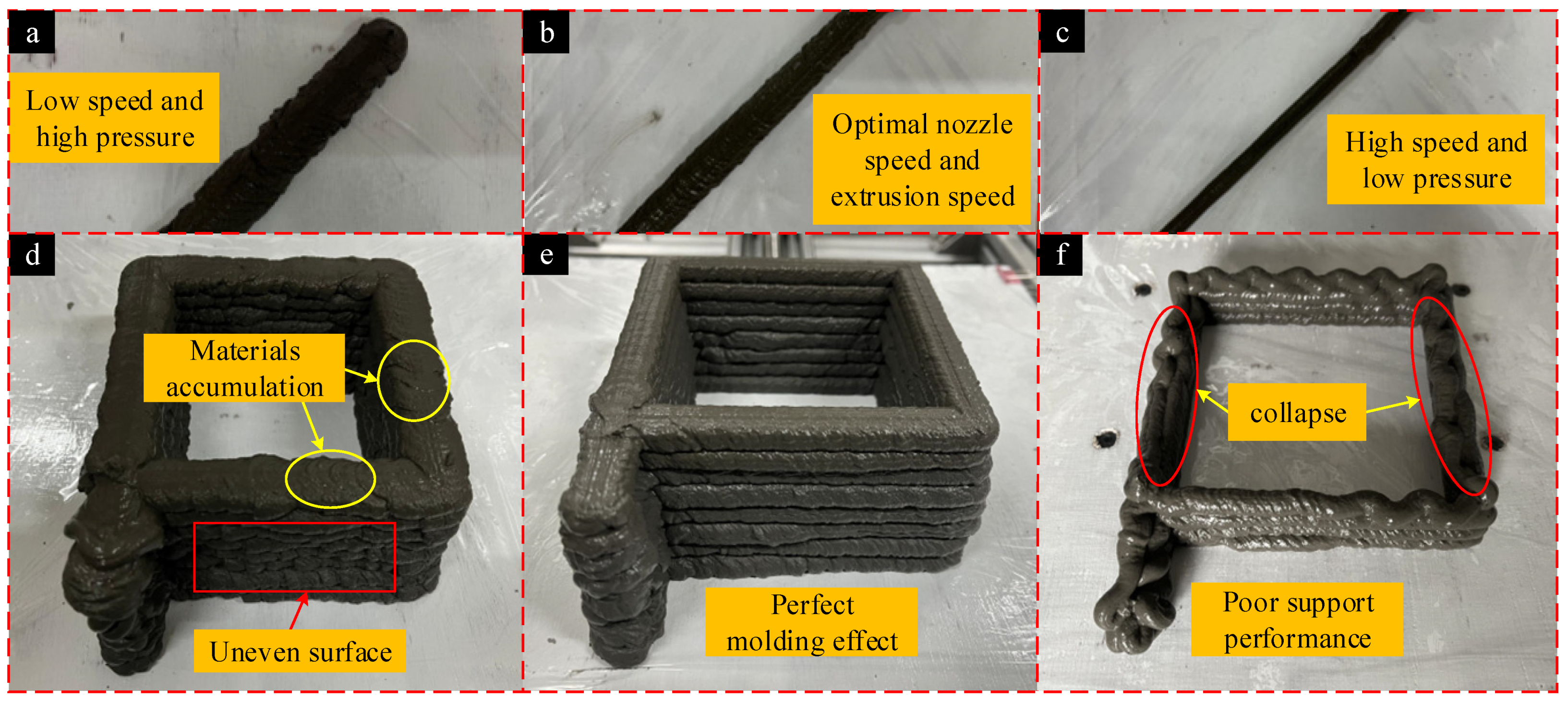
Figure 10.
Effect of nozzle offset on layer height and layer width.
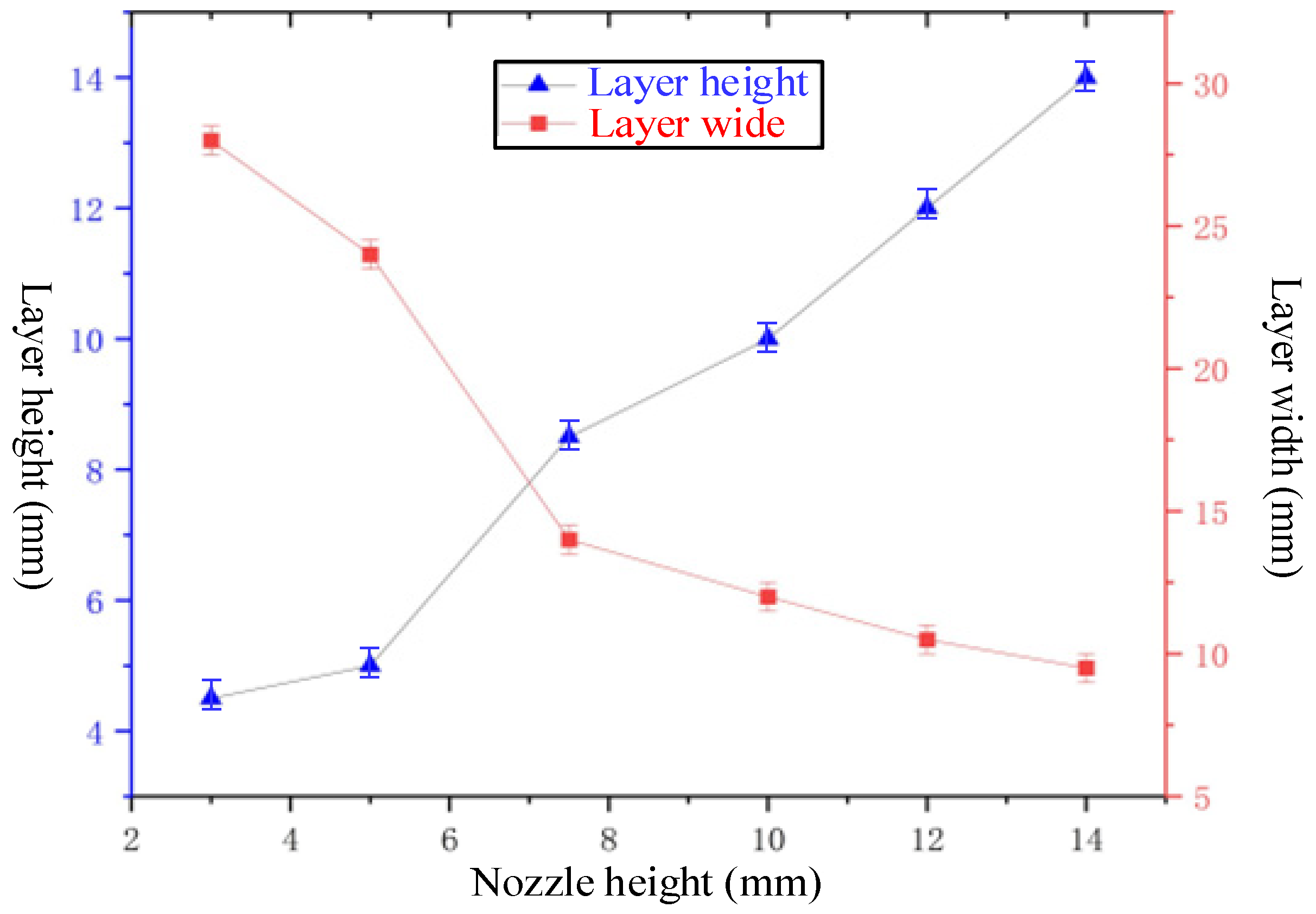
Figure 11.
Printing effect of cement-based material under different nozzle offset. (a) Width of the print layer when the nozzle offset is 3 mm, (b) Width of the print layer when the nozzle offset is 7.5 mm, (c) Width of the print layer when the nozzle offset is 12 mm, (d) Height of the print layer when the nozzle offset is 3 mm, (e) Height of the print layer when the nozzle offset is 7.5 mm, (f) Height of the print layer when the nozzle offset is 12 mm.
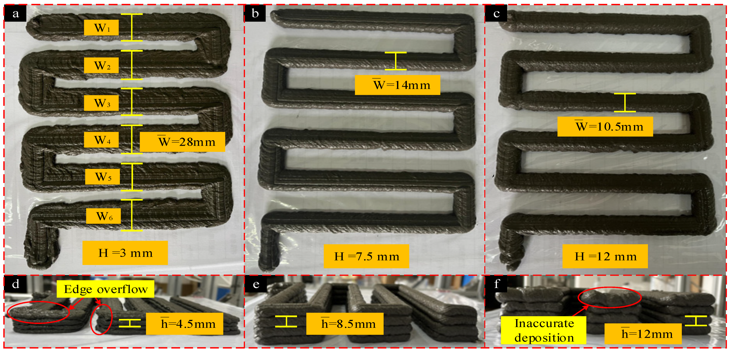
Figure 12.
Multi-nozzle extrusion printing effect. (a) Double nozzle printing, (b) Three nozzle printing.
Figure 12.
Multi-nozzle extrusion printing effect. (a) Double nozzle printing, (b) Three nozzle printing.

Table 1.
Physical properties of tailing sand.
| Fine Aggregate | Fineness Modulus | Average Particle Size (mm) | Bulk Density (kg/m3) | Mud Content (%) |
|---|---|---|---|---|
| Tailing sand | 0.7 | 0.15 | 1400 | 0.4 |
| Admixture | Fineness (45 micron standard sieve) | Average particle size (µm) | Density (g/cm3) | Water content (%) |
| Fly ash | ≤5% | 5 | 2.6 | ≤1 |
| Slag powder | ≤3% | 38 | 2.8 | ≤1 |
| Silicon powder | ≤3% | 5 | 2.6 | ≤3 |
Table 2.
Experimental material parameters.
| Tailing Sand/% | Water/Cement Ratio | Cement/% | Mineral Admixture/% | Thickener/% | Retarder/% |
|---|---|---|---|---|---|
| 0 | 0.39 | 80.2 | 19.8 | 0.05 | 0.3 |
| 10 | 0.39 | 80.2 | 19.8 | 0.05 | 0.3 |
| 20 | 0.39 | 80.2 | 19.8 | 0.05 | 0.3 |
| 30 | 0.39 | 80.2 | 19.8 | 0.05 | 0.3 |
| 40 | 0.39 | 80.2 | 19.8 | 0.05 | 0.3 |
| 50 | 0.39 | 80.2 | 19.8 | 0.05 | 0.3 |
Table 3.
3D printing system specifications.
| Parameters | Value |
|---|---|
| Size specification (X × Y × Z) | 800 × 800 × 600 mm3 |
| Walking accuracy | ±1 mm |
| Print speed | 0–3000 mm/min |
| Pressure range | 0–1.0 MPa |
Table 4.
Different nozzle speed under the same pressure.
| Number | Nozzle Speed (mm/s) | Pressure Value (MPa) | Number | Nozzle Speed (mm/s) | Pressure Value (MPa) |
|---|---|---|---|---|---|
| 1 | 1.667 | 0.045 | 5 | 8.333 | 0.045 |
| 2 | 3.333 | 0.045 | 6 | 10 | 0.045 |
| 3 | 5 | 0.045 | 7 | 11.667 | 0.045 |
| 4 | 6.667 | 0.045 | 8 | 13.333 | 0.045 |
Table 5.
Different pressure at the same nozzle speed.
| Number | Pressure Value (MPa) | Nozzle Speed (mm/s) | Number | Pressure Value (MPa) | Nozzle Speed (mm/s) |
|---|---|---|---|---|---|
| 1 | 0.045 | 8.333 | 7 | 0.099 | 8.333 |
| 2 | 0.054 | 8.333 | 8 | 0.108 | 8.333 |
| 3 | 0.063 | 8.333 | 9 | 0.117 | 8.333 |
| 4 | 0.072 | 8.333 | 10 | 0.126 | 8.333 |
| 5 | 0.081 | 8.333 | 11 | 0.135 | 8.333 |
| 6 | 0.09 | 8.333 | 12 | 0.144 | 8.333 |
Table 6.
Different nozzle offset at the same nozzle diameter.
| Number | Nozzle Offset (mm) | Nozzle Diameter (mm) | Number | Nozzle Offset (mm) | Nozzle Diameter (mm) |
|---|---|---|---|---|---|
| 1 | 3 | 10 | 4 | 10 | 10 |
| 2 | 5 | 10 | 5 | 12 | 10 |
| 3 | 7.5 | 10 | 6 | 14 | 10 |
Publisher’s Note: MDPI stays neutral with regard to jurisdictional claims in published maps and institutional affiliations. |
© 2022 by the authors. Licensee MDPI, Basel, Switzerland. This article is an open access article distributed under the terms and conditions of the Creative Commons Attribution (CC BY) license (https://creativecommons.org/licenses/by/4.0/).
Share and Cite
MDPI and ACS Style
Li, Z.; Liu, H.; Cheng, X.; Nie, P.; Yang, X.; Zheng, G.; Su, H.; Jin, W. Improvement of 3D Printing Cement-Based Material Process: Parameter Experiment and Analysis. Coatings 2022, 12, 1973. https://doi.org/10.3390/coatings12121973
AMA Style
Li Z, Liu H, Cheng X, Nie P, Yang X, Zheng G, Su H, Jin W. Improvement of 3D Printing Cement-Based Material Process: Parameter Experiment and Analysis. Coatings. 2022; 12(12):1973. https://doi.org/10.3390/coatings12121973
Chicago/Turabian StyleLi, Zihan, Huanbao Liu, Xiang Cheng, Ping Nie, Xianhai Yang, Guangming Zheng, Hongxing Su, and Wenyu Jin. 2022. "Improvement of 3D Printing Cement-Based Material Process: Parameter Experiment and Analysis" Coatings 12, no. 12: 1973. https://doi.org/10.3390/coatings12121973
Note that from the first issue of 2016, this journal uses article numbers instead of page numbers. See further details here.