
Research on the Vibration Characteristics of Aviation Hydraulic Clamp and Pipeline Based on Hard Coating

Abstract
:1. Introduction
2. Materials and Methods
2.1. Selection and Preparation of Test Materials
- (1)
- YSZ (8%Y2O3-ZrO2) (Beijing Chemical Company, Beijing, China) ceramic coating. Ceramic coatings have a high melting point and good stability at high temperatures and a thermal expansion coefficient similar to that of metal materials. Since the state of the pure ZrO2 coating itself is unstable and cannot be used as a thermal barrier coating, ZrO2 with the addition of Y2O3 was selected as the coating material. Generally, the content of Y2O3 in zirconia used as a thermal barrier coating is between 6 wt% and 8 wt%. This YSZ coating is currently the material most widely used in thermal barrier coatings, and offers good stability, corrosion resistance, and a high thermal cycle life.
- (2)
- Al-Cu-Fe-Cr (Beijing Chemical Company, Beijing, China) quasicrystalline coating. Quasicrystals have the properties of high hardness, oxidation resistance, and low thermal conductivity. However, due to their inherent high brittleness, they can only be attached to the surface of other substrates in the form of a film or a coating; thus, they are able to exert their outstanding mechanical and thermal properties while the substrate alleviates their brittleness. Professor Chungen Zhou of Beijing University of Aeronautics and Astronautics and others have used plasma spraying to prepare Al-Cu-Fe-Cr quasicrystalline coatings on titanium alloy substrates. After systematic research, they found that the quasicrystalline system had very good vibration damping performance.
- (3)
- YSZ-PTFE composite coating. PTFE (Fuxin Chemical Company, Fuxin, China) is a polytetrafluoroethylene-containing polymer chemical material with an excellent low-loss tangent and low dielectric constant. PTFE has a variety of properties, such as high-temperature resistance, corrosion resistance, and self-lubrication. This soft coating can effectively reduce the friction coefficient of surfaces onto which it is sprayed, improving the surface’s corrosion resistance. The combination of PTFE with a ceramic filler changes its material properties; PTFE can be mixed into a ceramic filler, following which it can be used as a damping material to absorb the vibration energy caused by external vibrations, thereby achieving the effect of vibration reduction and noise reduction. After many mixing–spraying experiments, YSZ and PTFE were finally mixed at a ratio of 16:1.
2.2. Design of the Test Plan
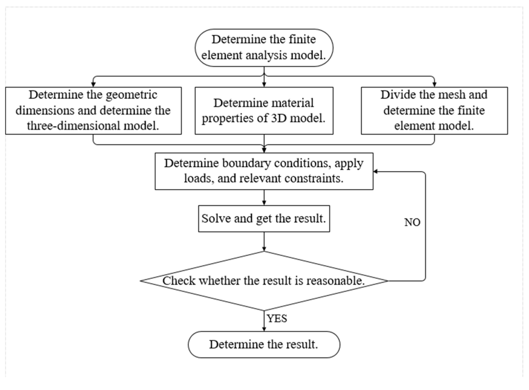
3. Establishment of a Hard-Coated Clamp-Piping Model Based on Finite Elements
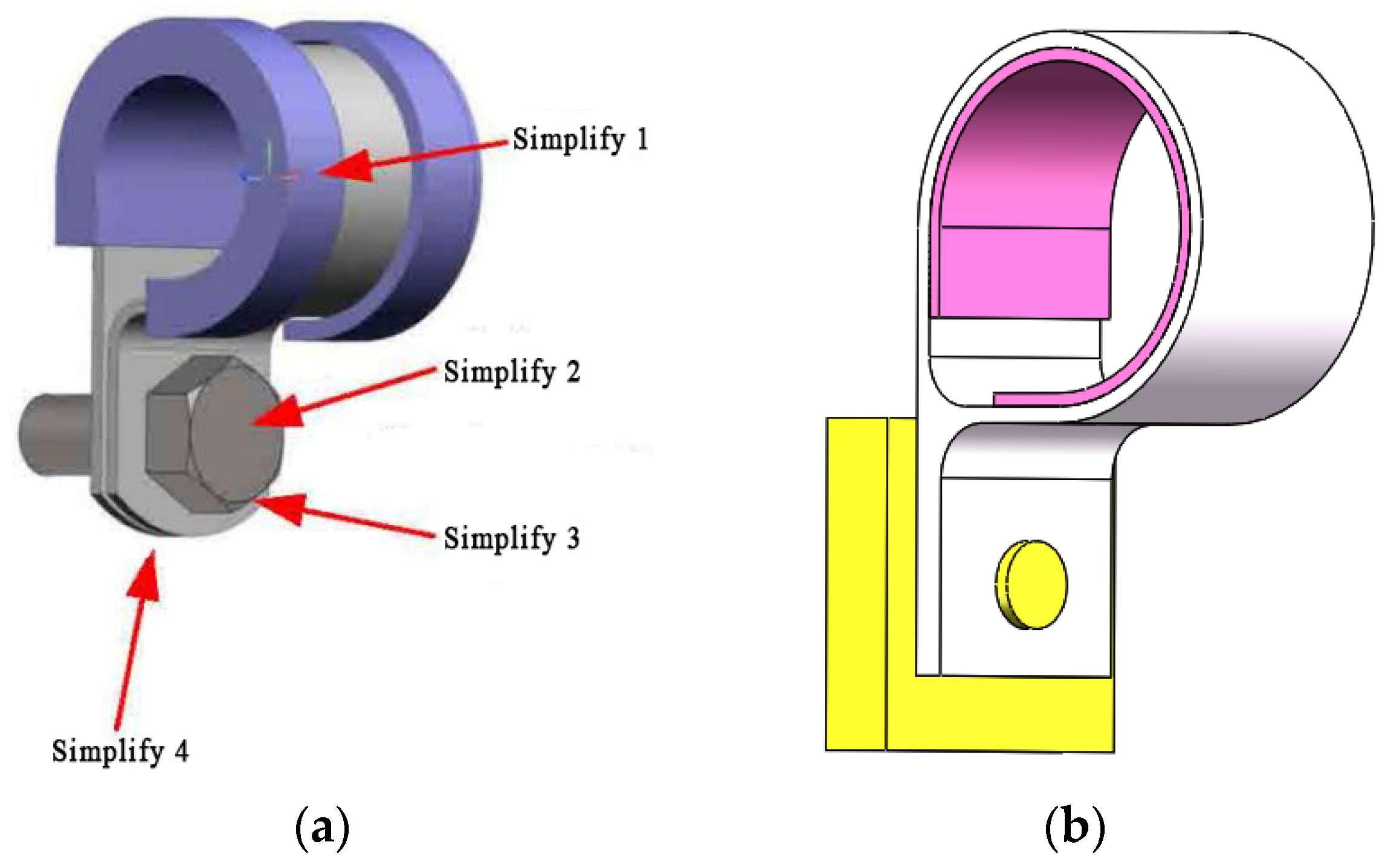
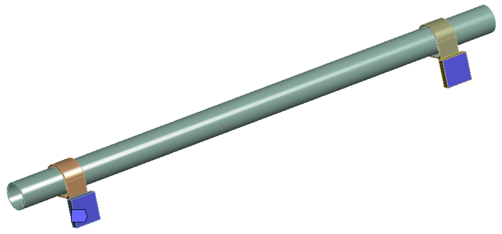
3.1. Straight Pipe-Clamp Model Establishment
3.2. Material Parameters
3.3. Mesh and Add Constraints
4. Clamp-Piping System Finite Element Modal Analysis and Vibration Test
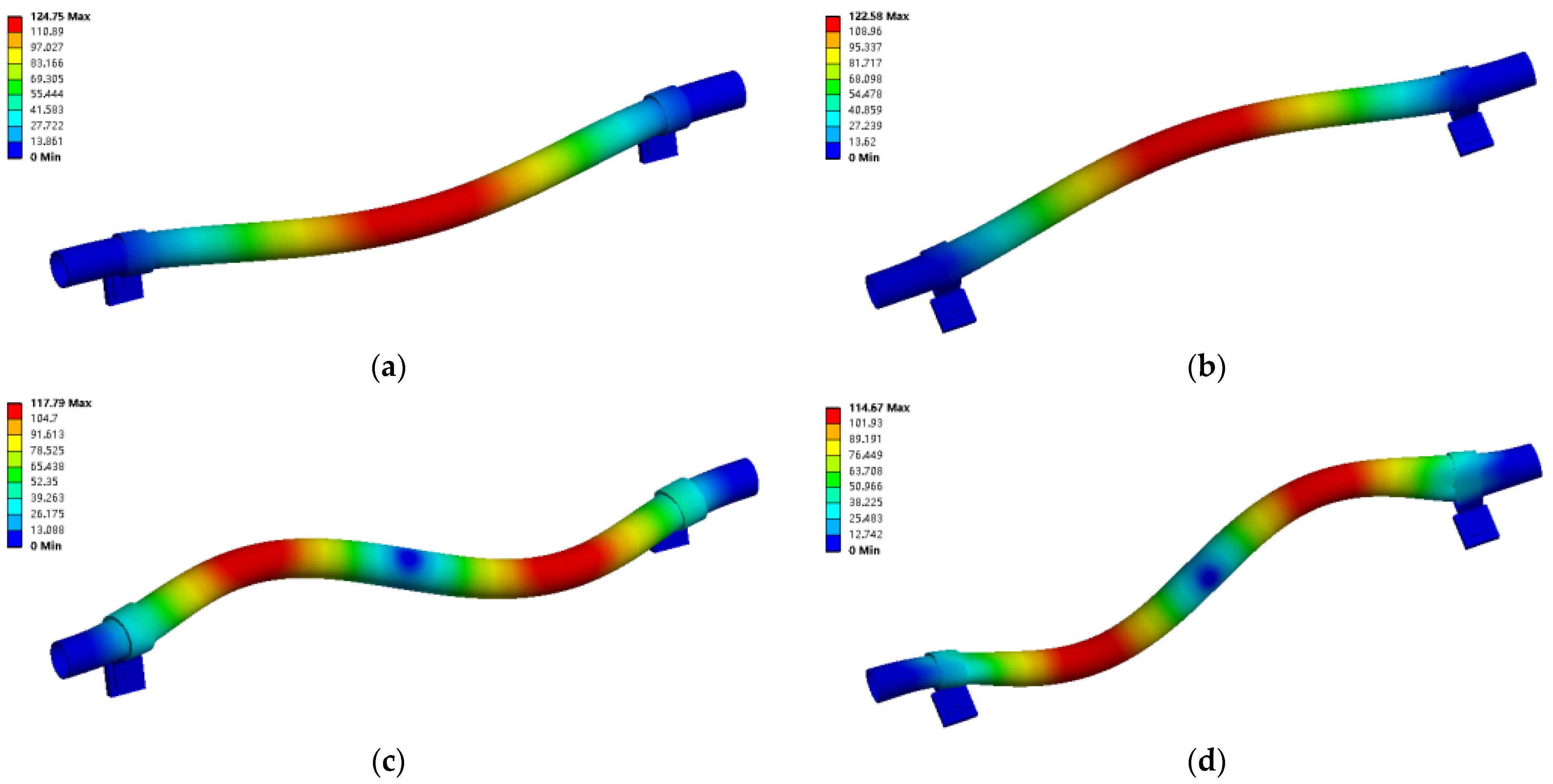
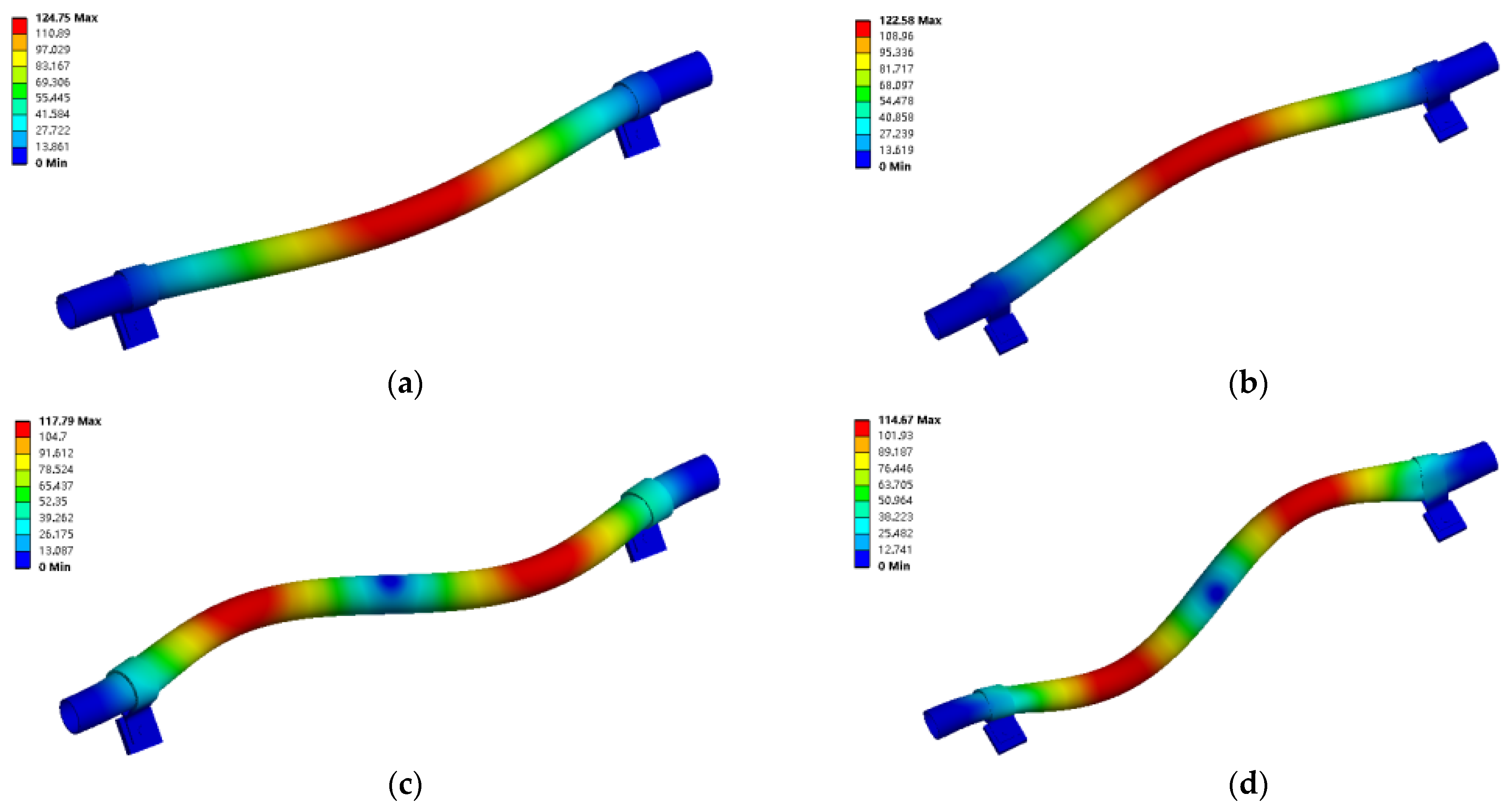
4.1. Finite Element Model Analysis
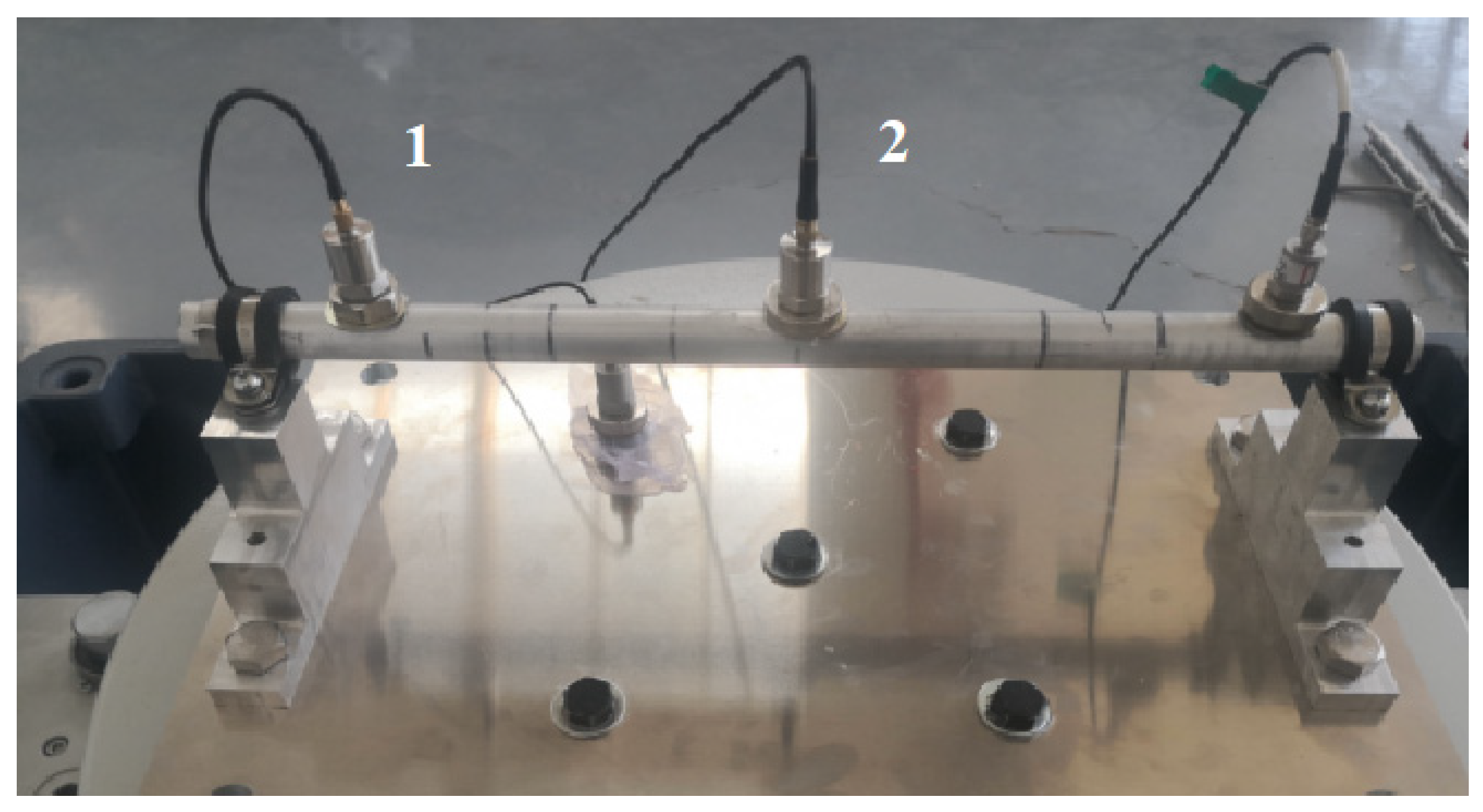
4.2. Clamp-Piping System Vibration Response Test
- (1)
- Test bench
- (2)
- Data acquisition and analysis system
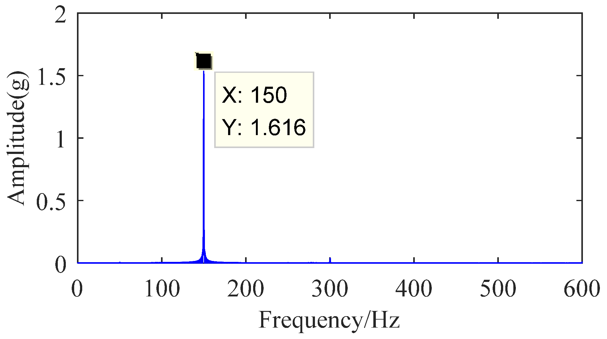
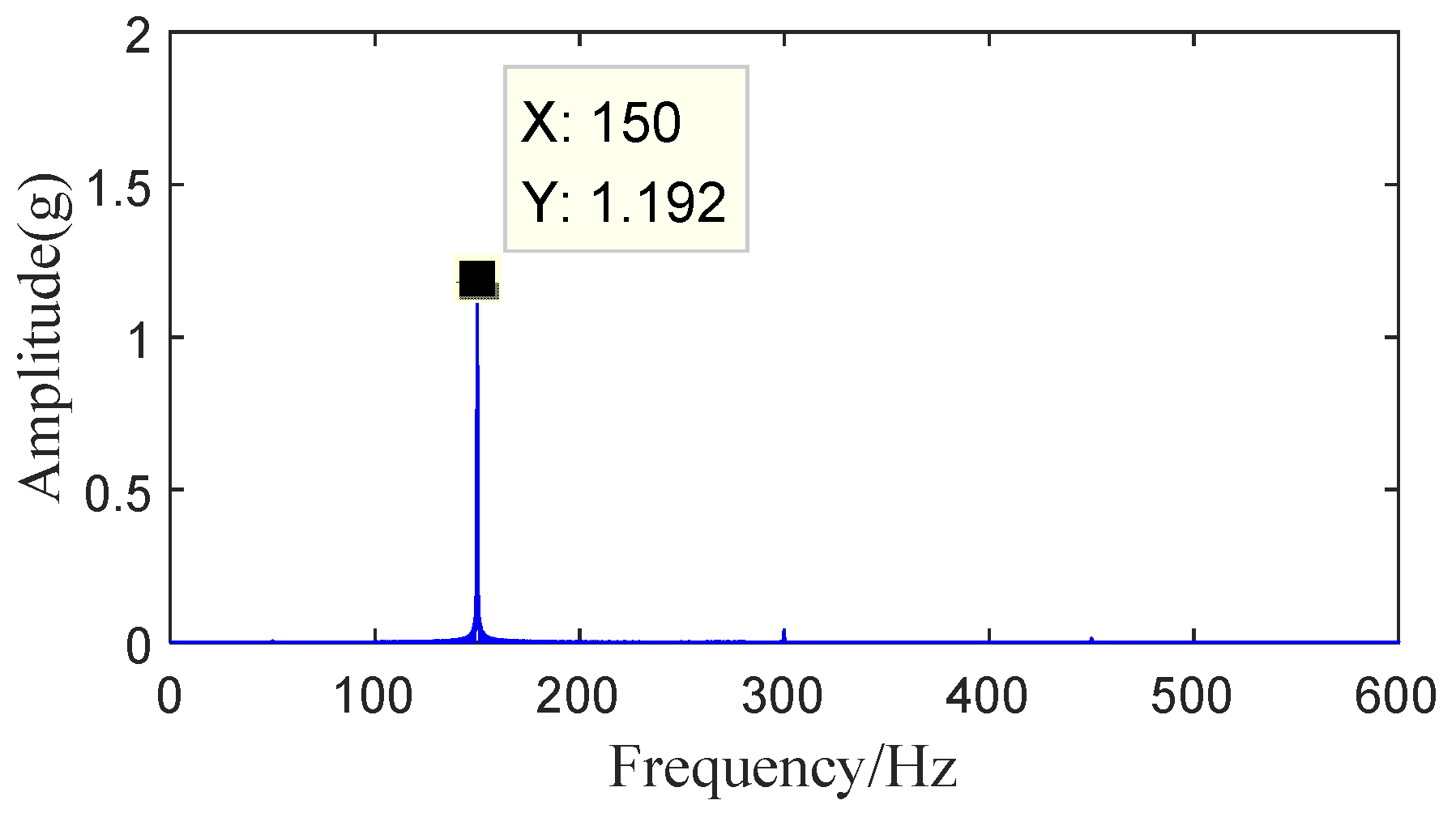
4.2.1. Fixed Frequency Vibration Test of Clamp-Piping System
4.2.2. Frequency Sweep Vibration Test of Clamp-Piping System
5. Conclusions
Author Contributions
Funding
Institutional Review Board Statement
Informed Consent Statement
Data Availability Statement
Acknowledgments
Conflicts of Interest
References
- Liu, D. Deliberation upon advance of aeroengine development in china. J. Aerosp. Power. 2001, 3, 1–7. [Google Scholar]
- Lin, J.; Zhou, E.; Du, L. Literature review on vibration mechanism and fault diagnosis of the pipe system of aero-engine. Mach. Tool Hydraul. 2013, 41, 163–164. [Google Scholar]
- Lin, J.; Zhao, Y.; Zhu, Q.; Han, S.; Ma, H.; Han, Q. Nonlinear Characteristic of Clamp Loosing in Aero-Engine Pipeline System. IEEE Access. 2021, 9, 64076–64084. [Google Scholar] [CrossRef]
- Gao, Y. Brief introduction and trend exploration of aero engine development. Mod. Manuf. Tech. Equip. 2018, 7, 222–224. [Google Scholar]
- Sheng, S. Research on influence of pipeline support parameters on vibration characteristics of hydraulic piping system. Master’s Thesis, Yanshan University, Qinhuangdao, China, March 2015. [Google Scholar]
- Zhao, S. Dynamic characteristics and fluid-structure coupling analysis of aero-engine external pipeline. Master’s Thesis, Nanjing University of Aeronautics and Astronautics, Nanjing, China, March 2014. [Google Scholar]
- Stosiak, M. The impact of hydraulic systems on the human being and the environment. J. Theor. Appl. Mech. 2015, 53, 409–420. [Google Scholar] [CrossRef] [Green Version]
- Stosiak, M. Vibration insulation of hydraulic system control components. Arch. Civ. Mech. 2011, 11, 237–248. [Google Scholar] [CrossRef]
- Gao, F.; Li, B.; Liu, X. Passive Vibration Reduction Analysis of the Mistuned Blisk Deposited Hard Coating Using Modified Reduced-Order Model. Coatings 2019, 9, 812. [Google Scholar] [CrossRef] [Green Version]
- Cross, K.R.; Lull, W.R.; Newman, R.L.; Cavanagh, J.R. Potential of graded coatings in vibration damping. J. Aircr. 1973, 10, 689–691. [Google Scholar] [CrossRef]
- Patsias, S.; Tomilnson, G.R.; Jones, A.M. Initial studies into hard coatings for fan blade damping. In Proceedings of the 6th National Turbine Engine High Cycle Fatigue, Sheffield, South Yorkshire, UK, 1 April 2001. [Google Scholar]
- Guangyu, D.; Zhen, T.; Dechun, B.; Kun, L.; Wei, S.; Qingkai, H. Damping properties of a novel porous Mg-Al alloy coating prepared by arc ion plating. Surf. Coat. Technol. 2014, 238, 139–142. [Google Scholar] [CrossRef]
- Yin, Z.; Chen, Y. Finite element analysis and experimental measurement of stiffness of hoop. J. Aerosp. Power 1999, 14, 179–182. [Google Scholar]
- Kwong, A.H.M.; Edge, K.A. Structure-borne noise prediction in liquid-coneying pipe systems. Proc. Inst. Mech. Eng.-Part I 1996, 210, 189–200. [Google Scholar]
- Kwong, A.H.M.; Edge, K.A. Method to reduce noise in hydraulic systems by optimizing pipe clamp locations. Proc. Inst. Mech. Eng.-Part I 1998, 212, 267–280. [Google Scholar] [CrossRef]
- Du, G.Y. Damping properties of arc ion plating NiCrAlY coating with vacuum annealing. Coatings 2018, 8, 20. [Google Scholar] [CrossRef] [Green Version]
- Bonetti, E. Damping behavior of layered aluminium and aluminide coatings on AISI 316 austenitic steel. Coatings 2020, 10, 888. [Google Scholar] [CrossRef]
- Al-Rub, R.K.A.; Palazotto, A.N. Mesoscale energy dissipation prediction in thermal barrier ceramic coatings under nonlinear vibration. In Proceedings of the 51st AIAA/ASME/ASCE/AHS/ASC Structures, Structural Dynamics, and Materials Conference AIAA/ASME/ASH Adaptive Structures Conference, Orlando, FL, USA, 12 April 2010. [Google Scholar]
- Patsias, S.; Saxton, C.; Shipton, M. Hard damping coatings: An experimental procedure for extraction of damping characteristics and modulus of elasticity. Mater. Sci. Eng. 2003, 370, 412–416. [Google Scholar] [CrossRef]
- Torvik, P.J.; Henderson, J.P. Influence of glass content on damping properties of plasma-sprayed mixtures of zirconia and glass. J. Mater. Eng. Perform. 2012, 21, 1405–1415. [Google Scholar] [CrossRef]
- Sun, J.; Kari, L. Coating methods to increase material damping of compressor blades: Measurements and modeling. Proceedings of Asme Turbo Expo: Power for Land, Sea, and Air, London, UK, 10 March 2011. [Google Scholar]
- Gao, J.; Gao, Y.; Yan, X.; Jiang, J.; Xu, K.; Sun, W. Damping mistuning effect of the hard-coating-based intentional mistuning techniques on mistuned blisks and its mechanism. Aerosp. Sci. Technol. 2020, 101, 105848. [Google Scholar] [CrossRef]
- Paimushin, V.N.; Firsov, V.A.; Shishkin, V.M. Numerical modeling of resonant vibrations of an elongate plate with an integral damping coating. Mech. Compos. 2020, 56, 149–168. [Google Scholar] [CrossRef]
- Zhang, L.; Zhou, J.; Yang, H.; Wang, X.; Cai, Z.; Zhu, M. Effect of modulation of interfacial properties on the tribological properties of viscoelastic epoxy resin damping coatings. Polym. Test. 2021, 100, 107229. [Google Scholar] [CrossRef]
- Lv, J. Research on dynamic characteristics of single-joint clamps for aero-engine external piping. Master’s Thesis, Nanjing University of Aeronautics and Astronautics, Nanjing, China, December 2018. [Google Scholar]
- Cui, L. Testing and Simulation of Mechanical Properties of Metal Rubber Materials. Master’s Thesis, North University of China, Taiyuan, China, April 2016. [Google Scholar]


| Factor Level | Coating Material A | Coating Thickness B (μm) | Clamp Material C |
|---|---|---|---|
| 1 | 8%Y2O3-ZrO2 | 100 | Galvanized iron |
| 2 | Al-Cu-Fe-Cr | 150 | 304 stainless steel |
| 3 | YSZ-PTFE | 200 |
| Test Number | Horizontal Combination | A | B (μm) | C |
|---|---|---|---|---|
| P1 | A1B1C1 | 1(8%Y2O3-ZrO2) | 1(100) | 1(Galvanized iron) |
| P2 | A1B2C2 | 1(8%Y2O3-ZrO2) | 2(150) | 2(304 stainless steel) |
| P3 | A1B3C2 | 1(8%Y2O3-ZrO2) | 3(200) | 2(304 stainless steel) |
| P4 | A2B1C2 | 2(Al-Cu-Fe-Cr) | 1(100) | 2(304 stainless steel) |
| P5 | A2B2C2 | 2(Al-Cu-Fe-Cr) | 2(150) | 2(304 stainless steel) |
| P6 | A2B3C1 | 2(Al-Cu-Fe-Cr) | 3(200) | 1(Galvanized iron) |
| P7 | A3B1C2 | 3(ZrO2-PTFE) | 1(100) | 2(304 stainless steel) |
| P8 | A3B2C1 | 3(ZrO2-PTFE) | 2(150) | 1(Galvanized iron) |
| P9 | A3B3C2 | 3(ZrO2-PTFE) | 3(200) | 2(304 stainless steel) |
| Part | Material | Elastic Modulus (Pa) | Poisson’s Ratio | Density (kg/m3) |
|---|---|---|---|---|
| Pipeline | Nitronic40 (XM-10) S21900 Stainless steel | 180 × 109 | 0.298 | 7830 |
| The first type of clamp | 304 stainless steel | 1.98 × 10⁹ | 0.3 | 7830 |
| Rubber liner | Rubber | 1 × 10⁹ | 0.49 | 930 |
| The second type of clamp | Galvanized steel | 2 × 10¹¹ | 0.31 | 7870 |
| Material | Elastic Modulus (Pa) | Poisson’s Ratio | Density(kg/m3) |
|---|---|---|---|
| 8%Y2O3-ZrO2 | 180 × 109 | 0.31 | 5850 |
| Al-Cu-Fe-Cr | 168 × 109 | 0.23 | 4492 |
| ZrO2-PTFE | 169.4 × 10⁹ | 0.32 | 5633 |
| 304 Stainless Steel Clamp-Pipeline Natural Frequency/Hz | Galvanized Steel Clamp-Pipeline Natural Frequency/Hz | |
|---|---|---|
| 1 | 488.62 | 487.65 |
| 2 | 692.59 | 692.71 |
| 3 | 1014.1 | 1013.6 |
| 4 | 1730.8 | 1730.1 |
| 5 | 1939.8 | 1939.8 |
| 6 | 2420.8 | 2421.2 |
| 7 | 3200.9 | 3202.8 |
| 8 | 3836.6 | 3835.6 |
| 9 | 4019 | 4019.9 |
| 10 | 4118.5 | 4117.2 |
| Thickness 100 (μm) | Offset Rate (%) | Thickness 150 (μm) | Offset Rate (%) | Thickness 200 (μm) | Offset Rate (%) | |
|---|---|---|---|---|---|---|
| 1 | 497.77 | 1.87% | 523.92 | 7.22% | 542.64 | 11.06% |
| 2 | 696.52 | 0.57% | 700.81 | 1.19% | 704.9 | 1.78% |
| 3 | 1019.1 | 0.49% | 1047.9 | 3.33% | 1072 | 5.71% |
| 4 | 1728.9 | −0.11% | 1735.9 | 0.29% | 1739.8 | 0.52% |
| 5 | 1941 | 0.06% | 1948.7 | 0.46% | 1955.3 | 0.80% |
| 6 | 2417.4 | −0.14% | 2431.3 | 0.43% | 2442.6 | 0.90% |
| 7 | 3208.6 | 0.24% | 3244.3 | 1.36% | 3271.6 | 2.21% |
| 8 | 3848.7 | 0.32% | 3873.7 | 0.97% | 3892.9 | 1.47% |
| 9 | 4020.5 | 0.04% | 4035.3 | 0.41% | 4048.4 | 0.73% |
| 10 | 4134.9 | 0.40% | 4171.8 | 1.29% | 4212.2 | 2.28% |
| Thickness 100 (μm) | Offset Rate (%) | Thickness 150 (μm) | Offset Rate (%) | Thickness 200 (μm) | Offset Rate (%) | |
|---|---|---|---|---|---|---|
| 1 | 497 | 1.92% | 523.34 | 7.32% | 542.15 | 11.18% |
| 2 | 696.61 | 0.56% | 700.87 | 1.18% | 704.94 | 1.77% |
| 3 | 1018.8 | 0.51% | 1047.5 | 3.34% | 1071.6 | 5.72% |
| 4 | 1728.3 | −0.10% | 1735.3 | 0.30% | 1739.2 | 0.53% |
| 5 | 1940.9 | 0.06% | 1948.7 | 0.46% | 1955.3 | 0.80% |
| 6 | 2418 | −0.13% | 2431.8 | 0.44% | 2443.1 | 0.90% |
| 7 | 3210.3 | 0.23% | 3245.9 | 1.35% | 3273 | 2.19% |
| 8 | 3847.9 | 0.32% | 3873.1 | 0.98% | 3892.5 | 1.48% |
| 9 | 4021.5 | 0.04% | 4036.3 | 0.41% | 4049.4 | 0.73% |
| 10 | 4133.4 | 0.39% | 4170.2 | 1.29% | 4210.4 | 2.26% |
| Parameter | Configuration | Parameter | Configuration |
|---|---|---|---|
| Reference sensitivity | 100 mv/g | Mounting thread | M5 |
| Frequency Range | 0.5–9000 | Resonant frequency | >25 KHz |
| Measuring range | 50 g | Resolution | 0.002 m/s2 |
| Weight | 10 g | Dimensions | 13 × 22 mm |
| Test Number | A | B (μm) | C |
|---|---|---|---|
| P1 | 1(8%Y2O3-ZrO2) | 1(100) | 1(Galvanized iron) |
| P2 | 1(8%Y2O3-ZrO2) | 2(150) | 2(304 stainless steel) |
| P3 | 1(8%Y2O3-ZrO2) | 3(200) | 2(304 stainless steel) |
| P4 | 2(Al-Cu-Fe-Cr) | 1(100) | 2(304 stainless steel) |
| P5 | 2(Al-Cu-Fe-Cr) | 2(150) | 2(304 stainless steel) |
| P6 | 2(Al-Cu-Fe-Cr) | 3(200) | 1(Galvanized iron) |
| P7 | 3(ZrO2-PTFE) | 1(100) | 2(304 stainless steel) |
| P8 | 3(ZrO2-PTFE) | 2(150) | 1(Galvanized iron) |
| P9 | 3(ZrO2-PTFE) | 3(200) | 2(304 stainless steel) |
| P10 | 304 stainless steel | ||
| P11 | Galvanized iron |
| Test Number | A Coating Material | B Coating Thickness (μm) | C Clamp Material | Damping Rate |
|---|---|---|---|---|
| P1 | 1(8%Y2O3-ZrO2) | 1(100) | 1(Galvanized iron) | 3.22% |
| P2 | 1(8%Y2O3-ZrO2) | 2(150) | 2(304 stainless steel) | 7.17% |
| P3 | 1(8%Y2O3-ZrO2) | 3(200) | 2(304 stainless steel) | 17.79% |
| P4 | 2(Al-Cu-Fe-Cr) | 1(100) | 2(304 stainless steel) | 1.59% |
| P5 | 2(Al-Cu-Fe-Cr) | 2(150) | 2(304 stainless steel) | 10.41% |
| P6 | 2(Al-Cu-Fe-Cr) | 3(200) | 1(Galvanized iron) | 16.71% |
| P7 | 3(ZrO2-PTFE) | 1(100) | 2(304 stainless steel) | 4.28% |
| P8 | 3(ZrO2-PTFE) | 2(150) | 1(Galvanized iron) | 12.93% |
| P9 | 3(ZrO2-PTFE) | 3(200) | 2(304 stainless steel) | 21.45% |
| P10 | 304 stainless steel | |||
| P11 | Galvanized iron | |||
| Sum value K1 | 28.18% | 9.09% | 32.86% | |
| Sum value K2 | 28.71% | 30.51% | 62.69% | |
| Sum value K3 | 38.66% | 55.95% | ||
| Mean K1 | 9.39% | 3.03% | 12.37% | |
| Mean K2 | 9.57% | 10.17% | 13.43% | |
| Mean K3 | 12.89% | 18.65% | ||
| Extremum R | 3.32% | 15.62% | 1.07% | |
| Excellent solution | A3 | B3 | C2 |
| Test Number | A Coating Material | B Coating Thickness (μm) | C Clamp Material | Damping Rate |
|---|---|---|---|---|
| P1 | 1(8%Y2O3-ZrO2) | 1(100) | 1(Galvanized iron) | 3.83% |
| P2 | 1(8%Y2O3-ZrO2) | 2(150) | 2(304 stainless steel) | 13.82% |
| P3 | 1(8%Y2O3-ZrO2) | 3(200) | 2(304 stainless steel) | 23.06% |
| P4 | 2(Al-Cu-Fe-Cr) | 1(100) | 2(304 stainless steel) | 2.18% |
| P5 | 2(Al-Cu-Fe-Cr) | 2(150) | 2(304 stainless steel) | 10.69% |
| P6 | 2(Al-Cu-Fe-Cr) | 3(200) | 1(Galvanized iron) | 17.99% |
| P7 | 3(ZrO2-PTFE) | 1(100) | 2(304 stainless steel) | 3.16% |
| P8 | 3(ZrO2-PTFE) | 2(150) | 1(Galvanized iron) | 16.73% |
| P9 | 3(ZrO2-PTFE) | 3(200) | 2(304 stainless steel) | 24.67% |
| P10 | 304 stainless steel | |||
| P11 | Galvanized iron | |||
| Sum value K1 | 40.71% | 9.17% | 38.55% | |
| Sum value K2 | 30.86% | 41.24% | 77.58% | |
| Sum value K3 | 44.56% | 65.72% | ||
| Mean K1 | 13.57% | 3.06% | 12.37% | |
| Mean K2 | 11.73% | 13.75% | 13.43% | |
| Mean K3 | 15.00% | 21.91% | ||
| Extremum R | 3.27% | 18.85% | 1.07% | |
| Excellent solution | A3 | B3 | C2 |
| Comparison of Simulation and Experiment Under 150 Hz Excitation | |||
| Test Number | 150 Hz Vibration Experimental Sensor Vibration Acceleration Amplitude (g) | 150 Hz Vibration Simulation Vibration Acceleration Amplitude (g) | Error Rate |
| P1 | 1.564 | 1.485 | 5.05% |
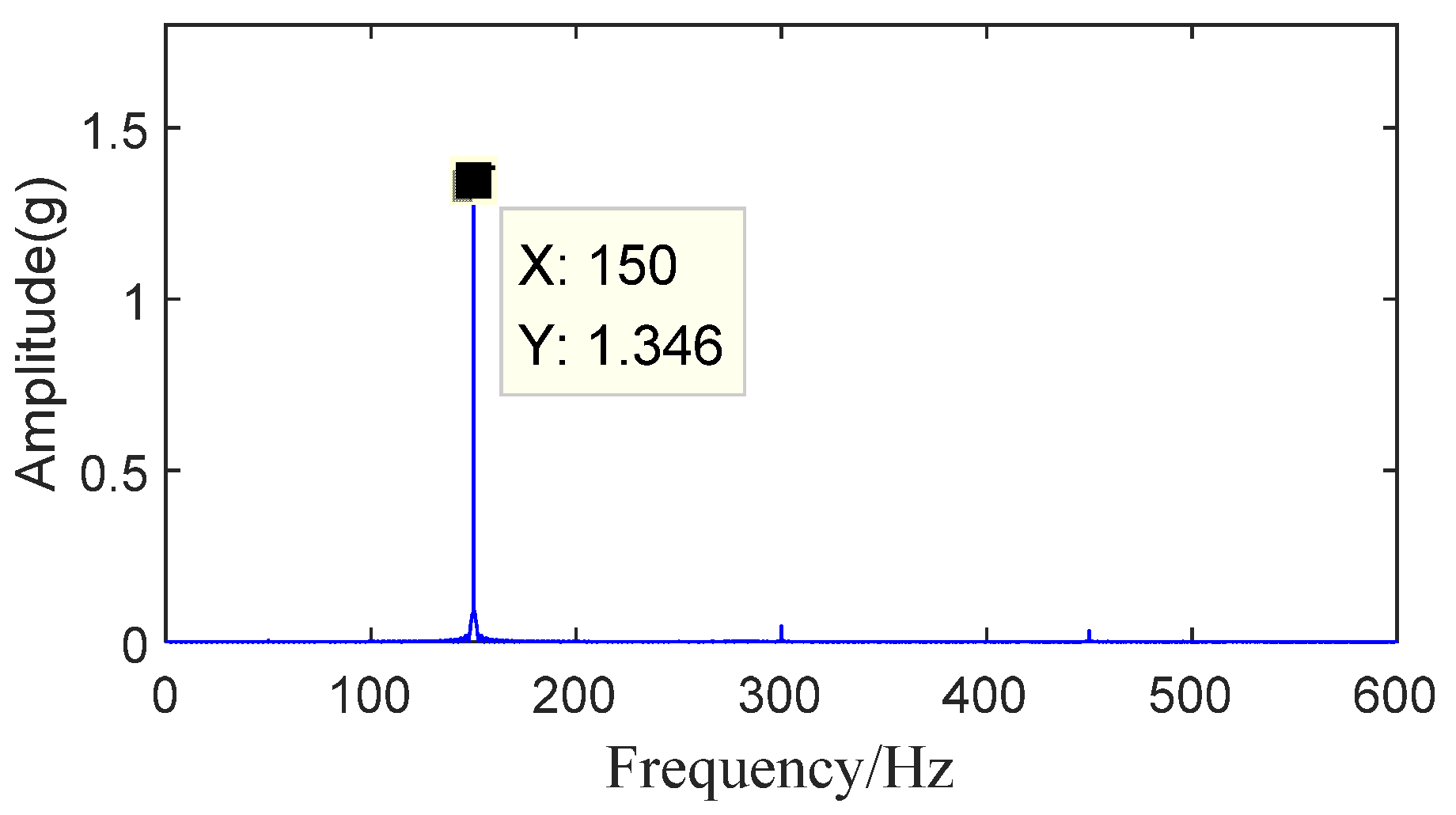
| P2 | 1.346 | 1.288 | 4.31% |
| P3 | 1.192 | 1.183 | 0.76% |
| P4 | 1.427 | 1.477 | −3.50% |
| P5 | 1.299 | 1.314 | −1.15% |
| P6 | 1.346 | 1.276 | 5.20% |
| P7 | 1.388 | 1.439 | −3.67% |
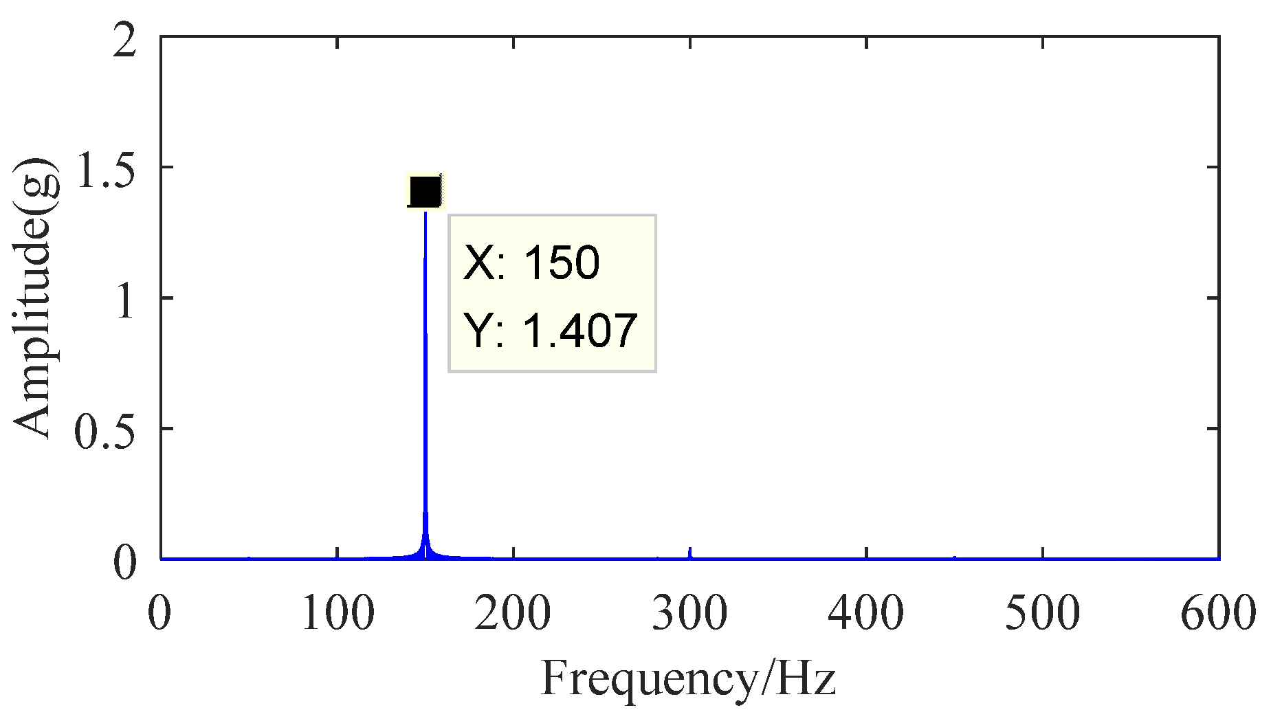
| P8 | 1.407 | 1.308 | 7.04% |
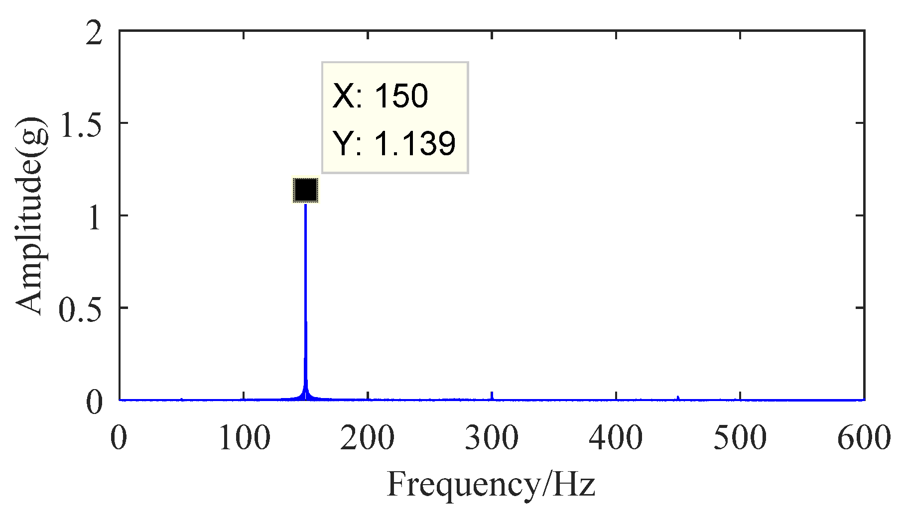
| P9 | 1.139 | 1.136 | 0.26% |
| P10 | 1.450 | 1.494 | −3.03% |
| P11 | 1.616 | 1.504 | 6.93% |
| Comparison of Simulation and Experiment under 200 Hz Excitation | |||
| Test Number | 200 Hz vibration Experimental Sensor Vibration Acceleration Amplitude (g) | 200 Hz Vibration Simulation Vibration Acceleration Amplitude (g) | Error Rate |
| P1 | 2.912 | 2.857 | 1.89% |
| P2 | 2.564 | 2.454 | 4.29% |
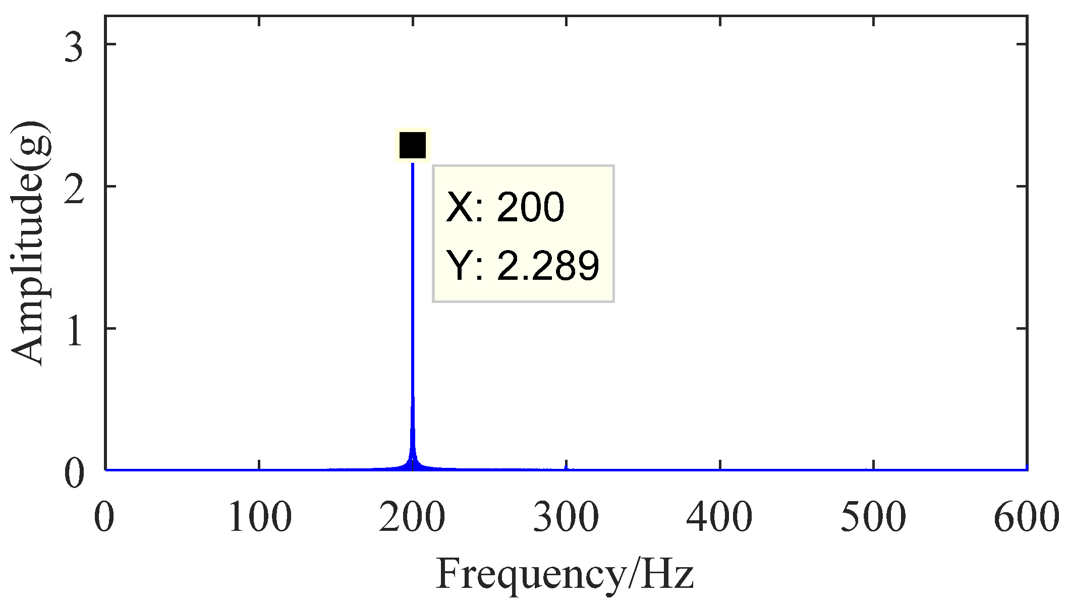
| P3 | 2.289 | 2.241 | 2.10% |
| P4 | 2.910 | 2.882 | 0.96% |
| P5 | 2.657 | 2.506 | 5.68% |
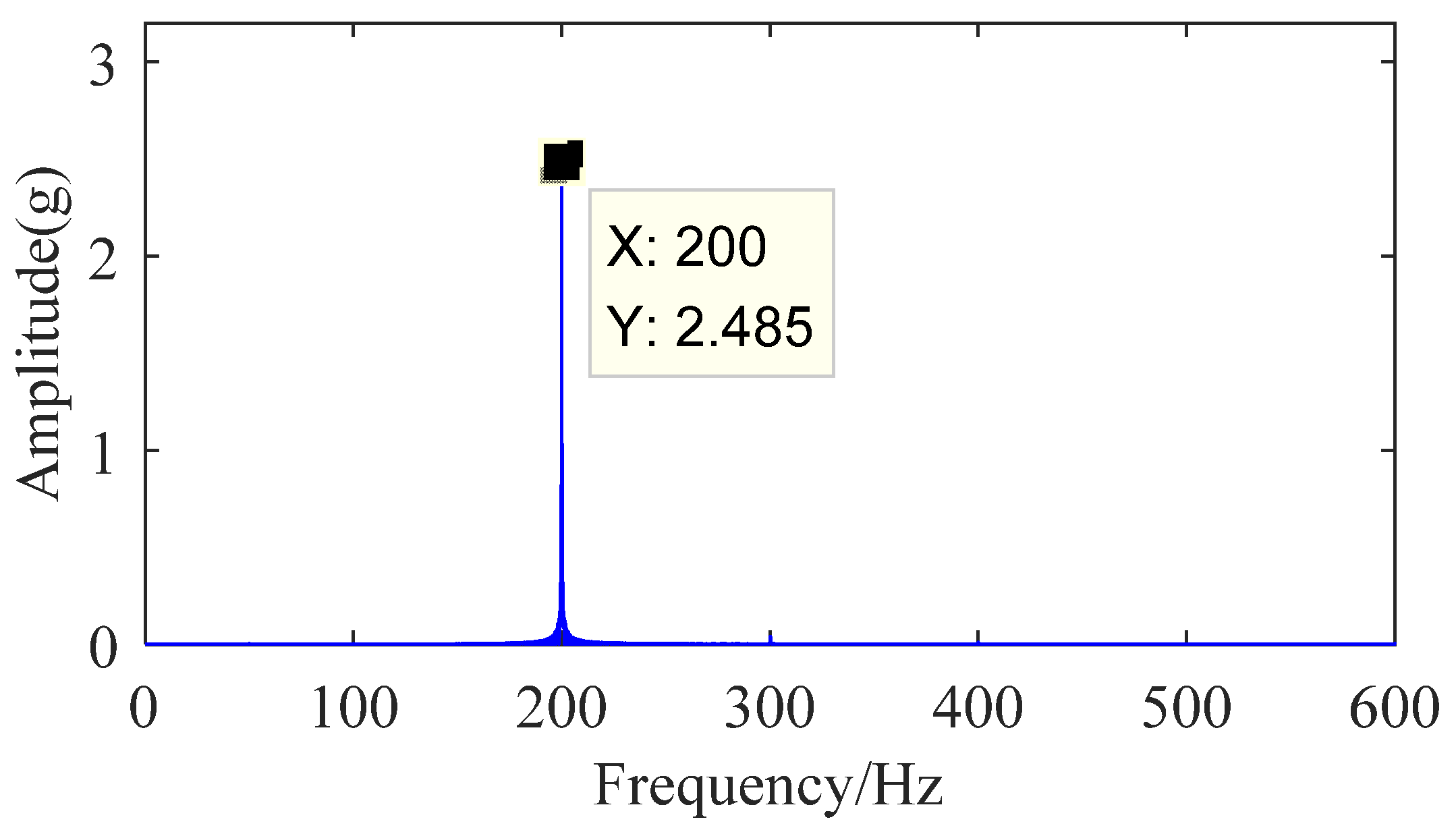
| P6 | 2.485 | 2.306 | 7.20% |
| P7 | 2.881 | 2.863 | 0.62% |
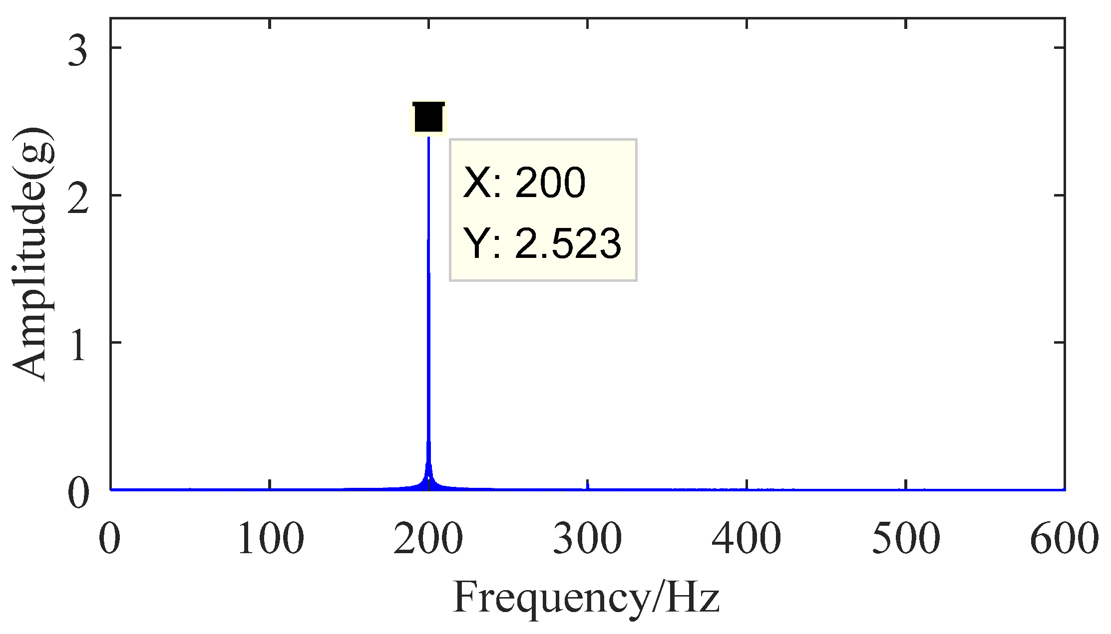
| P8 | 2.523 | 2.494 | 1.15% |
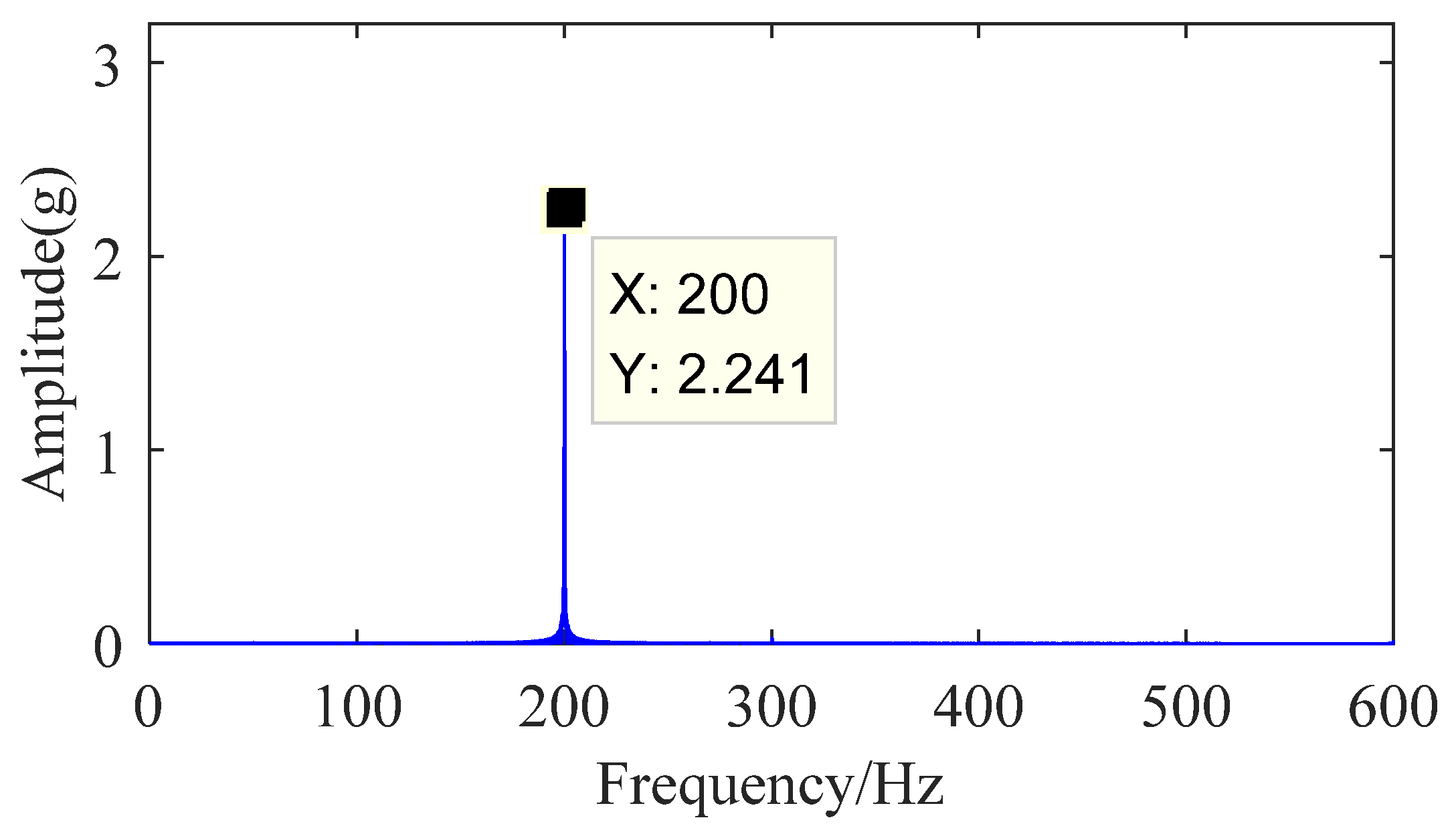
| P9 | 2.241 | 2.273 | −1.43% |
| P10 | 2.975 | 2.884 | 3.06% |
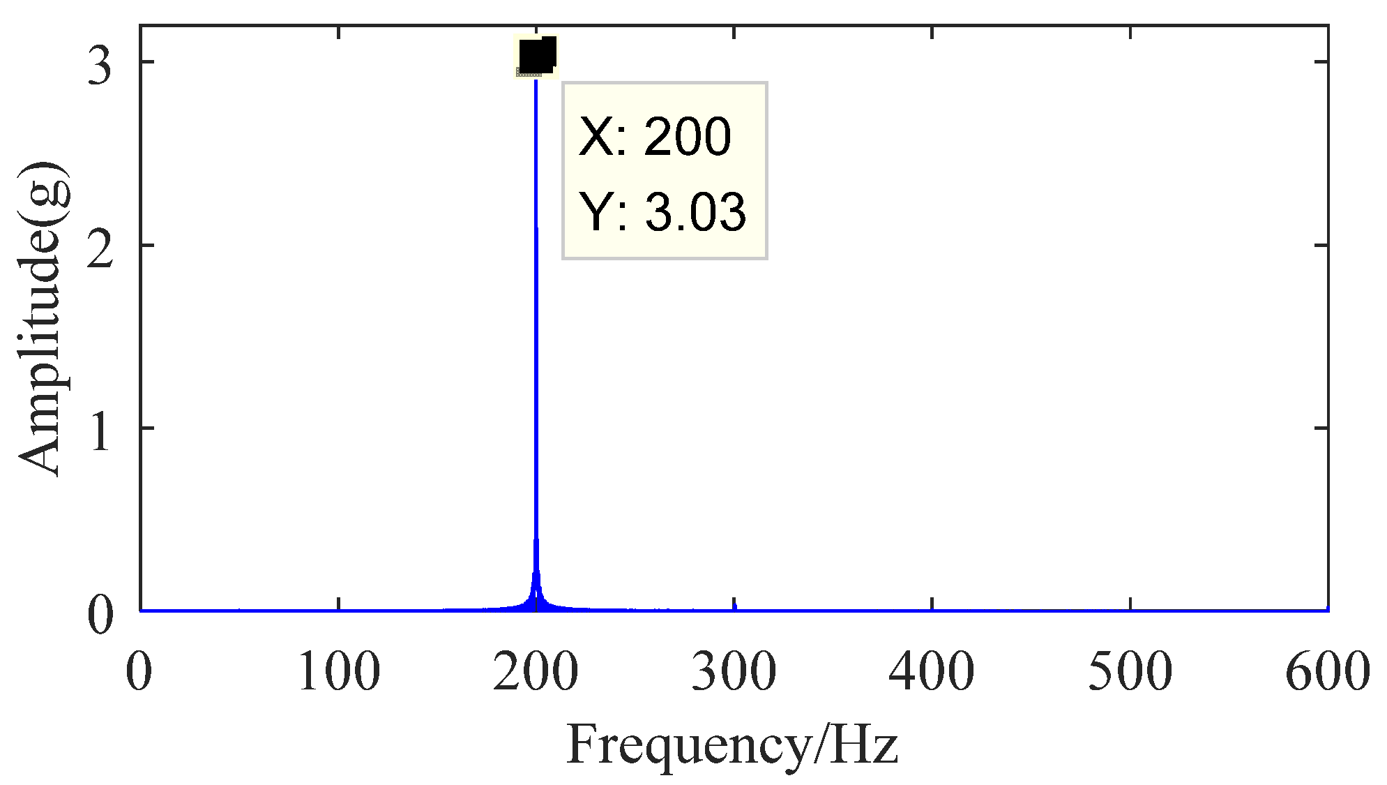
| P11 | 3.030 | 2.905 | 4.13% |
| Test Number | A | B (μm) | C | Damping Rate |
|---|---|---|---|---|
| P1 | 1(8%Y2O3-ZrO2) | 1(100) | 1(Galvanized iron) | 3.33% |
| P2 | 1(8%Y2O3-ZrO2) | 2(150) | 2(304 stainless steel) | 9.97% |
| P3 | 1(8%Y2O3-ZrO2) | 3(200) | 2(304 stainless steel) | 15.78% |
| P4 | 2(Al-Cu-Fe-Cr) | 1(100) | 2(304 stainless steel) | 2.55% |
| P5 | 2(Al-Cu-Fe-Cr) | 2(150) | 2(304 stainless steel) | 9.52% |
| P6 | 2(Al-Cu-Fe-Cr) | 3(200) | 1(Galvanized iron) | 12.06% |
| P7 | 3(ZrO2-PTFE) | 1(100) | 2(304 stainless steel) | 4.21% |
| P8 | 3(ZrO2-PTFE) | 2(150) | 1(Galvanized iron) | 9.93% |
| P9 | 3(ZrO2-PTFE) | 3(200) | 2(304 stainless steel) | 19.93% |
| P10 | 304 stainless steel | |||
| P11 | Galvanized iron | |||
| Sum value K1 | 29.08% | 10.09% | 25.32% | |
| Sum value K2 | 24.13% | 29.42% | 61.96% | |
| Sum value K3 | 34.07% | 47.77% | ||
| Mean K1 | 9.69% | 3.36% | 12.37% | |
| Mean K2 | 8.04% | 9.81% | 13.43% | |
| Mean K3 | 11.36% | 15.92% | ||
| Extremum R | 3.31% | 12.56% | 1.07% | |
| Excellent solution | A3 | B3 | C2 |
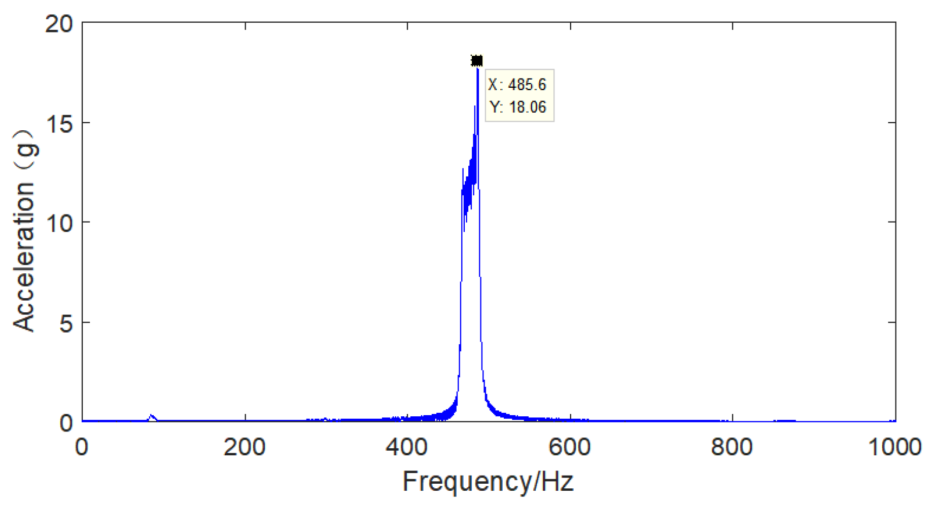
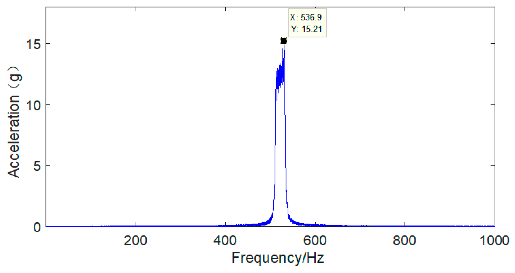
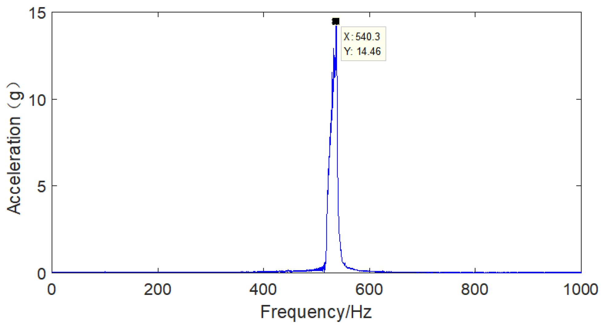
| Test Number | Experimental Vibration Frequency Sweep Acceleration Amplitude (g) | Simulation Vibration Frequency Sweep Acceleration Amplitude (g) | Error Rate |
|---|---|---|---|
| P1 | 18.59 | 17.32 | 6.83% |
| P2 | 16.26 | 15.97 | 1.78% |
| P3 | 15.21 | 14.25 | 6.31% |
| P4 | 17.6 | 16.21 | 7.90% |
| P5 | 16.34 | 15.38 | 5.88% |
| P6 | 16.88 | 15.74 | 6.75% |
| P7 | 17.3 | 15.97 | 7.69% |
| P8 | 17.32 | 16.01 | 7.56% |
| P9 | 14.46 | 13.69 | 5.33% |
| P10 | 18.06 | 17.49 | 3.16% |
| P11 | 19.23 | 18.73 | 2.60% |
Publisher’s Note: MDPI stays neutral with regard to jurisdictional claims in published maps and institutional affiliations. |
© 2022 by the authors. Licensee MDPI, Basel, Switzerland. This article is an open access article distributed under the terms and conditions of the Creative Commons Attribution (CC BY) license (https://creativecommons.org/licenses/by/4.0/).
Share and Cite
Cui, Z.; Liu, J.; Yu, X.; Ran, Z.; Zhang, J.; Zhang, X. Research on the Vibration Characteristics of Aviation Hydraulic Clamp and Pipeline Based on Hard Coating. Coatings 2022, 12, 132. https://doi.org/10.3390/coatings12020132
Cui Z, Liu J, Yu X, Ran Z, Zhang J, Zhang X. Research on the Vibration Characteristics of Aviation Hydraulic Clamp and Pipeline Based on Hard Coating. Coatings. 2022; 12(2):132. https://doi.org/10.3390/coatings12020132
Chicago/Turabian StyleCui, Zhining, Jiaqi Liu, Xiaoguang Yu, Ziqing Ran, Jingbo Zhang, and Xiaolong Zhang. 2022. "Research on the Vibration Characteristics of Aviation Hydraulic Clamp and Pipeline Based on Hard Coating" Coatings 12, no. 2: 132. https://doi.org/10.3390/coatings12020132
APA StyleCui, Z., Liu, J., Yu, X., Ran, Z., Zhang, J., & Zhang, X. (2022). Research on the Vibration Characteristics of Aviation Hydraulic Clamp and Pipeline Based on Hard Coating. Coatings, 12(2), 132. https://doi.org/10.3390/coatings12020132