
Oxidation Protection of High-Temperature Coatings on the Surface of Mo-Based Alloys—A Review


Abstract
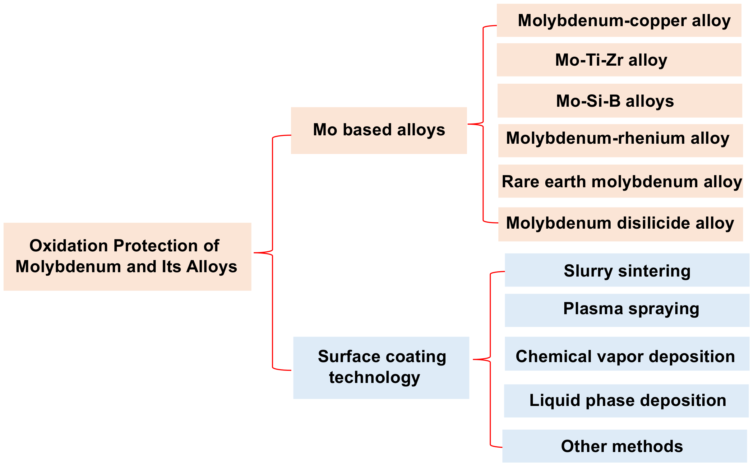
:1. Introduction
2. Microstructure and Oxidation Behavior of Coatings
2.1. Coatings Prepared by Slurry Sintering (SS)
2.1.1. Microstructure and Growth Mechanism of SS Coatings
2.1.2. Oxidation Behavior and Mechanism of SS Coatings
2.2. Coatings Prepared by Plasma-Spraying Technique
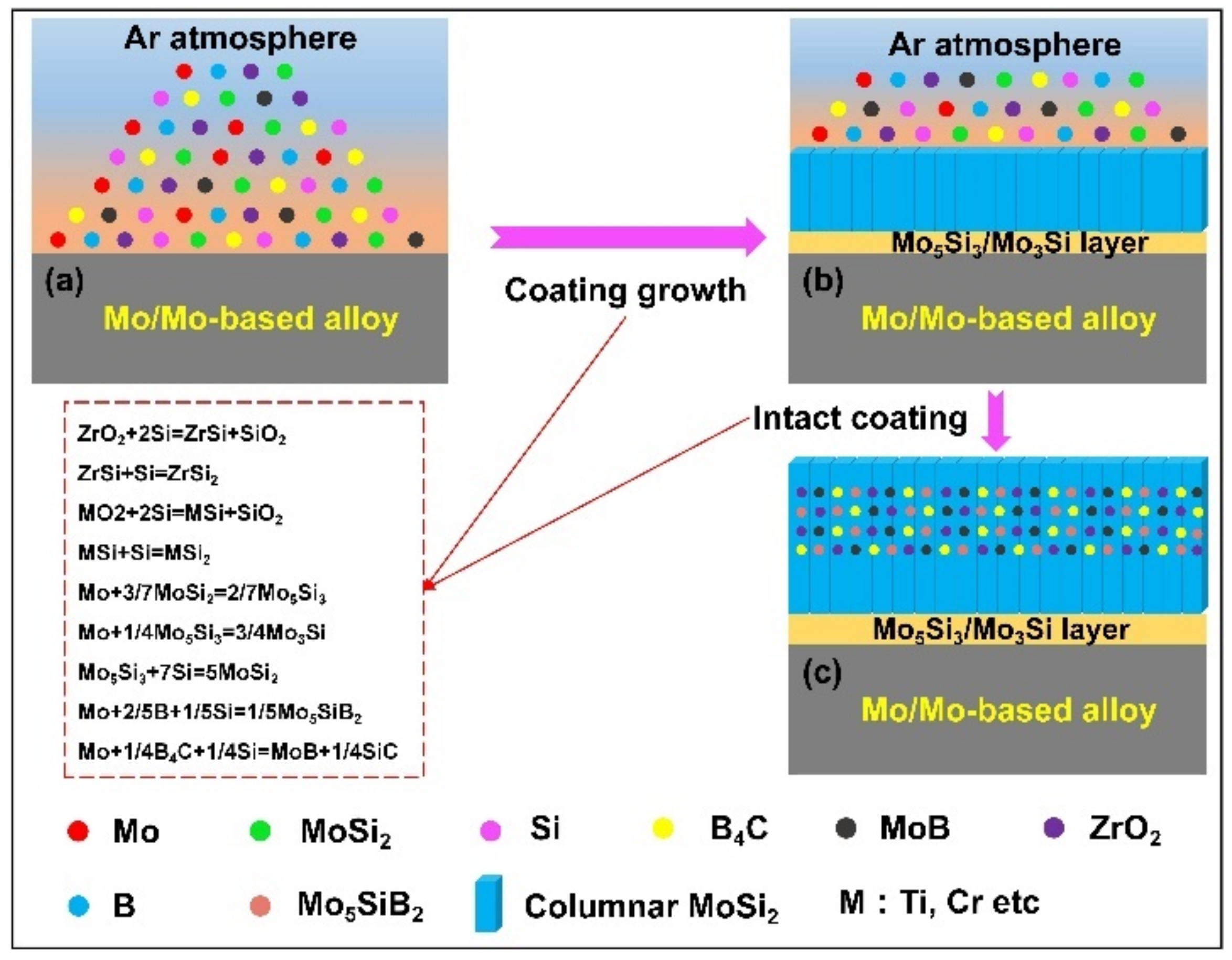
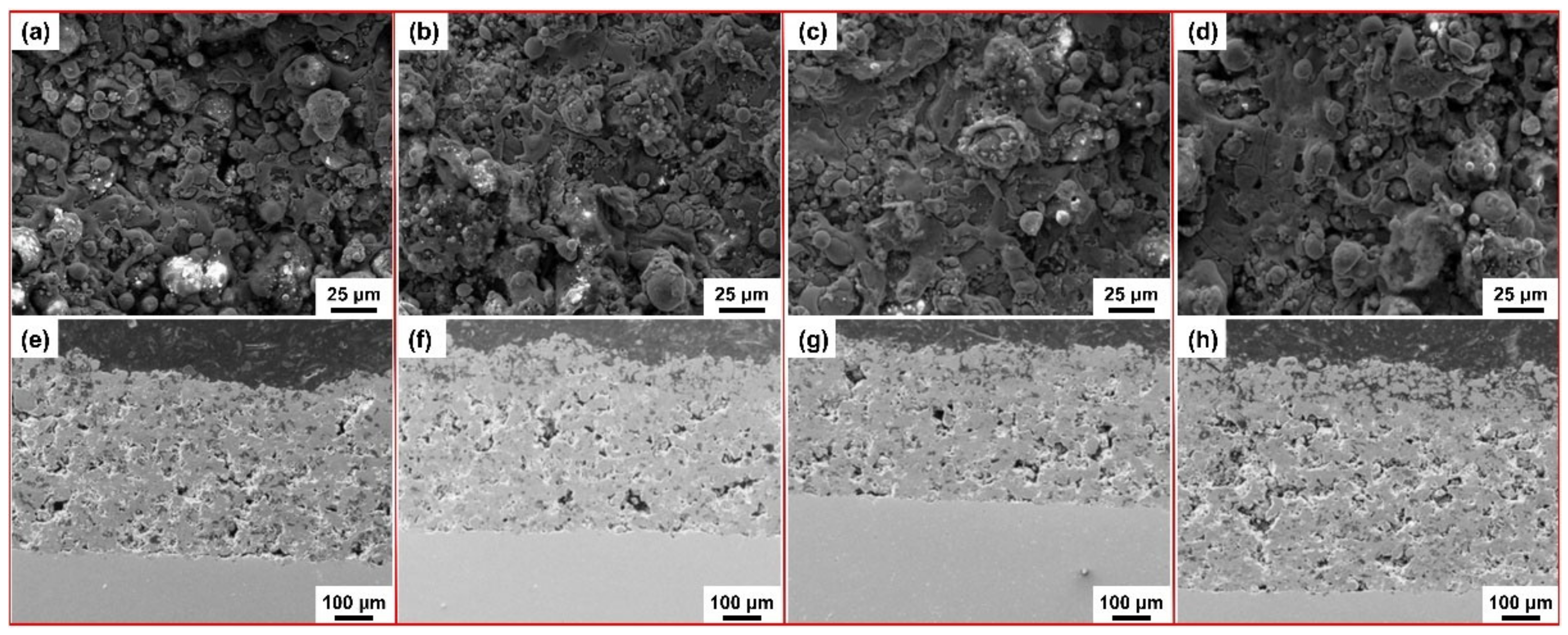
2.2.1. Microstructure and Growth Mechanism of Plasma-Spraying Coatings
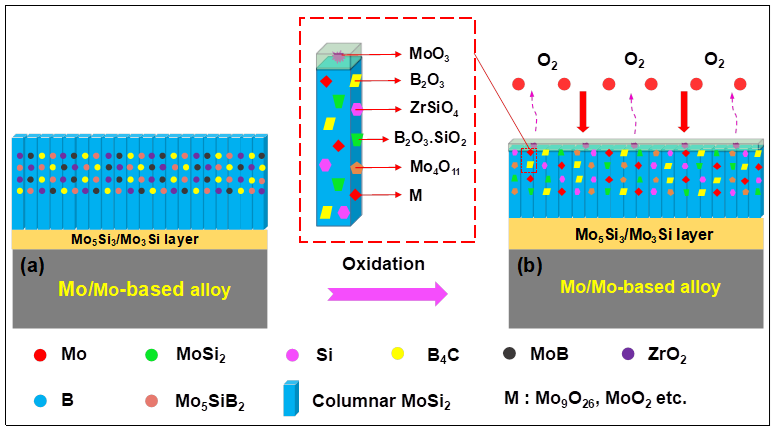
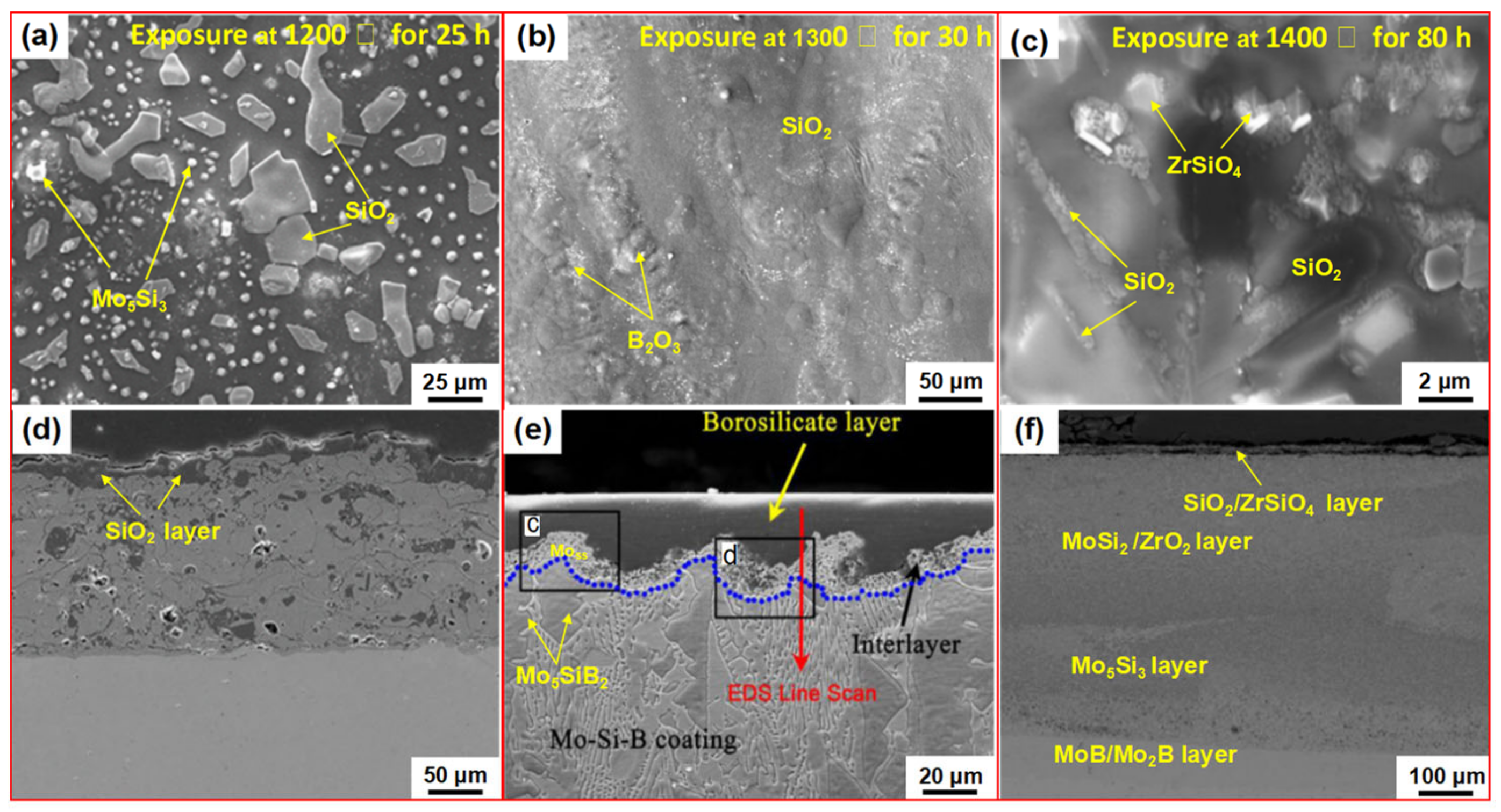
2.2.2. Oxidation Behavior and Mechanism of Plasma-Spraying Coatings
2.3. Coatings Prepared by Chemical Vapor Deposition (CVD) Technology
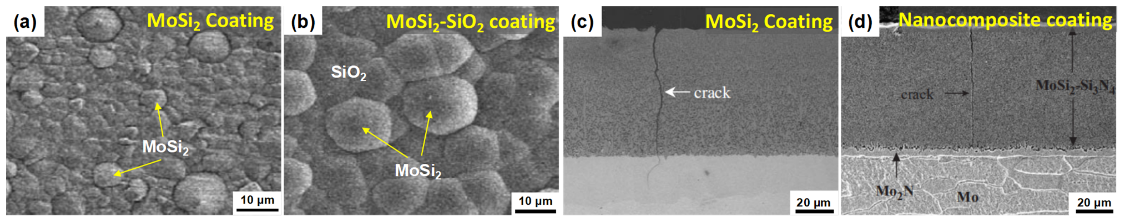
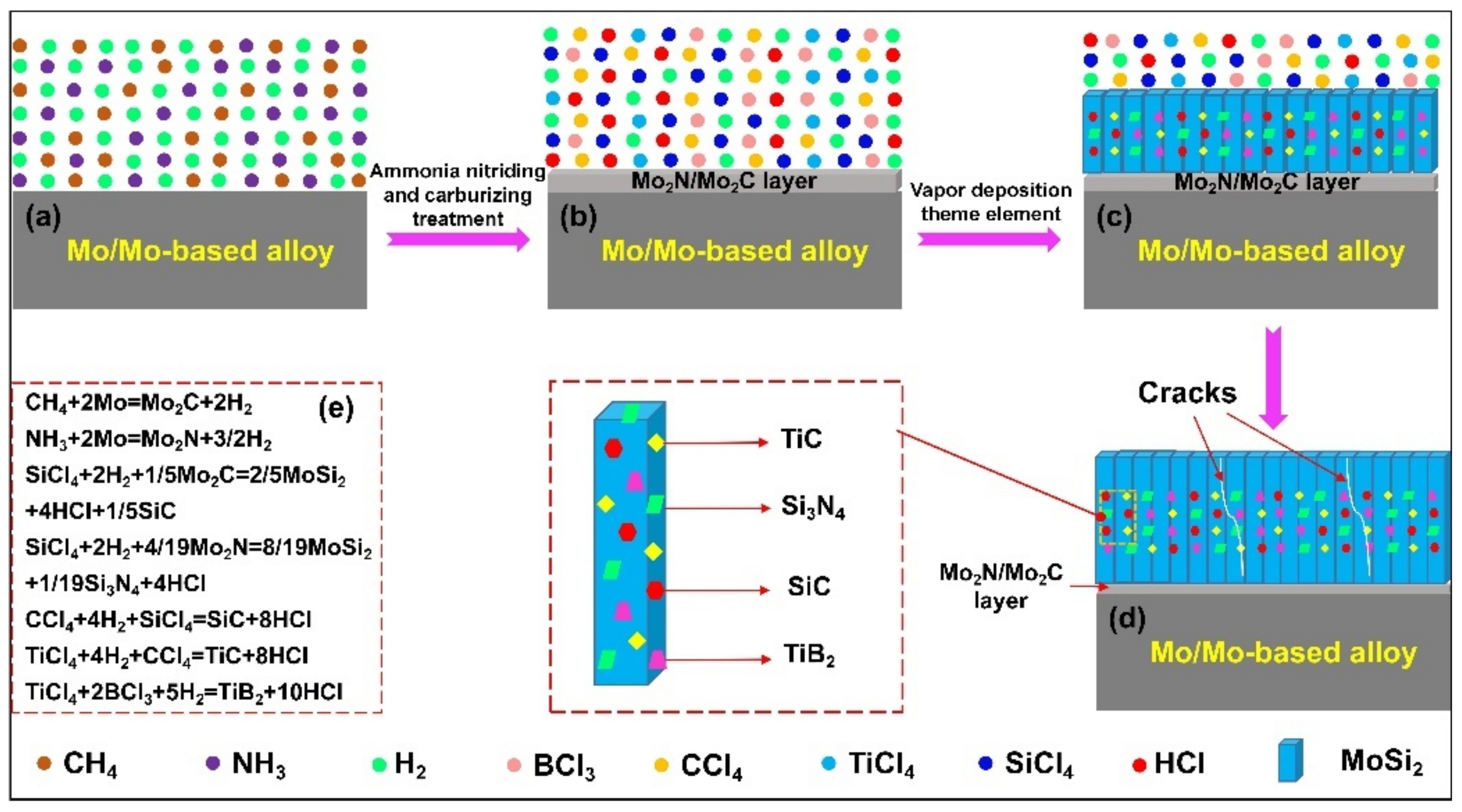
2.3.1. Microstructure and Growth Mechanism of CVD Coatings
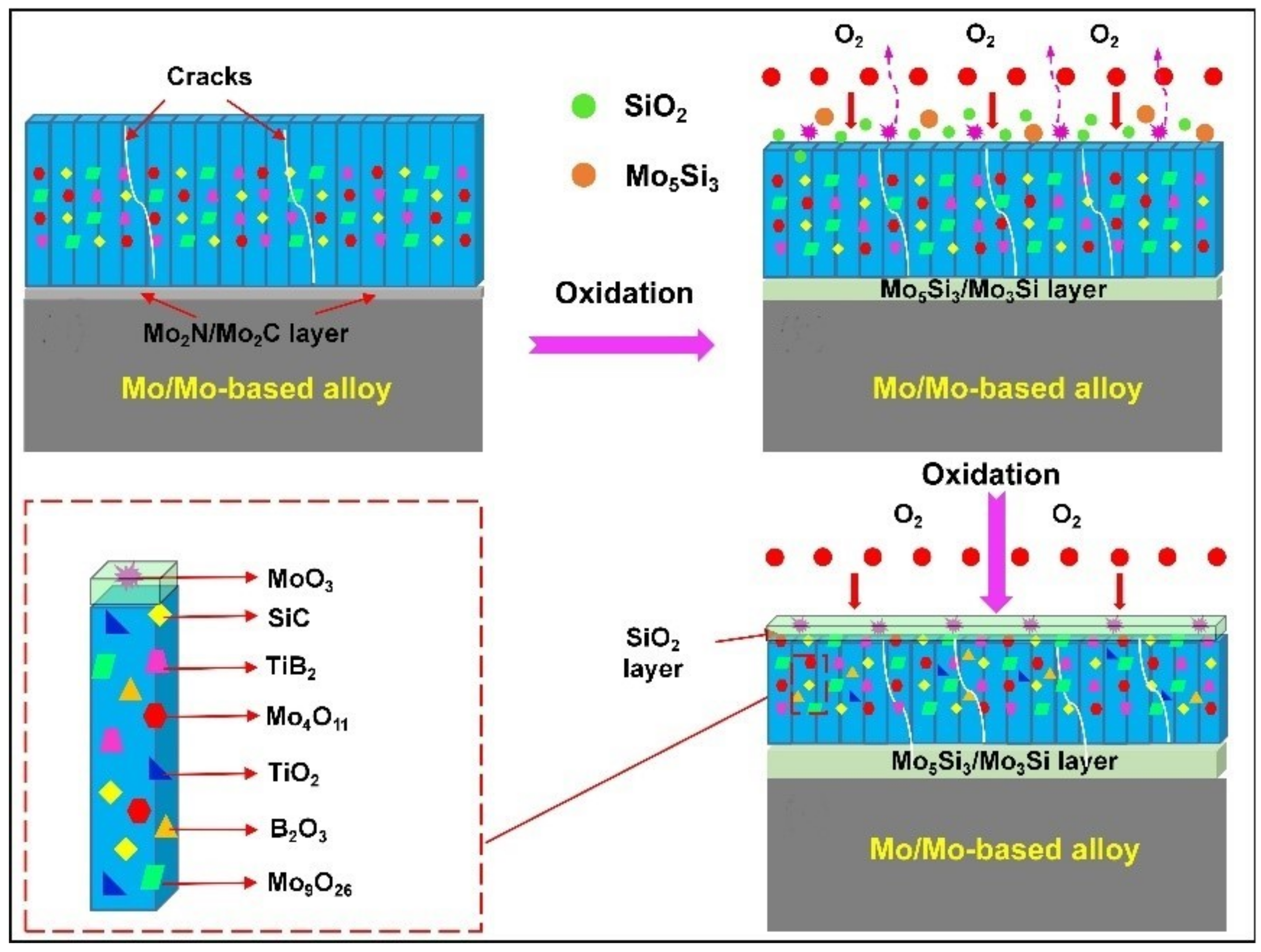
2.3.2. Oxidation Behavior and Mechanism of CVD Coatings
2.4. Coatings Prepared by LiquidPhase Deposition Technology
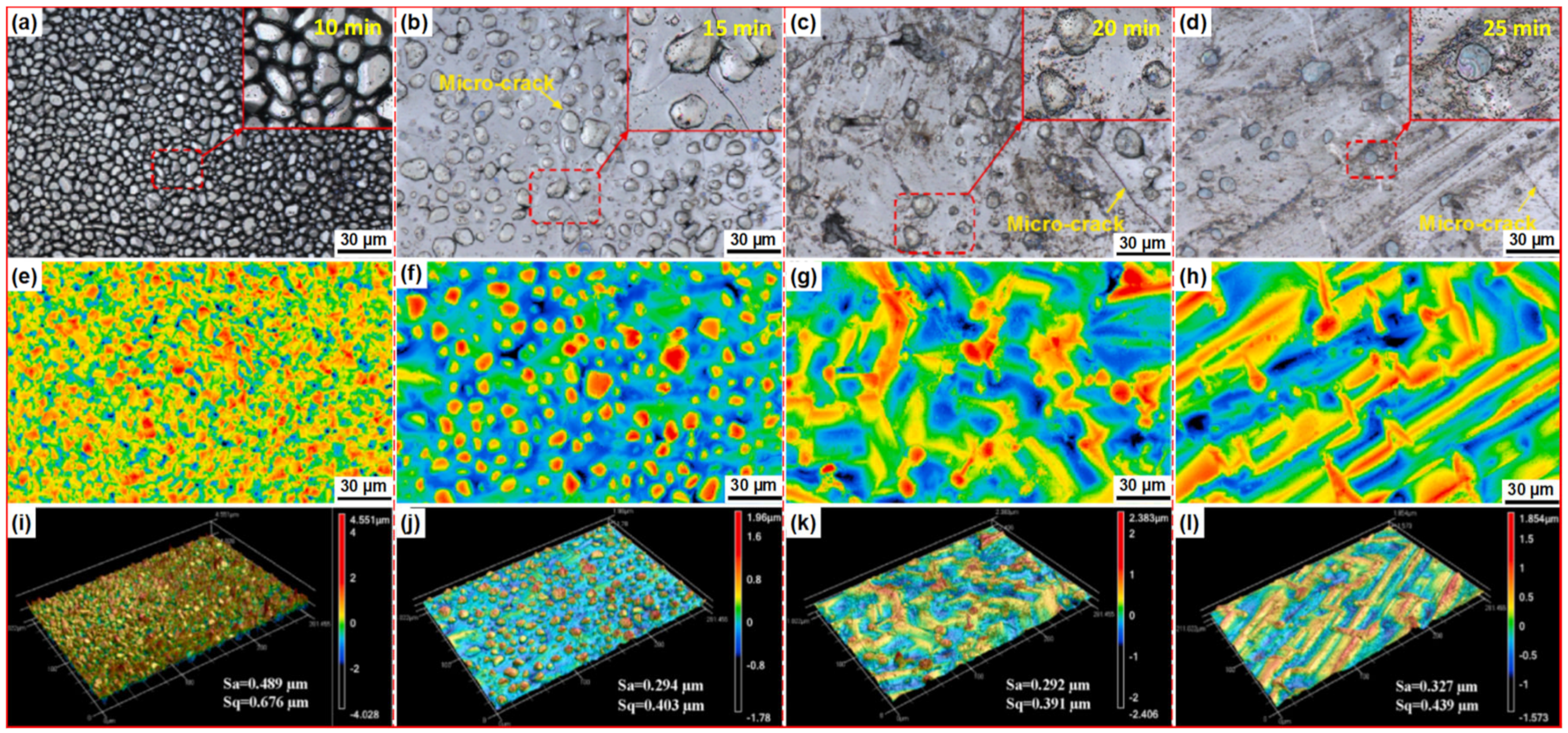
2.4.1. Microstructure and Growth Mechanism of Liquid-Phase Deposition Coatings
2.4.2. Oxidation Behavior and Mechanism of Liquid-Phase Deposition Coatings
3. Conclusions and Prospects
Author Contributions
Funding
Institutional Review Board Statement
Informed Consent Statement
Data Availability Statement
Conflicts of Interest
References
- Chaudhuri, A.; Behera, A.N.; Sarkar, A.; Kapoor, R.; Ray, R.K.; Suwas, S. Hot deformation behaviour of Mo-TZM and understanding the restoration processes involved. Acta Mater. 2019, 164, 153–164. [Google Scholar] [CrossRef]
- Tuzemen, C.; Yavas, B.; Akin, I.; Yucel, O.; Sahin, F.; Goller, G. Production and characterization of TZM based TiC or ZrC reinforced composites prepared by spark plasma sintering (SPS). J. Alloys Compd. 2019, 781, 433–439. [Google Scholar] [CrossRef]
- Pint, B.A. Critical Assessment 4: Challenges in developing high temperature materials. Mater. Sci. Technol. 2013, 30, 1387–1391. [Google Scholar] [CrossRef] [Green Version]
- Majumdar, S.; Kale, G.B.; Sharma, I.G. A study on preparation of Mo–30W alloy by aluminothermic co-reduction of mixed oxides. J. Alloys Compd. 2005, 394, 168–175. [Google Scholar] [CrossRef]
- Xu, J.J.; Yang, T.T.; Yang, Y.; Qian, Y.H.; Li, M.S.; Yin, X.H. Ultra-high temperature oxidation behavior of micro-laminated ZrC/MoSi2 coating on C/C composite. Corros. Sci. 2018, 132, 161–169. [Google Scholar] [CrossRef]
- Khlyustova, A.; Sirotkin, N.; Titov, V.; Agafonov, A. Comparison of two types of plasma in contact with water during the formation of molybdenum oxide. Curr. Appl. Phys. 2020, 20, 1396–1403. [Google Scholar] [CrossRef]
- Kong, H.; Kwon, H.S.; Kim, H.; Jeen, G.S.; Lee, J.; Lee, J.; Heo, Y.S.; Cho, J.; Jeen, H. Reductive-annealing-induced changes in Mo valence states on the surfaces of MoO3 single crystals and their high temperature transport. Curr. Appl. Phys. 2019, 19, 1379–1382. [Google Scholar] [CrossRef]
- Bahamonde, J.P.; Wu, C.Z.; Louie, S.M.; Bao, J.M.; Rodrigues, D.F. Oxidation state of Mo affects dissolution and visible-light photocatalytic activity of MoO3 nanostructures. J. Catal. 2020, 381, 508–519. [Google Scholar] [CrossRef]
- Smolik, G.R.; Petti, D.A.; Schuetz, S.T. Oxidation and volatilization of TZM alloy in air. J. Nucl. Mater. 2000, 283-287, 1458–1462. [Google Scholar] [CrossRef] [Green Version]
- Majumdar, S.; Kapoor, R.; Raveendra, S.; Sinha, H.; Samajdar, I.; Bhargava, P.; Chakravartty, J.K.; Sharma, I.G.; Suri, A.K. A study of hot deformation behavior and microstructural characterization of Mo–TZM alloy. J. Nucl. Mater. 2009, 385, 545–551. [Google Scholar] [CrossRef]
- Amakawa, K.; Wang, Y.Q.; Kröhnert, J.; Schlögl, R.; Trunschke, A. Acid sites on silica-supported molybdenum oxides probed by ammonia adsorption: Experiment and theory. Mol. Catal. 2019, 478, 110–580. [Google Scholar] [CrossRef]
- Mannheim, R.L.; Garin, J.L. Structural identification of phases in Mo–Re alloys within the range from 5 to 95% Re. J. Mater. Process. Technol. 2003, 143-144, 533–538. [Google Scholar] [CrossRef]
- Cui, K.K.; Zhang, Y.Y.; Fu, T.; Hussain, S.; Algarni, T.S.; Wang, J.; Zhang, X.; Ali, S. Effects of Cr2O3 Content on Microstructure and Mechanical Properties of Al2O3 Matrix Composites. Coatings 2021, 11, 234. [Google Scholar] [CrossRef]
- Cui, Y.C.; Derby, B.; Li, N.; Misra, A. Fracture resistance of hierarchical Cu–Mo nanocomposite thin films. Mater. Sci. Eng. A 2021, 799, 139–891. [Google Scholar] [CrossRef]
- Pan, Y.; Zhang, J. Influence of noble metals on the electronic and optical properties of the monoclinic ZrO2: A first-principles study. Vacuum 2021, 187, 110112. [Google Scholar] [CrossRef]
- Li, J.C.; Wei, L.L.; He, J.; Chen, H. The role of Re in improving the oxidation-resistance of a Re modified PtAl coating on Mo-rich single crystal superalloy. J. Mater. Sci. Technol. 2020, 58, 63–72. [Google Scholar] [CrossRef]
- Paul, B.; Kishor, J.; Majumdar, S.; Kain, V. Studies on growth mechanism of intermediate layer of (Mo,W)5Si3 and interdiffusion in the (Mo,W)-(Mo,W)Si2 system prepared by pack cementation coating. Surf. Interfaces 2020, 18, 100–458. [Google Scholar] [CrossRef]
- Pan, Y. The structural, mechanical and thermodynamic properties of the orthorhombic TMAl (TM=Ti, Y, Zr and Hf) aluminides from first-principles calculations. Vacuum 2020, 181, 109742. [Google Scholar] [CrossRef]
- Lu, Y.; Watanabe, M.; Miyata, R.; Nakamura, J.; Yamada, J.; Kato, H.; Yoshimi, K. Microstructures and mechanical properties of TiC-particulate-reinforced Ti–Mo–Al intermetallic matrix composites. Mater. Sci. Eng. A 2020, 790, 139–523. [Google Scholar] [CrossRef]
- Cui, K.K.; Fu, T.; Zhang, Y.Y.; Wang, J.; Mao, H.B.; Tan, T.B. Microstructure and mechanical properties of CaAl12O19 reinforced Al2O3-Cr2O3 composites. J. Eur. Ceram. Soc. 2021, 41, 7935–7945. [Google Scholar] [CrossRef]
- Niu, F.X.; Wang, Y.X.; Wang, Y.Y.; Ma, L.R.; Liu, J.J.; Wang, C.G. A crack-free SiC nanowire-toughened Si-Mo-W-C coating prepared on graphite materials for enhancing the oxidation resistance. Surf. Coat. Technol. 2018, 344, 52–57. [Google Scholar] [CrossRef]
- Zhang, Y.Y.; Fu, T.; Cui, K.K.; Shen, F.Q.; Wang, J.; Yu, L.H.; Mao, H.B. Evolution of surface morphology, roughness and texture of tungsten disilicide coatings on tungsten substrate. Vacuum 2021, 191, 110297. [Google Scholar] [CrossRef]
- Jiang, C.; Mariani, R.D.; Adkins, C.A. Ab initio investigation and thermodynamic modeling of the Mo–Ti–Zr system. Materialia 2020, 10, 100–701. [Google Scholar] [CrossRef]
- Zhao, M.; Xu, B.Y.; Shao, Y.M.; Zhu, Y.; Wu, J.; Wu, S.S.; Yan, Y.W. Microstructure and oxidation mechanism of multiphase Mo–Ti–Si–B alloys at 800 °C. Corros. Sci. 2021, 187, 109518. [Google Scholar] [CrossRef]
- Huang, L.; Pan, Y.F.; Zhang, J.X.; Du, Y.; Luo, F.H.; Zhang, S.Y. CALPHAD-type modeling of the C–Hf–Mo system over the whole composition and temperature ranges. Thermochim. Acta 2020, 692, 178–716. [Google Scholar] [CrossRef]
- Fu, T.; Cui, K.K.; Zhang, Y.Y.; Wang, J.; Zhang, X.; Shen, F.Q.; Yu, L.H.; Mao, H.B. Microstructure and Oxidation Behavior of Anti-Oxidation Coatings on Mo-Based Alloys through HAPC Process: A Review. Coatings 2021, 11, 883. [Google Scholar] [CrossRef]
- Hu, P.; Zhou, Y.H.; Chang, T.; Yua, Z.T.; Wang, K.S.; Yang, F.; Hua, B.L.; Cao, W.C.; Yu, H.L. Investigation on compression behavior of TZM and La2O3 doped TZM Alloys at high temperature. Mater. Sci. Eng. A 2017, 687, 276–280. [Google Scholar] [CrossRef]
- Lange, A.; Braun, R.; Heilmaier, M. Oxidation behavior of magnetron sputtered double layer coatings containing molybdenum, silicon and boron. Intermetallics 2014, 48, 19–27. [Google Scholar] [CrossRef]
- Suzuki, R.O.; Ishikawa, M.; Ono, K. MoSi2 coating on molybdenum using molten salt. J. Alloys Compd. 2000, 306, 285–291. [Google Scholar] [CrossRef]
- Kuznetsov, S.A.; Kuznetsova, S.V.; Rebrov, E.V.; Mies, M.J.M.; de Croon, M.H.J.M.; Schouten, J.C. Synthesis of molybdenum borides and molybdenum silicides in molten salts and their oxidation behavior in an air–water mixture. Surf. Coat. Technol. 2005, 195, 182–188. [Google Scholar] [CrossRef]
- Anton, R.; Laska, N.; Schulz, U.; Obert, S.; Heilmaier, M. Magnetron Sputtered Silicon Coatings as Oxidation Protection for Mo-Based Alloys. Adv. Eng. Mater. 2020, 22, 7. [Google Scholar] [CrossRef]
- Mao, H.; Shen, F.; Zhang, Y.; Wang, J.; Cui, K.; Wang, H.; Lv, T.; Fu, T.; Tan, T. Microstructure and Mechanical Properties of Carbide Reinforced TiC-Based Ultra-High Temperature Ceramics: A Review. Coatings 2021, 11, 1444. [Google Scholar] [CrossRef]
- Huang, C.; Zhang, Y.Z.; Vilar, R. Microstructure and anti-oxidation behavior of laser clad Ni–20Cr coating on molybdenum surface. Surf. Coat. Technol. 2010, 205, 835–840. [Google Scholar] [CrossRef]
- Zhang, H.A.; Lv, J.X.; Wu, Y.H.; Gu, S.Y.; Huang, Y.; Chen, Y. Oxidation behavior of (Mo,W)Si2–Si3N4 composite coating on molybdenum substrate at 1600 °C. Ceram. Int. 2015, 41, 14890–14895. [Google Scholar] [CrossRef]
- Yoon, J.K.; Lee, J.K.; Byun, J.Y.; Kim, G.H.; Paik, Y.H.; Kim, J.S. Effect of ammonia nitridation on the microstructure of MoSi2 coatings formed by chemical vapor deposition of Si on Mo substrates. Surf. Coat. Technol. 2002, 160, 29–37. [Google Scholar] [CrossRef]
- Pu, R.; Sun, Y.A.; Xu, J.W.; Zhou, X.J.; Li, S.; Zhang, B.; Cai, Z.Y.; Liu, S.N.; Zhao, X.J.; Xiao, L.R. Microstructure and properties of Mo-based double-layer MoSi2 thick coating by a new two-step method. Surf. Coat. Technol. 2020, 394, 125840. [Google Scholar] [CrossRef]
- Zhang, Y.Y.; Yu, L.H.; Fu, T.; Wang, J.; Shen, F.Q.; Cui, K.K. Microstructure evolution and growth mechanism of Si-MoSi2 composite coatings on TZM (Mo-0.5Ti-0.1Zr-0.02 C) alloy. J. Alloys Compd. 2021, 894, 162403. [Google Scholar] [CrossRef]
- Fu, T.; Cui, K.K.; Zhang, Y.Y.; Wang, J.; Shen, F.Q.; Yu, L.H.; Qie, J.M.; Zhang, X. Oxidation protection of tungsten alloys for nuclear fusion applications: A comprehensive review. J. Alloys Compd. 2021, 884, 161057. [Google Scholar] [CrossRef]
- Pint, B.A. Invited Review Paper in Commemoration of Over 50 Years of Oxidation of Metals: Addressing the Role of Water Vapor on Long-Term Stainless Steel Oxidation Behavior. Oxid. Met. 2021, 95, 335–357. [Google Scholar] [CrossRef]
- Cui, K.K.; Zhang, Y.Y.; Fu, T.; Wang, J.; Zhang, X. Toughening Mechanism of Mullite Matrix Composites: A Review. Coatings 2020, 10, 672. [Google Scholar] [CrossRef]
- Zheng, X.Q.; Liu, Y. Slurry erosion–corrosion wear behavior in SiC-containing NaOH solutions of Mo2NiB2 cermets prepared by reactive sintering. Int. J. Refract. Met. Hard Mater. 2019, 78, 193–200. [Google Scholar] [CrossRef]
- Gao, J.S.; Liu, Z.M.; Yan, Z.Q.; He, Y. A novel slurry blending method for a uniform dispersion of carbon nanotubes in natural rubber composites. Results Phys. 2019, 15, 102–720. [Google Scholar] [CrossRef]
- Li, W.; Fan, J.L.; Fan, Y.; Xiao, L.R.; Cheng, H.C. MoSi2/(Mo, Ti)Si2 dual-phase composite coating for oxidation protection of molybdenum alloy. J. Alloys Compd. 2018, 740, 711–718. [Google Scholar] [CrossRef]
- Cai, Z.Y.; Liu, S.N.; Xiao, L.R.; Fang, Z.; Li, W.; Zhang, B. Oxidation behavior and microstructural evolution of a slurry sintered Si-Mo coating on Mo alloy at 1650 °C. Surf. Coat. Technol. 2017, 324, 182–189. [Google Scholar] [CrossRef]
- Chakraborty, S.P. Development of Protective Coating of MoSi2 over TZM Alloy Substrate by Slurry Coating Technique. Mater. Today Proc. 2016, 3, 3071–3076. [Google Scholar] [CrossRef]
- Cai, Z.Y.; Wu, Y.H.; Liu, H.Y.; Tian, G.Y.; Pu, R.; Piao, S.M.; Tang, X.Y.; Liu, S.N.; Zhao, X.J.; Xiao, L.R. Formation and oxidation resistance of a new YSZ modified silicide coating on Mo-based alloy. Mater. Des. 2018, 155, 463–474. [Google Scholar] [CrossRef]
- Alam, M.Z.; Venkataraman, B.; Sarma, B.; Das, D.K. MoSi2 coating on Mo substrate for short-term oxidation protection in air. J. Alloys Compd. 2009, 487, 335–340. [Google Scholar] [CrossRef]
- Farje, J.A.V.; Matsunoshita, H.; Kishida, K.; Inui, H. Microstructure and mechanical properties of a MoSi2-Mo5Si3 eutectic composite processed by laser surface melting. Mater. Charact. 2019, 148, 162–170. [Google Scholar] [CrossRef]
- Yang, T.; Guo, X.P. Oxidation behavior of Zr-Y alloyed Mo-Si-B based alloys. Int. J. Refract. Met. Hard Mater. 2020, 88, 105–200. [Google Scholar] [CrossRef]
- Alam, M.S.; Shafirovich, E. ShafirovichE. Mechanically activated combustion synthesis of molybdenum silicides and borosilicides for ultrahigh-temperature structural applications. Proc. Combust. Inst. 2015, 35, 2275–2281. [Google Scholar] [CrossRef]
- Goodfellow, A.J.; Galindo-Nava, E.I.; Christofidou, K.A.; Jones, N.G.; Boyer, C.D.; Martin, T.L.; Bagot, P.A.J.; Hardy, M.C.; Stone, H.J. The effect of phase chemistry on the extent of strengthening mechanisms in model Ni-Cr-Al-Ti-Mo based superalloys. Acta Mater. 2018, 153, 290–302. [Google Scholar] [CrossRef]
- Pint, B.A.; Unocic, K.A. Steam Oxidation Evaluation of Fe–Cr Alloys for Accident Tolerant Nuclear Fuel Cladding. Oxid. Met. 2017, 87, 515–526. [Google Scholar] [CrossRef]
- Müller, F.; Gorr, B.; Christ, H.J.; Chen, H.; Kauffmann, A.; Laube, S.; Heilmaier, M. Formation of complex intermetallic phases in novel refractory high-entropy alloys NbMoCrTiAl and TaMoCrTiAl: Thermodynamic assessment and experimental validation. J. Alloys Compd. 2020, 842, 2515–5726. [Google Scholar] [CrossRef]
- Vaunois, J.R.; Poulain, M.; Kanouté, P.; Chaboche, J.L. Development of bending tests for near shear mode interfacial toughness measurement of EB-PVD thermal barrier coatings. Eng. Fract. Mech. 2017, 171, 110–134. [Google Scholar] [CrossRef]
- Gupta, M.; Li, X.H.; Markocsan, N.; Kjellman, B. Design of high lifetime suspension plasma sprayed thermal barrier coatings. J. Eur. Ceram. Soc. 2020, 40, 768–779. [Google Scholar] [CrossRef]
- Gorr, S.M.B.; Christ, H.J.; Schliephake, D.; Heilmaier, M. Oxidation mechanisms of lanthanum-alloyed Mo–Si–B. Corros. Sci. 2014, 88, 360–371. [Google Scholar] [CrossRef]
- Wang, Y.; Wang, D.Z.; Yan, J.H.; Sun, A.K. Preparation and characterization of molybdenum disilicide coating on molybdenum substrate by air plasma spraying. Appl. Surf. Sci. 2013, 284, 881–888. [Google Scholar] [CrossRef]
- Deng, X.K.; Zhang, G.J.; Wang, T.; Ren, S.; Shi, Y.; Bai, Z.L.; Cao, Q. Microstructure and oxidation resistance of a multiphase Mo-Si-B ceramic coating on Mo substrates deposited by a plasma transferred arc process. Ceram. Int. 2019, 45, 415–423. [Google Scholar] [CrossRef]
- Zhu, L.; Zhu, Y.S.; Ren, X.R.; Zhang, P.; Qiao, J.H.; Feng, P.Z. Microstructure, properties and oxidation behavior of MoSi2-MoB-ZrO2 coating for Mo substrate using spark plasma sintering. Surf. Coat. Technol. 2019, 375, 773–781. [Google Scholar] [CrossRef]
- Chakraborty, S.P. Studies on the development of TZM alloy by aluminothermic coreduction process and formation of protective coating over the alloy by plasma spray technique. Int. J. Refract. Met. Hard Mater. 2011, 29, 5623–5630. [Google Scholar] [CrossRef]
- Yavas, B.; Goller, G. A novel approach to boriding of TZM by spark plasma sintering method. Int. J. Refract. Met. Hard Mater. 2019, 78, 273–281. [Google Scholar] [CrossRef]
- Shao, F.; Zhao, H.Y.; Liu, C.G.; Zhong, X.H.; Zhuang, Y.; Ni, J.X.; Tao, S.Y. Dense yttria-stabilized zirconia coatings fabricated by plasma spray-physical vapor deposition. Ceram. Int. 2017, 43, 2305–2313. [Google Scholar] [CrossRef]
- Gao, L.H.; Guo, H.B.; Wei, L.L.; Li, C.Y.; Gong, S.K.; Xu, H.B. Microstructure and mechanical properties of yttria stabilized zirconia coatings prepared by plasma spray physical vapor deposition. Ceram. Int. 2015, 41, 8305–8311. [Google Scholar] [CrossRef]
- Ganvir, A.; Calinas, R.F.; Markocsan, N.; Curry, N.; Joshi, S. Experimental visualization of microstructure evolution during suspension plasma spraying of thermal barrier coatings. J. Eur. Ceram. Soc. 2019, 39, 470–481. [Google Scholar] [CrossRef]
- Ganvir, A.; Curry, N.; Markocsan, N.; Nylén, P.; Toma, F.L. Comparative study of suspension plasma sprayed and suspension high velocity oxy-fuel sprayed YSZ thermal barrier coatings. Surf. Coat. Technol. 2015, 268, 70–76. [Google Scholar] [CrossRef]
- Yavas, B.; Goller, G. Investigation the effect of B 4 C addition on properties of TZM alloy prepared by spark plasma sintering. Int. J. Refract. Met. Hard Mater. 2016, 58, 182–188. [Google Scholar] [CrossRef]
- Zhao, Y.L.; Wen, J.H.; Wen, J.H.; Peyraut, F.; Planche, M.P.; Misra, S.; Lenoir, B.; Ilavsky, J.; Liao, H.L.; Montavon, G. Porous architecture and thermal properties of thermal barrier coatings deposited by suspension plasma spray. Surf. Coat. Technol. 2020, 386, 125462. [Google Scholar] [CrossRef]
- Gizynski, M.; Chen, X.; Dusautoy, N.; Araki, H.; Kuroda, S.; Watanabe, M.; Pakiela, Z. Comparative study of the failure mechanism of atmospheric and suspension plasma sprayed thermal barrier coatings. Surf. Coat. Technol. 2019, 370, 163–176. [Google Scholar] [CrossRef]
- Zhang, Y.; Pint, B.A.; Cooley, K.M.; Haynes, J.A. Effect of nitrogen on the formation and oxidation behavior of iron aluminide coatings. Surf. Coatings Technol. 2005, 200, 1231–1235. [Google Scholar] [CrossRef]
- Pochet, L.F.; Howard, P.; Safaie, S. Practical aspects of deposition of CVD SiC and boron silicon carbide onto high temperature composites. Surf. Coat. Technol. 1996, 86-87, 135–141. [Google Scholar] [CrossRef]
- Nyutu, E.K.; Kmetz, M.A.; Suib, S.L. Formation of MoSi2–SiO2 coatings on molybdenum substrates by CVD/MOCVD. Surf. Coat. Technol. 2006, 200, 3980–3986. [Google Scholar] [CrossRef]
- Yoon, J.K.; Kim, G.H.; Han, J.H.; Shon, I.J.; Doh, J.M.; Hong, K.T. Low-temperature cyclic oxidation behavior of MoSi2/Si3N4 nanocomposite coating formed on Mo substrate at 773 K. Surf. Coat. Technol. 2005, 200, 2537–2546. [Google Scholar] [CrossRef]
- Huang, X.X.; Sun, S.C.; Lu, S.D.; Li, K.H.; Tu, G.F.; Song, J.X. Synthesis and characterization of oxidation-resistant TiB2 coating on molybdenum substrate by chemical vapor deposition. Mater. Lett. 2018, 228, 53–56. [Google Scholar] [CrossRef]
- Du, J.H.; Li, Z.X.; Liu, G.J.; Zhou, H.; Huang, C.L. Surface characterization of CVD tungsten coating on molybdenum substrate. Surf. Coat. Technol. 2005, 198, 169–172. [Google Scholar] [CrossRef]
- Yoon, J.K.; Lee, K.H.; Kim, G.H.; Han, J.H.; Doh, J.M.; Hong, K.T. Low-Temperature Cyclic Oxidation Behavior of MoSi2/SiC Nanocomposite Coating Formed on Mo Substrate. Mater. Trans. 2004, 45, 2435–2442. [Google Scholar] [CrossRef] [Green Version]
- Céspedes, E.; Wirz, M.; Sánchez-García, J.A.; Fraga, L.A.; Galindo, R.E.; Prietoa, C. Novel Mo–Si3N4 based selective coating for high temperature concentrating solar power applications. Sol. Energy Mater. Sol. Cells 2014, 122, 217–225. [Google Scholar] [CrossRef]
- Jung, Y.I.; Kim, S.H.; Kim, H.G.; Park, J.Y.; Kim, W.J. Microstructures of diffusion bonded SiC ceramics using Ti and Mo interlayers. J. Nucl. Mater. 2013, 441, 510–513. [Google Scholar] [CrossRef]
- Huang, X.X.; Sun, S.C.; Tu, G.F. Investigation of mechanical properties and oxidation resistance of CVD TiB2 ceramic coating on molybdenum. J. Mater. Res. Technol. 2020, 9, 282–290. [Google Scholar] [CrossRef]
- Anton, R.; Hüning, S.; Laska, N.; Weber, M.; Schellert, S.; Gorr, B.; Christ, H.J.; Schulz, U. Graded PVD Mo-Si interlayer between Si coating and Mo-Si-B alloys: Investigation of oxidation behaviour. Corros. Sci. 2021, 192, 109–843. [Google Scholar] [CrossRef]
- Lange, A.; Braun, R.; Schulz, U. PVD thermal barrier coating systems for M-Si-B alloys. Mater. High. Temp. 2017, 35, 195–203. [Google Scholar] [CrossRef]
- Krüger, M.; Franz, S.; Saage, H.; Heilmaier, M.; Schneibel, J.H.; J´ehanno, P.; B¨oning, M.; Kestler, H. Mechanically alloyed Mo–Si–B alloys with a continuous α-Mo matrix and improved mechanical properties. Intermetallics 2008, 16, 933–941. [Google Scholar] [CrossRef]
- Zhang, Y.Y.; Hussain, S.; Cui, K.K.; Fu, T.; Wang, J.; Javed, M.S.; Lv, Y.; Aslam, B. Microstructure and Mechanical Properties of MoSi2 Coating Deposited on Mo Substrate by Hot Dipping Processes. J. Nanoelectron. Optoelectron. 2019, 14, 1680–1685. [Google Scholar] [CrossRef]
- Zhang, Y.Y.; Cui, K.K.; Fu, T.; Wang, J.; Qie, J.M.; Zhang, X. Synthesis WSi2 coating on W substrate by HDS method with various deposition times. Appl. Surf. Sci. 2020, 511, 145551. [Google Scholar] [CrossRef]
- Zhang, Y.Y.; Qie, J.M.; Cui, K.K.; Fu, T.; Fan, X.L.; Wang, J.; Zhang, X. Effect of hot dip silicon-plating temperature on microstructure characteristics of silicide coating on tungsten substrate. Ceram. Int. 2020, 46, 5223–5228. [Google Scholar] [CrossRef]
- Zhang, Y.Y.; Li, Y.G.; Bai, C.G. Microstructure and oxidation behavior of Si–MoSi2 functionally graded coating on Mo substrate. Ceram. Int. 2017, 43, 6250–6256. [Google Scholar] [CrossRef]
- Zhang, Y.Y.; Li, Y.G.; Qi, Y.H.; Zou, Z.S. The Characters of Mo-MoSi2 Functionally Graded Coating. High Temp. Mater. Process. 2014, 33, 239–244. [Google Scholar] [CrossRef]
- Zhang, Y.Y.; Zhao, J.; Li, J.H.; Lei, J. Effect of hot-dip siliconizing time on phase composition and microstructure of Mo–MoSi2 high temperature structural materials. Ceram. Int. 2019, 45, 5588–5593. [Google Scholar] [CrossRef]
- Wang, S.P.; Zhou, L.; Li, C.J.; Li, Z.X.; Li, H.Z.; Yang, L.J. Morphology of composite coatings formed on Mo1 substrate using hot-dip aluminising and micro-arc oxidation techniques. Appl. Surf. Sci. 2020, 508, 144–761. [Google Scholar] [CrossRef]
- Zhang, Y.Y.; Cui, K.K.; Gao, Q.J.; Hussain, S.; Lv, Y. Investigation of morphology and texture properties of WSi2 coatings on W substrate based on contact-mode AFM and EBSD. Surf. Coat. Technol. 2020, 396, 125966. [Google Scholar] [CrossRef]
- Zhang, Y.Y.; Yu, L.H.; Fu, T.; Wang, J.; Shen, F.Q.; Cui, K.K.; Wang, H. Microstructure and oxidation resistance of Si-MoSi2 ceramic coating on TZM (Mo-0.5Ti-0.1Zr-0.02C) alloy at 1500 °C. Surf. Coat. Technol. 2021, 431, 128037. [Google Scholar] [CrossRef]
- Zhang, Y.Y.; Cui, K.K.; Fu, T.; Wang, J.; Shen, F.Q.; Zhang, X.; Yu, L.H. Formation of MoSi2 and Si/MoSi2 coatings on TZM (Mo–0.5Ti–0.1Zr–0.02C) alloy by hot dip silicon-plating method. Ceram. Int. 2021, 47, 23053–23065. [Google Scholar] [CrossRef]


| Substrate | Slurry Composition and Particle Size | Process Conditions | Coating Composition and Thickness (µm) | Bond Strength (MPa) | Surface Hardness (GPa) | Grain Size (µm) | Refs. | |||
|---|---|---|---|---|---|---|---|---|---|---|
| Composition (wt%) | Particle Size (µm) | Atmosphere | Treatment Time and Temperature | Outer Layer | Interface Layer | |||||
| TZM | 75Si-10Mo-15Ti CN, EAC | 1.00–3.00 | Vacuum | 1450 °C, 15.00 min | MoSi2-(Mo,Ti) Si2 (120.00) | (Mo,Ti)5Si3 (1.00) | - | - | 1.00–5.00 | [43] |
| 60Si-30Mo-10YSZ-SiO2-PVB-NH4F | 1.00 × 10⁻¹ | Ar | 1450 °C, 1.00 h | MoSi2-ZrSi2-SiO2 (120.00) | Mo5Si3 (1.00) | - | - | 2.00–5.00 | [44] | |
| MEK-PVB-10 to 20Si | 45.00 | Ar | 1200 °C, 2.00 h | MoSi2 (60.00) | Mo5Si3 (5.00) | 25.00 | 2.00 | 10.00–20.00 | [45] | |
| 69.5Si-30Mo-0.5PVB-EA | - | Ar | 1450 °C, 1.00 h | MoSi2 (96.00) | Mo5Si3 (3.00) | - | - | 2.00–4.00 | [46] | |
| Substrate | Composition and Thickness of Coatings (µm) | Exposure | Composition and Thickness of Oxidized Coatings (µm) | Mass Gain (mg·cm−2) | Refs. | |||
|---|---|---|---|---|---|---|---|---|
| Outer Layer | Interface Layer | Oxide Layer | Intermediate Layer | Interface Layer | ||||
| TZM | MoSi2-(Mo, Ti) Si2 (120.00) | (Mo,Ti)5Si3 (1.00) | 1600 °C, 5.00 h | SiO2, Mo5Si3, TiO2 (20.00–30.00) | MoSi2-(Mo,Ti) Si2 (70.00–75.00) | Mo5Si3 (53.00) | 4.00 | [43] |
| MoSi2-ZrSi2-SiO2 (120.00) | Mo5Si3 (1.00) | 1725 °C, 6.00 h | SiO2, ZrO2, ZrSiO4 (77.00) | MoSi2 (41.00) | Mo5Si3 (37.00) | 1.00 | [44] | |
| MoSi2 (60.00) | Mo5Si3 (5.00) | 1000 °C, 5.00 h | - | - | - | Negligible | [45] | |
| MoSi2 (96.00) | Mo5Si3 (3.00) | 1650 °C, 4.00 h | SiO2 (24.00) | MoSi2 (41.00) | Mo5Si3 (44.00) | 5.00 × 10⁻¹ | [46] | |
| Substrate | Spraying Material | Process Conditions | Composition and Thickness of Coatings (µm) | Bond Strength (MPa) | Surface Hardness (GPa) | Porosity (%) | Refs. | |||||
|---|---|---|---|---|---|---|---|---|---|---|---|---|
| Gas Flow (L·min−1) | Powder (kW) | Distance (mm) | Treatment Temperature and Time | Pressure (MPa) | Outer Layer | Interface Layer | ||||||
| Mo | MoSi2 | Ar: 40.00 H2: 5.00 | 32.00 | 80.00 | - | - | MoSi2, Mo5Si3 (600.00) | 0.00 | 10.00 | 1.00 | 29.00 | [57] |
| Si, Mo, B | Ar: 6.00 | 47.00 | 20.00 | - | - | Mo3Si- Mo5Si3-Mo5SiB2 (6000.00) | 0.00 | - | 9.00 | 18.00 | [58] | |
| MoSi2 | - | - | - | 1500 °C, 5.00 min | 30.00 | MoSi2 (500.00) | Mo5Si3 (20.00) | - | 10.00 | - | [59] | |
| MoSi2, ZrO2, MoB | - | - | - | 1500 °C, 5.00 min | 30.00 | MoSi2, ZrO2, MoB, Mo5Si3 (300.00) | Mo5Si3 (10.00) | - | 11.00 | - | ||
| TZM | Si | - | 15.00 | 100.00 | 1100–1300 °C, 3.00 h | - | MoSi2 (150.00) | Mo5Si3 (10.00) | 40.00 | 1.00 | - | [60] |
| B4C | - | - | - | 1420 °C, 10.00 min | 60.00 | Mo2BC (214.00) | MoB (12.00) | - | 21.00 | - | [61] | |
| Sample No. | Power (kW) | Primary Gas (Ar) Flow (L/min) | Second Gas (H2) Flow (L/min) | Powder Feed Rate (g·min−1) | Distance (mm) | Hardness (HV50) | Porosity (%) |
|---|---|---|---|---|---|---|---|
| MSi-1 | 30.00 | 40.00 | 5.00 | 32.00 | 120.00 | 1302.00 | 30.00 |
| MSi-2 | 30.00 | 50.00 | 5.00 | 32.00 | 120.00 | 1264.00 | 33.00 |
| MSi-3 | 32.00 | 40.00 | 5.00 | 32.00 | 120.00 | 1303.00 | 30.00 |
| MSi-4 | 32.00 | 50.00 | 5.00 | 32.00 | 120.00 | 1228.00 | 34.00 |
| Substrate | Composition and Thickness of Coatings (µm) | Exposure | Composition and Thickness of Oxidized Coatings (µm) | Mass Gain (mg·cm−2) | Refs. | |||
|---|---|---|---|---|---|---|---|---|
| Outer Layer | Interface Layer | Oxide Layer | Intermediate Layer | Interface Layer | ||||
| Mo | MoSi2, Mo5Si3 (600.00) | - | 1200 °C, 25.00 h | SiO2 | MoSi2 (215.00) | Mo5Si3 (10.00) | 2.00 | [57] |
| Mo3Si, Mo5Si3, Mo5SiB2 (6000.00) | Moss, Mo3Si, Mo5SiB2 (80.00) | 1300 °C, 30.00 h | SiO2, B2O3, MoO2 (30.00) | Moss, SiO2 (15.00) | Mo3Si,Mo5SiB2 | 8.00 | [58] | |
| MoSi2 (500.00) | Mo5Si3 (20.00) | 1400 °C, 80.00 h | SiO2 | MoSi2 | Mo5Si3 | Failure | [59] | |
| MoSi2, ZrO2, MoB, Mo5Si3 (300.00) | Mo5Si3 (10.00) | 1400 °C, 80.00 h | SiO2, ZrSiO4 (2.00) | MoSi2, ZrO2 (396.00) | Mo5Si3, MoB (88.00) | 4.00 × 10⁻² | ||
| TZM | MoSi2 (150.00) | Mo5Si3 (10.00) | 1000 °C, 50.00 h | SiO2 (10.00) | MoSi2 (100.00) | Mo5Si3 (68.00) | 1.00 | [60] |
| Mo2BC (214.00) | MoB, Mo2B (12.00) | 1000 °C, 1.00 h | B2O3 (10.00) | Mo2BC | MoB, Mo2B | −12.00 | [61] | |
| Substrate | Composition of Gas Mixture | Process Conditions | Composition and Thickness of Coatings (µm) | Bond Strength (MPa) | Hardness (GPa) | Surface Grain Size (μm) | Refs. | |||
|---|---|---|---|---|---|---|---|---|---|---|
| Gas Flow Rate (ml·min−1) | Deposition Temperature (°C) | Deposition Time (h) | Outerlayer | Interface Layer | ||||||
| Mo | SiCl4, H2 | SiCl4: 50.00 H2: 100.00 | 620.00 | 3.00 | SiO2 (3.00) | MoSi2 (5.00) | - | - | 15.00 | [71] |
| NH3, SiCl4, H2 | NH3: 100.00 H2: 990.00 SiCl4: 10.00 | 1100.00 | NH3: 2.00 SiCl4: 5.00 | MoSi2, Si3N4 (72.00) | Mo2N (5.00) | - | - | 3.00 × 10⁻¹ | [72] | |
| BCl3, TiCl4, H2 | BCl3: 195.00 TiCl4: 130.00 H2: 635.00 | 1000.00 | 2.00 | TiB2 (13.00) | - | 7.00 | 28.00 | 2.00 | [73] | |
| WCl2, H2 | - | 1800.00 | 2.00 | W (160.00) | - | - | - | 20.00 | [74] | |
| CH4, SiCl4, H2 | CH4, H2:200.00 SiCl4: 10.00 H2: 990.00 | 1200.00, 1100.00 | CH4: 65.00 SiCl4: 10.00 | SiC, MoSi2 (60.00) | MO2C (25.00) | - | - | 3.00 × 10⁻¹ | [75] | |
| Substrate | Composition and Thickness of Coatings (µm) | Exposure | Comments | Composition and Thickness of Oxidized Coatings (µm) | Mass Gain (mg·cm−2) | Refs. | ||
|---|---|---|---|---|---|---|---|---|
| Outer Layer | Interface Layer | Oxide Layer | Intermediate Layer | |||||
| Mo | SiO2 (3.00) | MoSi2 (5.00) | 1000 °C, 3.00 h | - | SiO2, MoO3 | MoSi2-Mo5Si3 | 12.00 | [71] |
| MoSi2-Si3N4 (72.00) | Mo2N (5.00) | 500 °C, 1492.00 h | 1.00 h cycles | Si2ON2, SiO2, MoO3Mo4O11, Mo9O26, (3.00) | MoSi2-Si3N4 (100.00) | 5.00 × 10⁻¹ | [72] | |
| TiB2 (13.00) | - | 900 °C, 6.00 h | - | TiO2, B2O3 | - | 8.00 × 10⁻² | [73] | |
| TiB2 (13.00) | - | 450 °C, 5.00 h | - | TiO2, B2O3 | - | 3.00 × 10⁻² | [78] | |
| W (160.00) | W/Mo (2.00) | - | - | - | - | - | [74] | |
| MoSi2-SiC (60.00) | MO2C (25.00) | 500 °C, 1492.00 h | 1.00 h cycles | SiO2, MoO3Mo4O11, Mo9O26 (8.00) | MoSi2-SiC (80.00) | 1.00 × 10⁻² | [75] | |
| Substrate | Osmotic Source and Purity | Process Conditions | Composition and Thickness of Coatings (µm) | Si/Al Content on Coating Surface (wt%) | Coating Surface Grain Size (µm) | Refs. | |||
|---|---|---|---|---|---|---|---|---|---|
| Infiltratesource | Purity (wt%) | Atmosphere | Hot Dip Temperatureand Time Min | Outer Layer | Interface Layer | ||||
| Mo | Si | 99.00 | Ar | 1460 °C, 20 min | Si-MoSi2 (20.00) | Mo5Si3-Mo3Si (3.00) | 47.00 | - | [85] |
| Si | 99.00 | 1500 °C, 20 min | Si-MoSi2 (22.00) | Mo5Si3-Mo3Si (2.00) | - | - | [86] | ||
| 1460 °C, 15 min | Si-MoSi2 (15.00) | Mo5Si3-Mo3Si (2.00) | 45.00 | 9.00 | [87] | ||||
| 1520 °C, 15 min | Si-MoSi2 (20.00) | Mo5Si3-Mo3Si (4.00) | 56.00 | 7.00 | |||||
| Si | 99.00 | 1490 °C, 5 min | Si-MoSi2 (12.00) | Mo5Si3-Mo3Si (1.00) | 42.00 | 12.00 | [88] | ||
| 1490 °C, 15 min | Si-MoSi2 (19.00) | Mo5Si3-Mo3Si (4.00) | 56.00 | 7.00 | |||||
| Al | 99.00 | No oxygen | 710 °C, 3 min | Al-Al12Mo (30.00) | Al8Mo3-Al4Mo (41.00) | 90.00 | 30.00 | [89] | |
| 750 °C, 3 min | Al-Al4Mo (35.00) | Al8Mo3 (51.00) | 81.00 | 55.00 | |||||
| Method Category | Process Temperature | Time | Advantages | Disadvantages | Refs. |
|---|---|---|---|---|---|
| SS method | 1200–1450 °C | 15.00–120.00 min | 1. Simple preparation process, easy operation and low production cost. 2. That process adaptability is strong and the source materials are widely source. 3. That composition of the obtain coating is uniform. | 1. The surface quality of the coating is poor, and there are many cracks and holes on the surface of the coating. | [43,44,45,46] |
| SPS method | >10,000 °C | 5.00–10.00 min | 1. High spraying temperature 2. That operation is simple and the application range is wide. 3. That deposition rate is high, and the coat preparation cost is low | 1. That bond strength between the coating and the substrate is low. 2. High porosity of that coat | [57,58,59,60,61] |
| CVD method | 500–1000 °C | 2.00–10.00 h | 1. The application range is wide and is not limited by the shape of the substrate. 2. The coating composition has uniform thickness and good bonding with the substrate. | 1. The deposition temperature is low and the reaction time is long. | [71,72,73,74,75] |
| HD method | 1430–1560 °C | 10.00–25.00 min | 1. High hot dip temperature, short permeation time and high deposition efficiency. 2. The surface of the coating is smooth, the density is high, and the adhesion between the coating and the substrate is good. | 1. The structure of the coating is simple, and research on the oxidation resistance of the coating is relatively rare. | [85,86,87,88,89,90,91] |
Publisher’s Note: MDPI stays neutral with regard to jurisdictional claims in published maps and institutional affiliations. |
© 2022 by the authors. Licensee MDPI, Basel, Switzerland. This article is an open access article distributed under the terms and conditions of the Creative Commons Attribution (CC BY) license (https://creativecommons.org/licenses/by/4.0/).
Share and Cite
Fu, T.; Shen, F.; Zhang, Y.; Yu, L.; Cui, K.; Wang, J.; Zhang, X. Oxidation Protection of High-Temperature Coatings on the Surface of Mo-Based Alloys—A Review. Coatings 2022, 12, 141. https://doi.org/10.3390/coatings12020141
Fu T, Shen F, Zhang Y, Yu L, Cui K, Wang J, Zhang X. Oxidation Protection of High-Temperature Coatings on the Surface of Mo-Based Alloys—A Review. Coatings. 2022; 12(2):141. https://doi.org/10.3390/coatings12020141
Chicago/Turabian StyleFu, Tao, Fuqiang Shen, Yingyi Zhang, Laihao Yu, Kunkun Cui, Jie Wang, and Xu Zhang. 2022. "Oxidation Protection of High-Temperature Coatings on the Surface of Mo-Based Alloys—A Review" Coatings 12, no. 2: 141. https://doi.org/10.3390/coatings12020141