Article

An Effect of Co–W Barrier Sublayer on the Functional Characteristics of Au–Ru Contact Coatings

by
Gennady P. Gololobov
1,
Dmitriy V. Suvorov
1,
Sergey M. Karabanov
1,
Evgeniy V. Slivkin
1 and
Alexander Tolstoguzov
2,3,4,*
1
Department of Industrial Electronics, Utkin Ryazan State Radio Engineering University, 390005 Ryazan, Russia
2
Department of Space Technologies, Utkin Ryazan State Radio Engineering University, 390005 Ryazan, Russia
3
Centre for Physics and Technological Research, Universidade Nova de Lisboa, 2829-516 Caparica, Portugal
4
Key Laboratory of Artificial Micro and Nanostructures of Ministry of Education and Hubei Key Laboratory of Nuclear Solid Physics, School of Physics and Technology, Wuhan University, Wuhan 430072, China
*
Author to whom correspondence should be addressed.
Coatings 2022, 12(2), 161; https://doi.org/10.3390/coatings12020161
Submission received: 27 December 2021 / Revised: 19 January 2022 / Accepted: 26 January 2022 / Published: 27 January 2022

Abstract

:
The performance characteristics (microhardness, porosity, roughness, and transient resistance) of Au–Ru coatings with and without the Co–W alloy barrier sublayer electrodeposited on the surface of contact blades of commercially produced reed switches were investigated. It was found that the barrier sublayer reduces the average roughness of the coatings without significant change in their porosity. The Au–Ru coatings without sublayer exhibited a greater variation in the transient resistance during an increase in the pressing force. The service time of reed switches with the barrier sublayer increased in both testing modes: in low-power (50 mV, 5 μA, 50 Hz) by more than 4 × 10⁶ switching cycles, and in mean-power (12 V, 0.25 A, 50 Hz) by more than 1.8 × 10⁶ switching cycles.

1. Introduction

The mechanical contact of two electrical conductors underlies the operation of various electric devices such as magnetically operated contacts (reed switches), electromechanical relays, different circuit changers including RF commutators, etc. Moreover, a spring-loaded contact is an important part of any electrical connectors. The main requirements for the above devices are the low transient (contact) resistance, operational reliability and long-term service time of the switched contacts [1]. To meet these requirements, various contact coatings are employed. Such coatings should be erosion and corrosion resistant, possess high wear resistance, have good adhesion with a substrate material, good friction ability and microhardness. The microhardness characterizes the strength of crystal lattice, its ability to hold metal atoms in the lattice under an influence of the electric fields and other effects. Electrical and thermal conductivities are of great importance too [1]. Low-heating by cutoff current and fast heat dissipation prevent oxidation of contacts. To efficiently counteract the erosion process, the contact materials should have high melting and sublimation points. At the present time, multilayer alloy-based coatings meet these requirements to a considerable degree [2,3].
Electroplating is one of the basic methods for the formation of contact coatings. The coatings produced by this method, especially based on the noble metals and their alloys, possess higher erosion resistivity, wear properties and hardness [4,5] in comparison with the coatings fabricated by other methods, for example, by physical vapor deposition [6]. Of interest is an advanced approach based on a new composite magnetic material—silver doped with strontium ferrite nanoparticles, recently proposed in [7]. Nevertheless, in the aggregate of technical characteristics and prime cost, electroplating contact coatings currently stand on leading lines in the reed switch production.
Au–Ru layers-based contact coatings show themselves to a good advantage and are widely used in low- and mean-power reed switches [8,9,10]. Depending on the design of the contact and its purpose, the thicknesses of the ruthenium and gold layers can vary. The outer Ru layer is responsible for the erosion resistance. Usually, its thickness is within the range of 0.01–1.5 μm. The lower limit is restricted by an ability of Ru layer to form a continuous film, and an excess of the upper limit can lead to the formation of microcracks. The Au underlayer provides good Ru adhesion with the bottom layers and a substrate. Moreover, the quality and thickness of the Au underlayer has an influence on the porosity, mechanical stress level and, to a certain degree, on the roughness of the upper Ru layer. The Au underlayer also prevents sub-etching and contamination of the ruthenium electrolyte by substrate materials in the course of Ru electrodeposition since this process is carried out in a strongly acidic environment (at pH < 2) and under elevated temperatures. The most important role played by the Au underlayer is as an anti-diffusion barrier during sealing of the contact blades of reed switches into a glass envelope and its further annealing. The main trouble here is thermo-stimulated diffusion of substrate materials into the contact area, which can increase transient resistance and make it unstable. An increasing of the Au layer thickness is able to solve this problem [11]. However, for the commercial production of reed switches with an annual total yield of hundreds of millions pieces, this way is economically unprofitable. This stimulates the development of anti-diffusion barrier layers without noble metals, but with performance characteristics that are not inferior to them. In addition, it is known [4,12,13] that multilayer coatings provide lower porosity, increased hardness and allow the manipulation of a number of other characteristics.
In recent years, electrolytic binary alloys of refractory metals, molybdenum and tungsten with iron group metals (Ni and Co) [14,15,16,17,18,19], have been used as an anti-diffusion barrier, partially replacing noble metals in this role. Such alloys possess high wear and corrosion resistance, hardness and opposition to electrically stimulated erosion [20,21]. Moreover, electrical resistance, especially of the most widespread Co–W and Ni–Mo alloys [11], are only slightly inferior to noble metal coatings.
Here, we report the results of a comprehensive study of the performance characteristics of Au–Ru layers-based contact coatings with and without a Co–W sublayer. We investigated the influence of such a barrier layer on the microhardness, porosity, roughness and transient resistance of the contact blades and carried out the commutation tests using commercially produced low- and mean-power reed switches with both types of coatings.

2. Materials and Methods

We studied two groups of the contact blades prepared at Ryazan Metal Ceramics Instrumentation Plant Joint Stock Company (RMCIP JSC) (Ryazan, Russia)) with Au–Ru coatings electrochemically deposited on Fe–Ni permalloy substrate (Ni, 52 wt %). One of them had Co–W barrier sublayer with W content of ca. 20 at %, another was without such sublayer (Figure 1).
The composition of electrolytes and the main characteristics of the deposition modes are presented in Table 1. Detailed information on the electrolytes and conditions of electrodeposition can be found elsewhere [1,8,22].
The commutation tests were carried out using commercial reed switches MKA-14 produced at RMCIP JSC (Ryazan, Russia). General view and design of this reed switch are presented in Figure 2. The contact blades (1) covered by Au–Ru coating with and without Co–W sublayer were mounted into a glass envelope (2). Two modes with the following voltage/current values were used: (1) low-power (50 mV/5 μA) and (2) mean-power (12 V/250 mA). The commutation frequency was 50 Hz in both modes. The total number of switching cycles (the error-free number) was measured with a frequency counter FCA 3020 by Tektronix “Altaria Services Sp. Z O.O” (Banino Pomorskie, Poland) and voltage/current tracing was monitored with an oscillograph TDS 2024C by Tektronix Co. Ltd. (Yangzhong, China). The change in the transient resistance Rc was controlled using the special test desk designed and produced at RMCIP JSC (Ryazan, Russian Federation). An inaccuracy of the Rc measurements was less than 10−3 Ω.
Microstructural images were collected using a scanning electron microscope JSM-6610LV by JEOL (Tokyo, Japan). We used a 30 keV acceleration potential in our experiments. The thickness of coatings was determined by means of cross section microstructural measurements on the scanning electron microscopy (SEM) images. The relative accuracy of these measurements was estimated within the range of ±3.5%.
Figure 3 shows an SEM image of the cross section of a slice of a contact blade after the deposition of Au sublayer of 700 nm in thickness. This slice was prepared by means of mechanical grinding of the coating from the end face of a blade. One can see here an edge exfoliation of the coating.
Roughness and porosity of the coating were measured using an atomic-force microscope NTEGRA by NT-MDT (Zelenograd, Russian Federation). An average roughness h was estimated by means of the method described in [23]. The special Grain Analysis Code [24] developed at NT-MDT was used for the porosity determination including an area occupied by pores ρ (Figure 4).
The porosity of coatings was also measured via an estimation of the compromise corrosion potentials Uc in hydrochloric acid at an exposure time of 20 min. This method is based on the fact that between substrate (Ni and Fe) and coating (Au and Ru) materials in HCl solution diluted in 1:1 ratio a non-negligible difference in the Uc exists. The corrosion potentials of the blades with porous coatings exhibit intermediate (compromise) values between the potentials of substrate and noble metals coatings. The Uc of Fe–Ni alloy is estimated within 300–320 mV (negative relative to the potential of Ag–Cl reference electrode), while for non-porous Ru and Au coatings these values are in the range of 500–550 mV and 550–600 mV, respectively. The potential measurements were carried out with a potentiostat IPC Pro 3A by Volta (St. Petersburg, Russian Federation).
A hardness-testing machine PMT-3M by LOMO (St. Petersburg, Russian Federation) was used to measure Vickers microhardness in HV units.
The transient electrical resistance Rc was measured by means of a four-electrode circuit using current and potential conductors at a current value of 50 mA. One pair of conductors (current and potential) was connected to the blades at different points, another pair was connected to the reference electrode. The pressing force Fp was chosen to be within the range 0.25–1 N. The detailed information on the transient resistance measurements can be found elsewhere [25].

3. Results and Discussion
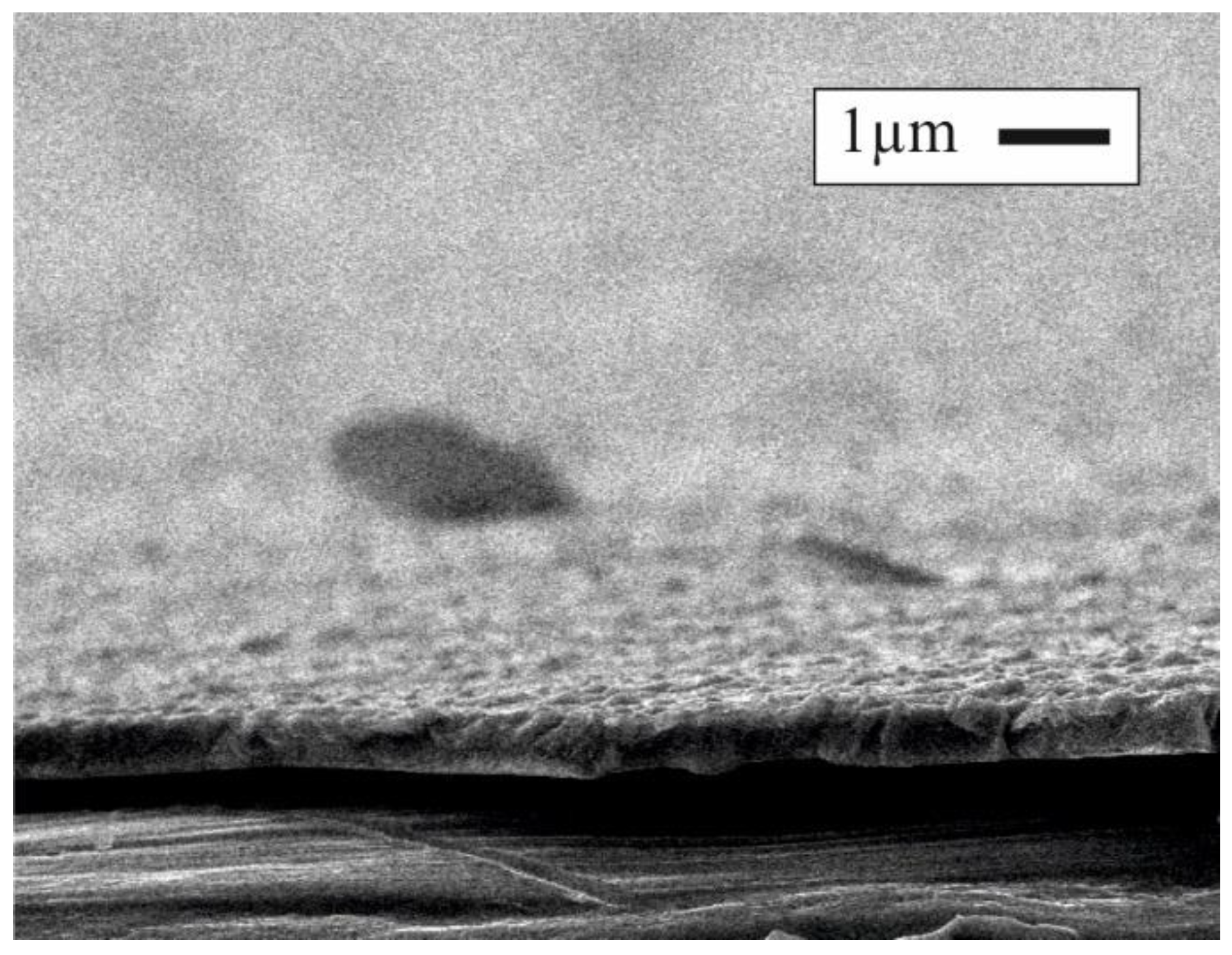
3.1. SEM Images

We studied the surface morphology of each layer of Au–Ru coatings with and without the Co–W sublayer and initial surface texture of the blades after electrochemical polishing. In Figure 5a–c, SEM images of Au–Ru coating are presented, and Figure 5a,d–f. shows such images of Au–Ru coating with Co–W sublayer. One can see that in the course of deposition the surface morphology of the layers undergoes significant changes and acquires a more developed surface texture. In the first sequence (a–b–c), after the deposition of the Au layer with a thickness of 700 nm, a pronounced globular structure with the lateral sizes of individual globules in the range of 0.5–2 µm is formed (Figure 5b). Then, after the deposition of the 250 nm Ru layer, a slight increase in the size of globules attended by a decrease in their number is observed (Figure 5c). In the second sequence (a–d–e–f), the deposition of the Co–W sublayer with a thickness of 400 nm (Figure 5d) and subsequent 300 nm Au layer (Figure 5e) does not result in the formation of the characteristic microstructural texture. However, the deposition of the outer 250 nm Ru layer (Figure 5f) again leads to the formation of a globular structure, similar to that in the first sequence. Thus, we should state that SEM study did not reveal a significant influence of the Co–W sublayer on the surface morphology of contact coatings.

3.2. Physical–Morphology Characteristics

We studied the porosity, microhardness and average roughness of the Au–Ru coatings using a statistical data collection method. As an example, Figure 6 shows an AFM image of the representative area of the Au layer of 300 nm in thickness. The Grain Analysis Code allowed the selection of two pores, the depth of which exceeded the thickness of the layer (these pores are indicated in the image by arrows). The results of this research are summarized in Table 2. One can see that the insertion of the Co–W sublayer significantly reduced surface porosity at the stage of Au-plating, and before the deposition of the outer Ru layer the difference is ca. 1.5%. The deposition of the Ru layer smoothed over this difference, and the porosity of both types of coatings became practically identical. This effect can be explained by the good covering and smoothing ability of the Ru electrolyte [8].
Further porosity investigation revealed a significant difference in the compromise corrosion potentials in HCl acid for fully formed coatings of both types. For the contact coatings with the Co–W sublayer Uc = 300–400 mV was found, while the coatings without the sublayer possessed Uc = 50–200 mV, which is close in value to the potential of the Fe–Ni substrate.
Statistical evaluation of the porosity data obtained for the Ru layer allowed the estimation of the distribution of the pore’s density N versus surface area S. The histogram presented in Figure 7 shows the predominance of pores with minimal areas (less than 0.3 µm2) for the contact coatings with the Co–W sublayer. The coatings without this sublayer were characterized mainly by the pores of medium size (0.2–0.4 µm2). Thus, it can be assumed that the corrosion potential of the coating in a larger measure depends on the size of the pores, but not on their total area.
The Co–W sublayer promotes the reduction in the average size of pores maintaining, at the same time, the overall thickness of the coatings. There are two probable reasons for this. Firstly, an increase in the number of layers in multilayer coatings decreases the overall porosity of the coatings [4]. Secondly, direct electroplating of Au on a permalloy substrate can stimulate the formation of local micro sized electrochemical cells in uncoated areas [5]. The difference between the standard potentials of a cathode (−0.35 V for Fe–Ni) and an anode (1.68 V for Au) can reach ca. 2 V. That is sufficient for the appearance of an electrical current, which localizes the anodic dissolution process at micro inclusions (pores) preventing their overgrowth.
In Table 2, one can see a rather sharp increase in the average surface roughness h from 20 to 32 nm after the deposition of the Au layer of 700 nm in thickness. At the same time, the introduction of the Co–W sublayer, keeping the same total thickness of the Co–W + Au layers, suppresses the h rise. In that case, the decreasing of the Au layer thickness prevents the development of specific growth structures on its surface. Some increase in microhardness of the contact coatings with the barrier layer, from 395 to 413 HV, can be explained by the hardness of Co–W alloys being twice as high as pure Au.

3.3. Transient Resistance

We studied three contact blades with the Co–W sublayer and three others without. The measurements were carried out at three randomly chosen points no fewer than five times. The statistically averaged dependencies of the transient resistance Rc on the pressing force Fp to the reference electrode are presented in Figure 8.
According to the known literature data for thin contact coatings [25,26], such dependencies should have a decreasing form with a constantly decreasing slope. However, the inflection points were observed in the curves shown in Figure 8. As noted in [23], a constant Rc decrease is associated with an increase in the total contact area and/or current passing area due to the surface modification and forming of the complementary texture on contacting surfaces. Partially, this can be due to the punching of oxide films as well. For Ru coatings, the second circumstance can be of prime importance. It is known [8,27] that in the course of Ru electrochemical deposition, a stable oxide film of 0.5–1 nm in thickness is immediately formed on its surface. Such a film prevents the formation of adsorbed organic polymer films possessing rather good electric conductivity, but still lower than the conductivity of the metal Ru. In this regards, the more significant change in the Rc-value observed for Au–Ru coatings, especially in the initial part of the Fp range, between 0.25 and 0.5 N, can be explained by the better ability to destroy oxide films. Surface modification and the forming of a complimentary texture on the contacting surface can also be facilitated by the lower microhardness value of Au–Ru coatings as compared with such coatings with a Co–W sublayer (395 HV as against 413 HV in Table 2). Thus, Au–Ru coatings exhibit a wider range of transient resistance variation (Figure 8) and possess a lower Rc-value equal to 12 mΩ.

3.4. Commutation Tests (Temporal Evolution of Transient Resistance)

We performed the commutation tests for commercial reed switches MKA-14 with contact blades covered by Au–Ru coating with and without a Co–W sublayer. Each tested batch consisted of five pieces. The Rc measurements were carried out in two modes: (1) low-power (50 mV, 5 μA, 50 Hz) after 2 × 10⁶ switching cycles and (2) mean-power (12 V, 0.25 A, 50 Hz) after 106 switching cycles. The commutation tests were stopped when Rc > 0.1 Ω. This value is an upper permissible limit restricting operability for most commercial low- and mean-power reed switches.
Temporal Rc evolution curves for the low-power mode are presented in Figure 9a. For both types of coatings, these curves exhibit an initial slow decay, then stabilization, and, finally, a rise after reaching the number of cycles of (6–8) × 106. For the Au–Ru coating, the permissible level was (1.3 ± 0.2) × 107 cycles and for the Au–Ru coating with a Co–W sublayer it was (1.7 ± 0.2) × 107 cycles. One can see that the coatings with the barrier layer are able to provide a higher number of switching cycles with a lower Rc-value in the second half of the test interval, after 107 cycles. However, in the first half, with the exception of a small initial part, Au–Ru coatings are characterized by a lower Rc-value, at an average of 0.01 Ω lower.
Various characteristics of the contact coatings such as erosion, corrosion and thermal resistance, microhardness, porosity, roughness, etc., can influence the transient resistance and service time of reed switches (see, for example, [1,4,22,23] and the references cited therein). However, for low- and mean-power switches, the most important are porosity and roughness. From that viewpoint, the decrease in the starting Rc in Figure 9 is mainly determined by an initial level of roughness of the contacting surfaces, which creates a larger current passing area for Au–Ru coatings. Such a surface texture allows a stable Rc-value to be kept within the range of (2–6) × 107 switching cycles. Then, the Rc-value starts to rise with an increase in the number of the switching cycles. That rise is mainly determined by the porosity of the coatings. Besides, an increasing role starts to play the centers of corrosion and the areas with low electrical conductivity—oxides, hydroxides, sulfide and other contaminations forming via the penetration of substrate materials into the contact area.
The curves shown in Figure 9b for the mean-power mode are slightly different to those presented in Figure 9a. The difference is in the service time, i.е., in the allowable level of switching cycles (when Rc < 0.1 Ω). For Au–Ru coatings this level is (4.9 ± 0.1) × 106, and for the coatings with a Co–W sublayer it is higher, of (6.7 ± 0.1) × 106 cycles. For both types of coatings, those levels are half the numbers measured for the low-power mode. Moreover, there is no strongly pronounced part on the curves Rc (n) in which the transient resistance of the Au–Ru coating is significantly less than that for the coatings with the Co–W sublayer.

4. Conclusions

In this work, we have studied the roughness, porosity and microhardness of electrodeposited Au–Ru coatings with and without a Co–W alloy barrier sublayer. Commutation tests (temporal evolution of transient resistance) of commercially produced MKA-14 reed switches equipped with these contact blades were carried out in low- and mean-power modes. It was found that the Co–W sublayer allows an increase in the service life and minimizes the transient resistance along with a decrease in the prime cost of reed switch production.
The main experimental results of our study can be summarized as follows.
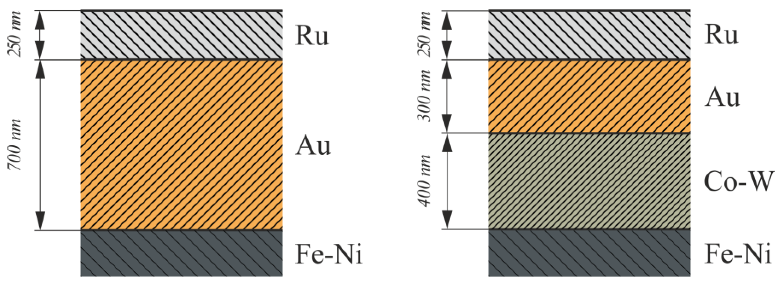
  • The Co–W barrier sublayer reduced the average roughness of Au–Ru coatings from 35 to 32 nm and increased their microhardness from 395 to 413 HV. At the same time, the porosity of such coatings did not change significantly, namely, from 4.1% to 3.9%, but average pore sizes decreased.
  • The blades with Au–Ru coatings without a Co–W sublayer exhibited a greater variation in the transient resistance during an increase in the pressing force within the range of 0.25–1 N with a lower Rc-value equal to 12 mΩ.
  • The Co–W barrier sublayer increased the service time of the tested reed switches: in the low-power mode by more than 4 × 10⁶ switching cycles, and in mean-power mode by more than 1.8 × 10⁶ switching cycles.

Author Contributions

Conceptualization, G.P.G.; validation, D.V.S. and S.M.K.; investigation, G.P.G. and E.V.S.; writing—draft preparation, G.P.G., editing—final version preparation, A.T. All authors have read and agreed to the published version of the manuscript.

Funding

This work was supported by the Ministry of Education and Science of the Russian Federation in the frame of the state assignment FSSN-2020-0003.

Institutional Review Board Statement

Not applicable.

Informed Consent Statement

Not applicable.

Data Availability Statement

Not applicable.

Acknowledgments

The Regional Center for Probe Microscopy for collective use of the Utkin Ryazan State Radio Engineering University (Ryazan, Russian Federation) and, personally, Nikolay B. Rubin for the SEM measurements, are highly appreciated.

Conflicts of Interest

The authors declare no conflict of interest.

References

  1. Shishkina, L.; Lokshtanova, O.G.; Karabanov, S.M. Electroplated Coatings for Magnetically Operated Contacts (Reed Switches). Coatings 2012, 2, 1–7. [Google Scholar] [CrossRef]
  2. Murugan, V.K.; Jia, Z.; Syaranamual, G.J.; Gan, C.L.; Huang, Y.; Chen, Z. An investigation into different nickel and nickel–phosphorus stacked thin coatings for the corrosion protection of electrical contacts. Surf. Coat. Technol. 2016, 300, 95–103. [Google Scholar] [CrossRef]
  3. Aliofkhazraei, M.; Frank, C.; Zangari, W.G.; Köçkar, H.; Alper, M.; Rizal, C.; Magagnin, L.; Protsenko, V.; Arunachalam, R.; Rezvanian, A.; et al. Development of electrodeposited multilayer coatings: A review of fabrication, microstructure, properties and applications. Appl. Surf. Sci. Adv. 2021, 6, 100141. [Google Scholar] [CrossRef]
  4. Braunovich, M.; Konchits, V.V.; Myshkin, N.K. Electrical Contacts; CRC Press Taylor & Francis Group: Boca Raton, FL, USA, 2013. [Google Scholar]
  5. Gamburg, Y.D. Electrochemical Crystallization of Metals and Alloys; Yanus-K: Moscow, Russia, 1997; 384p. (In Russian) [Google Scholar]
  6. Karabanov, S.М.; Suvorov, D.V. Ruthenium Based Nanoscale Contact Coatings for Magnetically Controlled MEMS Switches. Int. J. Mechan. Mater. Eng. 2019, 3, 170–173. [Google Scholar]
  7. Ralbag, N.; Felner, I.; Avnir, D. New reed switch design based on magnetic silver. Mater. Res. Express 2019, 6, 126329. [Google Scholar] [CrossRef]
  8. Karabanov, S.М.; Lokshtanova, О.G. Complex composition of the sulphamate electrolytes used for ruthenium coating. Zh. Prikl. Khimii 2008, 18, 961–964. (In Russian) [Google Scholar]
  9. Bernasconi, R.; Lucotti, A.; Nobili, L.; Magagnin, L. Ruthenium Electrodeposition from Deep Eutectic Solvents. J. Electrochem. Soc. 2018, 165, D620. [Google Scholar] [CrossRef]
  10. William, D.S.; Qiang, H. Ruthenium Electrodeposition from Water-in-Salt Electrolytes and the Influence of Tetrabutylammonium. J. Electrochem. Soc. 2020, 167, 062509. [Google Scholar]
  11. Shishkina, L.; Karabanov, S.M.; Lokshtanova, O.G. Experience of Development and Application of the Electroplated Coatings Used in the Industrial Production of Magnetically Operated Contacts (Reed Switches). Electropl. Surf. Treat. 2011, 2, 20–26. (In Russian) [Google Scholar]
  12. Kondati-Natarajan, S.; Nies, C.-L.; Nolan, M. The role of Ru passivation and doping on the barrier and seed layer properties of Ru-modified TaN for copper interconnects. J. Chem. Phys. 2020, 152, 144701. [Google Scholar] [CrossRef] [PubMed]
  13. Li, Z.; Tian, Y.; Teng, C.; Cao, H. Recent Advances in Barrier Layer of Cu Interconnects. Materials 2020, 13, 5049. [Google Scholar] [CrossRef] [PubMed]
  14. Popczyk, M.; Łosiewicz, B. The Influence of Current Density of Electrodeposition on the Electrochemical Properties of Ni-Mo Alloy Coatings. Solid State Phenom. 2015, 228, 269–272. [Google Scholar] [CrossRef]
  15. Ma, L.; Xi, X.; Nie, Z.; Dong, T.; Mao, Y. Electrodeposition and Characterization of Co-W Alloy from Regenerated Tungsten Salt. Int. J. Electrochem. Sci. 2017, 12, 1034–1051. [Google Scholar] [CrossRef]
  16. Allahyarzadeh, M.H.; Aliofkhazraei, M.; Rezvanian, A.R.; Torabinejad, V.; Sabour Rouhaghdam, A.R. Ni–W electrodeposited coatings: Characterization, properties and applications. Surf. Coat. Technol. 2016, 307, 978–1010. [Google Scholar] [CrossRef]
  17. Lee, H.B. Synergy between corrosion and wear of electrodeposited Ni–W coating. Tribol. Lett. 2013, 50, 407–419. [Google Scholar] [CrossRef]
  18. Udompanit, N.; Wangyao, P.; Henpraserttae, S.; Boonyongmaneerat, Y. Wear response of composition-modulated multilayer Ni–W coatings. Adv. Mater. Res. 2014, 1025–1026, 302–309. [Google Scholar] [CrossRef]
  19. Suvorov, D.V.; Gololobov, G.P.; Tarabrin, D.Y.; Slivkin, E.V.; Karabanov, S.M.; Tolstoguzov, A.B. Electrochemical Deposition of Ni–W Crack-Free Coatings. Coatings 2018, 8, 233. [Google Scholar] [CrossRef] [Green Version]
  20. Kublanovsky, V.S.; Yapontseva, Y.S. Electrocatalytic Properties of Co-Mo Alloys Electrodeposited from a Citrate-Pyrophosphate Electrolyte. Electrocatalysis 2014, 5, 372–378. [Google Scholar] [CrossRef] [Green Version]
  21. Tsyntsarua, N.; Cesiulis, H.; Pellicer, E.; Celis, J.-P.; Sort, J. Structural, magnetic, and mechanical properties of electrodeposited cobalt-tungsten alloys: Intrinsic and extrinsic interdependencies. Electrochim. Acta 2013, 104, 94–103. [Google Scholar] [CrossRef]
  22. Shishkina, L.; Lokshtanova, O.G. Electroplated Coatings for Reed Switches. Bull. SPbSTI 2011, 11, 122–125. (In Russian) [Google Scholar]
  23. Karabanov, S.M.; Verlov, N.A.; Suvorov, D.V.; Gololobov, G.P.; Slivkin, E.V. Properties of contact coatings based on ruthenium nanofilms for MEMS switches. Tech. Phys. Lett. 2015, 14, 56–63. [Google Scholar] [CrossRef]
  24. Gololobov, G.P.; Arefiev, A.S.; Tregulov, V.R.; Utochkin, I.G.; Kireeva, O.V. The study of the surfaces of magnetically controlled contacts by atomic force microscopy. Vestn. RGRTU 2003, 13, 66–69. (In Russian) [Google Scholar]
  25. Gololobov, G.P.; Suvorov, D.V.; Serpova, M.A.; Arefiev, A.S. The study of contact electrical resistance of coatings on the basis of refractory metal alloys Co-W, Co-Mo, Ni-W, Ni-Mo. J. Phys. Conf. Ser. 2020, 889, 012017. [Google Scholar] [CrossRef]
  26. Pyatin, Y.M. Materials in Instrumentation and Automation; Mashinostroenie: Moscow, Russia, 1982; 528p. (In Russian) [Google Scholar]
  27. Jones, T. Electroplating of ruthenium. Met. Finish. 2001, 6, 121–128. [Google Scholar] [CrossRef]
Figure 1. The structure of Au–Ru layers-based contact coatings with and without Co–W barrier sublayer.
Coatings 12 00161 g001
Figure 2. General view (a) and design of reed switch MKA-14 (b): (1) permalloy contact blades, (2) glass envelope. The dimensions are shown in mm.
Coatings 12 00161 g002
Figure 3. SEM image of the cross section of a slice of contact blade after the deposition of Au sublayer of 700 nm in thickness.
Coatings 12 00161 g003
Figure 4. Schematic view of pore selection by the horizontal plane section.
Coatings 12 00161 g004
Figure 5. SEM images of surface morphology of the different layers deposited on the contact blades. The sequence (abc) was acquired for Au–Ru coatings: (a) initial Fe–Ni polished surface, (b) Au layer, (c) Ru layer. The sequence (adef) was acquired for Au–Ru coatings with Co–W sublayer: (a) initial Fe–Ni polished surface, (d) Co–W sublayer, (e) Au layer, (f) Ru layer.
Coatings 12 00161 g005
Figure 6. AFM image of the representative area of Au layer of 300 nm in thickness. The image processing code was used to select two pores, the depth of which exceeded the thickness of the layer (these pores are shown by arrows).
Coatings 12 00161 g006
Figure 7. Statistical distribution of the pore’s density versus their area for two types of coatings.
Coatings 12 00161 g007
Figure 8. Transient resistance Rc versus the pressing force Fp for Au–Ru contact coatings with and without Co–W sublayer.
Coatings 12 00161 g008
Figure 9. Temporal evaluation of Rc-value in the course of the commutation tests for MKA-14 reed switches with Au–Ru and Au –(Co–W)–Ru: (a) low-power mode (50 mV, 5 μA, 50 Hz), (b) mean-power mode (12 V, 0.25 A, 50 Hz).
Coatings 12 00161 g009
Table 1. The electrolytes’ composition and characteristics of deposition modes.
Deposition
Characteristic
Layers
Co–WAuRu
Composition and concentration of electrolytes, g·dm−3CoSO4–56
Na2WO4–99
C6H8O7–80
H3BO4–40
C12H25SO4Na–1
K[Au(CN)2]–10
KH2PO4–45
K2HPO4–150
K3C6H5O7–65
ТlН2РO4–0.8
(NH4)3[Ru2(µ-N)(H2O)2Cl8]–15 (NH4)2 SO4–50
Current density, mA·cm−25–151–2.510–30
pH75.5–6.51.5–2.0
Temperature, °C606060
Table 2. Physical–morphology characteristics of the coating layers.
CharacteristicAu–Ru CoatingsAu–Ru Coatings with Co–W Sublayer
Fe–NiAuRuFe–NiCo–WAuRu
Area of pores ρ, %-5.84.1-6.24.43.9
Roughness h, nm20323520252832
Microhardness, HV345354395345420371413
Publisher’s Note: MDPI stays neutral with regard to jurisdictional claims in published maps and institutional affiliations.

