
Damage Identification for Shear-Type Structures Using the Change of Generalized Shear Energy

Abstract
:1. Introduction
2. Theoretical Development
2.1. Modal Strain Energy
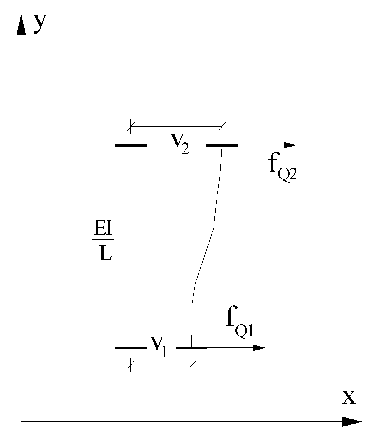
2.2. Generalized Shear Energy
2.3. Mode Shape Expansion
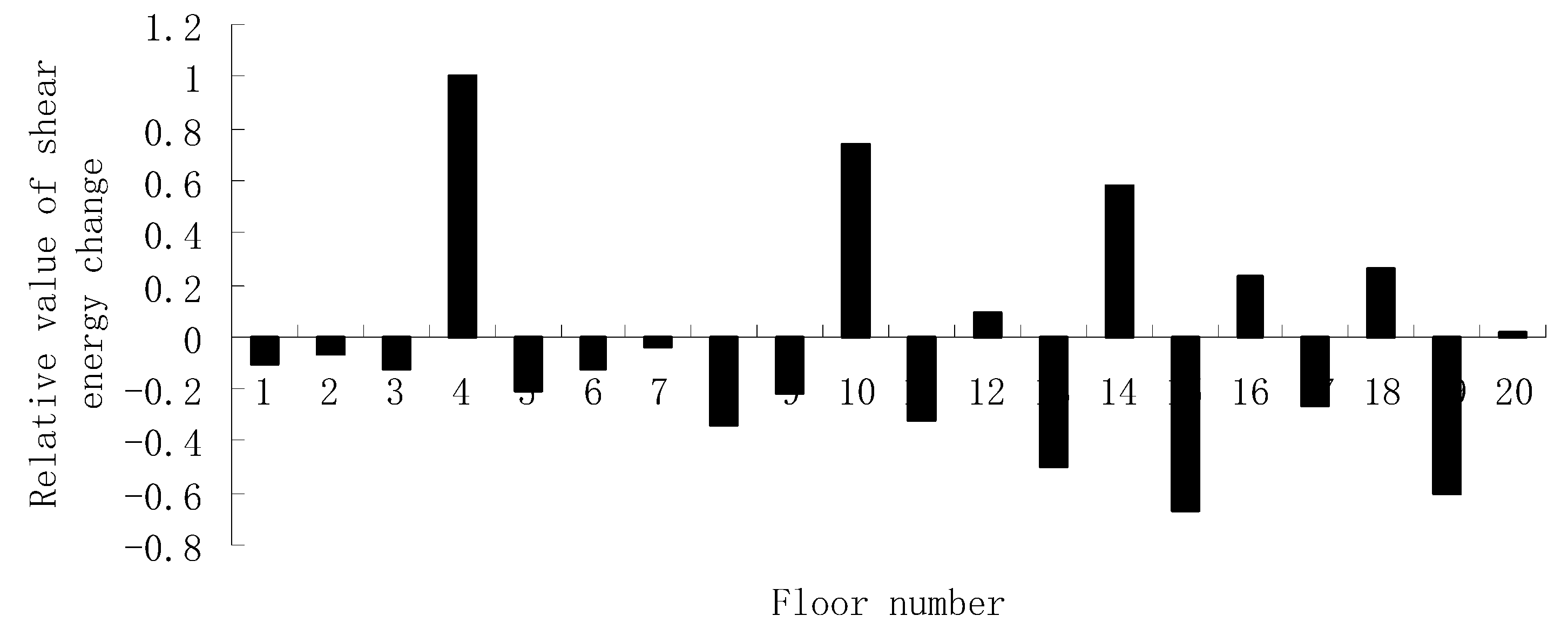
3. Numerical Verification
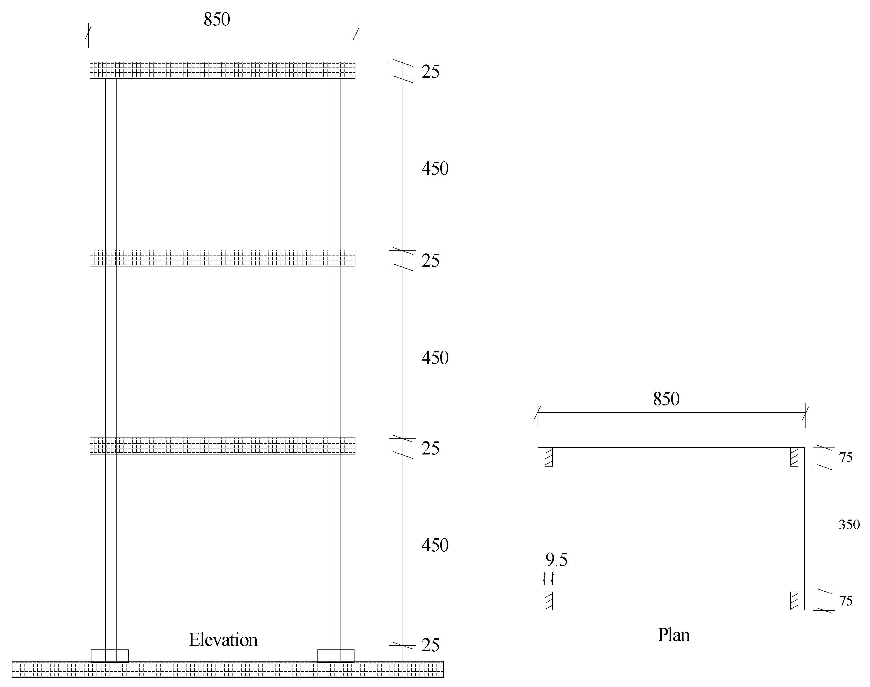
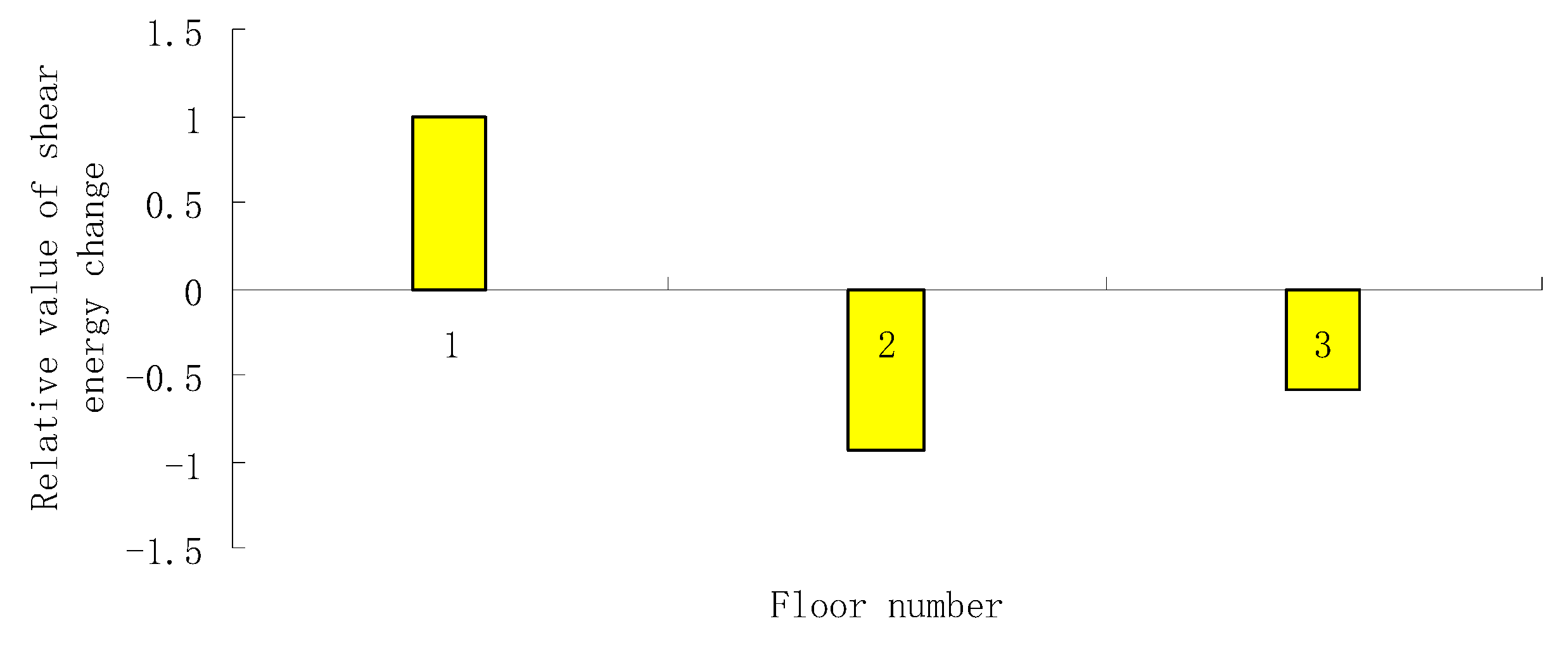
4. Experimental Verification
5. Conclusions
Author Contributions
Funding
Institutional Review Board Statement
Informed Consent Statement
Data Availability Statement
Conflicts of Interest
References
- Fan, W.; Qiao, P. Vibration-based damage identification methods: A review and comparative study. Struct. Health Monit. 2011, 10, 83–111. [Google Scholar] [CrossRef]
- Alvandi, A.; Cremona, C. Assessment of vibration-based damage identification techniques. J. Sound Vib. 2006, 292, 179–202. [Google Scholar] [CrossRef]
- Ierimonti, L.; Cavalagli, N.; Venanzi, I.; García-Macías, E.; Ubertini, F. A transfer Bayesian learning methodology for structural health monitoring of monumental structures. Eng. Struct. 2021, 247, 113089. [Google Scholar] [CrossRef]
- Yang, Q.W.; Sun, B.X. Structural damage localization and quantification using static test data. Struct. Health Monit. 2011, 10, 381–389. [Google Scholar] [CrossRef]
- Lee, E.T.; Eun, H.C. Damage detection of damaged beam by constrained displacement curvature. J. Mech. Sci. Technol. 2008, 22, 1111–1120. [Google Scholar] [CrossRef]
- Cui, H.; Xu, X.; Peng, W.; Zhou, Z.; Hong, M. A damage detection method based on strain modes for structures under ambient excitation. Measurement 2018, 125, 438–446. [Google Scholar] [CrossRef]
- Chen, G.; Mu, H.; Pommerenke, D.; Drewniak, J.L. Damage detection of reinforced concrete beams with novel distributed crack/strain sensors. Struct. Health Monit. 2004, 3, 225–243. [Google Scholar] [CrossRef]
- Peng, X.; Yang, Q.W. Sensor Placement and Structural Damage Evaluation by Improved Generalized Flexibility. IEEE Sens. J. 2021, 21, 11654–11664. [Google Scholar] [CrossRef]
- Yang, Q.; Peng, X. Sensitivity Analysis Using a Reduced Finite Element Model for Structural Damage Identification. Materials 2021, 14, 5514. [Google Scholar] [CrossRef]
- Lu, Z.R.; Wang, L. An enhanced response sensitivity approach for structural damage identification: Convergence and performance. Int. J. Numer. Methods Eng. 2017, 111, 1231–1251. [Google Scholar] [CrossRef]
- Yang, Q.W.; Liu, J.K. Structural damage identification based on residual force vector. J. Sound Vib. 2007, 305, 298–307. [Google Scholar] [CrossRef]
- Hosseinzadeh, A.Z.; Amiri, G.G.; Abyaneh, M.J.; Razzaghi, S.A.S.; Hamzehkolaei, A.G. Baseline updating method for structural damage identification using modal residual force and grey wolf optimization. Eng. Optim. 2019, 52, 549–566. [Google Scholar] [CrossRef]
- He, L.; Lian, J.; Ma, B. Intelligent damage identification method for large structures based on strain modal parameters. J. Vib. Control 2014, 20, 1783–1795. [Google Scholar] [CrossRef]
- Yu, Y.; Wang, C.; Gu, X.; Li, J. A novel deep learning-based method for damage identification of smart building structures. Struct. Health Monit. 2019, 18, 143–163. [Google Scholar] [CrossRef] [Green Version]
- Doebling, S.W.; Farrar, C.R.; Prime, M.B. A summary review of vibration-based damage identification methods. Shock Vib. Dig. 1998, 30, 91–105. [Google Scholar] [CrossRef] [Green Version]
- Cornwell, P.; Doebling, S.W.; Farrar, C.R. Application of the strain energy damage detection method to plate-like structures. J. Sound Vib. 1999, 224, 359–374. [Google Scholar] [CrossRef]
- Shi, Z.Y.; Law, S.S.; Zhang, L.M. Structural damage detection from modal strain energy change. J. Eng. Mech. 2000, 126, 1216–1223. [Google Scholar] [CrossRef]
- Shi, Z.Y.; Law, S.S.; Zhang, L.M. Improved damage quantification from elementary modal strain energy change. J Eng Mech-Asce 2002, 128, 521–529. [Google Scholar] [CrossRef]
- Hu, H.; Wang, B.-T.; Lee, C.-H.; Su, J.-S. Damage detection of surface cracks in composite laminates using modal analysis and strain energy method. Compos. Struct. 2006, 74, 399–405. [Google Scholar] [CrossRef]
- Hu, H.; Wang, J. Damage detection of a woven fabric composite laminate using a modal strain energy method. Eng. Struct. 2009, 31, 1042–1055. [Google Scholar] [CrossRef]
- Hu, H.; Wu, C. Development of scanning damage index for the damage detection of plate structures using modal strain energy method. Mech. Syst. Signal Processing 2009, 23, 274–287. [Google Scholar] [CrossRef]
- Yan, W.J.; Ren, W.X.; Huang, T.L. Statistic structural damage detection based on the closed-form of element modal strain energy sensitivity. Mech. Syst. Signal Processing 2012, 28, 183–194. [Google Scholar] [CrossRef]
- Entezami, A.; Shariatmadar, H. Damage detection in structural systems by improved sensitivity of modal strain energy and Tikhonov regularization method. Int. J. Dyn. Control 2014, 2, 509–520. [Google Scholar] [CrossRef] [Green Version]
- Moradi Pour, P.; Chan, T.; Gallage, C. An improved modal strain energy method for structural damage detection, 2D simulation. Struct. Eng. Mech. 2015, 54, 105–119. [Google Scholar] [CrossRef] [Green Version]
- Cha, Y.J.; Buyukozturk, O. Structural damage detection using modal strain energy and hybrid multiobjective optimization. Comput.-Aided Civ. Infrastruct. Eng. 2015, 30, 347–358. [Google Scholar] [CrossRef]
- Vo-Duy, T.; Ho-Huu, V.; Dang-Trung, H.; Dinh-Cong, D.; Nguyen-Thoi, T. Damage detection in laminated composite plates using modal strain energy and improved differential evolution algorithm. Procedia Eng. 2016, 142, 182–189. [Google Scholar] [CrossRef]
- Vo-Duy, T.; Ho-Huu, V.; Dang-Trung, H.; Nguyen-Thoi, T. A two-step approach for damage detection in laminated composite structures using modal strain energy method and an improved differential evolution algorithm. Compos. Struct. 2016, 147, 42–53. [Google Scholar] [CrossRef]
- Li, Y.; Wang, S.; Zhang, M.; Zheng, C. An improved modal strain energy method for damage detection in offshore platform structures. J. Mar. Sci. Appl. 2016, 15, 182–192. [Google Scholar] [CrossRef]
- Liu, G.; Zhai, Y.; Leng, D.; Tian, X.; Mu, W. Research on structural damage detection of offshore platforms based on grouping modal strain energy. Ocean Eng. 2017, 140, 43–49. [Google Scholar] [CrossRef]
- Xu, M.; Wang, S. Cross modal strain energy–based structural damage detection in the presence of noise effects. Adv. Mech. Eng. 2017, 9, 1687814017744122. [Google Scholar] [CrossRef]
- Wu, S.; Zhou, J.; Rui, S.; Fei, Q. Reformulation of elementary modal strain energy method based on strain modes for structural damage detection. Adv. Struct. Eng. 2017, 20, 896–905. [Google Scholar] [CrossRef]
- Kaveh, A.; Zolghadr, A. Cyclical parthenogenesis algorithm for guided modal strain energy based structural damage detection. Appl. Soft Comput. 2017, 57, 250–264. [Google Scholar] [CrossRef]
- Ghasemi, M.R.; Nobahari, M.; Shabakhty, N. Enhanced optimization-based structural damage detection method using modal strain energy and modal frequencies. Eng. Comput. 2018, 34, 637–647. [Google Scholar] [CrossRef]
- Ashory, M.R.; Ghasemi-Ghalebahman, A.; Kokabi, M.J. An efficient modal strain energy-based damage detection for laminated composite plates. Adv. Compos. Mater. 2018, 27, 147–162. [Google Scholar] [CrossRef]
- Teng, S.; Chen, G.; Liu, G.; Lv, J.; Cui, F. Modal strain energy-based structural damage detection using convolutional neural networks. Appl. Sci. 2019, 9, 3376. [Google Scholar] [CrossRef] [Green Version]
- Teng, S.; Chen, G.; Gong, P.; Liu, G.; Cui, F. Structural damage detection using convolutional neural networks combining strain energy and dynamic response. Meccanica 2020, 55, 945–959. [Google Scholar] [CrossRef]
- Zhu, H.; Li, L.; He, X.Q. Damage detection method for shear buildings using the changes in the first mode shape slopes. Comput. Struct. 2011, 89, 733–743. [Google Scholar] [CrossRef]
- Xing, Z.H.; Mita, A. A substructure approach to local damage detection of shear structure. Struct. Control Health Monit. 2012, 19, 309–318. [Google Scholar] [CrossRef]
- Aloisio, A.; Di Battista, L.; Alaggio, R.; Fragiacomo, M. Sensitivity analysis of subspace-based damage indicators under changes in ambient excitation covariance, severity and location of damage. Eng. Struct. 2020, 208, 110235. [Google Scholar] [CrossRef]
- Aloisio, A.; Di Battista, L.; Alaggio, R.; Antonacci, E.; Fragiacomo, M. Assessment of structural interventions using Bayesian updating and subspace-based fault detection methods: The case study of S. Maria di Collemaggio basilica, L’Aquila, Italy. Struct. Infrastruct. Eng. 2021, 17, 141–155. [Google Scholar] [CrossRef]
- Niu, Z. Two-step structural damage detection method for shear frame structures using FRF and Neumann series expansion. Mech. Syst. Signal Processing 2021, 149, 107185. [Google Scholar] [CrossRef]
- Nguyen-Ngoc, L.; Tran, H.; Bui-Tien, T.; Mai-Duc, A.; Wahab, M.A.; Nguyen, H.X.; De Roeck, G. Damage detection in structures using particle swarm optimization combined with artificial neural network. Smart Struct. Syst. 2021, 28, 1–12. [Google Scholar]
- Yang, Q.W.; Peng, X. An exact method for calculating the eigenvector sensitivities. Appl. Sci. 2020, 4, 2577. [Google Scholar] [CrossRef] [Green Version]
- Yang, Q.W. Model reduction by Neumann series expansion. Appl. Math. Model. 2009, 33, 4431–4434. [Google Scholar] [CrossRef] [Green Version]
- Li, L. Numerical and Experimental Studies of Damage Detection for Shear Buildings. Ph.D Thesis, Huazhong University of Science and Technology, Wuhan, China, 2005. [Google Scholar]


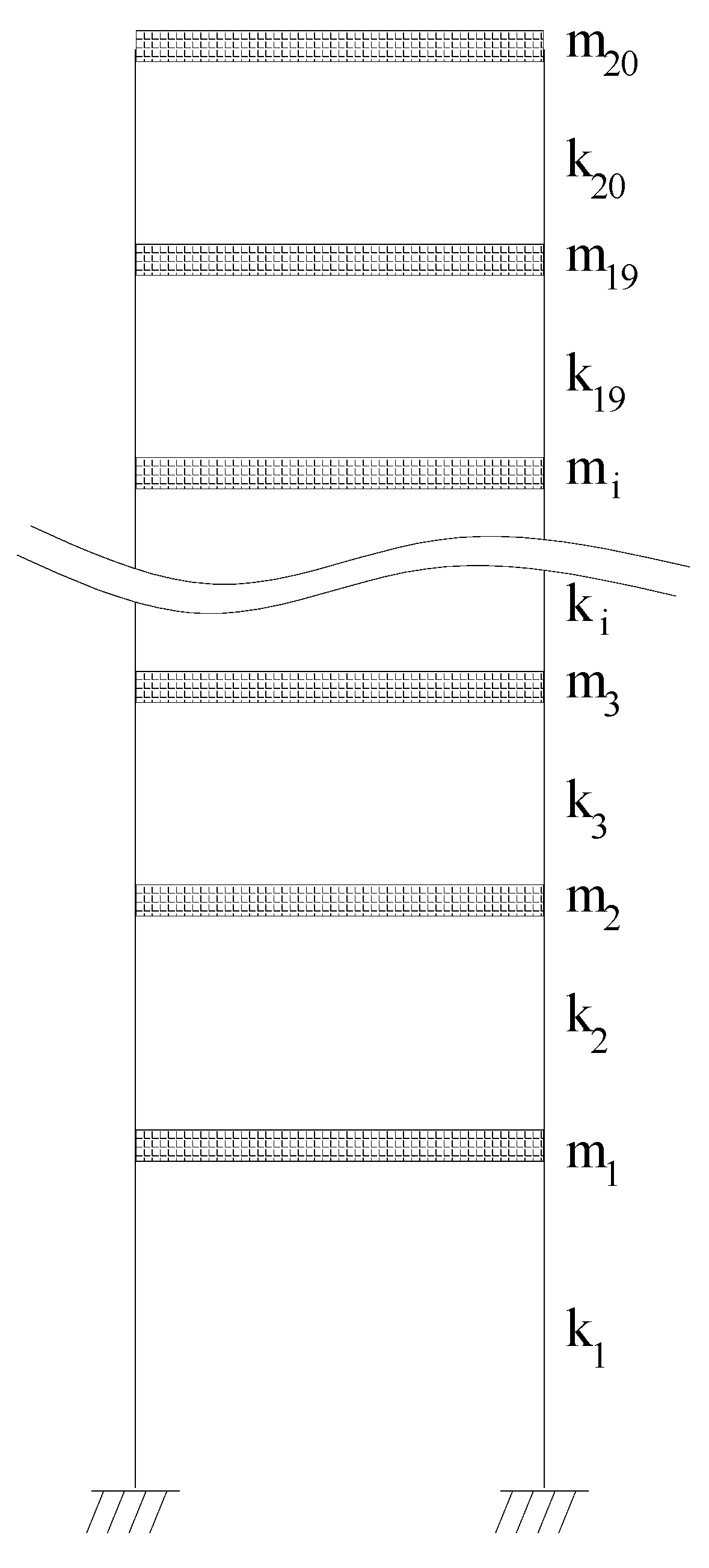
| Shear structures | |
| Two storeys | |
| Three storeys | |
| Four storeys |
| Damage Case | Element Number | Stiffness Reduction |
|---|---|---|
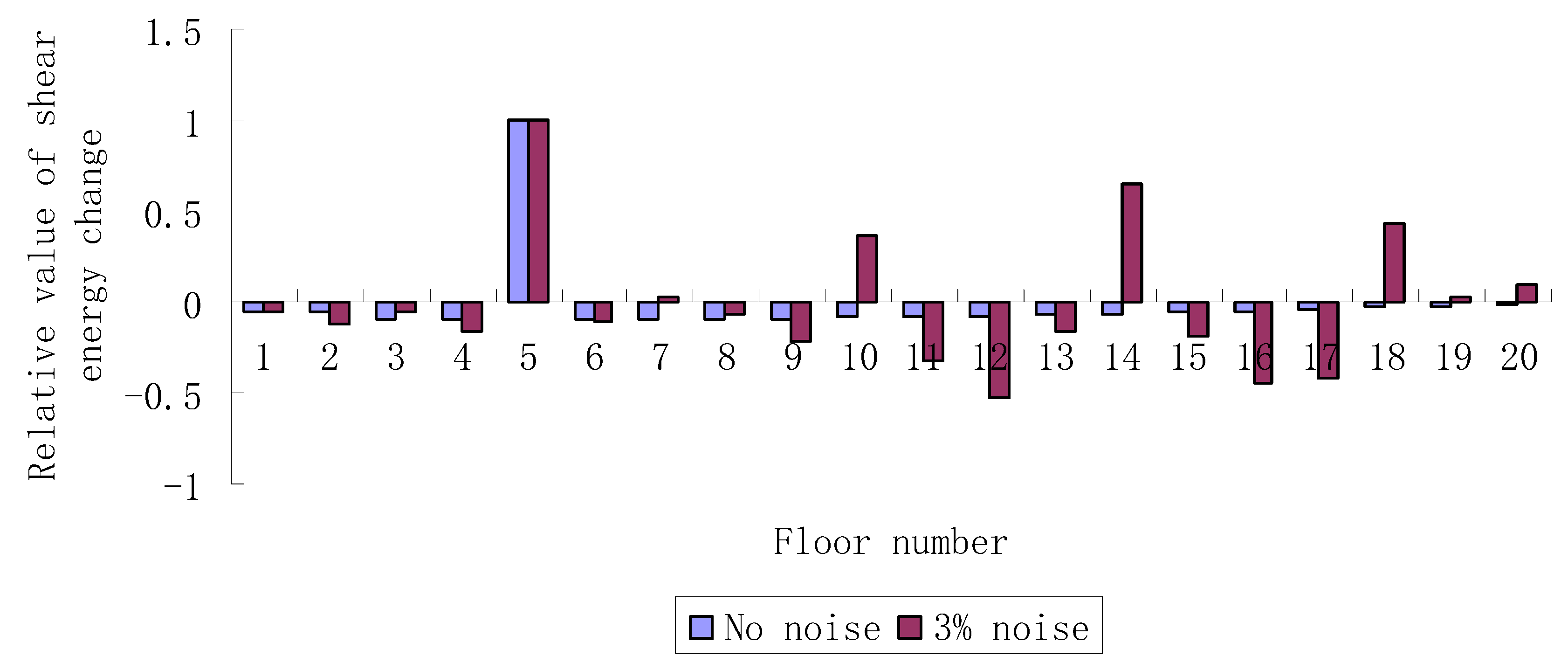
| Case 1 | 5 | 20% |
| Case 2 | 3, 12 | 10%, 15% |
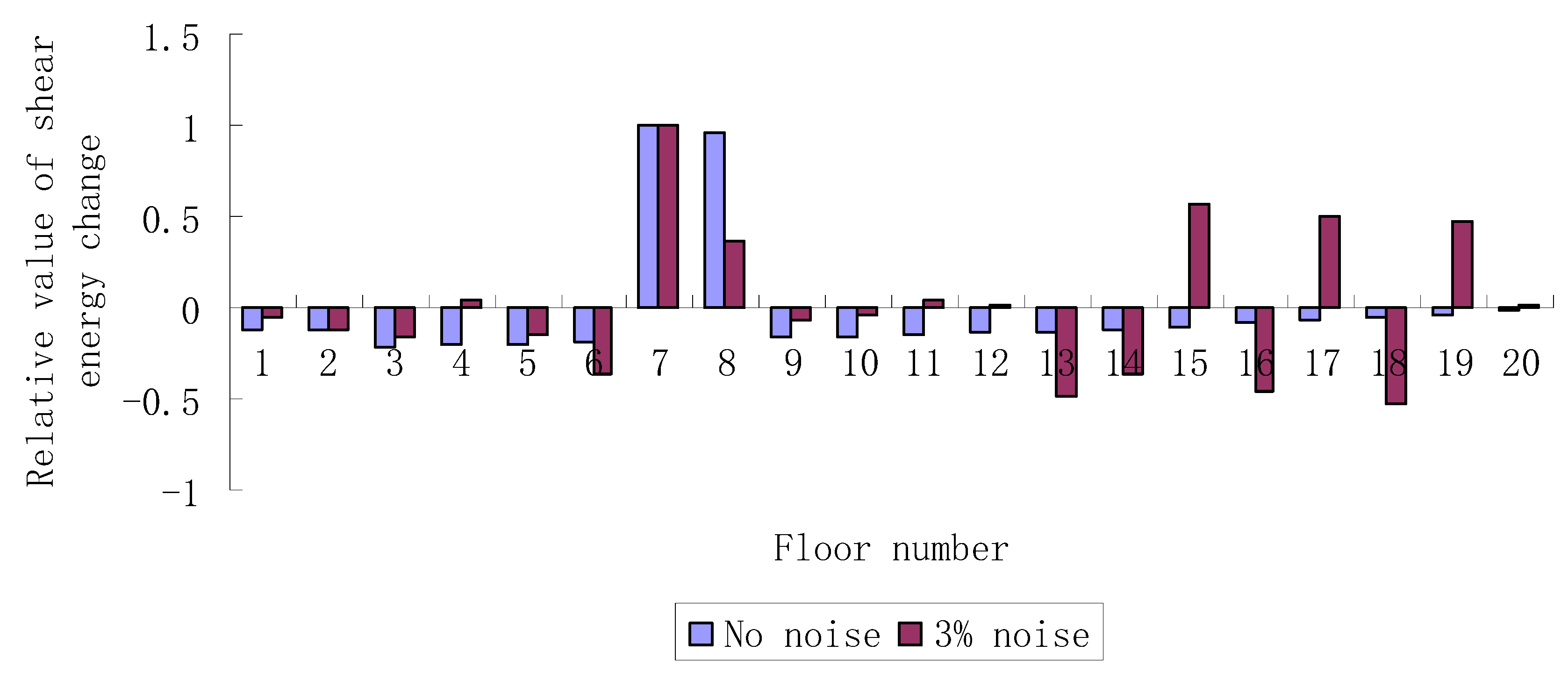
| Case 3 | 7, 8 | 20%, 20% |
| Case 4 | 4, 10 | 15%, 12% |
| = 0.2072 | = 0.2130 | = 0.1787 | = 0.3596 | = 0.2015 |
| = 0.2085 | = 0.1891 | = 0.2965 | = 0.0474 | = 0.4416 |
| = 0.0932 | = 0.3936 | = −0.0246 | = 0.3309 | = 0.4444 |
| = −0.1734 | = −0.0342 | = 0.3648 | = 0.4819 | = 0.4175 |
Publisher’s Note: MDPI stays neutral with regard to jurisdictional claims in published maps and institutional affiliations. |
© 2022 by the authors. Licensee MDPI, Basel, Switzerland. This article is an open access article distributed under the terms and conditions of the Creative Commons Attribution (CC BY) license (https://creativecommons.org/licenses/by/4.0/).
Share and Cite
Sun, Y.; Yang, Q.; Peng, X. Damage Identification for Shear-Type Structures Using the Change of Generalized Shear Energy. Coatings 2022, 12, 192. https://doi.org/10.3390/coatings12020192
Sun Y, Yang Q, Peng X. Damage Identification for Shear-Type Structures Using the Change of Generalized Shear Energy. Coatings. 2022; 12(2):192. https://doi.org/10.3390/coatings12020192
Chicago/Turabian StyleSun, Yun, Qiuwei Yang, and Xi Peng. 2022. "Damage Identification for Shear-Type Structures Using the Change of Generalized Shear Energy" Coatings 12, no. 2: 192. https://doi.org/10.3390/coatings12020192