
Long-Term Durability of Robust Super-Hydrophobic Co–Ni-Based Coatings Produced by Electrochemical Deposition


Abstract
:1. Introduction
2. Materials and Methods
3. Results and Discussion
3.1. Surface Wetting Property of Two Super-Hydrophobic Coatings with Immersion Time
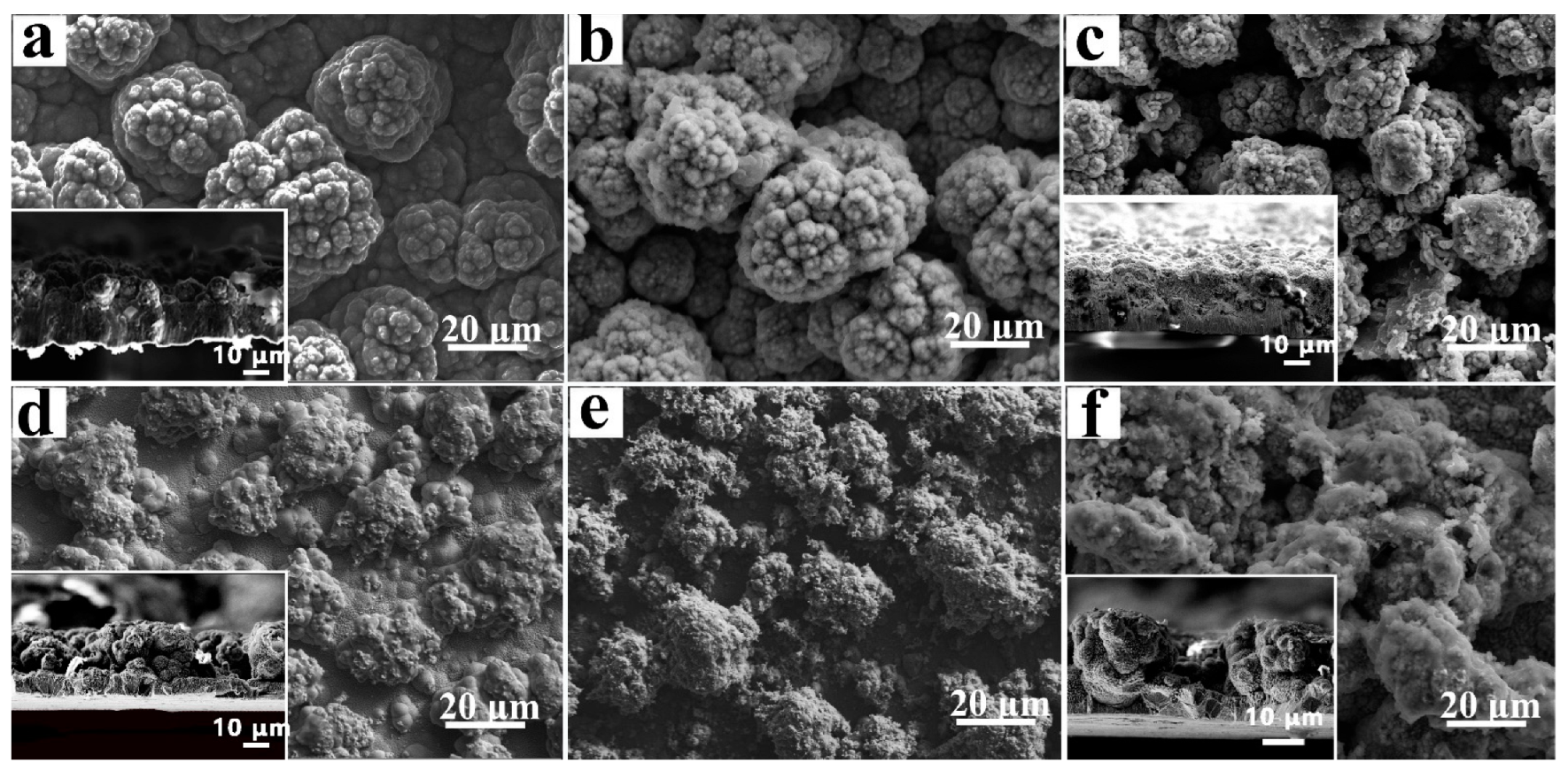
3.2. Surface Morphology of Two Super-Hydrophobic Coatings with Immersion Time
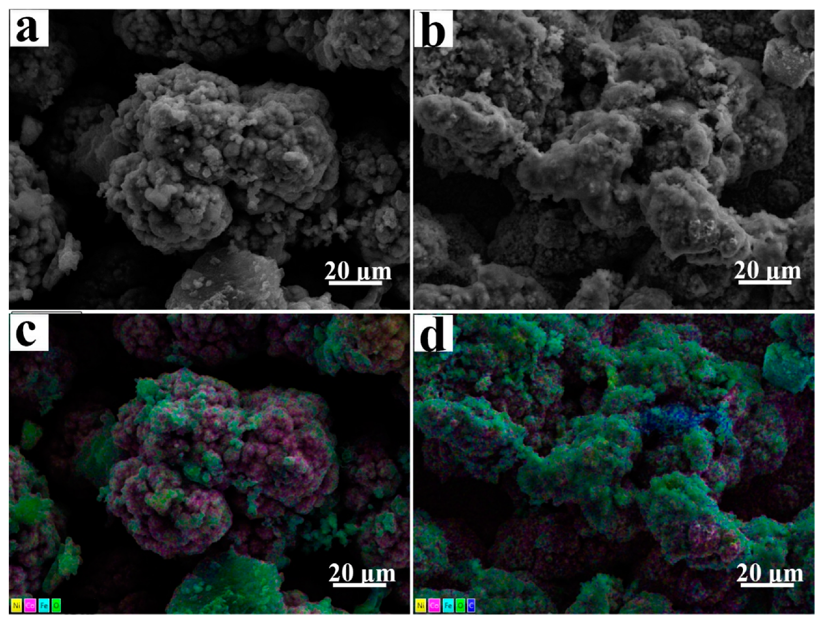
3.3. Elements Distribution on Coating Surfaces after Immersion Test
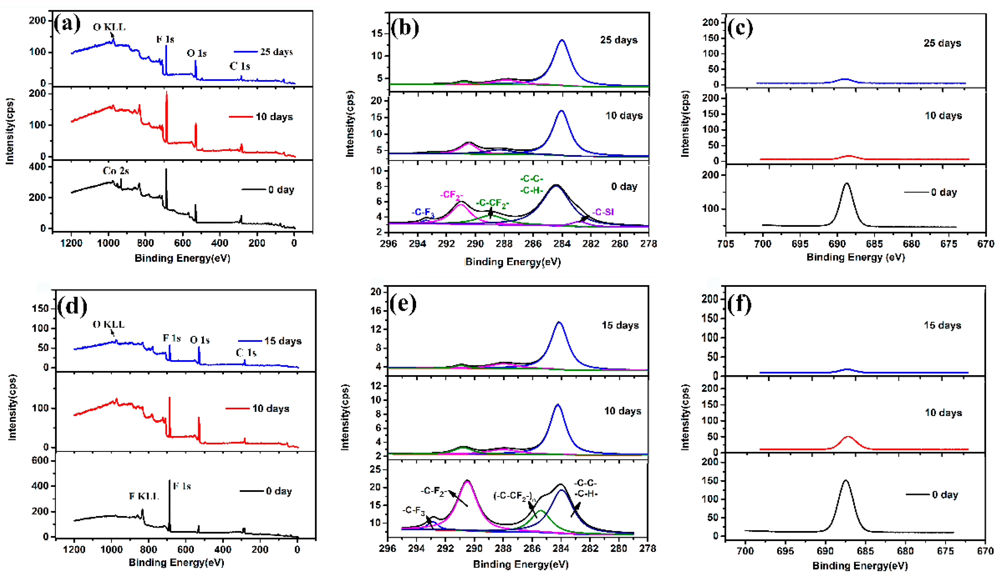
3.4. Surface Composition of Two Super-Hydrophobic Coatings with Immersion Time
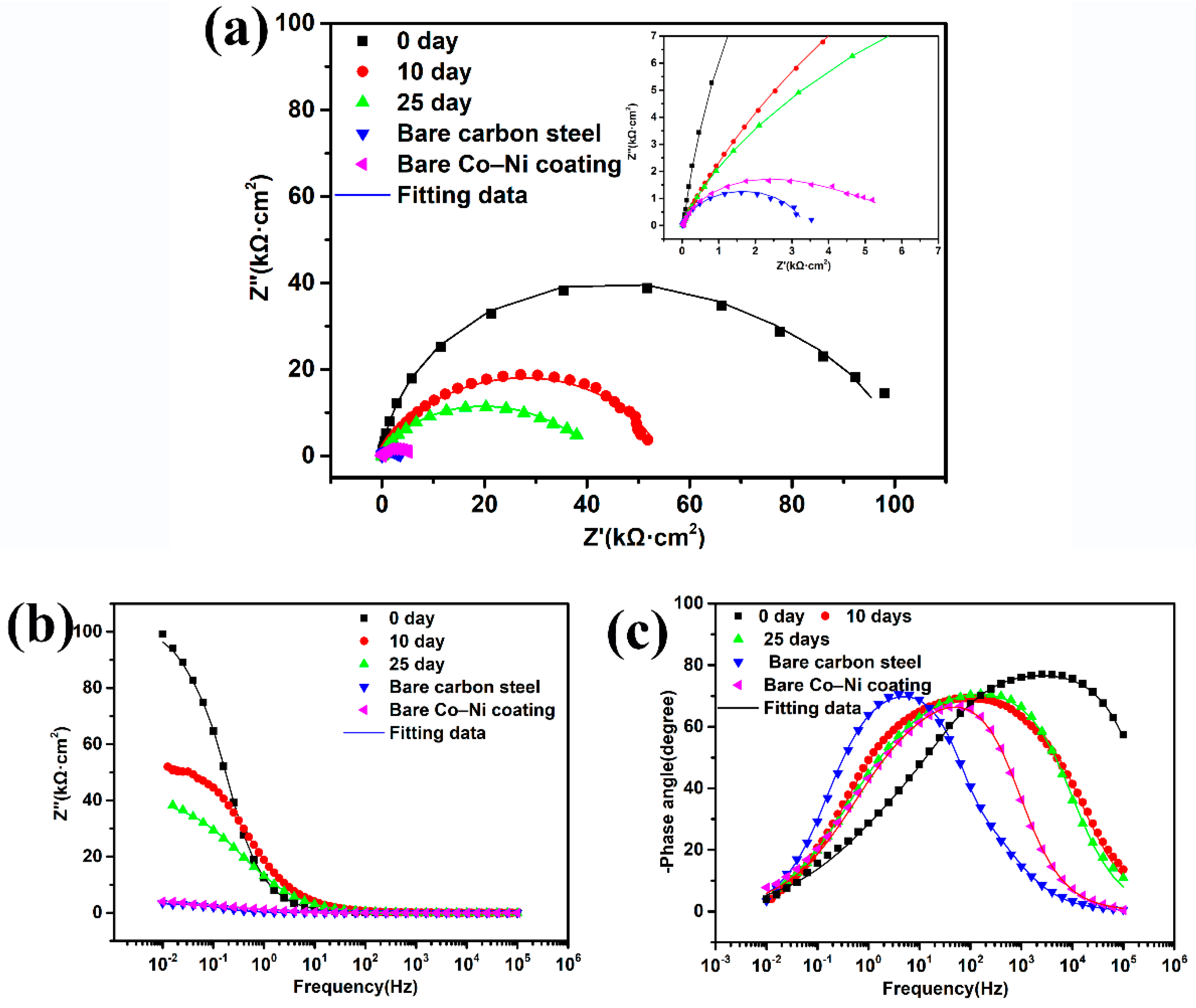
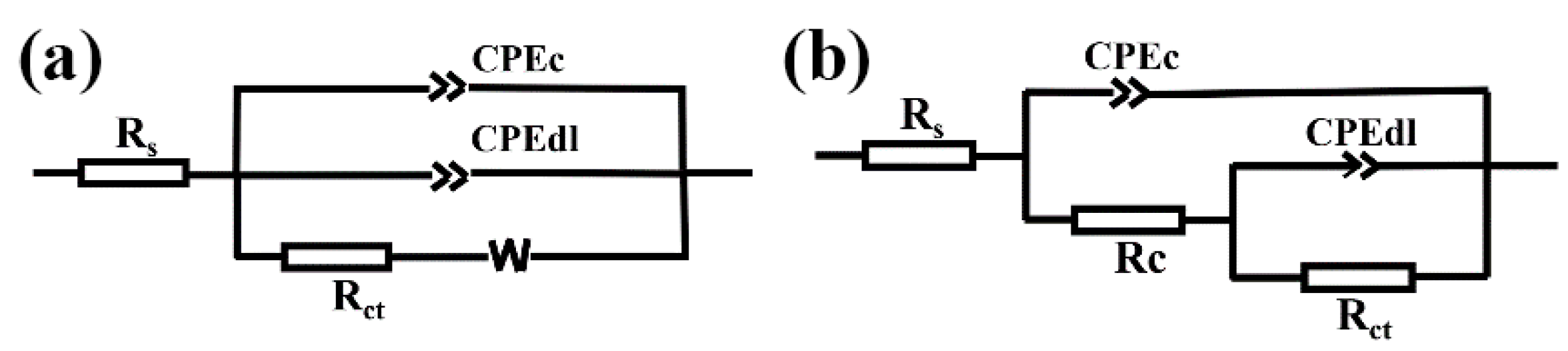
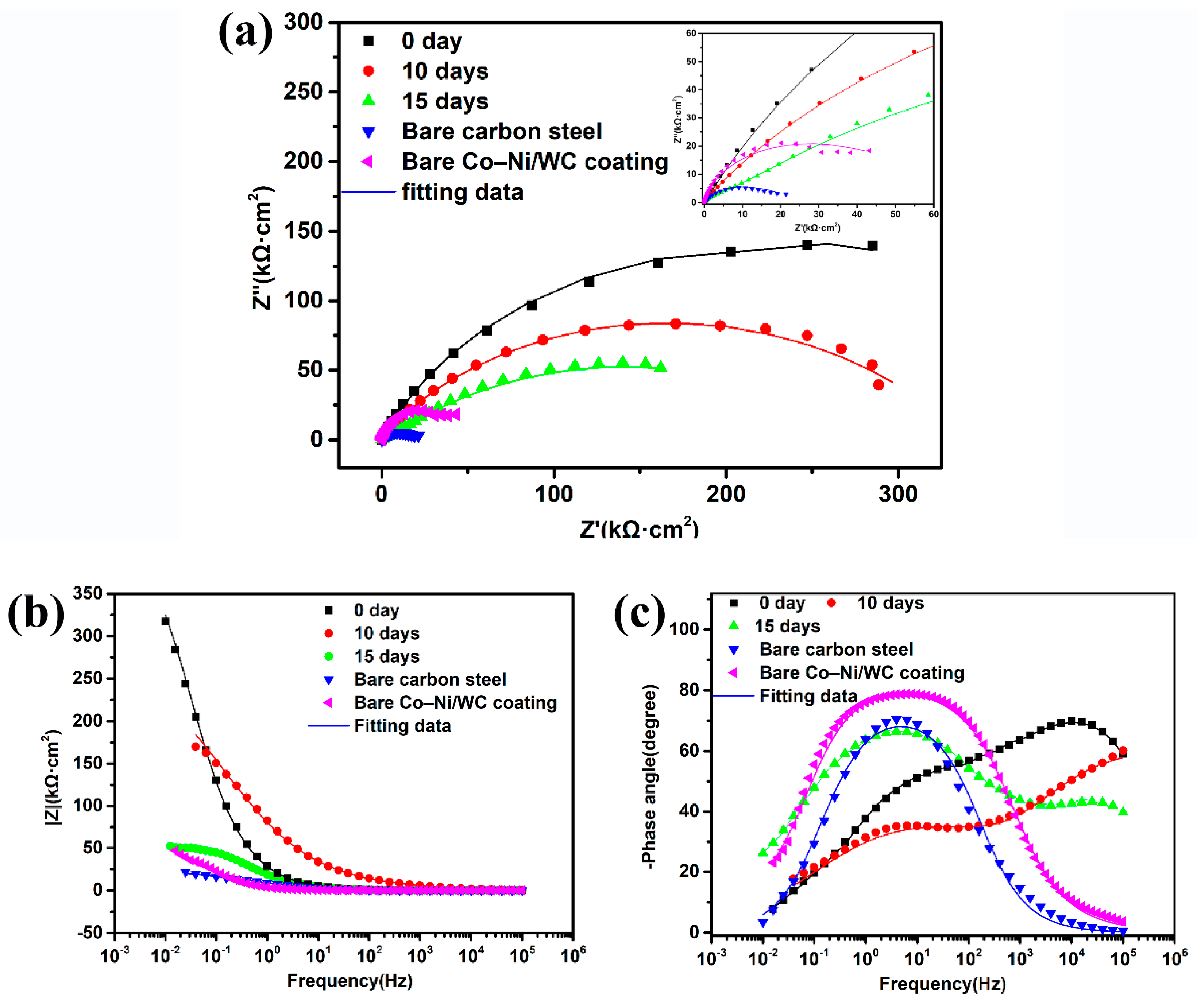
3.5. Corrosion Resistance of Two Super-Hydrophobic Coatings with Immersion Time
4. Conclusions
Author Contributions
Funding
Institutional Review Board Statement
Informed Consent Statement
Data Availability Statement
Acknowledgments
Conflicts of Interest
References
- Vazirinasab, E.; Jafari, R.; Momen, G. Application of superhydrophobic coatings as a corrosion barrier: A review. Surf. Coatings Technol. 2018, 341, 40–56. [Google Scholar] [CrossRef]
- Zhang, D.; Wang, L.; Qian, H.; Li, X. Superhydrophobic surfaces for corrosion protection: A review of recent progresses and future directions. J. Coatings Technol. Res. 2016, 13, 11–29. [Google Scholar] [CrossRef] [Green Version]
- Ruan, M.; Li, W.; Wang, B.; Deng, B.; Ma, F.; Yu, Z. Preparation and anti-icing behavior of superhydrophobic surfaces on aluminum alloy substrates. Langmuir 2013, 29, 8482–8491. [Google Scholar] [CrossRef] [PubMed]
- Liao, R.; Zuo, Z.; Guo, C.; Yuan, Y.; Zhuang, A. Fabrication of superhydrophobic surface on aluminum by continuous chemical etching and its anti-icing property. Appl. Surf. Sci. 2014, 317, 701–709. [Google Scholar] [CrossRef]
- Ge, M.; Cao, C.; Huang, J.; Zhang, X.; Tang, Y.; Zhou, X.; Zhang, K.; Chen, Z.; Lai, Y. Rational design of materials interface at nanoscale towards intelligent oil-water separation. Nanoscale Horiz. 2018, 3, 235–260. [Google Scholar] [CrossRef]
- Ma, Q.; Cheng, H.; Fane, A.G.; Wang, R.; Zhang, H. Recent development of advanced materials with special wettability for selective oil/water separation. Small 2016, 12, 2186–2202. [Google Scholar] [CrossRef]
- Dong, H.; Cheng, M.; Zhang, Y.; Wei, H.; Shi, F. Extraordinary drag-reducing effect of a superhydrophobic coating on a macroscopic model ship at high speed. J. Mater. Chem. A 2013, 1, 5886–5891. [Google Scholar] [CrossRef]
- Liu, K.; Jiang, L. Metallic surfaces with special wettability. Nanoscale 2011, 3, 825–838. [Google Scholar] [CrossRef]
- Ma, N.; Chen, Y.; Zhao, S.; Li, J.; Shan, B.; Sun, J. Preparation of super-hydrophobic surface on Al–Mg alloy substrate by electrochemical etching. Surf. Eng. 2019, 35, 394–402. [Google Scholar] [CrossRef]
- Long, J.; Fan, P.; Gong, D.; Jiang, D.; Zhang, H.; Li, L.; Zhong, M. Superhydrophobic surfaces fabricated by femtosecond laser with tunable water adhesion: From lotus leaf to rose petal. ACS Appl. Mater. Interfaces 2015, 7, 9858–9865. [Google Scholar] [CrossRef]
- Boinovich, L.B.; Modin, E.B.; Sayfutdinova, A.R.; Emelyanenko, K.A.; Vasiliev, A.L.; Emelyanenko, A.M. Combination of functional nanoengineering and nanosecond laser texturing for design of superhydrophobic aluminum alloy with exceptional mechanical and chemical properties. ACS Nano 2017, 11, 10113–10123. [Google Scholar] [CrossRef] [PubMed]
- Yu, J.; Qin, L.; Hao, Y.; Kuang, S.; Bai, X.; Chong, Y.M.; Zhang, W.; Wang, E. Vertically aligned boron nitride nanosheets: Chemical vapor synthesis, ultraviolet light emission, and superhydrophobicity. ACS Nano 2010, 4, 414–422. [Google Scholar] [CrossRef] [PubMed]
- Yanpeng, X.; Taleb, A.; Jegou, P. Electrodeposition of cobalt films with an oriented fir tree-like morphology with adjustable wetting properties using a self-assembled gold nanoparticle modified HOPG electrode. J. Mater. Chem. A 2013, 1, 11580–11588. [Google Scholar] [CrossRef]
- Xue, Y.; Wang, S.; Zhao, G.; Taleb, A.; Jin, Y. Fabrication of Ni–Co coating by electrochemical deposition with high super-hydrophobic properties for corrosion protection. Surf. Coatings Technol. 2019, 363, 352–361. [Google Scholar] [CrossRef]
- Lee, M.; Kwak, G.; Yong, K. Wettability control of ZnO nanoparticles for universal applications. ACS Appl. Mater. Interfaces 2011, 3, 3350–3356. [Google Scholar] [CrossRef] [PubMed]
- Darmanin, T.; De Givenchy, E.T.; Amigoni, S.; Guittard, F. Superhydrophobic surfaces by electrochemical processes. Adv. Mater. 2013, 25, 1378–1394. [Google Scholar] [CrossRef] [PubMed]
- Tam, J.; Palumbo, G.; Erb, U. Recent advances in superhydrophobic electrodeposits. Materials 2016, 9, 151. [Google Scholar] [CrossRef] [PubMed] [Green Version]
- Lu, Y.; Sathasivam, S.; Song, J.; Crick, C.R.; Carmalt, C.J.; Parkin, I.P. Robust self-cleaning surfaces that function when exposed to either air or oil. Science 2015, 347, 1132–1135. [Google Scholar] [CrossRef]
- Tian, X.; Verho, T.; Ras, R.H.A. Moving superhydrophobic surfaces toward real-world applications. Science 2016, 352, 142–143. [Google Scholar] [CrossRef]
- Zou, Y.; Wang, Y.; Xu, S.; Jin, T.; Wei, D.; Ouyang, J.; Jia, D.; Zhou, Y. Superhydrophobic double-layer coating for efficient heat dissipation and corrosion protection. Chem. Eng. J. 2019, 362, 638–649. [Google Scholar] [CrossRef]
- Xue, Y.; Wang, S.; Bi, P.; Zhao, G.; Jin, Y. Super-hydrophobic Co-Ni coating with high abrasion resistance prepared by electrodeposition. Coatings 2019, 9, 232. [Google Scholar] [CrossRef] [Green Version]
- Xue, Y.; Wang, S.; Xue, Y.; Cao, L.; Nie, M.; Jin, Y. Robust self-cleaning and marine anticorrosion super-hydrophobic Co–Ni/CeO2 Composite Coatings. Adv. Eng. Mater. 2020, 22, 2000402. [Google Scholar] [CrossRef]
- Tam, J.; Jiao, Z.; Lau, J.C.F.; Erb, U. Wear stability of superhydrophobic nano Ni-PTFE electrodeposits. Wear 2017, 374, 1–4. [Google Scholar] [CrossRef]
- Pezzato, L.; Vranescu, D.; Sinico, M.; Gennari, C.; Settimi, A.G.; Pranovi, P.; Brunelli, K.; Dabalà, M. Tribocorrosion properties of PEO Coatings produced on AZ91 magnesium alloy with silicate- or phosphate-based electrolytes. Coatings 2018, 8, 202. [Google Scholar] [CrossRef] [Green Version]
- Yu, N.; Xiao, X.; Ye, Z.; Pan, G. Facile preparation of durable superhydrophobic coating with self-cleaning property. Surf. Coatings Technol. 2018, 347, 199–208. [Google Scholar] [CrossRef]
- Su, F.; Yao, K. Facile fabrication of superhydrophobic surface with excellent mechanical abrasion and corrosion resistance on copper substrate by a novel method. ACS Appl. Mater. Interfaces 2014, 6, 8762–8770. [Google Scholar] [CrossRef]
- Vanithakumari, S.C.; George, R.P.; Kamachi Mudali, U. environmental stability and long-term durability of superhydrophobic coatings on titanium. J. Mater. Eng. Perform. 2017, 26, 2640–2648. [Google Scholar] [CrossRef]
- Wang, P.; Li, T.; Zhang, D. Fabrication of non-wetting surfaces on zinc surface as corrosion barrier. Corros. Sci. 2017, 128, 110–119. [Google Scholar] [CrossRef]
- Society, T.R. Hydrogen overvoltage and the reversible hydrogen electrode. Proc. R. Soc. London. Ser. A Math. Phys. Sci. 1936, 157, 423–433. [Google Scholar] [CrossRef]
- Bockris, J.O.M.; Reddy, A.K.N. Modern Electrochemistry; Plenum Press: New York, NY, USA, 1977; Volume 2, p. 883. [Google Scholar]
- Tafel, J. Über die Polarisation bei kathodischer Wasserstoffentwicklung. Z. Für Phys. Chem. 1905, 50, 641–712. [Google Scholar] [CrossRef]
- Mazare, A.; Totea, G.; Burnei, C.; Schmuki, P.; Demetrescu, I.; Ionita, D. Corrosion, antibacterial activity and haemocompatibility of TiO2 nanotubes as a function of their annealing temperature. Corros. Sci. 2016, 103, 215–222. [Google Scholar] [CrossRef]
- Kear, G.; Walsh, F.C. The characteristics of a true Tafel slope. Corros. Mater. 2005, 30, 51–55. [Google Scholar]
- Burstein, G.T. A hundred years of Tafel’s Equation: 1905–2005. Corros. Sci. 2005, 47, 2858–2870. [Google Scholar] [CrossRef]
- Zhang, X.L.; Jiang, Z.H.; Yao, Z.P.; Song, Y.; Wu, Z.D. Effects of scan rate on the potentiodynamic polarization curve obtained to determine the Tafel slopes and corrosion current density. Corros. Sci. 2009, 51, 581–587. [Google Scholar] [CrossRef]
- McCafferty, E. Validation of corrosion rates measured by the Tafel extrapolation method. Corros. Sci. 2005, 47, 3202–3215. [Google Scholar] [CrossRef]
- Wang, S.; Xue, Y.; Ban, C.; Xue, Y.; Taleb, A.; Jin, Y. Fabrication of robust tungsten carbide particles reinforced Co–Ni super-hydrophobic composite coating by electrochemical deposition. Surf. Coatings Technol. 2020, 385, 125390. [Google Scholar] [CrossRef]
- Yao, Z.; Jiang, Z.; Xin, S.; Sun, X.; Wu, X. Electrochemical impedance spectroscopy of ceramic coatings on Ti-6Al-4V by micro-plasma oxidation. Electrochim. Acta 2005, 50, 3273–3279. [Google Scholar] [CrossRef]
- Zhang, B.; Li, J.; Zhao, X.; Hu, X.; Yang, L.; Wang, N.; Li, Y.; Hou, B. Biomimetic one step fabrication of manganese stearate superhydrophobic surface as an efficient barrier against marine corrosion and Chlorella vulgaris-induced biofouling. Chem. Eng. J. 2016, 306, 441–451. [Google Scholar] [CrossRef]
- Zhang, B.; Zhu, Q.; Li, Y.; Hou, B. Facile fluorine-free one step fabrication of superhydrophobic aluminum surface towards self-cleaning and marine anticorrosion. Chem. Eng. J. 2018, 352, 625–633. [Google Scholar] [CrossRef]


| Co–Ni Coating | Co (wt.%) | Ni (wt.%) | O (wt.%) | Fe (wt.%) |
|---|---|---|---|---|
| Immersion for 0 days | 78.2 | 21.8 | - | - |
| Immersion for 10 days | 83.3 | 13.5 | 1.7 | 1.5 |
| Immersion for 25 days | 85.1 | 11.2 | 1.9 | 1.8 |
| Co–Ni Coating | Co (wt.%) | Ni (wt.%) | O (wt.%) | Fe (wt.%) | WC (wt.%) |
|---|---|---|---|---|---|
| Immersion for 0 days | 69.0 | 21.2 | - | - | 9.8 |
| Immersion for 10 days | 48.6 | 12.0 | 8.6 | 26.4 | 4.4 |
| Immersion for 25 days | 41.0 | 8.2 | 11.1 | 36.4 | 3.3 |
| Sample | Ecorr (mV) | jcorr (μA/cm2) | ba (mV·dec−1) | −bc (mV·dec−1) |
|---|---|---|---|---|
| Bare carbon steel | −459.4 ± 5.5 | 14.5 ± 0.5 | 156 ± 6.5 | 206 ± 7 |
| Immersion for 25 days | −401.4 ± 6.1 | 5.06 ± 0.4 | 78 ± 7.1 | 98 ± 2.1 |
| SHPB Co–Ni coating | −286.3 ± 5.2 | 0.629 ± 0.06 | 73 ± 4.4 | 75 ± 4.3 |
| Sample | Ecorr (mV) | jcorr (μA/cm2) | ba (mV·dec−1) | −bc (mV·dec−1) |
|---|---|---|---|---|
| Bare carbon steel | −459.4 ± 5.5 | 14.5 ± 0.5 | 156 ± 6.5 | 206 ± 7 |
| Immersion for 15 days | −303.1 ± 3.7 | 3.06 ± 0.3 | 103 ± 4.3 | 109 ± 3.3 |
| SHPB Co–Ni/WC coating | −256.4 ± 4.2 | 0.149 ± 0.07 | 75 ± 6.7 | 69 ± 2.7 |
| Fitted parameters | RS | CPEdl | ndl | Rct | CPEc | nc | Rc | Zw | Chi-Squared |
|---|---|---|---|---|---|---|---|---|---|
| Bare carbon steel | 7.93 | 4.35 × 10⁻⁴ | 0.7144 | 1.99 | 5.47 × 10⁻⁴ | 0.7442 | 24.01 | - | 4.964 × 10⁻⁴ |
| Bare Co–Ni coating | 7.64 | 8.10 × 10⁻⁵ | 0.8534 | 2.57 | 1.94 × 10⁻⁴ | 0.5971 | - | 0.0081 | 9.358 × 10⁻⁴ |
| Immersion for 0 days | 12.93 | 1.63 × 10⁻⁶ | 0.6837 | 648 | 1.41 × 10⁻⁶ | 0.8803 | 12.2 × 10⁻³ | - | 9.957 × 10⁻⁵ |
| Immersion for 10 days | 13.63 | 9.36 × 10⁻⁶ | 0.7887 | 42.8 | 3.72 × 10⁻⁵ | 0.7270 | 11.8 × 10⁻³ | - | 6.955 × 10⁻⁴ |
| Immersion for 25 days | 11.80 | 9.75 × 10⁻⁶ | 0.8237 | 9.45 | 1.88 × 10⁻⁵ | 0.5115 | 6.13 × 10⁻³ | - | 3.991 × 10⁻⁴ |
| Fitted Parameters | RS | CPEdl | ndl | Rct | CPEc | nc | Rc | Zw | Rp | Chi-Squared |
|---|---|---|---|---|---|---|---|---|---|---|
| Bare carbon steel | 7.93 | 4.35 × 10⁻⁴ | 0.7144 | 1.99 | 5.47 × 10⁻⁴ | 0.7442 | 24.01 | - | 2.35 | 4.964 × 10⁻⁴ |
| Bare Co–Ni/WC coating | 9.08 | 2.49 × 10⁻⁵ | 0.1033 | 9.56 | 4.75 × 10⁻⁵ | 0.9262 | 0.76 × 10⁻³ | 0.003 | - | 1.241 × 10⁻³ |
| Immersion for 0 days | 12.90 | 1.67 × 10⁻⁷ | 0.6732 | 67.0 | 1.41 × 10⁻⁶ | 0.4803 | 440.08 × 10⁻³ | - | 507.08 | 2.740 × 10⁻⁴ |
| Immersion for 10 days | 14.80 | 4.86 × 10⁻⁶ | 0.6781 | 44.5 | 4.31 × 10⁻⁶ | 0.7854 | 426.23 × 10⁻³ | - | 470.73 | 1.076 × 10⁻³ |
| Immersion for 15 days | 12.93 | 2.22 × 10⁻⁵ | 0.6724 | 18.8 | 7.71 × 10⁻⁴ | 0.9715 | 3.04 × 10⁻³ | - | 21.84 | 9.949 × 10⁻⁴ |
Publisher’s Note: MDPI stays neutral with regard to jurisdictional claims in published maps and institutional affiliations. |
© 2022 by the authors. Licensee MDPI, Basel, Switzerland. This article is an open access article distributed under the terms and conditions of the Creative Commons Attribution (CC BY) license (https://creativecommons.org/licenses/by/4.0/).
Share and Cite
Wang, S.; Xue, Y.; Xue, Y.; Lv, C.; Jin, Y. Long-Term Durability of Robust Super-Hydrophobic Co–Ni-Based Coatings Produced by Electrochemical Deposition. Coatings 2022, 12, 222. https://doi.org/10.3390/coatings12020222
Wang S, Xue Y, Xue Y, Lv C, Jin Y. Long-Term Durability of Robust Super-Hydrophobic Co–Ni-Based Coatings Produced by Electrochemical Deposition. Coatings. 2022; 12(2):222. https://doi.org/10.3390/coatings12020222
Chicago/Turabian StyleWang, Shuqiang, Yanpeng Xue, Yanyan Xue, Cunjing Lv, and Ying Jin. 2022. "Long-Term Durability of Robust Super-Hydrophobic Co–Ni-Based Coatings Produced by Electrochemical Deposition" Coatings 12, no. 2: 222. https://doi.org/10.3390/coatings12020222
APA StyleWang, S., Xue, Y., Xue, Y., Lv, C., & Jin, Y. (2022). Long-Term Durability of Robust Super-Hydrophobic Co–Ni-Based Coatings Produced by Electrochemical Deposition. Coatings, 12(2), 222. https://doi.org/10.3390/coatings12020222