Article

Preparation, Microstructure and Thermal Conductivity of Plasma-Sprayed (Y0.8Gd0.2)3Al5O12 Coatings

1
School of Materials Science and Engineering, Beihang University, No. 37 Xueyuan Road, Beijing 100191, China
2
Surface Engineering Research Institute, Chinese Academy of Agricultural Mechanization Sciences, No. 1 Beishatan Road, Beijing 100083, China
3
Research Institute of Frontier Science, Beihang University, No. 37 Xueyuan Road, Beijing 100191, China
4
Key Laboratory of High-Temperature Structural Materials and Coatings Technology (Ministry of Industry and Information Technology), Beihang University, No. 37 Xueyuan Road, Beijing 100191, China
5
Research Center of Modern Surface and Interface Engineering, Anhui University of Technology, Maanshan 243002, China
*
Authors to whom correspondence should be addressed.
Coatings 2022, 12(4), 510; https://doi.org/10.3390/coatings12040510
Submission received: 3 December 2021 / Revised: 17 March 2022 / Accepted: 18 March 2022 / Published: 9 April 2022

Abstract

:
Garnet-type rare earth aluminate compounds are one class of promising potential candidate materials for thermal barrier coatings (TBCs). In this paper, (Y0.8Gd0.2)3Al5O12 (GYAG) coatings are fabricated by air plasma spraying, with the microstructure, high-temperature phase stability, and thermal conductivity investigated. The results showed that the as-deposited GYAG coating was relatively dense, and contained garnet-type (Y0.8Gd0.2)3Al5O12 phase and a small amount of (Y,Gd)AlO3 and amorphous phases. The crystallized GYAG coating exhibited good phase stability from room temperature to 1450 °C. The coating had the lowest thermal conductivity of 1.17 W·m−1·K−1 at 800 °C, approximately 15% lower than that of the yttria-stabilized zirconia (YSZ) coating. After heat treatment at 1100 °C, the coating became denser with some fine grain precipitation, and formed a number of transverse and longitudinal cracks.

1. Introduction

The use of thermal barrier coatings (TBCs) can not only enhance the turbine inlet temperature, but also improve the oxidation corrosion resistance and service life of hot components [1,2,3,4,5,6,7,8]. In this way, the fuel efficiency and the thrust–weight ratio of aero engines are also increased. Currently, double layer structure (6~8 wt.%) yttria partially stabilized zirconia (YSZ)/MCrAlY (M = Ni, Co or Ni + Co) TBCs are successfully and widely applied in the gas-turbine field [2,3,4,5,9,10,11,12]. When the long-term service temperature of YSZ TBCs is above 1200 °C, the phase transformation of metastable tetragonal phase (t′ phase) to monoclinal phase (m phase) and sintering phenomenon occurs, accompanied by volumetric expansion and the deterioration of the thermo-mechanical properties [3,4,5,13]. Additionally, because YSZ is an oxygen ion conductor, oxygen can reach the bond coat through the YSZ coating at high temperatures, causing severe oxidation of the bond coat [11,12,14,15], that is, thermal growth oxide can rapidly develop. These unfavorable factors lead to the formation of stress concentration and cracks, and eventually accelerate the failure of TBCs. Therefore, YSZ cannot fulfill the requirements for the higher operating temperatures, which has promoted a pressing search for new ceramic TBCs with excellent thermodynamic performance to satisfy the needs of advanced gas turbines.
Although multiple rare earth (RE) oxide-doped YSZ and RE2(ZrCe)2O7 are promising potential TBC candidates, they have more oxygen vacancies than YSZ, thereby quickening the oxygen diffusion at high temperatures. Vaßen et al. and Guo et al. found that one of the main reasons for Gd2Zr2O7/YSZ or La2Ce2O7/YSZ TBCs failure was that the thermal growth oxide layer grew rapidly [16,17]. Among other new TBC candidate ceramics, garnet-type RE aluminate compounds, especially yttrium aluminum garnet (Y3Al5O12), have been verified as potential ceramic TBC materials due to some excellent properties [2,3,18,19]. The crystal structure of garnet-type Y3Al5O12 is composed of [AlO4] tetrahedron, [AlO6] octahedron and [YO8] dodecahedron. This compact crystal structure determines these noteworthy properties, such as excellent high-temperature mechanical properties, good high-temperature phase stability up to the melting point and extremely low oxygen transmittance that is approximately 10 orders of magnitude lower than that in YSZ [2,18,19,20,21]. Furthermore, Su et al. showed that Y3Al5O12 could obviously improve the phase stability of tetragonal-zircania and the oxidation resistance of NiCoCrAlY/YSZ TBCs at high temperatures [22]. Weyant et al. and Ravi et al. investigated the influence of precursors and spraying process parameters on the microstructure of plasma-sprayed Y3Al5O12 coatings [23,24]. However, the relatively high thermal conductivity and low coefficient of thermal expansion (CTE) of Y3Al5O12 are the limitations for its further application. According to the literature [25,26], Yb2O3 doping has the reduced thermal conductivity of Y3Al5O12, but this has little effect on the CTE.
In our previous study [27], we found that Gd2O3-modified Y3Al5O12 ceramics reveal much improved properties for TBC applications, and the composition of (Y0.8Gd0.2)3Al5O12 exhibit the best properties, such as low thermal conductivity (1.51 W·m−1·K−1, 1200 °C), high average CTE (9.8 × 10⁻⁶ K−1, 20~1200 °C) and good high-temperature phase stability from room temperature to 1600 °C. However, how Gd2O3-modified Y3Al5O12 coatings behave has not been reported. In this study, we select the optimized composition of (Y0.8Gd0.2)3Al5O12 to produce TBCs through the air plasma spraying (APS) technique, and investigate their microstructure, high-temperature phase stability and thermal conductivity. Additionally, the effects of heat treatment on the microstructure of (Y0.8Gd0.2)3Al5O12 coatings are discussed. Furthermore, the investigation will provide the theoretical and experimental basis for the structure design, preparation and high-temperature service performances of TBCs including (Y0.8Gd0.2)3Al5O12.

2. Experimental

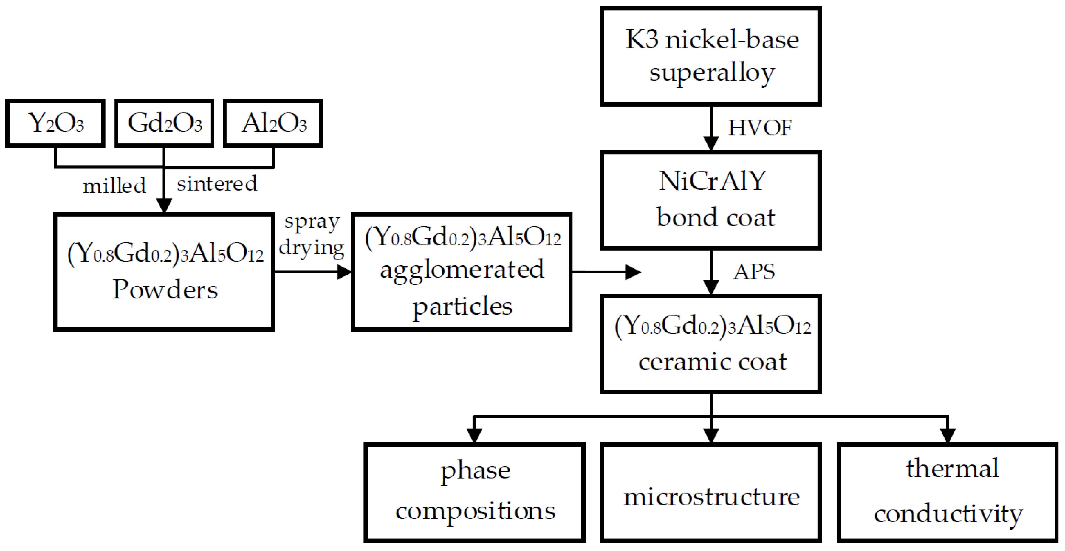
2.1. Preparation of (Y0.8Gd0.2)3Al5O12 Coating

Figure 1 shows the schematic diagram of the sample fabrication steps. (Y0.8Gd0.2)3Al5O12 powders were synthesized through a solid-state reaction method. Y2O3, Gd2O3 and Al2O3 powders (purity higher than 99.99%) were used as raw materials, which were calcined at 1000 °C for 4 h to remove adsorptive water and carbon dioxide before weighing. The appropriate amounts of individual oxides based on the stoichiometric ratio of (Y0.8Gd0.2)3Al5O12 were dispersed in ethanol and mechanically milled for 12 h. The acquired powders were sintered at 1500 °C for 10 h to complete the synthesis of the (Y0.8Gd0.2)3Al5O12 powders. Then, the synthesized (Y0.8Gd0.2)3Al5O12 powders were mechanically ball-milled again. Subsequently, these powders were transformed to agglomerated particles by a spray drying method for thermal spraying.
First, the NiCrAlY (75Ni-14Cr-9Al-2Y, wt.%) bond coat was deposited on K3 nickel-base superalloy by high-velocity oxygen flame ([HVOF], JP-5000, Praxair Surface Technologies Inc., Indianapolis, IN, USA). The chemical composition of K3 superalloy and the spraying parameters are listed in Table 1 and Table 2, respectively. Secondly, the (Y0.8Gd0.2)3Al5O12 (marked as GYAG) coatings were deposited on the NiCrAlY bond coat by the APS technique (ZB-80X, Zhenbang Aerospace Precision Machinery Co. Ltd., Guan, China), with the spraying processing parameters listed in Table 3. The thickness of the NiCrAlY bond coat and GYAG coatings is 50~100 μm and 200~300 μm, respectively, which does not change with the heat treatment. For the heat treatment of the GYAG coatings, the specimens were heated in a tube electric furnace at 1100 C for different times. Moreover, in order to compare the thermal conductivity of the GYAG ceramic coatings and YSZ ceramic coatings, free-standing GYAG and YSZ ceramic coatings with 1 mm thickness were prepared on a stainless steel substrate through the APS technique, with the spraying parameters listed in Table 3, and subsequently the stainless steel substrates were mechanically removed. YSZ (Beijing Jinlunkuntian Special Machinery Co. Ltd., Beijing, China) was selected as the spraying powders.

2.2. Characterization Analysis

The phase compositions of the specimens were identified by X-ray diffraction ([XRD], Rigaku Diffractometer D/max 2200PC, Cu Kα radiation λ = 0.15418 nm, Tokyo, Japan). The microstructure of the specimens was characterized by a scanning electron microscopy ([SEM], FEI, Hillsboro, OR, USA) equipped with energy dispersive spectroscopy (EDS). The chemical compositions of the powders for thermal spraying and the fabricated coating are determined by EDS. The porosity of the samples (ρ) was measured by the Archimedes method in distilled water [28,29]. The specific heat capacity (Cp) of the GYAG and YSZ ceramic coatings were calculated by the Neumann–Kopp rule from the specific heat values of their chemical compositions. The thermal diffusivity (α) of the samples with dimensions of 12.7 mm diameter and 1 mm thickness coated with a thin layer of graphite for the thermal absorption of laser pulses before measurement was collected by a laser flash device (Netzsch LFA427, Selb, Germany) from room temperature to 1200 °C. The thermal conductivities (k) of GYAG and YSZ ceramic coatings were calculated from the thermal diffusivity (α) and specific heat capacity (Cp) through Equation (1). In order to conveniently compare the thermal conductivity of the GYAG ceramic coating and YSZ ceramic coating, the thermal conductivities of the two types of coatings with porosity (k) were transformed into those of fully dense samples (k0) through Equation (2), where Φ is the fractional porosity [3,4]. The porosity of the coating could be tested through the Archimedes method [28,29], and the values for the GYAG coating and YSZ coating were about 10% and 15%, respectively.
k = ρ · α · C p  
k k 0 = 1 4 Φ 3
The differential scanning calorimetry (DSC) curves of the as-deposited and heat-treated GYAG coatings were obtained by a differential scanning calorimetry (Netzsch STA 409C/CD, Selb, Germany), with a heating rate of 10 °C/min under an argon atmosphere from room temperature to 1450 °C. The heat-treated states free-standing coatings were heated at 1250 °C for 5 h. For DSC measurements, 10 mg samples were enough, and each sample was measured twice to ensure accuracy.

3. Result and Discussion

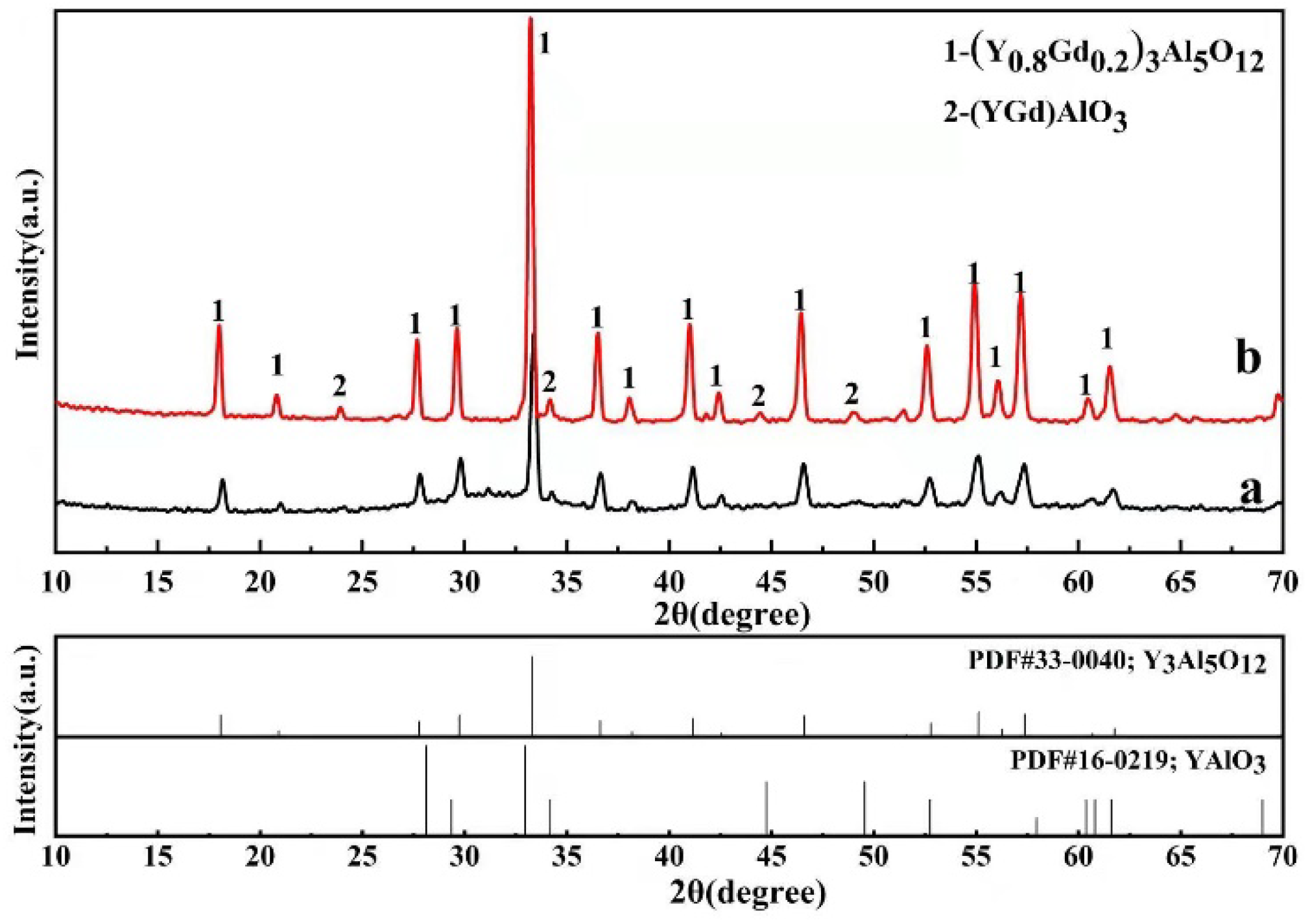
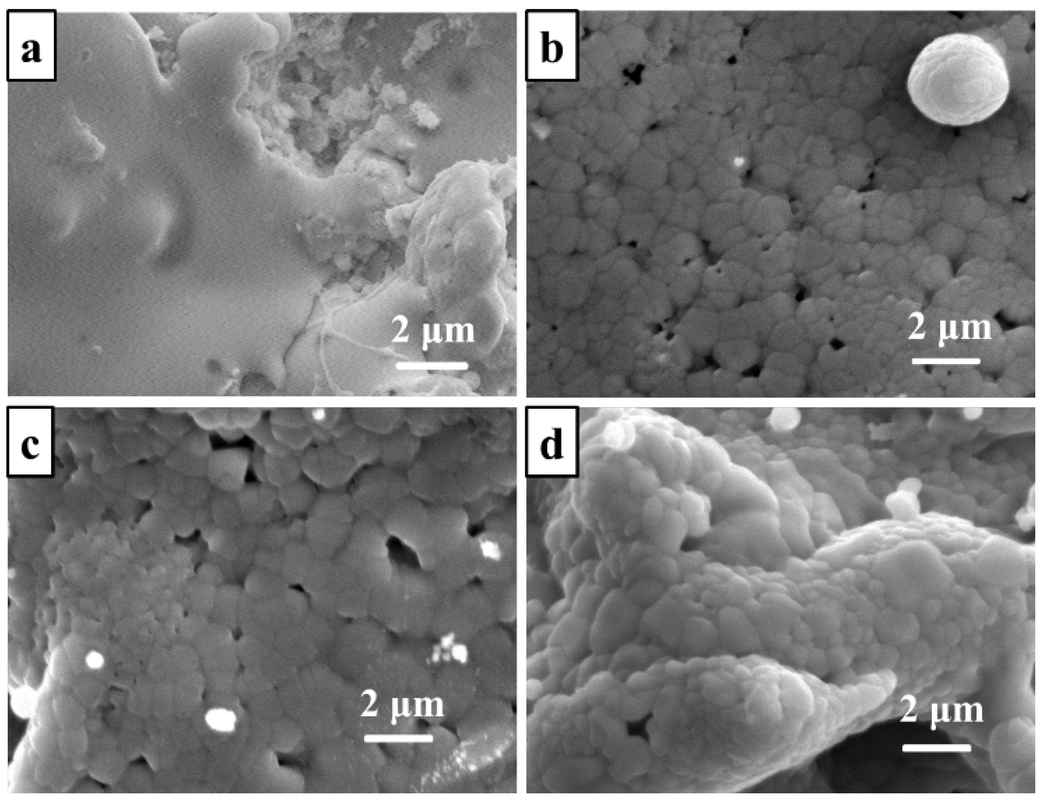
3.1. Preparation and Microstructure

It is reported that directly synthesized powders cannot be used for plasma spraying, as their liquidity and deposition efficiency are very poor [30,31]. Hence, agglomerated (Y0.8Gd0.2)3Al5O12 particles were produced to meet the needs of the plasma spraying. Figure 2 shows the SEM image of agglomerated particles. They reveal spherical and doughnut-like morphologies, both of which are suitable for thermal spraying. The particles have the average size in a range of 40~60 μm. The chemical composition of the agglomerated particles is determined by EDS, which has 4.2 at% Gd, 16.5 at% Y and 34.6 at% Al. The enlarged view of the surface of the agglomerated particles is shown in the insert image of Figure 2. It could be found that they consist of many fine particles.
Figure 3 presents the surface and cross-section SEM images of the as-deposited GYAG coating through plasma spraying. The surface morphology of the GYAG coating is non-uniform and relatively rough, and there is a small amount of porosity, as shown in Figure 3a, where the surface of the GYAG coating has two different morphological features: (I) smooth and dense morphology due to the fully melted spraying powders; and (II) loose and porous morphology, which is mainly due to the spraying powders inadequately melting in the spraying process. The GYAG coating has approximately 240 μm thickness. The coating has a lamellar microstructure, with some cracks and pores in the cross-section, as highlighted by yellow and red arrows in Figure 3b, respectively. The existence of pores and microcracks is prevailingly caused by the insufficient melting of some GYAG ceramic powders and the stress produced by the condensation of the droplets during the spraying process. The presence of microcracks and pores in the coating is one of the characteristics of plasma-sprayed coating. The chemical composition of the region highlighted by a red square in Figure 3c was determined by EDS, which has 17.7 at% Y, 4.3 at% Gd, 35.8 at% Al and 42.2 at% O. The Y/Gd ratio and (Y + Gd)/Al ratio in the coating are 4.1 and 0.61, respectively, which are close to those of (Y0.8Gd0.2)3Al5O12, suggesting that the spraying parameters used in this study are reasonable. Note that the bond coating has excellent connection with the (Y0.8Gd0.2)3Al5O12 coating and the substrate.
Figure 4 shows the XRD patterns of the GYAG feedstock and as-deposited GYAG coating. It exhibits mainly garnet (Y0.8Gd0.2)3Al5O12 phase and a small amount of (Y,Gd)AlO3 phase in the coating. Furthermore, amorphous “steamed bread” peak is presented in the XRD patterns of the as-deposited GYAG coating, which is derived from the high temperature of the plasma flame flow and large condensation rate of the spraying powders. The analysis results are ultimately consistent with those reported in the literature [23,24].

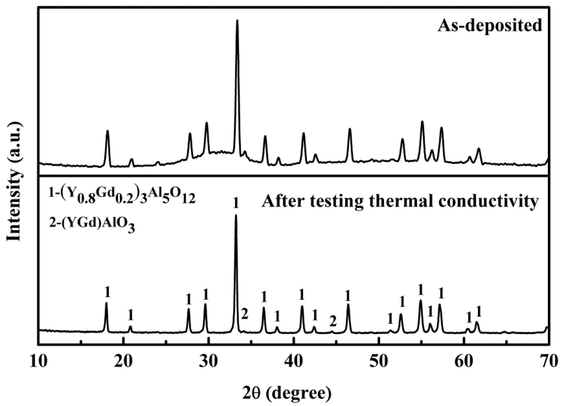
3.2. High-Temperature Phase Stability

The high-temperature phase stability of ceramic coating is one of the most important parameters for TBCs. Phase transformation or structural change may result in the failure of a TBC system [1,2,5]. Figure 5 compares the XRD patterns of the as-deposited and the heat-treated coatings at 1350 °C for 5 h. Both coatings consist of (Y0.8Gd0.2)3Al5O12 and (Y,Gd)AlO3 phases, and the amount of the latter is rather limited which could be confirmed by the low intensities of its diffraction peaks. Note that the diffraction peaks of the as-deposited coating are much broader than those of the coating after the heat treatment. This indicates that heat treatment promotes the crystallization of amorphous state. Figure 6 shows the DSC curves of the GYAG coatings before and after heat treatment. There is an obvious exothermic peak at around 850 °C in the DSC curve of the as-deposited coating. According to the DSC curve of the coating after heat treatment at 1250 °C for 5 h, there is no exothermic peak or endothermic peak indicative of no phase transformation or possible reaction. Thus, using XRD spectra to deduce the phase composition of the coating after heat treatment at 1350 °C for 5 h is reasonable. Considering the XRD results in Figure 5, the presence of the exothermic peak could be attributed to the crystallization of amorphous state. Figure 6 reveals that no exothermic peak or endothermic peak exists in the curve of the heat-treated coating, which indicates that the coating has been completely crystallized after heat treatment, and it has good phase stability when heating from room temperature to 1450 °C.

3.3. Thermal Conductivity

Since the amount of the (Y,Gd)AlO3 crystal phase is low, its influence on the thermal conductivity of the coating is rather limited. Thus, only the main phase of (Y0.8Gd0.2)3Al5O12 is considered when calculating the thermal conductivity of the coating. The specific heat capacities (Cp) of (Y0.8Gd0.2)3Al5O12 and YSZ were calculated by the Neumann–Kopp rule, as shown in Table 4.
The thermal diffusivities of the GYAG ceramic coating and YSZ ceramic coating as functions of temperature are shown in Figure 7a, respectively. The measurement uncertainty is derived from the mean standard deviation, and the error bars are much smaller than the symbols, which are not plotted for clarity. The thermal diffusivities of both the GYAG and YSZ coatings gradually decrease with the temperature rising up to 800 °C. The T−1 dependence of thermal diffusivity suggests a dominant phonon thermal behavior that is universal in polycrystalline materials [32,33]. The thermal diffusivity of the YSZ coating increases with heating from 800 to 1200 °C. Differently, the thermal diffusivity of the GYAG coating quickly increases with heating from 800 to 1000 °C, and subsequently slowly decreases with temperature up to 1200 °C. Moreover, the thermal diffusivity of the GYAG coating is very close to that of the YSZ coating from room temperature to 800 °C. However, from 800 to 1200 °C, the thermal diffusivity of the GYAG coating is higher than that of the YSZ coating. The minimum thermal diffusivities of both the GYAG and YSZ coatings are obtained at 800 °C within the test temperature range.
The thermal conductivities of the GYAG coating and YSZ coating calculated and corrected through Equations (1) and (2) are plotted in Figure 7b. The measurement uncertainty of the thermal conductivity is within the range of ±0.1 W·m−1·K−1 at each of the temperatures for each specimen, with the error bars omitted for clarity in Figure 7b. The variation tendency of thermal conductivities of the GYAG coating and YSZ coating are basically consistent with that of their thermal diffusivities. Within the test temperature range, the thermal conductivity of the GYAG coating was obviously lower than that of the YSZ coating, except at 1000 °C. The lowest thermal conductivity value of the GYAG coating was 1.17 W·m−1·K−1 at 800 °C, approximately 15% lower than that of the YSZ coating. Additionally, from 1000 to 1200 °C, the thermal conductivity of the YSZ coating increases; however, the thermal conductivity of the GYAG coating decreases with the increase in temperature.
The change in the thermal conductivity of the GYAG coating from room temperature to 1000 °C is distinct from that of the (Y0.8Gd0.2)3Al5O12 bulk ceramic reported by our previous study [27]. Firstly, compared with the bulk ceramic, the thermal conductivity of the GYAG coating becomes lower and slowly declines with temperature up to 800 °C. This phenomenon could be explained as followings. For the GYAG coating, the dominant phonon scattering conduction is caused by the phonons lattice vibrations of heat transport theory, the amorphous phase, microcracks and porosity in coating. The phonon scattering increases with the temperature. Moreover, the presence of the amorphous phase, microcracks and porosity in coating could largely enhance the phonon scattering effect. Both effects result in the decrease in thermal conductivity. Secondly, the thermal conductivity quickly increases from 800 to 1000 °C. This results from the reduced scattering effect of amorphous phase in this temperature range. The coating becomes crystallized and amorphous phases are transformed into crystalline phases with heating from 800 to 1000 °C. This can be proved by the XRD patterns of the GYAG coating before and after measuring the thermal conductivity, as shown in Figure 8. A certain amount of amorphous phase exists in the coating before testing the thermal conductivity; however, the amorphous phase disappears after the test. In other words, the crystallization of the GYAG coating becomes complete after the test. Subsequently, the thermal conductivity of the GYAG ceramic coating is around 1.45 W·m−1·K−1 at 1200 °C.

3.4. The Effect of Heat Treatment on the Microstructure

As mentioned above, the as-deposited GYAG coating contains a certain amount of amorphous phase, which is heat treated to investigate the microstructure. Figure 9 shows the surface SEM morphologies of the as-deposited GYAG coating and the coatings heat treated at 1100 °C for 2, 5 and 10 h. By comparison, it could be found that the smooth regions in the surface of the as-deposited coating transform to the regions consisting of many fine grains after heat treatment at 1100 °C. This is an indicator of heat treatment promoting the crystallization of amorphous state. Additionally, some cracks and pores are found in the surfaces of the coatings after heat treatments. The reasons for this phenomenon may be the residual stresses and amorphous transformation during the deposition process. As the heat treatment of the as-deposited coating is carried out at 1100 °C for different times, the residual stress is released and the amorphous state is transformed into a crystalline state. The surface morphology of the GYAG coating after heat treatment for 2 h is basically close to that for 5 h. The grain size is confirmed to be approximately 800 nm by the intercept method [34] after heat treatment for 10 h.
Figure 10 shows the cross-section SEM images of the GYAG coating at 1100 °C for different times. Compared with the as-deposited GYAG coating, the coating becomes much denser and has some transverse cracks and longitudinal cracks generated after the heat treatment, as seen in Figure 10. In particular, the longitudinal cracks are beneficial to increase the damage tolerance, thereby prolonging the service life of the coating [35]. However, the bottom of the GYAG coating heat treated at 1100 °C for 10 h generated serious transverse cracks. Besides the residual stress and amorphous transformation of the coating, the thermal expansion mismatch between GYAG and NiCrAlY may be the main cause of the crack propagation.
The factors that are responsible for the failure of TBCs include (1) sintering and phase transformation of the ceramic top coat, (2) oxidation of bond coat, (3) thermal expansion mismatch between bond coat and ceramic top coat and (4) the continuously changing interface structure [36]. The lifetime of TBCs is also affected by preparation process, microstructure, composition and service temperature. APS TBCs usually exhibit lamellar and porous structure (15% to 25% porosity [37]) with microcracks parallel to bond coat and top coat interface. The initiation, nucleation, propagation and connection of the cracks result in the top coat spallation and TBCs failure. In recent years, self-healing TBCs are considered [38,39,40], which are based on MoSi2, SiC and TiC healing particles that are randomly distribution in the top coat. When TBCs were endured with high temperature, cracks propagate and encounter the healing particles. The healing particles oxidation is triggered and SiO2 forms in the cracked area, which filled the gap of crack. As a result, the lifetime of TBCs could be prolonged.
Therefore, for the possible use of GYAG coatings, double ceramic-layer (DCL) TBCs could be designed, in which the GYAG coating is used as an outer ceramic layer for better thermal insulation and improved high-temperature capability, and YSZ is designed as an inner layer for reducing the thermal mismatch between the outer coating and the substrate. GYAG/YSZ DCL TBCs are considered to have improved thermal cycling durability. The design of the self-healing GYAG top coating may help to improve the ability to inhibit the crack propagation and may further increase the thermal cycling durability of the coating system. The relevant research results will be reported in our future study.
Figure 11 shows the XRD patterns of the GYAG coating after heat treatment at 1100 °C for different times. The coating has been completely crystallized after heat treatment at 1100 °C for 2 h. The heat-treated GYAG coating still mainly contains (Y0.8Gd0.2)3Al5O12 phase and a small number of (Y,Gd)AlO3 phase, with other new phases not observed. The crystal phase compositions in the coating do not change with the increase in heat treatment time.

4. Conclusions

  • The (Y0.8Gd0.2)3Al5O12 (GYAG) coating was successfully fabricated by air plasma spraying. The as-deposited GYAG coating was relatively dense, and mainly contained garnet-type (Y0.8Gd0.2)3Al5O12 phase, and a small amount of (Y,Gd)AlO3 phase and amorphous phase.
  • There was only one exothermic peak at about 850 °C existing in the as-deposited GYAG ceramic coating from room temperature to 1450 °C. The crystallized GYAG coating exhibited good phase stability in the above temperature range. The thermal conductivity of the coating slowly decreased up to 800 °C, then quickly increased from 800 to 1000 °C, and subsequently decreased from 1000 to 1200 °C. The lowest thermal conductivity value of the GYAG coating was 1.17 W·m−1·K−1 at 800 ℃, around 15% lower than that of the plasma-sprayed YSZ coating. Meanwhile, the as-deposited coating had been completely crystallized after testing the thermal conductivity.
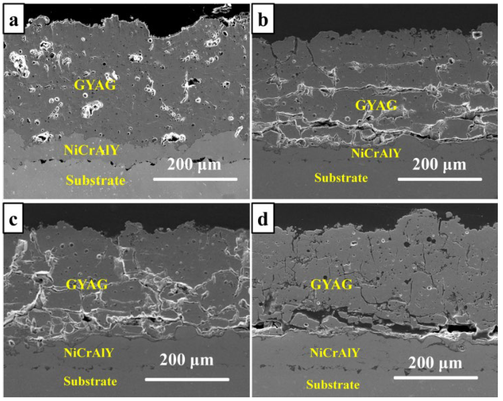
  • The heat-treated coating became denser and had some fine grains precipitated. The coating had some transverse cracks and longitudinal cracks generated after the heat treatment at 1100 °C. Serious transverse cracks were produced at the bottom of the GYAG coating due to the mismatch of thermal expansion between GYAG and NiCrAlY.

Author Contributions

Conceptualization, J.H.; data curation, S.W.; formal analysis, S.W.; funding acquisition, J.H.; methodology, Z.X.; writing—original draft, S.W.; writing—review & editing, J.H. and Z.X. All authors have read and agreed to the published version of the manuscript.

Funding

This research is sponsored by the National Natural Science Foundation of China (NFSC) under Grant Nos. 51901011 and 92060301, National Science and Technology Major Project under Grant No. 2017-VII-0007-0100 and supported by the fund of State Key Laboratory of Long-life High Temperature Materials under No. DTCC28EE200793.

Institutional Review Board Statement

Not applicable.

Informed Consent Statement

Not applicable.

Data Availability Statement

Not applicable.

Conflicts of Interest

The authors declare no conflict of interest.

References

  1. Darolia, R. Thermal Barrier Coatings Technology: Critical Review, Progress Update, Remaining Challenges and Prospects. Int. Mater. Rev. 2013, 58, 315–348. [Google Scholar] [CrossRef]
  2. Cao, X.Q.; Vassen, R.; Stoever, D. Ceramic Materials for Thermal Barrier Coatings. J. Eur. Ceram. Soc. 2004, 24, 1–10. [Google Scholar] [CrossRef]
  3. Xue, Z.; Ma, Y.; Guo, H. Synthesis, Thermal Conductivities and Phase Stability of Gd3TaO7 and La Doped Gd3TaO7 Ceramics. J. Alloys Compd. 2018, 732, 759–764. [Google Scholar] [CrossRef]
  4. Guo, L.; Guo, H.; Gong, S.; Xu, H. Improvement on the Phase Stability, Mechanical Properties and Thermal Insulation of Y2O3-Stabilized ZrO2 by Gd2O3 and Yb2O3 Co-Doping. Ceram. Int. 2013, 39, 9009–9015. [Google Scholar] [CrossRef]
  5. Vaßen, R.; Jarligo, M.O.; Steinke, T.; Mack, D.E.; Stöver, D. Overview on Advanced Thermal Barrier Coatings. Surf. Coatings Technol. 2010, 205, 938–942. [Google Scholar] [CrossRef]
  6. Liu, B.; Liu, Y.; Zhu, C.; Xiang, H.; Chen, H.; Sun, L.; Gao, Y.; Zhou, Y. Advances on Strategies for Searching for next Generation Thermal Barrier Coating Materials. J. Mater. Sci. Technol. 2019, 35, 833–851. [Google Scholar] [CrossRef]
  7. Lashmi, P.G.; Ananthapadmanabhan, P.V.; Unnikrishnan, G.; Aruna, S.T. Present Status and Future Prospects of Plasma Sprayed Multilayered Thermal Barrier Coating Systems. J. Eur. Ceram. Soc. 2020, 40, 2731–2745. [Google Scholar] [CrossRef]
  8. Thakare, J.G.; Pandey, C.; Mahapatra, M.M.; Mulik, R.S. Thermal Barrier Coatings—A State of the Art Review. Met. Mater. Int. 2021, 27, 1947–1968. [Google Scholar] [CrossRef]
  9. Zhao, Y.; Gao, Y. Structural Evolution of Plasma-Sprayed Nanoscale 3 Mol% and 5 Mol% Yttria-Stabilized Zirconia Coatings during Sintering. Appl. Surf. Sci. 2017, 425, 1033–1039. [Google Scholar] [CrossRef]
  10. Zhou, F.; Wang, Y.; Wang, Y.; Wang, L.; Gou, J.; Chen, W. A Promising Non-Transformable Tetragonal YSZ Nanostructured Feedstocks for Plasma Spraying-Physical Vapor Deposition. Ceram. Int. 2018, 44, 1201–1204. [Google Scholar] [CrossRef]
  11. Ganvir, A.; Calinas, R.F.; Markocsan, N.; Curry, N.; Joshi, S. Experimental Visualization of Microstructure Evolution during Suspension Plasma Spraying of Thermal Barrier Coatings. J. Eur. Ceram. Soc. 2019, 39, 470–481. [Google Scholar] [CrossRef]
  12. Wang, J.; Sun, J.; Zhang, H.; Dong, S.; Jiang, J.; Deng, L.; Zhou, X.; Cao, X. Effect of Spraying Power on Microstructure and Property of Nanostructured YSZ Thermal Barrier Coatings. J. Alloys Compd. 2018, 730, 471–482. [Google Scholar] [CrossRef]
  13. Shen, Y.; Leckie, R.M.; Levi, C.G.; Clarke, D.R. Low Thermal Conductivity without Oxygen Vacancies in Equimolar YO1.5 + TaO2.5- and YbO1.5 + TaO2.5-Stabilized Tetragonal Zirconia Ceramics. Acta Mater. 2010, 58, 4424–4431. [Google Scholar] [CrossRef]
  14. Masó, N.; West, A.R. Electronic Conductivity in Yttria-Stabilized Zirconia under a Small Dc Bias. Chem. Mater. 2015, 27, 1552–1558. [Google Scholar] [CrossRef]
  15. Mahato, N.; Banerjee, A.; Gupta, A.; Omar, S.; Balani, K. Progress in Material Selection for Solid Oxide Fuel Cell Technology: A Review. Prog. Mater. Sci. 2015, 72, 141–337. [Google Scholar] [CrossRef]
  16. Vaßen, R.; Traeger, F.; Stöver, D. New Thermal Barrier Coatings Based on Pyrochlore/YSZ Double-Layer Systems. Int. J. Appl. Ceram. Technol. 2005, 1, 351–361. [Google Scholar] [CrossRef]
  17. Guo, H.; Wang, Y.; Wang, L.; Gong, S. Thermo-Physical Properties and Thermal Shock Resistance of Segmented La2Ce2O7/YSZ Thermal Barrier Coatings. J. Therm. Spray Technol. 2009, 18, 665–671. [Google Scholar] [CrossRef]
  18. Padture, N.P.; Klemens, P.G. Low Thermal Conductivity in Garnets. J. Am. Ceram. Soc. 1997, 80, 1018–1020. [Google Scholar] [CrossRef]
  19. Zhou, Y.; Xiang, H.; Feng, Z. Theoretical Investigation on Mechanical and Thermal Properties of a Promising Thermal Barrier Material: Yb3Al5O12. J. Mater. Sci. Technol. 2014, 30, 631–638. [Google Scholar] [CrossRef]
  20. Parthasarathy, T.A.; Mah, T.-I.; Keller, K. Creep Mechanism of Polycrystalline Yttrium Aluminum Garnet. J. Am. Ceram. Soc. 1992, 75, 1756–1759. [Google Scholar] [CrossRef]
  21. Li, J.Y.; Dai, H.; Zhong, X.H.; Zhang, Y.F.; Ma, X.F.; Meng, J.; Cao, X.Q. Effect of the Addition of YAG (Y3Al5O12) Nanopowder on the Mechanical Properties of Lanthanum Zirconate. Mater. Sci. Eng. A 2007, 460–461, 504–508. [Google Scholar] [CrossRef]
  22. Su, Y.J.; Trice, R.W.; Faber, K.T.; Wang, H.; Porter, W.D. Thermal Conductivity, Phase Stability, and Oxidation Resistance of Y3Al5O12 (YAG)/Y2O3–ZrO2 (YSZ) Thermal-Barrier Coatings. Oxid. Met. 2004, 61, 253–271. [Google Scholar] [CrossRef]
  23. Weyant, C.M.; Faber, K.T. Processing-Microstructure Relationships for Plasma-Sprayed Yttrium Aluminum Garnet. Surf. Coatings Technol. 2008, 202, 6081–6089. [Google Scholar] [CrossRef]
  24. Ravi, B.G.; Gandhi, A.S.; Guo, X.Z.; Margolies, J.; Sampath, S. Liquid Precursor Plasma Spraying of Functional Materials: A Case Study for Yttrium Aluminum Garnet (YAG). J. Therm. Spray Technol. 2008, 17, 82–90. [Google Scholar] [CrossRef]
  25. Wang, J.; Xu, F.; Wheatley, R.J.; Neate, N.; Hou, X. Yb3+ Doping Effects on Thermal Conductivity and Thermal Expansion of Yttrium Aluminium Garnet. Ceram. Int. 2016, 42, 14228–14235. [Google Scholar] [CrossRef]
  26. Xue, Z.; Ma, Y.; Gong, S.; Guo, H. Influence of Yb3+ Doping on Phase Stability and Thermophysical Properties of (Y1-XYbx)3Al5O12 under High Temperature. Ceram. Int. 2017, 43, 7153–7158. [Google Scholar] [CrossRef]
  27. Xue, Z.; Ma, Y.; Guo, H. The Influence of Gd Doping on Thermophysical Properties, Elasticity Modulus and Phase Stability of Garnet-Type (Y1-XGdx)3Al5O12 Ceramics. J. Eur. Ceram. Soc. 2017, 37, 4171–4177. [Google Scholar] [CrossRef]
  28. Ilavsky, J.; Allen, A.J.; Long, G.G.; Krueger, S.; Berndt, C.C.; Herman, H. Influence of Spray Angle on the Pore and Crack Microstructure of Plasma-Sprayed Deposits. J. Am. Ceram. Soc. 1997, 80, 733–742. [Google Scholar] [CrossRef]
  29. ASTM International ASTM C373-17; Standard Test Methods for Determination of Water Absorption and Associated Properties by Vacuum Method for Pressed Ceramic Tiles and Glass Tiles and Boil Method for Extruded Ceramic Tiles and Non-Tile Fired Ceramic Whiteware Products. ASTM International: West Conshohocken, PA, USA, 2016.
  30. Cao, X.Q.; Vassen, R.; Schwartz, S.; Jungen, W.; Tietz, F.; Stöever, D. Spray-Drying of Ceramics for Plasma-Spray Coating. J. Eur. Ceram. Soc. 2000, 20, 2433–2439. [Google Scholar] [CrossRef]
  31. Loghman-Estarki, M.R.; Edris, H.; Razavi, R.S.; Jamali, H.; Ghasemi, R.; Pourbafrany, M.; Erfanmanesh, M.; Ramezani, M. Spray Drying of Nanometric SYSZ Powders to Obtain Plasma Sprayable Nanostructured Granules. Ceram. Int. 2013, 39, 9447–9457. [Google Scholar] [CrossRef]
  32. Wan, C.; Qu, Z.; Du, A.; Pan, W. Influence of B Site Substituent Ti on the Structure and Thermophysical Properties of A2B2O7-Type Pyrochlore Gd2Zr2O7. Acta Mater. 2009, 57, 4782–4789. [Google Scholar] [CrossRef]
  33. Haoming, Z.; Yan, F.; Xiaoge, C.; Hongsong, Z.; Yanxu, L.; An, T.; Bo, R. Thermal Properties of La3TaO7 and La2AlTaO7 Oxides. Ceram. Int. 2017, 43, 755–759. [Google Scholar] [CrossRef]
  34. Abrams, H. Grain Size Measurement by the Intercept Method. Metallography 1971, 4, 59–78. [Google Scholar] [CrossRef]
  35. Guo, H.B.; Murakami, H.; Kuroda, S. Effect of Hollow Spherical Powder Size Distribution on Porosity and Segmentation Cracks in Thermal Barrier Coatings. J. Am. Ceram. Soc. 2006, 89, 3797–3804. [Google Scholar] [CrossRef]
  36. Dehkharghani, A.M.F.; Rahimipour, M.R.; Zakeri, M. Improving the Thermal Shock Resistance and Fracture Toughness of Synthesized La2Ce2O7 Thermal Barrier Coatings through Formation of La2Ce2O7/YSZ Composite Coating via Air Plasma Spraying. Surf. Coatings Technol. 2020, 399, 126174. [Google Scholar] [CrossRef]
  37. Padture, N.P.; Gell, M.; Jordan, E.H. Thermal Barrier Coatings for Gas-Turbine Engine Applications. Science 2002, 296, 280–284. [Google Scholar] [CrossRef]
  38. Krishnasamy, J.; Ponnusami, S.A.; Turteltaub, S.; van der Zwaag, S. Thermal Cyclic Behavior and Lifetime Prediction of Self-Healing Thermal Barrier Coatings. Int. J. Solids Struct. 2021, 222–223, 111034. [Google Scholar] [CrossRef]
  39. Wang, L.; Ming, C.; Zhong, X.H.; Ni, J.X.; Yang, J.S.; Tao, S.Y.; Zhou, F.F.; Wang, Y. Microstructure and Self-Healing Properties of Multi-Layered NiCoCrAlY/TAZ/YSZ Thermal Barrier Coatings Fabricated by Atmospheric Plasma Spraying. Appl. Surf. Sci. 2019, 488, 246–260. [Google Scholar] [CrossRef]
  40. Ouyang, T.; Suo, J. TiC-Self-Healing Thermal Barrier Coating Structures and Oxidation Resistance. Surf. Coatings Technol. 2021, 412, 127065. [Google Scholar] [CrossRef]
Figure 1. Schematic diagram of the sample fabrication steps.
Coatings 12 00510 g001
Figure 2. SEM images of (Y0.8Gd0.2)3Al5O12 (a) and NiCrAlY (b) powders for spraying.
Coatings 12 00510 g002
Figure 3. Surface (a,b) and cross-section (c,d) SEM images of plasma-sprayed GYAG coating, the porosities and cracks are highlighted by yellow and red arrows, respectively.
Coatings 12 00510 g003
Figure 4. XRD patterns of the as-deposited GYAG coatings (a) and GYAG feedstock (b).
Coatings 12 00510 g004
Figure 5. XRD patterns of GYAG coatings before and after heat treatment: (a) as-deposited state; (b) heat-treated state at 1350 °C for 5 h.
Coatings 12 00510 g005
Figure 6. DSC curves of GYAG coatings before and after heat treatment.
Coatings 12 00510 g006
Figure 7. Thermal diffusivities (a) and thermal conductivities (b) of GYAG and YSZ ceramic coatings.
Coatings 12 00510 g007
Figure 8. XRD patterns of the GYAG coating before and after thermal conductivity measurements.
Coatings 12 00510 g008
Figure 9. Surface SEM images of the GYAG coating at 1100 °C for different times: (a) as-deposited; (b) 2 h; (c) 5 h; (d) 10 h.
Coatings 12 00510 g009
Figure 10. Cross-section SEM images of the GYAG coating at 1100 °C for different times: (a) as-deposited; (b) 2 h; (c) 5 h; (d) 10 h.
Coatings 12 00510 g010
Figure 11. XRD patterns of the GYAG coating heat treated at 1100 °C for different times: (a) as-deposited; (b) 2 h; (c) 5 h; (d) 10 h.
Coatings 12 00510 g011
Table 1. Chemical composition of the K3 nickel-based superalloy.
EelementCNiCrCoAlTiMoWFeMnSiSP
Content (wt.%)0.1~
0.2
Bal.10.0~
12.0
4.5~
6.0
5.3~
5.9
2.3~
2.9
3.8~
4.5
4.8~
5.5
≤2.0≤0.50≤0.50≤0.01≤0.02
Table 2. Processing parameters for HVOF NiCrAlY bond coating.
Spraying ParametersNiCrAlY
Oxygen L/h40
O2 working pressure/MPa1.00
Fuel L/h17
Combustion chamber pressure/MPa0.70
Working pressure/MPa0.76
Spray distance/(mm)300
Feed rate/(g·min−1)50~60
Carrier gas/Nitrogen (MPa)0.3
Table 3. Processing parameters for plasma-sprayed ceramic coatings.
Spraying ParametersGYAGYSZ
Current/(A)600600
Voltage/(V)6875.5
Flow rate of plasma gas (Ar, H2)/(L/min)26/1.4227/1.75
Spray distance/(mm)8585
Powder feed rate/(g·min−1)2122
Gun traverse speed/(mm·s−1)300300
Table 4. Specific heat capacity value (Cp) of GYAG and YSZ.
T/°C2520040060080010001200
GYAG/J·g−1·K−10.560.680.740.780.800.820.83
YSZ/J·g−1·K−10.450.540.580.600.620.630.64
Publisher’s Note: MDPI stays neutral with regard to jurisdictional claims in published maps and institutional affiliations.

