Abstract
This work focused on the microstructure and mechanical properties of (Mo, Hf)N coatings deposited by radio frequency reactive magnetron co-sputtering technique with input power modulation. The coating characteristics, including indentation hardness, modulus, and tribological behavior, were discussed in terms of deposition parameter, composition, phase, and microstructure. The (Mo, Hf)N thin films were fabricated at a fixed Ar/N2 inlet gas ratio of 12/8 sccm/sccm and modulated input powers. The input power of Mo was fixed at 150 W, while that of the Hf target was managed from 25 to 200 W. The deposition rate and the Hf content of the (Mo, Hf)N coatings increased with input power. The (Mo, Hf)N ternary nitride coatings showed a polycrystalline microstructure with B1-MoN(111), β-Mo2N (112), γ-Mo2N(111), (200), and MoN2(200) phases in X-ray diffraction patterns as input power modulation were 150/25 to 150/100 W/W. The multiple phase microstructure feature and detail crystal development were demonstrated through transmission electron microscopy. According to nanoindentation and wear test results, ternary (Mo, Hf)N coatings represented more improved mechanical characteristics than the MoN and HfN binary nitride films. The 150/100 W/W deposited (Mo, Hf)N coating exhibited a highest hardness of 22.5 GPa when Hf content was at 5.6 at.%. The superior anti-wear behavior of this film with least wear damage was observed as well. The multiphase and solid-solution strengthening of the (Mo, Hf)N coatings, i.e., a microstructure feature of mixed B1-MoN, β-Mo2N, γ-Mo2N, and MoN2 phases and Hf doping in MoN, were the responsible for the superior mechanical and tribological behavior for the (Mo, Hf)N coatings.
1. Introduction
In the surface engineering industry, how to promote properties to elongate the lifetime of components, as well as how to lower the cost, have long been the most frequently asked questions. Surface engineering, including surface treatments and coating techniques, has been developed intensively for decades to meet these needs. Among surface engineering technologies, the protective coating of transition metal nitride (TMN) is one of the major research topics due to its outstanding properties, such as chemical inertness, high-temperature stability, hardness, and well wear resistance [1,2]. In recent years, binary TMN coatings of TiN [3], CrN [4], ZrN [5], NbN [6], MoN [7], HfN [8], and TaN [9] that have distinguished protective characteristics were intensively developed. To prolong the lifetime of these hard coatings and enhance their mechanical characteristics are essential to the development of nitride coatings, adding a second element to form a ternary TMN coating for further performance improvement is frequently proposed. Common dopping elements include transition metals, such as Cu, Ag, Hf, or W [10,11,12,13,14], and group I3–I4 species, such as B, Si, and Al [15,16,17,18,19].
As compared with the binary nitrides, such as TiN, CrN, and TaN coatings, the investigation of MoN and HfN coatings are relatively limited. The MoN coating has the advantages of low friction coefficient, excellent chemical stability, and self-lubrication [7,10,20,21]. Meanwhile, the HfN film is featured with good adhesion, corrosion resistance, and high refractoriness [8,10,22,23]. The cubic and hexagonal structure features for MoN are analyzed by Hart and Koutná [24,25]. As for HfN, the rocksalt structure HfN and cubic Hf3N4 phases are identified by Gu et al. [26]. The promoted properties related to the complex microstructures are found for the functional element to add ternary TMN films. The addition of Al and Ag in the nitride films to form secondary phases are proposed by Mayrhofer and Wu [11,27,28]. In Kimura’s research [29], the phase transition of Ti1−xAlxN film from NaCl to wurtzite proceeds with an increase in Al content. In Pacher’s research, the phase stability of TMN coatings, especially for TaAlN film, is also stressed [30]. The mutually miscible TiCrN film is discussed in Han’s investigation, in which the X-ray diffraction peak of TiCrN film shifts toward lower angles due to the solid-solution effect of Cr in TiN [31]. The ternary TMN films seem to possess various strengthening mechanisms deduced from versatile microstructure features. In the literature, the refractory metal nitride (RMN) films are limited. Yet, several papers concerning RMNs in binary, ternary, and even multielement forms are mentioned [8,9,10,21,24,25,32]. For example, Tsai et al. reports that for the (TiVCrZrHf)N coating systems, sluggish diffusion hinders grain formation and leads to an amorphous initial layer and fine grain structure in the later stage of deposition. The maximum hardness of 33.5 GPa could be reached under such unusual microstructure. This implies the evolution of film microstructure is the key toward mechanical behavior. The microstructure and related mechanical properties of the RMN (Mo, Hf)N films are thus of great interest and research potential. The development of ternary TMN films with the combination of MoN and HfN could benefit from the above discussed.
This study focuses on microstructure and mechanical properties of (Mo, Hf)N coatings. The (Mo, Hf)N ternary nitride coatings are produced with input power modulation by radio frequency, r. f, magnetron sputtering technique. Binary nitride films MoN and HfN are manufactured for composition. The evolution of microstructure and its effects on characteristics of (Mo, Hf)N coatings are investigated through nano-indentation and wear tests. The correlation structure features among controlling parameter and mechanical characteristics is discussed.
2. Experimental Details
Thin films were fabricated on Si wafer and AISI420 stainless steel substrate with a reactive r.f. magnetron dual-gun sputtering system. Pure metal targets of Mo and Hf, both with 99.995% purity, were adopted as sputtering sources. Polished substrates and targets were loaded into the vacuum chamber and evacuated to a level lower than 6 × 10⁻⁶ Pa. Argon was chosen as the source gas to generate plasma, while N2 was input as the reaction gas. The pre-sputtered metallic interlayers of Mo, (Mo, Hf), and Hf were deposited on corresponding MoN, (Mo, Hf)N, and HfN coatings at an input power of 100 W. Inlet gas ratio of Ar/N2 and the substrate temperature were set as 12/8 sccm/sccm, and 350 °C, respectively. Thickness of all interlayers was controlled at approximately 100 nm. The total thickness of MoN, (Mo, Hf)N, and HfN coatings was maneuvered around 1 μm. Input powers on Mo and Hf for MoN and HfN during sputtering coatings were fixed at 150 W. Co-sputtered (Mo, Hf)N thin films were produced with input power modulation of 150 W on Mo and 25 to 200 W on Hf, which was denoted as Mo/Hf: 150/25 to 150/200. Detail of the fabrication process and coating composition are collected in Table 1.

Table 1.
Input power modulation, composition, Mo/Hf, (Mo + Hf)/N, and deposition rate of single nitrides and various (Mo, Hf)N films.
The composition of the coatings was measured by Hyper Probe Microanalyzer (FE-EPMA, JXA-iHP200, JOEL, Akishima, Japan). An X-ray diffractometer (XRD, Ultima IV, Rigaku, Tokyo, Japan) was used to comprehend the change of phase with input power modulation. The cross-sectional images of the films were observed by transmission electron microscopy (HRTEM, JEM-2010, JEOL, Akishima, Japan). Selected area electron diffraction (SAED) technique was used to investigate the film structure. The diffraction and dark field images were adopted for structural feature analysis of the nitride coatings. Hardness and elastic modulus of the coatings were surveyed through nano-indentation technique (TriboIndenter, TI 900, Hysitron, Minneapolis, MN, USA). The depth was set to 100 nm with 5 s dwell time while the maximum load was measured at about 4500 μN. At least 5 indents were made and calculated statistically for a hardness value of a coating. Wear test was conducted with a linear back-and-forth wear tester (Abrasion-resistance tester, A20-339, Jiinnliang, Taiwan) under a fixed normal load of 3.2 N.
3. Results and Discussion
3.1. Composition Analyses
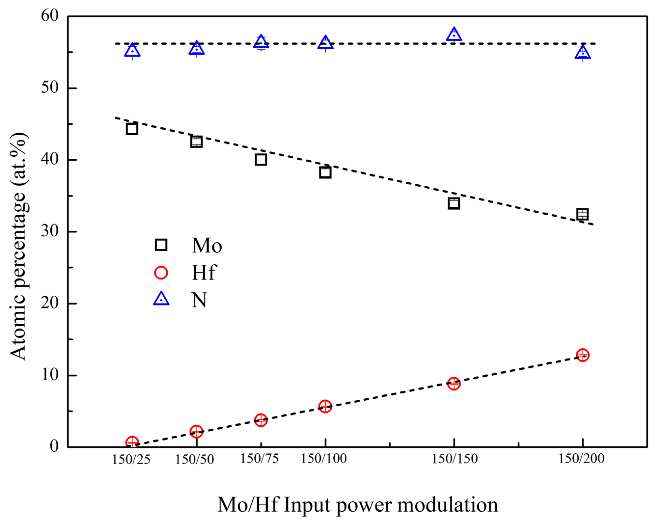
Figure 1 shows the composition of various (Mo, Hf)N coatings with respect to Mo/Hf input power modulation during sputtering, which is also listed in Table 1. The N content of (Mo, Hf)N coatings is steady at a level of 54.8–57.3 at.% without obvious fluctuations. When Hf target input power rises, the content of Hf increases linearly from 0.6 to 12.8 at.%. Meanwhile, Mo contents decrease monotonically from 44.3 to 32.4 at.%. According to these trends, a constant total metallic atom ratio in (Mo, Hf)N coatings is expected.
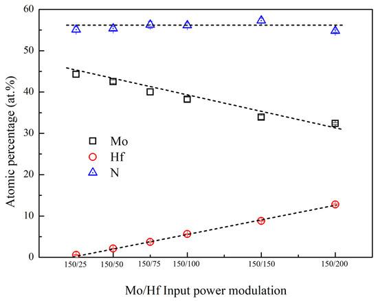
Figure 1.
The composition of various coatings as a function of input power modulation.
Table 1 summarizes the sample designation, power modulation on Mo/Hf, composition, and deposition rate of nitride coatings. For (Mo, Hf)N coatings, as Hf target input power rises, the content of Hf increases, and that of Mo goes down in a linear fashion. The Mo/Hf ratio descends drastically from 73.8 to 2.5 as Hf input power increases, while the deposition rate rises from 6.0 to 9.7 nm/min. In addition, the deposition rates of MoN and HfN are 7.4 and 2.1, respectively. Mo ion is easier to form nitride with N than Hf ion, especially in low Hf input power conditions. The phenomenon is owing to higher sputter yield of Mo and lower plasma energy input for Hf. One can see in Table 1 that the ratios of (Mo + Hf)/N are stable at 0.8, which confirms that in this system, whole samples are steady in nitride formation regardless of input power modulation. For (Mo, Hf)N films, the deposition rates of samples B to G increase with Hf input power. In addition, the ratios can be divided into two groups. For samples B to D, the deposition rates fall between those of samples A and H, implying that the addition of Hf hinders the deposition of nitride coatings. On the contrary, for samples F and G, a simple add-up of deposition rates of samples A and H is found. Sample E shows a deposition rate in the transition region between groups of B–D and F–G.
3.2. Microstructure Analysis
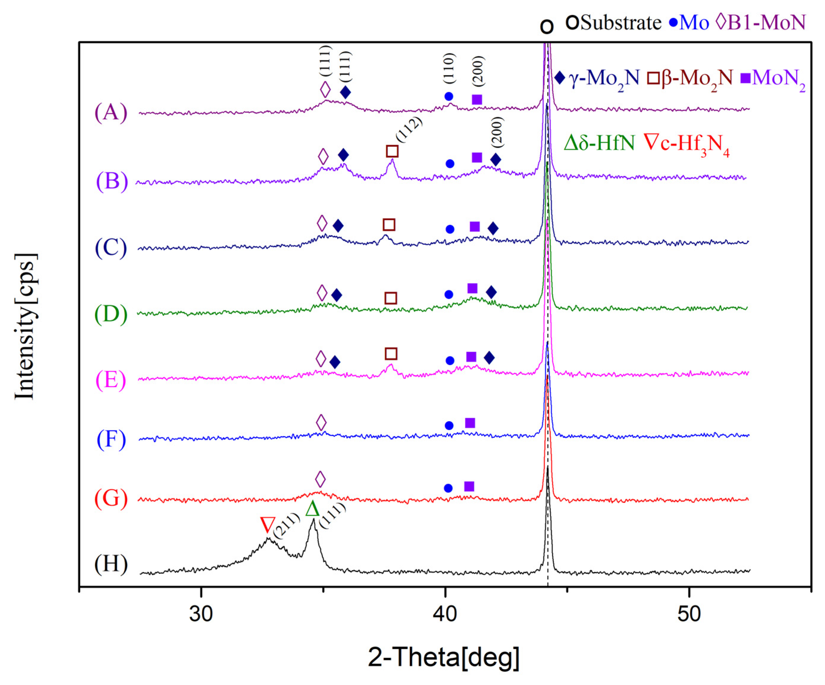
Figure 2 presents the X-ray diffraction patterns of phases for various samples. The diffraction peak of interlayer for Mo(110) shows up in sample A to G. The MoN coating has B1-MoN(111), γ-Mo2N(111), and MoN2(200) phases, while the HfN coating possesses δ-HfN(111) and c-Hf3N4(211) phases. In the literature [14,20,21], MoN coatings with MoN(111) orientations and Mo2N(111), (200) peaks were confirmed in range of 30–45 two theta degrees. The HfN(111) and Hf3N4(211) peaks around two theta of 32–34 degrees are demonstrated for HfN films [8,23]. For the co-sputtering (Mo, Hf)N thin films B to E, multiple polycrystalline phases with various facets, such as B1-MoN(111), β-Mo2N(112), γ-Mo2N(111), (200), and MoN2(200) were discovered as Hf target input power was tuned to between 25 and 100W. As compared to MoN and HfN single element nitride coatings, the co-sputtering (Mo, Hf)N in low Hf input power, i.e., low Hf content incorporation from 0.6 to 5.6 at.%, could lead to MoN, Mo2N, and MoN2 multiple phases feature. The major difference is between MoN and B to E films as the appearance of β and γ-Mo2N phases. On the other hand, coatings F and G, B1-MoN(111), and MoN2(200) phases existed with relatively low intensity, and β and γ-Mo2N peaks diminished. The phase transition of films with input power modulation is evident. For samples B to G, their intensities of peaks gently decreased with broadened widths as Hf content increased. It was noticed that the peaks signal shift slightly toward lower two theta angle with Hf contents for samples B to E, showing a gradual solid-solutioning effect for (Mo, Hf)N films. As a result, solid-solutioning and multiphase phenomenon occur for the (Mo, Hf)N co-sputtering coatings. Yet, the detailed microstructure analysis is required for further clarification of the phase evolution of the (Mo, Hf)N films.

Figure 2.
The X-ray diffraction patterns for phase identification of various nitride coatings.
3.3. Identification of Nanostructure
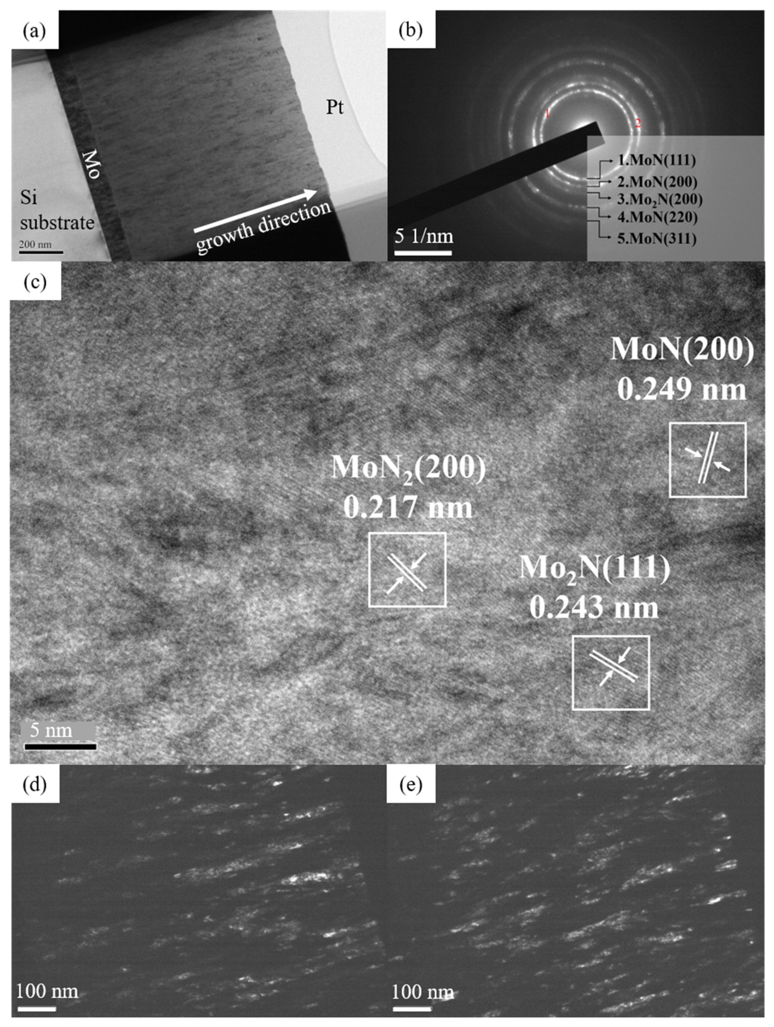
For detail microstructure analysis on MoN, HfN, and (Mo, Hf)N coatings, the transmission electron microscopy (TEM) with cross-sectional and high-resolution imaging, selected area diffraction, and dark field imaging, was employed. Figure 3, Figure 4, Figure 5, Figure 6 and Figure 7 present the microstructure features of samples A, C, E, F and H, respectively. In the coating overviews in Figure 3a, Figure 4a, Figure 5a, Figure 6a and Figure 7a, all the nitride films exhibit columnar crystalline structure along growth direction. The diffraction rings in Figure 3b were recognized as (111), (200), (220), and (311) for MoN and (200) for Mo2N phases. Those phases were frequently found in the MoN coating system [14,33,34,35,36]. In Figure 3c, the interplanar distances d = 0.249 nm for MoN(111), d = 0.243 nm for Mo2N(111), and d = 0.217 nm for MoN2(200) were demonstrated with high-resolution TEM images for MoN coating. For HfN coating, the diffraction rings in Figure 7b belong to the HfN phase with (111), (200), (220) and (311) facets [8,26,37]. The interplanar distances d = 0.267 nm for HfN(111), d = 0.235 nm for HfN(200), and d = 0.278 nm for Hf3N4(211), were confirmed in Figure 7c. For various (Mo, Hf)N films in Figure 4 and Figure 5, diffraction rings were generated from the MoN phase with (111), (200), (220), and (311) facets and Mo2N phase with (200) facets. The coexistence of MoN, and Mo2N phases in the (Mo, Hf)N coatings was evident, implying that the multiple phase feature was formed in low Hf contents ternary refractory nitride system. However, in Figure 6c there is no Mo2N phase found due to the high contents of Hf. In addition, the lattice spacing of MoN(111), Mo2N(111), and (200) for sample C and sample E is shown in Figure 4b and Figure 5c. These spacing distances can also be evaluated as 0.249, 0.244, 0.209, and 0.217 nm for MoN(111), Mo2N(111), Mo2N(200), and MoN2(200), respectively. These phases and related interplanar spacings demonstrated through TEM high-resolution images coincided the results in X-ray phase identification. Consequently, a multiple phase feature was checked again for the (Mo, Hf)N films. As for sample F, the interplanar distances for MoN(200) and MoN2(200) were 0.250 and 0.217 nm as shown in Figure 6b,c. The (Mo, Hf)N coating with 5.6 at.% Hf, sample E, exhibited a polycrystalline and a multiphase feature. From the dark field images in Figure 4, Figure 5, Figure 6 and Figure 7d,e, all the films possessed a columnar structure feature. The grains of sample A, C, and E presented a short and thin fashion. Contrarily, sample F showed long and thick grains along growth direction. Those microstructure evolution were due to the difference in Hf content of the ternary refractory metal nitride films. When (Mo, Hf)N coatings with low Hf content were less than 5.6 at.%, the columnar crystal structure of Mo grew with Hf incorporation to form a solid solution. Moreover, the dash columnar grains observed in Figure 4e and Figure 5e further implied a finer grain feature. On the other hand, as the Hf content was beyond 8.8 at.%, the growth of crystal was prolonged up to 200 to 300 nm, as illustrated in Figure 6d,e. Some of the columnar grains possessed a wide width of approximately 100 nm, as shown with arrows in Figure 6d.

Figure 3.
(a) Cross-sectional TEM image, (b) SAED, (c) HR-TEM image, (d) dark field images of point 1 and (e) point 2 in (b), for sample A.
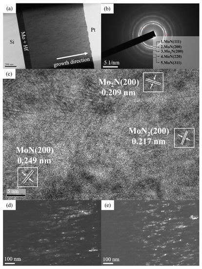
Figure 4.
(a) Cross-sectional TEM image, (b) SAED, (c) HR-TEM image, (d) dark field images of point 1 and (e) point 2 in (b), for sample C.
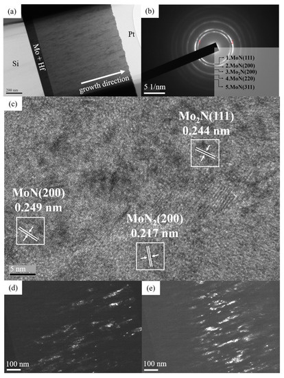
Figure 5.
(a) Cross-sectional TEM image, (b) SAED, (c) HR-TEM image, (d) dark field images of point 1 and (e) point 2 in (b), for sample E.
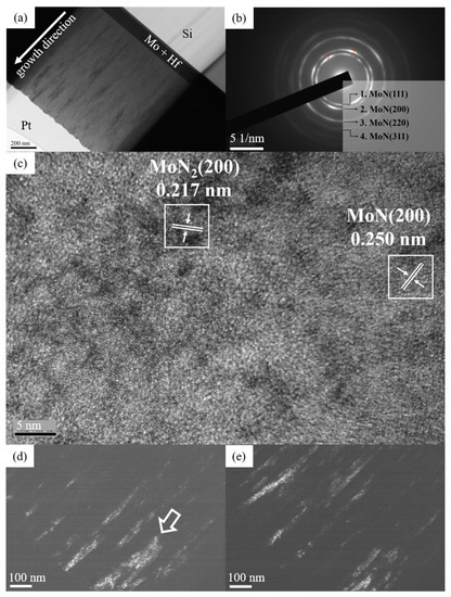
Figure 6.
(a) Cross-sectional TEM image, (b) SAED, (c) HR-TEM image, (d) dark field images of point 1 and (e) point 2 in (b), for sample F.
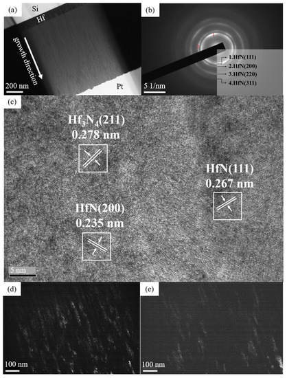
Figure 7.
(a) Cross-sectional TEM image, (b) SAED, (c) HR-TEM image, (d) dark field images of point 1 and (e) point 2 in (b), for sample H.
3.4. Mechanical Behavior
3.4.1. Indentation Hardness and Elastic Modulus
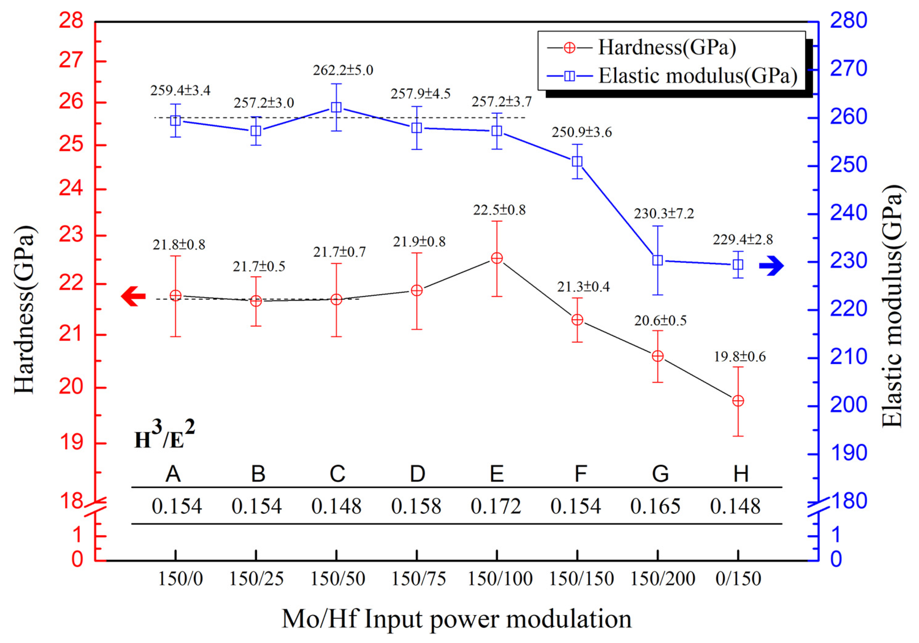
Mechanical characteristics of hardness, elastic modulus, and calculated H3/E2 index of various thin films are shown in Figure 8. The hardness of MoN coating was 21.8 GPa and HfN film had was slightly lower at 19.8 GPa. When Mo/Hf input power modulation changes from 150/25 to 150/100 W/W, the hardness of the coatings increases gradually and slightly from 21.7, 21.7, 21.9 and then reaches a maximum of 22.5 GPa. Then, the (Mo, Hf)N coatings’ hardness decreases as the input power modulation goes from 150/150 to 150/200 W/W. In the literature on ternary nitride films, including TiCrN and HfMoN, a similar trend in hardness could be observed [10,31]. When the addition of elements gradually increased, the hardness value approached a maximum and then went down. For elastic modulus, the values were kept at a level of approximately of 260 GPa for MoN and (Mo, Hf)N films produced with a modulation of 150/25 to 150/100 W/W. There was a drop in modulus from 250.9.

Figure 8.
Indentation Hardness, elastic modulus, and H3/E2 values of various nitride coatings with respect.
To input power modulation to 230.3 GPa was observed as the input power on Hf was further raised. The lowest elastic modulus of 229.5 GPa was found for the HfN film. The H3/E2 of (Mo, Hf)N coatings, as illustrated in the inserted table, also showed a similar trend to hardness and reach to the maximum of 0.172 at modulation of 150/100 W/W. If composition and microstructure were taken into account, when Hf content is in the range of 0.6 to 5.6 at.%, multiple phases and solid solutioning were observed. Additionally, the co-sputtering (Mo, Hf)N coatings could be effectively improved in mechanical properties. Thus, a higher hardness and an elastic modulus are resultant.
3.4.2. Wear Characteristic
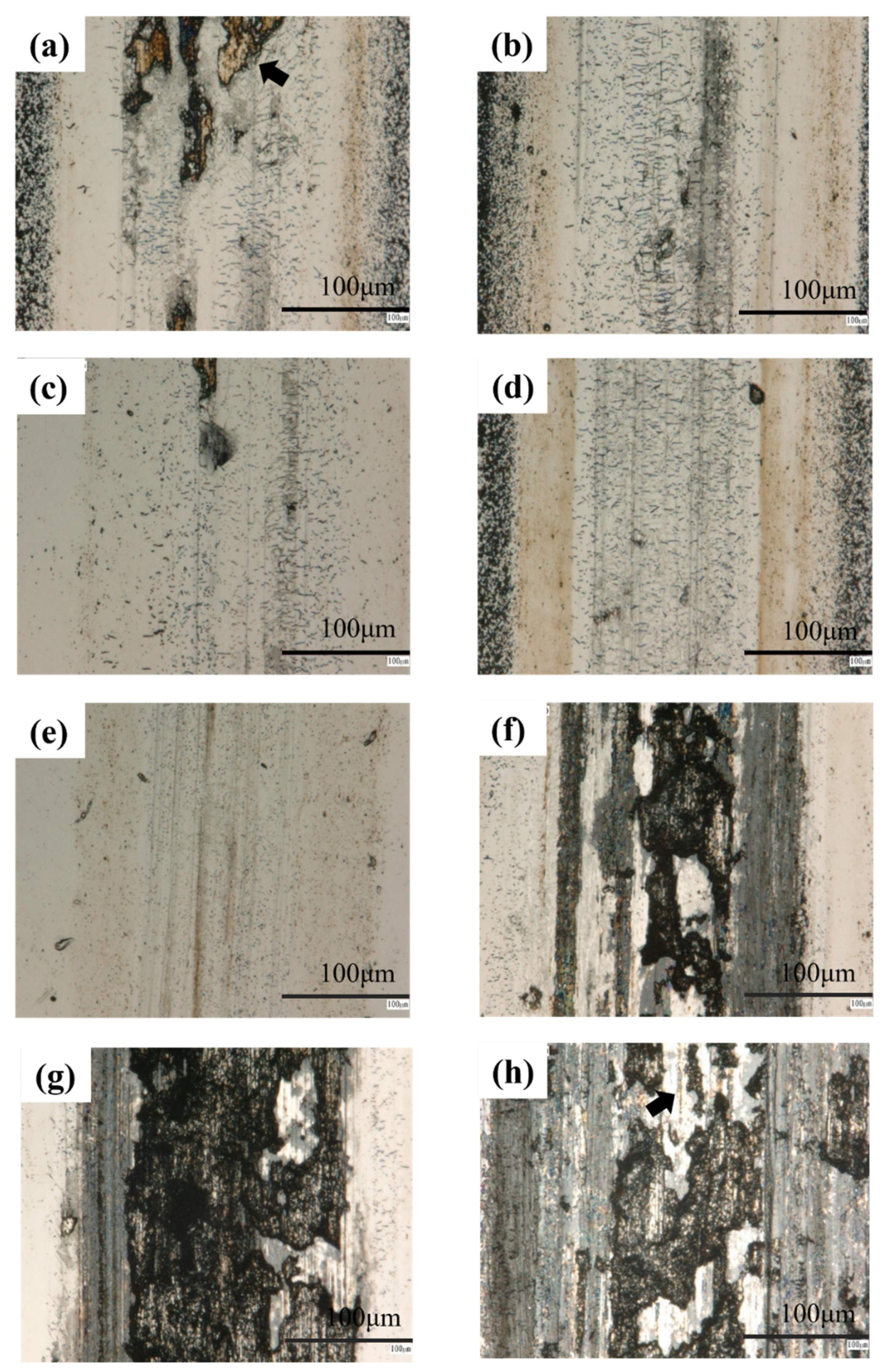
The tribological behavior of various coatings was evaluated by the wear test using Simple Harmonic back-and-forth linear sliding method. The applied normal force, single trip and total wear distance were set as 3.2 N, 10 mm, and 100 m, respectively. Figure 9 shows the wear track morphology of different coatings. For MoN film, the track width was about 300 μm with a partially severer wear area, such as the dark region marked by arrows in Figure 9a. The track damage of the HfN coating was severer than that of MoN coating as shown in Figure 9h. Not only the dark severer wear region, but also adhesive wear shown in the white region in Figure 9h, were observed all through the track. The lower hardness, elastic modulus, and H3/E2 index might be responsible for the poor wear resistance. The (Mo, Hf)N coatings with Hf content lower than 5.6 at.%, i.e., samples B to E, presented smooth surface and shallow wear depth without significant failure. On the contrary, as illustrated in Figure 9f,g, respectively, samples F and G showed dark color and deep wear depth similar to that of the HfN coating. In the above-mentioned microstructure, it was believed that the (Mo, Hf)N coatings with Hf contents below 5.6 at.% exhibited a well tribological property due to multiphases strengthening and a high index H3/E2. The coating with Hf contents over 8.8 at.%, where Mo2N phase disappeared in contrast, had an easier wear-off characteristic. In short, among all of the coatings, sample E that possessed B1-MoN(111), β-Mo2N(112), γ-Mo2N(111), (200), and MoN2(200) multiple phase features and presented a superior mechanical performance. The (Mo, Hf)N RMN coating with enhanced mechanical properties casts a potential application on surface protection. The properly strengthened (Mo, Hf)N films could be beneficial for hardness and wear resistance improvements of working component surfaces.
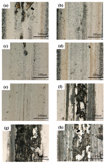
Figure 9.
Wear scar images of (a) MoN, (b–g) various (Mo, Hf)N, and (h) HfN coatings.
4. Conclusions
The MoN, (Mo, Hf)N, HfN coatings were fabricated, and their composition, microstructure, and mechanical characteristic were discussed and compared. With an input power modulation of Mo and Hf targets, the MoN, HfN, and (Mo, Hf)N coatings with 0.6 to 12.8 at.% Hf were produced with various microstructure features. In X-ray diffraction patterns, MoN, Mo2N, and MoN2 phases were found for the MoN coating, while the HfN and Hf3N4 phases were observed for the HfN coating. For (Mo, Hf)N coatings, a multiple-phase feature containing B1-MoN, β-Mo2N, γ-Mo2N, and MoN2 phases were realized. Declined intensity and a slight shift in two theta angles for MoN and MoN2 peaks with increased Hf content were seen owing to the solid-solution effect. As compared to MoN and HfN coatings, the co-sputtering (Mo, Hf)N films’ mechanical properties were weakened in high Hf contents ≥ 8.8 at.%. In contrast, when input power was 150/100 W/W and the resultant Hf content was 5.6 at.%, the (Mo, Hf)N coating presented a superior mechanical performance, such as a maximum hardness of 22.5 GPa and a high-value H3/E2 of 0.172. The wear test showed that the coating’s resistance to chipping failure could successfully be improved in (Mo, Hf)N films with Hf in range of 0.6 to 5.6 at.%. Those tribological properties were due to B1-MoN, β-Mo2N, γ-Mo2N, and MoN2 multiphase strengthening and solid-solution feature.
Author Contributions
Conceptualization, F.-B.W.; Data curation, S.-Y.H.; Formal analysis, S.-Y.H.; Funding acquisition, F.-B.W.; Methodology, S.-Y.H. and F.-B.W.; Resources, F.-B.W.; Writing – original draft, S.-Y.H.; Writing – review & editing, F.-B.W. All authors have read and agreed to the published version of the manuscript.
Funding
The financial supports from Ministry of Science and Technology, Taiwan, under contracts Nos. MOST-107-2221-E-239-004-MY3 and MOST-110-2221-E-239-006- are highly appreciated. Technical support from FE-EPMA Lab in National Tsing Hua University is also acknowledged.
Institutional Review Board Statement
Not applicable.
Informed Consent Statement
Not applicable.
Data Availability Statement
Not applicable.
Conflicts of Interest
The authors declare no conflict of interest.
References
- Lévy, F.; Hones, P.; Schmid, P.E.; Sanjinés, R.; Diserens, M.; Wiemer, C. Electronic states and mechanical properties in transition metal nitrides. Surf. Coat. Technol. 1999, 120–121, 284–290. [Google Scholar] [CrossRef]
- Mei, Z.G.; Bhattacharya, S.; Yacout, A.M. First-principles study of fracture toughness enhancement in transition metal nitrides. Surf. Coat. Technol. 2019, 357, 903–909. [Google Scholar] [CrossRef]
- He, C.; Zhang, J.; Wang, J.; Ma, G.; Zhao, D.; Cai, Q. Effect of structural defects on corrosion initiation of TiN nanocrystalline films. Appl. Surf. Sci. 2013, 276, 667–671. [Google Scholar] [CrossRef]
- Lin, J.; Sproul, W.D.; Moore, J.J. Tribological behavior of thick CrN coatings deposited by modulated pulsed power magnetron sputtering. Surf. Coat. Technol. 2012, 206, 2474–2483. [Google Scholar] [CrossRef]
- Zhu, F.; Zhu, K.; Hu, Y.; Ling, Y.; Wang, D.; Peng, H.; Xie, Z.; Yang, R.; Zhang, Z. Microstructure and Young’s modulus of ZrN thin film prepared by dual ion beam sputtering deposition. Surf. Coat. Technol. 2019, 374, 997–1005. [Google Scholar] [CrossRef]
- Fenker, M.; Balzer, M.; Büchi, R.V.; Jehn, H.A.; Kappl, H.; Lee, J.J. Deposition of NbN thin films onto high-speed steel using reactive magnetron sputtering for corrosion protective applications. Surf. Coat. Technol. 2003, 163–164, 169–175. [Google Scholar] [CrossRef]
- Xiang, J.Y.; Wu, F.B. Gas inlet and input power modulated sputtering molybdenum nitride thin films. Surf. Coat. Technol. 2017, 332, 161–167. [Google Scholar] [CrossRef]
- Ke, Y.E.; Chen, Y.I. Mechanical properties, bonding characteristics, and thermal stability of magnetron-sputtered HfNx films. Surf. Coat. Technol. 2020, 388, 125575. [Google Scholar] [CrossRef]
- Riekkinen, T.; Molarius, J.; Laurila, T.; Nurmela, A.; Suni, I.; Kivilahti, J.K. Reactive sputter deposition and properties of TaxN thin films. Microelectron. Eng. 2002, 64, 289–297. [Google Scholar] [CrossRef]
- Li, H.; Li, J.; Liu, Z.; Huang, J.; Kong, J.; Xiong, D. Mechanical and tribological properties of Hf1−xMoxNy thin films as a function of Mo contents. Surf. Coat. Technol. 2019, 375, 589–599. [Google Scholar] [CrossRef]
- Yao, S.H.; Su, Y.L.; Kao, W.H.; Cheng, K.W. Evaluation on wear behavior of Cr–Ag–N and Cr–W–N PVD nanocomposite coatings using two different types of tribometer. Surf. Coat. Technol. 2006, 201, 2520–2526. [Google Scholar] [CrossRef]
- Zeman, P.; Čerstvý, R.; Mayrhofer, P.H.; Mitterer, C.; Musil, J. Structure and properties of hard and superhard Zr–Cu–N nanocomposite coatings. Mater. Sci. Eng. A 2000, 289, 189–197. [Google Scholar] [CrossRef]
- Ezirmik, K.V.; Rouhi, S. Influence of Cu additions on the mechanical and wear properties of NbN coatings. Surf. Coat. Technol. 2014, 260, 179–185. [Google Scholar] [CrossRef]
- Kim, S.; Yoon, H.W.; Moon, K.I.; Lee, C.S. Mechanical and friction behavior of sputtered Mo–Cu–(N) coatings under various N2 gas flow using a multicomponent single alloy target. Surf. Coat. Technol. 2021, 412, 127060. [Google Scholar] [CrossRef]
- Hahn, R.; Tymoszuk, A.; Wojcik, T.; Kirnbauer, A.; Kozák, T.; Čapek, J.; Sauer, M.; Foelske, A.; Hunold, O.; Polcik, P.; et al. Phase formation and mechanical properties of reactively and non-reactively sputtered Ti-B-N hard coatings. Surf. Coat. Technol. 2021, 420, 127327. [Google Scholar] [CrossRef]
- Wo, P.C.; Munroe, P.R.; Li, Z.; Jiang, Z.T.; Xie, Z.H.; Zhou, Z.F.; Li, K.Y. Factors governing the mechanical behaviour of CrSiN coatings: Combined nanoindentation testing and transmission electron microscopy. Mater. Sci. Eng. A 2012, 534, 297–308. [Google Scholar] [CrossRef] [Green Version]
- Diyatmika, W.; Cheng, C.Y.; Lee, J.W. Fabrication of Cr-Si-N coatings using a hybrid high-power impulse and radio-frequency magnetron co-sputtering: The role of Si incorporation and duty cycle. Surf. Coat. Technol. 2020, 403, 126378. [Google Scholar] [CrossRef]
- Mae, T.; Nose, M.; Zhou, M.; Nagae, T.; Shimamura, K. The effects of Si addition on the structure and mechanical properties of ZrN thin films deposited by an r.f. reactive sputtering method. Surf. Coat. Technol. 2001, 142–144, 954–958. [Google Scholar] [CrossRef]
- Oliveira, J.C.; Manaia, A.; Cavaleiro, A.; Vieira, M.T. Structure, hardness and thermal stability of Ti(Al,N) coatings. Surf. Coat. Technol. 2006, 201, 4073–4077. [Google Scholar] [CrossRef] [Green Version]
- Wang, T.; Zhang, G.; Liu, Z.; Jiang, B. Oxidation behavior of magnetron sputtered Mo2N/AlN multilayer coatings during heat treatment. Ceram. Int. 2015, 41, 7028–7035. [Google Scholar] [CrossRef]
- Tillmann, W.; Kokalj, D.; Stangier, D. Influence of the deposition parameters on the texture and mechanical properties of magnetron sputtered cubic MoNx thin films. Materialia 2019, 5, 100186. [Google Scholar] [CrossRef]
- Li, H.; Liu, Z.; Li, J.; Huang, J.; Kong, J.; Wu, Q.; Xiong, D. Effects of Hf addition on the structure, mechanical and tribological properties of CrN film. Surf. Coat. Technol. 2020, 397, 126067. [Google Scholar] [CrossRef]
- Zhang, D.; Qi, Z.; Wei, B.; Shen, H.; Wang, Z. Microstructure and corrosion behaviors of conductive Hf/HfN multilayer coatings on magnesium alloys. Ceram. Int. 2018, 44, 9958–9966. [Google Scholar] [CrossRef]
- Hart, G.; Klein, B.M. Phonon and elastic instabilities in MoC and MoN. Phys. Rev. B 2000, 61, 3151–3154. [Google Scholar] [CrossRef] [Green Version]
- Koutná, N.; Holec, D.; Friák, M.; Mayrhofer, P.H.; Šob, M. Stability and elasticity of metastable solid solutions and superlattices in the MoN–TaN system: First-principles calculations. Mater. Des. 2018, 144, 310–322. [Google Scholar] [CrossRef]
- Gu, Z.; Hu, C.; Huang, H.; Zhang, S.; Fan, X.; Wang, X.; Zheng, W. Identification and thermodynamic mechanism of the phase transition in hafnium nitride films. Acta Mater. 2015, 90, 59–68. [Google Scholar] [CrossRef]
- Mayrhofer, P.H.; Rachbauer, R.; Holec, D.; Rovere, F.; Schneider, J.M. Protective Transition Metal Nitride Coatings. In Comprehensive Materials Processing; Hashmi, S., Batalha, G.F., Tyne, C.V., Yilbas, B., Eds.; Elsevier: Amsterdam, The Netherlands, 2014; Chapter 4.14; pp. 355–388. [Google Scholar]
- Wu, F.B.; Chen, Y.I.; Lee, J.W.; Duh, J.G. Multilayer Transition Metal Nitride Protective Coatings. In Protective Thin Coatings Technology; Zhang, S., Ting, J.M., Wu, W.Y., Eds.; CRC Press: Boca Raton, FL, USA, 2022; Chapter 3; pp. 95–139. [Google Scholar]
- Kimura, A.; Hasegawa, H.; Yamada, K.; Suzuki, T. Effects of Al content on hardness, lattice parameter and microstructure of Ti1−xAlxN films. Surf. Coat. Technol. 1999, 120–121, 438–441. [Google Scholar] [CrossRef]
- Pacher, F.; Mayrhofer, P.H.; Holec, D. Vacancy-driven extended stability of cubic metastable Ta-Al-N and Nb-Al-N phases. Surf. Coat. Technol. A 2017, 326, 37–44. [Google Scholar] [CrossRef] [Green Version]
- Han, J.G.; Myung, H.S.; Lee, H.M.; Shaginyan, L.R. Microstructure and mechanical properties of Ti–Ag–N and Ti–Cr–N superhard nanostructured coatings. Surf. Coat. Technol. 2003, 174–175, 738–743. [Google Scholar] [CrossRef]
- Tsai, D.C.; Chang, Z.C.; Kuo, L.Y.; Lin, T.J.; Lin, T.N.; Shieu, F.S. Solid solution coating of (TiVCrZrHf)N with unusual structural evolution. Surf. Coat. Technol. 2013, 217, 84–87. [Google Scholar] [CrossRef]
- Roberson, S.L.; Finello, D.; Davis, R.F. Growth of MoxN films via chemical vapor deposition of MoCl5 and NH3. Surf. Coat. Technol. 1998, 102, 256–259. [Google Scholar] [CrossRef]
- Qian, J.; Li, S.; Pu, J.; Cai, Z.; Wang, H.; Cai, Q.; Ju, P. Effect of heat treatment on structure and properties of molybdenum nitride and molybdenum carbonitride films prepared by magnetron sputtering. Surf. Coat. Technol. 2019, 374, 725–735. [Google Scholar] [CrossRef]
- Krysina, O.V.; Ivanov, Y.F.; Koval, N.N.; Prokopenko, N.A.; Shugurov, V.V.; Petrikova, E.A.; Tolkachev, O.S. Composition, structure and properties of Mo-N coatings formed by the method of vacuum-arc plasma-assisted deposition. Surf. Coat. Technol. 2021, 416, 127153. [Google Scholar] [CrossRef]
- Mikula, M.; Uzon, S.; Hudec, T.; Grančič, B.; Truchlý, M.; Roch, T.; Švec, P.; Satrapinskyy, L.; Čaplovičová, M.; Greczynski, G.; et al. Thermally induced structural evolution and age-hardening of polycrystalline V1−xMoxN (x ≈ 0.4) thin films. Surf. Coat. Technol. 2021, 405, 126723. [Google Scholar] [CrossRef]
- Zhao, X.; Li, H.; Li, J.; Hu, J.; Huang, J.; Kong, J.; Wu, Q.; Shi, Y.; Xiong, D. Mechanical and tribological behaviors of hard and tough TaxHf1−xN films with various Ta contents. Surf. Coat. Technol. 2020, 403, 126412. [Google Scholar] [CrossRef]


Publisher’s Note: MDPI stays neutral with regard to jurisdictional claims in published maps and institutional affiliations. |
© 2022 by the authors. Licensee MDPI, Basel, Switzerland. This article is an open access article distributed under the terms and conditions of the Creative Commons Attribution (CC BY) license (https://creativecommons.org/licenses/by/4.0/).