1. Introduction
Bucket foundations are a new form of suction foundation for offshore wind power engineering. With the extension of offshore wind power into deep water, the advantages of bucket foundations over traditional gravity and pile foundations are becoming more apparent. These advantages include convenience of installation and transportation, high anti-overturning capacity, small steel consumption, and capability for recycling and reuse [
1]. For small structures with small loads and burial depths, a single bucket is sufficient, whereas large structures with a large load and large burial depth require grouped buckets. The bearing capacity and stability of a bucket foundation are closely related to the effect of penetration installation, and successful placement of the bucket foundation is essential for normal use [
2,
3,
4,
5].
Suction penetration of single-bucket foundations has been extensively studied by scale model tests [
6,
7], numerical simulations [
8,
9], and theoretical research [
10,
11]. Jacked penetration of bucket foundations has also been studied. Different research methods have been used to assess the penetration resistance of bucket foundations during jacked penetration and changes in the earth pressure inside the bucket, including scale model tests [
12,
13,
14], numerical modeling [
15], and theoretical studies [
16,
17,
18]. Because of the limitations of testing methods and testing techniques, there has been limited research on jacked penetration of grouped buckets.
In this study, non-contact digital image correlation was applied to carry out model testing of a group of two buckets during jacked penetration in sand. The superposition effect of grouped buckets and the formation mechanism of soil plugs within the buckets were assessed. Studying the deformation field allowed clarification of the deformation pattern of the soil surrounding and within the buckets. The results of this study will be useful for developing predictive models for grouped-bucket foundation penetration and design.
2. Materials and Methods
2.1. Experimental Setup
The experimental setup consisted of a universal testing machine and an image acquisition system (
Figure 1). The universal testing machine was an MTS CMT4304 (MTS, Shenzhen, China), the load sensor maximum measured load was 30 kN, and the maximum measured displacement range was 50 mm for the displacement sensor (LVDT), which can be used to visualize force and displacement during jacked penetration of a bucket foundation; they all had a relative error of ±0.5%. The image acquisition system was composed of a charge coupled device (CCD) high-speed camera and a Strainmaster-Davis 8.0 image analysis system (LaVision, Bielefeld, Germany). The camera contained a SONY scientific research chip with a resolution of 2460 pixels × 2060 pixels, a pixel size of 3.45 μm × 3.45 μm, and an exposure time of 100 μs × 80 ms. The maximum acquisition rate was 200 fps when using the Camlink special interface, which met the requirements of measurement accuracy and provided hardware support for the successful completion of the test. The Strainmaster-Davis 8.0 image analysis system is based on digital image correlation and an optical grayscale color standard, based on high-quality imaging technology and a brightness color standard. Through the association of two frames of images in the area to be measured, the 2D or 3D deformation field can be analyzed and visualized in real time.
2.2. Starting Material
Standard sand was selected for the test. In order to study the influence of soil density, three density conditions were tested: loose (average dry density,
ρd = 1.48 g/cm
3; corresponding relative density, Dr = 25%), medium (
ρd = 1.55 g/cm
3, Dr = 55%), and dense (
ρd = 1.63 g/cm
3, Dr = 75%). The angles of friction corresponding to the three density conditions were 31°, 35°, and 38°, respectively. The particle-size distribution of the sand is shown in
Figure 2. The soil properties play an important role in the design of the foundation and the method used to prepare soil samples has an important influence on the remolding sand density [
19]. To obtain better compaction, the soil samples were prepared following the method used by Vanitha [
20]. In cohesive soil with a fully saturated condition or partially saturated condition, water content has an important effect on the bearing capacity of the bucket foundation, which is our subsequent research [
21].
2.3. Test Model
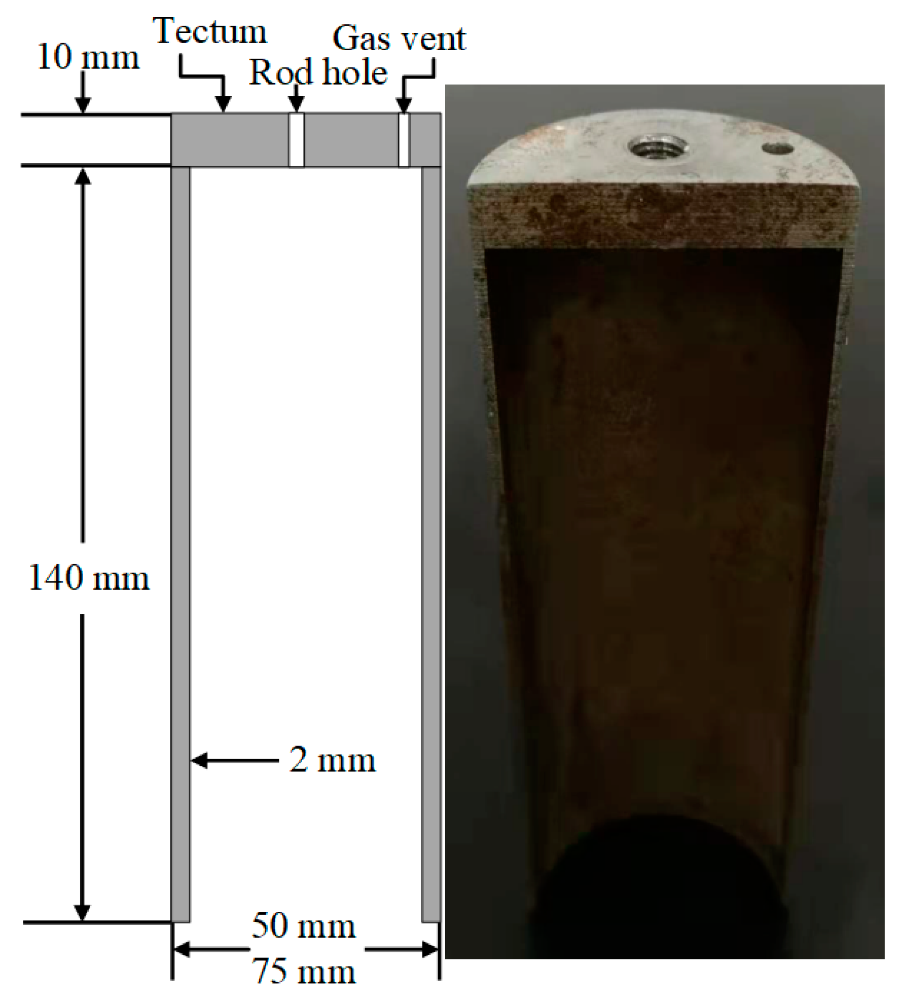
The model box was made of organic transparent glass with dimensions of 80 cm × 70 cm × 70 cm (length × width × height). All model buckets were semi-cylindrical, with dimensions of 15 cm height, 14 cm inner net height, 5 cm diameter, and 0.2 cm thickness (
Figure 3). The bucket foundation was connected to the loading beam of the universal testing machine by a solid aluminum alloy rod. As the loading beam of the universal testing machine moved down, a bucket foundation or a group of two buckets jacked at the same time under static pressure. In the jacked penetration test, the universal testing machine was used to control the force and displacement of the grouped buckets. To allow changes in the spacing of the grouped buckets, the universal testing machine fixture was optimized, and a steel beam was included to adjust the bucket spacing (
Figure 1).
2.4. Test Program
To study the deformation characteristics of sandy soil around grouped buckets during jacked penetration, a series of physical model tests were conducted under different conditions, including different sand densities, bucket diameters, and bucket spacings. Details of the test program are provided in
Table 1. The code used for test numbering incorporates the number of buckets, sand density, bucket diameter, and bucket spacing. In the test numbers, the prefix G indicates grouped buckets; S denotes a single bucket; 27, 55, and 75 indicate the percentage sand density of Dr; L is the bucket spacing; and D is the bucket diameter, where the dimensions of 5 and 7.5 cm were used. H/D is the ratio of the bucket height to the bucket diameter. L/D is the ratio of the bucket spacing to the bucket diameter.
Jacked penetration of a group of buckets is more difficult to test than that of a single bucket foundation. During the entire test process, the soil density around the buckets should be controlled and the buckets should be kept in the same plane to ensure accurate image acquisition. Moreover, to ensure the accuracy and reliability of the results, synchronization of the force, displacement, and image should be controlled during jacked penetration.
3. Test Results and Analysis
3.1. Penetration Resistance versus Depth Response
Typical penetration resistance versus depth curves for the cases of a single bucket and a two-bucket group with different parameters is illustrated in
Figure 4. The penetration resistance versus depth curve for a two-bucket group is similar to that of the single-bucket case, in that penetration resistance increases linearly at first and then exponentially (
Figure 4). To facilitate the comparative analysis of different configurations, a maximum penetration depth of 140 mm was selected. From the curves, the penetration resistance of a bucket group is not the sum of two independent single buckets; instead, there is an obvious group effect. The interaction between buckets causes the soil between the buckets to become squeezed, and stress overlap occurs. At this stage, the range of soil between buckets from an elasticity to a plastic state becomes larger and larger, which affects the penetration resistance of the bucket group.
To study the influence of different configurations of parameters on the bucket-group effect, we used the effect efficiency (η), which is defined as the ratio of the penetration resistance of a two-bucket group
(PG) to that of a single bucket (
PS) and bucket number (
N) [
22].
The effect efficiencies of a single bucket and a two-bucket group for different values of sand density and bucket diameter are provided in
Table 2. The penetration resistance of a bucket foundation is positively correlated with both sand density and bucket diameter. For a given bucket spacing, the penetration resistance of a bucket group is affected by the group effect, and is not the sum of two independent buckets. As the bucket spacing increases, the group efficiency becomes larger and the penetration resistance of the bucket group approaches the sum of two individual buckets. For 4 D spacing, the group efficiency is negatively correlated with sand density and bucket diameter, but positively correlated with bucket spacing.
3.2. Soil Plug Analysis
During jacked penetration of a bucket foundation, part of the soil is pushed into the bucket and forms a soil column called a soil plug. Under the action of a load, the soil plug will move into the bucket or form a soil arch near the bucket edge, blocking the soil and partially or completely preventing external soil from entering the bucket: this is called the plugging effect [
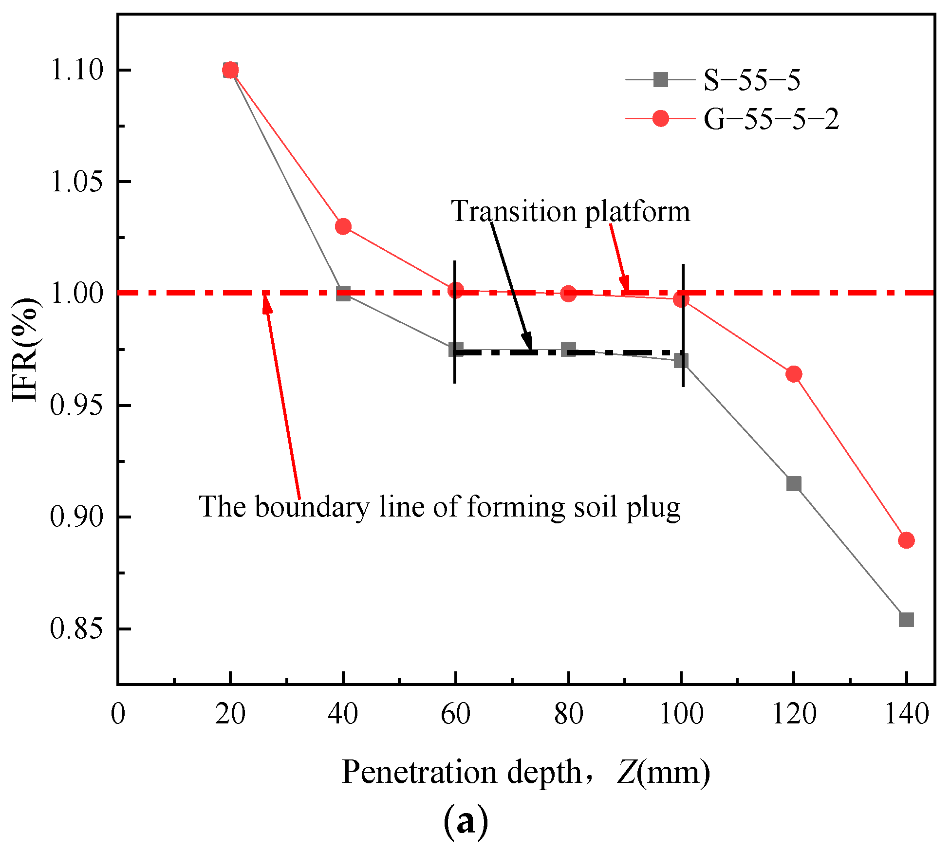
23]. The characteristics of the plugging effect are directly related to the bearing capacity and penetration resistance of the bucket edge. The incremental filling ratio (IFR) is recognized as the most effective parameter to describe the height variation of the soil plug [
24]. The IFR is defined as the ratio of the soil plug length increment (
dL) to the penetration depth increment (
dD), and can be written as
3.2.1. Analysis of Incremental Filling Ratio
Curves of IFR versus penetration depth for a single bucket and a group of two buckets exhibit S-shaped broken lines (
Figure 5a). There is a transition between the 60 and 80 mm penetration depth, corresponding to IFR values of 0.97 for a single bucket and 1 for a group of buckets. For the same penetration depth, the IFR of a single bucket is smaller than that of a bucket group, demonstrating that interactions between buckets weaken the plugging effect.
The relationship between IFR and penetration depth for grouped buckets is plotted for different sand densities (
Figure 5b) and bucket diameters (
Figure 5c). As the sand density increases, the penetration depth of the transition platform decreases and the corresponding IFR decreases (
Figure 5b), indicating that the increased sand density enhances the formation of a soil plug in the bucket. The transition platform disappears as the bucket diameter increases, and the curve approximately forms a hyperbola (
Figure 5c). With increasing bucket diameter, the IFR for the same penetration depth also increases, which implies that a larger bucket diameter retards the formation of a soil plug.
3.2.2. Displacement Field of the Soil Plug
A comparative analysis was performed by comparing pictures recorded at the beginning and different penetration depths during jacket penetration. Strainmaster-Davis 8.0 and Tecplot 10 software were then used to generate a cloud map and contour map, which are shown in
Figure 6, respectively. The arrow in the upper left corner of the figure is the displacement reference value, and the arrow represents the displacement magnitude and direction. The value in the contour map represents the displacement magnitude.
To elucidate the process of soil plug formation, we studied the soil displacement field during jacked penetration for the example of a single bucket of D = 5 cm. Initially (
Figure 6a), the sand exhibits shear sliding when the bucket body penetrates, which is visible as penetration of the edge of the bucket wall into the soil, shear damage to the soil close to the bucket wall, and upward movement of the soil inside the bucket. The range of influence of the bucket is relatively small.
As the penetration depth increases, the soil displacement on both sides of the bucket wall increases markedly compared to that in the previous stage (
Figure 6b). The displacement and range of upward movement of soil in the bucket both decrease. The whole displacement of the soil plug is similar 0.4 D above the bucket edge. This part of the soil can be regarded as the plug core, which has been called the “effective height of the soil plug” in some previous studies [
25]. The displacement of soil outside the bucket wall is much larger than that inside.
When the penetration depth reaches 100 mm (
Figure 6c), three zones of soil displacement in the bucket can be distinguished. The equivalent displacement area within the depth range −40 to −80 mm is a convex arch, indicating that the soil displacement in the center of the bucket is small, whereas the soil displacement at the bucket wall is larger. In the depth range of −80 to −140 mm, a V-shaped plug core region is formed. The soil mass below the bucket edge is compressed and moves downward, forming a lower convex arch.
When the penetration depth reaches −140 mm (
Figure 6d), the soil displacement from the ground to the base of the bucket is the same as in the previous phase, but the proportion occupied by the plug core increases, consistent with the IFR curve. When the bucket end reaches a depth of ca. −200 mm, the equivalent displacement area forms an epirelief arch. Soil displacement is large in the middle of this region, but small on both sides.
3.3. Deformation Field around the Bucket Foundation
Traditional model testing mainly analyzes the mechanical behavior of a bucket foundation during jacked penetration based on the relationship between penetration resistance and depth. This type of analysis can only obtain the external performance of the system, and cannot be used to assess the internal mechanism. The limitations of the traditional test method can be overcome by applying the force−displacement relationship to analyze bucket−soil interactions within the bucket. By combining the traditional test method with digital image correlation, the displacement field during the process of jacked penetration can be visualized, and the mechanism of soil interaction around and inside the bucket can be preliminarily revealed.
3.3.1. Bucket-Group Effect
To study the internal mechanism of the bucket-group effect and the plugging effect during jacked penetration of a bucket foundation with different controlling factors, we analyzed the deformation field at extreme penetration resistance.
We assessed the deformation field for a single bucket with Dr = 55% and D = 5 cm (test number S-55-5). The soil in the bucket can be divided into three parts on the basis of the displacement field (
Figure 7a). The soil from the ground surface to −130 mm moves downward under the action of gravity and friction of the bucket wall, forming a passive arch. From −130 to −190 mm, the plug core bears the main part of the carrying capacity. The passive arch forms a small depth range from −190 mm to the bucket end, with small soil displacement in the middle and large displacement on both sides. The soil below the bucket end is compressed and moves downward, and the initiative arch forms, indicating that the gravity of the soil plug in the bucket and the friction force of the bucket wall are lower than the bearing capacity of the bucket end. A stress core is formed at 0.3 D below the bucket end. In the shear strain field (
Figure 7b), the symmetric shear band runs tangentially to the side of the bucket and extends downward during jacked penetration. The angle between the outward shear band at the bucket edge and the vertical direction is 29°; however, it should be noted that the shear band does not extend downward at a fixed inclination, because there is an inflection point at 1.0 D under the bucket edge. As a result, the soil displacement from the bucket edge to the inflection point is large on both sides and small in the middle, forming an upward initiative arch. The superposition of shear action below the inflection point increases the soil displacement in the middle, resulting in large displacement in the middle and less displacement on both sides, forming a passive arch.
The deformation field for a two-bucket group with Dr = 55%, D = 5 cm, and L/D = 2 is illustrated in
Figure 8 (test number G-55-5-2). There is an obvious overlap in displacement in the area between the two buckets, i.e., there is a group effect (
Figure 8a). The soil mass in the bucket group is obviously different from that in a single bucket (
Figure 7a). No obvious plug core is formed in the bucket. The soil in the bucket and below the bucket edge moves downward. The soil displacement is large in the middle and small on both sides. The contour lines of the displacement field inside and outside the bucket form a convex arch, indicating that the sum of the soil plug gravity in the bucket and the friction force of the bucket wall is greater than the bearing capacity of the foundation at the bucket edge, and the plugging effect of squeezing at the outer bucket end is enhanced. The shear strain field of the bucket group (
Figure 8b shows an angle between the outward shear band and the vertical direction of approximately 32°) and the shear band is directed further outward relative to that of a single bucket. In the area where the inner shear bands are superimposed, the width and range of the shear band shrink, and the height of the shear loss is approximately 0.8 D. There is an obvious group effect between buckets under certain experimental conditions; this effect weakens the formation of the soil plug inside the bucket and strengthens the soil squeezing at the outer edge of the bucket.
3.3.2. Bucket-Group Effect with Different Sand Densities
The displacement field and shear strain field for loose sand (Dr = 27%), D = 5 cm, and a bucket spacing of 2 D is illustrated in
Figure 9. In contrast to the results for medium sand, the area of overlap between the two buckets is not obvious, and the soil displacement inside and outside the buckets is markedly larger than that in the medium sand. No plug core is formed in the bucket, and the range of the displacement fields at the bucket edge is larger than that in the medium sand. The shape of the shear strain field in loose sand is similar to that in medium sand, but the shear loss decreases to 0.6 D and the shear band is inclined at 24° to the vertical.
The displacement and shear strain fields for dense sand are illustrated in
Figure 10. The displacement field between the two buckets is more obvious than for the medium sand in
Figure 8. The range of influence extends 2 D above the bucket edge, and the field is similar in shape to a walnut (
Figure 10a). Compared to the displacement field for medium sand in
Figure 8a, the range of influence of the plug core is greater and the lower passive arch near the bucket edge has disappeared. The shear band at the outer bucket edge is inclined outward at an angle of approximately 40° to the vertical (
Figure 10b). The superposition effect of the shear band at the inner end of the bucket is further enhanced and the shrinkage of the shear band increases.
The bucket group with a spacing of 2 D exhibits a certain group effect, which slows down the formation of soil plugs inside the buckets and enhances the effect of soil squeezing outside the buckets. With greater sand density, the superposition of the displacement field between the buckets and the soil plug inside the bucket are more apparent, the superposition of the shear band at the inner bucket edge is more apparent, and the shear loss increases, indicating that group efficiency and sand density both have a notable impact on the plugging effect inside the bucket.
3.3.3. Bucket-Group Effect for Different Bucket Diameters
The deformation field for a single-bucket foundation with Dr = 55% and D = 7.5 cm (test number S-55-7.5) is plotted in
Figure 11. The shape of the displacement field is similar to that for a bucket diameter of 5 cm (
Figure 7a); however, the plug core area is smaller for a larger bucket diameter, indicating a reduction in the plugging effect. No obvious shear band is present around the bucket wall (compare
Figure 7b and
Figure 11b). There is no inflection point and the angle between the shear band at the bucket edge and the vertical direction is higher.
The displacement field and shear strain field case with Dr = 55%, D = 7.5 cm, and bucket spacing = 2 D are plotted in
Figure 12. Compared to the D = 5 cm group buckets (
Figure 8), the superposition effect of the soil displacement fields between the two buckets is more apparent, consistent with the results in
Table 2. The influence height of the displacement field superposition is approximately 1.4 D. A clear plug core is present in the bucket. The shear loss at the bucket edge is approximately 1.0 D. Thus, a smaller height to diameter ratio (increased bucket diameter) enhances the bucket-group and plugging effects, and decreases the shear action of the bucket wall and the bucket edge.
3.3.4. Bucket-Group Effect with Different Bucket Spacings
Analysis of the deformation field suggests that the penetration resistance arises from two effects: one is the shear stress caused by the friction of the bucket wall and the other is the shear stress caused by the soil shear of the bucket end. The bucket-group effect is mainly caused by relatively close bucket spacing; close spacing allows the buckets to interact with each other, forming the displacement overlap area. In addition, the arch effect caused by the superimposition of the shear stress on the inner wall and that on the bucket end causes the soil in the overlying area to move as a whole. The inner shear band extends less widely than the outer shear zone, resulting in some loss of shear strength. If the base displacement field and shear strain field of the two buckets do not overlap, then each bucket acts individually.
The deformation field for Dr = 55%, D = 5 cm, and L/D = 4 (test number G-55-5-4) is shown in
Figure 13. In this test, the displacement field and shear strain field of the two inner buckets were not superimposed; thus, the displacement field and shear strain field are approximately those of two independent buckets. Deformation fields for other height to diameter ratios and sand densities within 4 D spacing also exhibit a similar pattern, i.e., with increased bucket spacing the group effect gradually decreases, and the deformation field tends to become that of the independent actions of two single buckets.
4. Conclusions
In this study, we combined analyses of force, displacement, and images to systematically study the influences of sand density, diameter, and spacing on the bucket-group effect and the influence of bucket grouping on soil plug formation during jacked penetration for bucket foundations. We also considered the formation mechanism of the soil plug in the bucket. Due to the limitation of the test conditions, the influence of water content in sand was not considered, which will be improved in subsequent research. Our main conclusions are as follows.
(1) For the same sand density and diameter, single buckets and grouped buckets exhibit similar curves of penetration resistance and depth. The bucket-group effect is negatively correlated with sand density and diameter. The incremental filling ratio (IFR) is negatively correlated with sand density and positively correlated with diameter.
(2) The IFR–penetration depth curve is an S-shaped broken line with a transition platform for both single and grouped buckets with D = 5 cm. With increasing bucket diameter, the transition platform disappears and the relationship curve follows a hyperbolic distribution.
(3) The penetration resistance of grouped buckets for given values of bucket spacing is not simply the superposition of two single buckets, but exhibits an obvious group effect. The main cause of this group effect is the mutual influence and superposition of shear bands between buckets, which cause the bucket group to lose part of its shear strength. The superposition effect is greatly affected by sand density, bucket diameter, and bucket spacing.
(4) The bucket-group effect delays the formation of a soil plug in the bucket and reduces the core area of the soil plug. The core area of the soil plug is positively correlated with the sand density and negatively correlated with the diameter of the bucket.
Author Contributions
T.J. and M.R. initiated the study and designed the scope of study. M.R. conducted the experiments and wrote the manuscript. T.J. and J.Z. reviewed the manuscript. All authors have read and agreed to the published version of the manuscript.
Funding
This study is financially supported by the National Natural Science Foundation of China (Grant No. 41602295), the Foundation for University Key Teacher by the Ministry of Education of He-nan Province (Grant No. 2020GGJS-094), the Key Scientific Research Projects of Colleges and Universities in Henan Province (Grant No. 21A410002), and the Doctoral Student Innovation Foundation of NCWU.
Institutional Review Board Statement
Not applicable.
Informed Consent Statement
Not applicable.
Data Availability Statement
Not applicable.
Acknowledgments
We thank Lucy Muir for editing the English text of a draft of this manuscript.
Conflicts of Interest
The authors declare no conflict of interest.
References
- Yang, X.; Chen, F.; Lian, J. Numerical analysis and test verification of penetration resistance for bucket foundation installation considering the effect of soil squeezing. Rock Soil Mech. 2014, 35, 3585–3601. [Google Scholar] [CrossRef]
- Dyson, G.J.; Randolph, M.F. Monotonic Lateral Loading of Piles in Calcareous Sand. J. Geotech. Geoenviron. Eng. 2001, 127, 346–352. [Google Scholar] [CrossRef]
- Barari, A.; Ibsen, L.B. Undrained response of bucket foundations to moment loading. Appl. Ocean Res. 2012, 36, 12–21. [Google Scholar] [CrossRef]
- Villalobos, F.A.; Byrne, B.W.; Houlsby, G.T. Model testing of suction caissons in clay subjected to vertical loading. Appl. Ocean Res. 2010, 32, 414–424. [Google Scholar] [CrossRef]
- Achmus, M.; Akdag, C.T.; Thieken, K. Load-bearing behavior of suction bucket foundations in sand. Appl. Ocean Res. 2013, 43, 157–165. [Google Scholar] [CrossRef]
- Zhu, B.; Kong, D.; Chen, R. Installation and lateral loading tests of suction caissons in silt. Can. Geotech. J. 2011, 48, 1070–1084. [Google Scholar] [CrossRef]
- Zhu, B.; Zhang, W.; Ying, P. Deflection-based bearing capacity of suction caisson foundations of offshore wind turbines. J. Geotech. Geoenviron. Eng. 2014, 140, 4014013. [Google Scholar] [CrossRef]
- Gourvenec, S. Effect of embedment on the undrained capacity of shallow foundations under general loading. Géotechnique 2008, 58, 177–185. [Google Scholar] [CrossRef]
- Bienen, B.; Houlsby, G.T.; Cassidy, M.J. Investigating six-degree-of-freedom loading of shallow foundations on sand. Géotechnique 2006, 56, 367–379. [Google Scholar] [CrossRef] [Green Version]
- Vulpe, C. Design method for the undrained capacity of skirted circular foundations under combined loading: Effect of deformable soil plug. Géotechnique 2015, 65, 669–683. [Google Scholar] [CrossRef]
- Xiao, Z.; Tian, Y.; Gourvenec, S.A. practical method to evaluate failure envelopes of shallow foundations considering soil strain softening and rate effects. Appl. Ocean Res. 2016, 59, 395–407. [Google Scholar] [CrossRef] [Green Version]
- Andersen, K.H.; Jostad, H.P.; Dyvik, R. Penetration resistance of offshore skirted foundations and anchors in dense sand. J. Geotech. Geoenviron. Eng. 2008, 134, 106–116. [Google Scholar] [CrossRef]
- Cao, J.; Phillips, R.; Porescu, R. Penetration resistance of suction caissons in clay. Front. Immunol. 2002, 2, 800–806. [Google Scholar] [CrossRef] [Green Version]
- Zhu, X.; Li, W.; Fei, K. Load analysis of bucket-soil interaction of bucket foundation in sand during jacked penetration. Rock Soil Mech. 2019, 40, 199–206. [Google Scholar] [CrossRef]
- Lian, J.; Chen, F.; Wang, H. Laboratory tests on soil-skirt interaction and penetration resistance of suction caissons during installation in dense sand. Ocean Eng. 2014, 84, 1–13. [Google Scholar] [CrossRef]
- Gonzalo, M.J. Installation and axial pullout of suction cassions:numerical modeling. J. Geotech. Geoenviron. Eng. 2010, 136, 1137–1146. [Google Scholar] [CrossRef]
- Randolph, M.F.; Leong, E.C.; Houlsby, G.T. One-dimensional analysis of soil plugs in pipe pile. Geotechnique 1991, 41, 587–598. [Google Scholar] [CrossRef]
- Houlsby, G.T.; Byrne, B.W. Design procedures for installation of suction caissons in clay and other materials. Geotech. Eng. 2005, 158, 75–82. [Google Scholar] [CrossRef]
- Alimzhan, O.; Adilbek, O.; Tileuzhan, M. Robust analysis and design of bored pile considering uncertain paramwters. Indian Geotech. J. 2022, 1–15. [Google Scholar] [CrossRef]
- Patra, L.V. Uplift capacity of pile group anchors. Geotech. Geol. Eng. 2007, 25, 339–347. [Google Scholar] [CrossRef]
- Alfrendo, S.; Martin, W.; Zhai, Q. Stability and Consolidation of Sediment Tailings Incorporating Unsaturated Soil Mechanics. Fluids 2021, 6, 423. [Google Scholar] [CrossRef]
- Zhang, X.; Liu, J.Y.; Liu, M.L. Experimental study on uplift behavior of group anchors in sand. Geotech. Test. J. 2019, 42, 687–702. [Google Scholar] [CrossRef]
- Brucy, F.; Meunier, J.; Nauroy, J.F. Behavior of Pile Plug in Sandy Soils During and After Driving. In Proceedings of the 23rd Offshore Technology Conference, Houston, TX, USA, 6–9 May 1991; pp. 145–154. [Google Scholar]
- Li, J.; Zhou, J. Effects on soil plugging and plugged mode in open-ended pile. Rock Soil Mech. 2008, 29, 449–454. [Google Scholar] [CrossRef]
- Zhang, Z.; Liu, J.; Yu, F. Research on plugging effect of jacked prestressed concrete pipe pile. Rock Soil Mech. 2011, 32, 2274–2280. [Google Scholar] [CrossRef]
Figure 1.
The experimental setup.
Figure 1.
The experimental setup.
Figure 2.
Particle size distribution of the sand used in this study.
Figure 2.
Particle size distribution of the sand used in this study.
Figure 3.
Model bucket used in the tests.
Figure 3.
Model bucket used in the tests.
Figure 4.
Penetration resistance−depth curves for a single bucket and grouped buckets. (a) Single bucket and grouped buckets with Dr = 27%, D = 5 cm, L/D = 2; (b) single bucket and grouped buckets with Dr = 55%, D = 5 cm, L/D = 2; (c) single bucket and grouped buckets with Dr = 75%, D = 5 cm, L/D = 2; (d) single bucket and grouped buckets with Dr = 55%, D = 7.5 cm, L/D = 2; (e) single bucket and grouped buckets with Dr = 55%, D = 5 cm, L/D = 4.
Figure 5.
Graphs of incremental filling ratio. (a) Single bucket and grouped buckets with Dr = 55%, D = 5; (b) grouped buckets with D = 5 cm, L/D = 2; (c) grouped buckets with Dr = 55%, L/D = 2, and D = 5 cm and 7.5 cm.
Figure 5.
Graphs of incremental filling ratio. (a) Single bucket and grouped buckets with Dr = 55%, D = 5; (b) grouped buckets with D = 5 cm, L/D = 2; (c) grouped buckets with Dr = 55%, L/D = 2, and D = 5 cm and 7.5 cm.
Figure 6.
Soil displacement field. (a) Penetration depth 45 mm; (b) penetration depth 70 mm; (c) penetration depth 100 mm; (d) penetration depth 140 mm.
Figure 6.
Soil displacement field. (a) Penetration depth 45 mm; (b) penetration depth 70 mm; (c) penetration depth 100 mm; (d) penetration depth 140 mm.
Figure 7.
Soil displacement and shear strain field for a single bucket in medium sand. (a) Displacement field; (b) shear strain field.
Figure 7.
Soil displacement and shear strain field for a single bucket in medium sand. (a) Displacement field; (b) shear strain field.
Figure 8.
Soil displacement and shear strain field for a bucket group in medium sand. (a) Displacement field; (b) shear strain field.
Figure 8.
Soil displacement and shear strain field for a bucket group in medium sand. (a) Displacement field; (b) shear strain field.
Figure 9.
Soil displacement and shear strain field for a two-bucket group in loose sand. (a) Displacement field; (b) shear strain field.
Figure 9.
Soil displacement and shear strain field for a two-bucket group in loose sand. (a) Displacement field; (b) shear strain field.
Figure 10.
Soil displacement and shear strain field for a two-bucket group in dense sand. (a) Displacement field; (b) shear strain field.
Figure 10.
Soil displacement and shear strain field for a two-bucket group in dense sand. (a) Displacement field; (b) shear strain field.
Figure 11.
Soil displacement and shear strain field for a single bucket of D = 7.5 cm. (a) Displacement field; (b) shear strain field.
Figure 11.
Soil displacement and shear strain field for a single bucket of D = 7.5 cm. (a) Displacement field; (b) shear strain field.
Figure 12.
Soil displacement and shear strain field for a two-bucket group with D = 7.5 cm. (a) Displacement field; (b) shear strain field.
Figure 12.
Soil displacement and shear strain field for a two-bucket group with D = 7.5 cm. (a) Displacement field; (b) shear strain field.
Figure 13.
Soil displacement and shear strain field for a two-bucket group with D = 5 cm. (a) Displacement field; (b) shear strain field.
Figure 13.
Soil displacement and shear strain field for a two-bucket group with D = 5 cm. (a) Displacement field; (b) shear strain field.
Table 1.
Parameters of the test program.
Table 1.
Parameters of the test program.
| Number | Relative Density, Dr (%) | D (cm) | H/D | L/D |
|---|
| G-27-D-L/D | 27 | 5, 7.5 | 2, 3 | 1~4 |
| G-55-D-L/D | 55 | 5, 7.5 | 2, 3 | 1~4 |
| G-75-D-L/D | 75 | 5, 7.5 | 2, 3 | 1~4 |
| S-27-D | 27 | 5, 7.5 | 2, 3 | |
| S-55-D | 55 | 5, 7.5 | 2, 3 | |
| S-75-D | 75 | 5, 7.5 | 2, 3 | |
Table 2.
Text results for single bucket and grouped buckets.
Table 2.
Text results for single bucket and grouped buckets.
| Number | Penetration Depth Z (mm) | Penetration Resistance P (N) | Effect Efficiency η (%) |
|---|
| S−27−5 | 140 | 91.1 | 83.7 |
| G−27−5−2 | 140 | 152.5 |
| S−55−5 | 140 | 133.6 | 80.6 |
| G−55−5−2 | 140 | 215.4 |
| S−75−5 | 140 | 191.2 | 76.1 |
| G−75−5−2 | 140 | 290.9 |
| S−55−7.5 | 140 | 163.9 | 67.1 |
| G−55−7.5−2 | 140 | 220.1 |
| S−55−5 | 140 | 133.6 | 89.3 |
| G−55−5−4 | 140 | 238.6 |
| Publisher’s Note: MDPI stays neutral with regard to jurisdictional claims in published maps and institutional affiliations. |
© 2022 by the authors. Licensee MDPI, Basel, Switzerland. This article is an open access article distributed under the terms and conditions of the Creative Commons Attribution (CC BY) license (https://creativecommons.org/licenses/by/4.0/).


